JP6763976B2 - Revolver positive displacement compressor - Google Patents
Revolver positive displacement compressor Download PDFInfo
- Publication number
- JP6763976B2 JP6763976B2 JP2018565125A JP2018565125A JP6763976B2 JP 6763976 B2 JP6763976 B2 JP 6763976B2 JP 2018565125 A JP2018565125 A JP 2018565125A JP 2018565125 A JP2018565125 A JP 2018565125A JP 6763976 B2 JP6763976 B2 JP 6763976B2
- Authority
- JP
- Japan
- Prior art keywords
- compressor
- positive displacement
- check valve
- displacement compressor
- rotary positive
- Prior art date
- Legal status (The legal status is an assumption and is not a legal conclusion. Google has not performed a legal analysis and makes no representation as to the accuracy of the status listed.)
- Active
Links
Images


Classifications
-
- F—MECHANICAL ENGINEERING; LIGHTING; HEATING; WEAPONS; BLASTING
- F04—POSITIVE - DISPLACEMENT MACHINES FOR LIQUIDS; PUMPS FOR LIQUIDS OR ELASTIC FLUIDS
- F04C—ROTARY-PISTON, OR OSCILLATING-PISTON, POSITIVE-DISPLACEMENT MACHINES FOR LIQUIDS; ROTARY-PISTON, OR OSCILLATING-PISTON, POSITIVE-DISPLACEMENT PUMPS
- F04C18/00—Rotary-piston pumps specially adapted for elastic fluids
- F04C18/02—Rotary-piston pumps specially adapted for elastic fluids of arcuate-engagement type, i.e. with circular translatory movement of co-operating members, each member having the same number of teeth or tooth-equivalents
-
- F—MECHANICAL ENGINEERING; LIGHTING; HEATING; WEAPONS; BLASTING
- F04—POSITIVE - DISPLACEMENT MACHINES FOR LIQUIDS; PUMPS FOR LIQUIDS OR ELASTIC FLUIDS
- F04C—ROTARY-PISTON, OR OSCILLATING-PISTON, POSITIVE-DISPLACEMENT MACHINES FOR LIQUIDS; ROTARY-PISTON, OR OSCILLATING-PISTON, POSITIVE-DISPLACEMENT PUMPS
- F04C28/00—Control of, monitoring of, or safety arrangements for, pumps or pumping installations specially adapted for elastic fluids
- F04C28/28—Safety arrangements; Monitoring
-
- F—MECHANICAL ENGINEERING; LIGHTING; HEATING; WEAPONS; BLASTING
- F04—POSITIVE - DISPLACEMENT MACHINES FOR LIQUIDS; PUMPS FOR LIQUIDS OR ELASTIC FLUIDS
- F04C—ROTARY-PISTON, OR OSCILLATING-PISTON, POSITIVE-DISPLACEMENT MACHINES FOR LIQUIDS; ROTARY-PISTON, OR OSCILLATING-PISTON, POSITIVE-DISPLACEMENT PUMPS
- F04C18/00—Rotary-piston pumps specially adapted for elastic fluids
- F04C18/02—Rotary-piston pumps specially adapted for elastic fluids of arcuate-engagement type, i.e. with circular translatory movement of co-operating members, each member having the same number of teeth or tooth-equivalents
- F04C18/0207—Rotary-piston pumps specially adapted for elastic fluids of arcuate-engagement type, i.e. with circular translatory movement of co-operating members, each member having the same number of teeth or tooth-equivalents both members having co-operating elements in spiral form
- F04C18/0215—Rotary-piston pumps specially adapted for elastic fluids of arcuate-engagement type, i.e. with circular translatory movement of co-operating members, each member having the same number of teeth or tooth-equivalents both members having co-operating elements in spiral form where only one member is moving
-
- F—MECHANICAL ENGINEERING; LIGHTING; HEATING; WEAPONS; BLASTING
- F04—POSITIVE - DISPLACEMENT MACHINES FOR LIQUIDS; PUMPS FOR LIQUIDS OR ELASTIC FLUIDS
- F04C—ROTARY-PISTON, OR OSCILLATING-PISTON, POSITIVE-DISPLACEMENT MACHINES FOR LIQUIDS; ROTARY-PISTON, OR OSCILLATING-PISTON, POSITIVE-DISPLACEMENT PUMPS
- F04C28/00—Control of, monitoring of, or safety arrangements for, pumps or pumping installations specially adapted for elastic fluids
- F04C28/04—Control of, monitoring of, or safety arrangements for, pumps or pumping installations specially adapted for elastic fluids specially adapted for reversible pumps
-
- F—MECHANICAL ENGINEERING; LIGHTING; HEATING; WEAPONS; BLASTING
- F04—POSITIVE - DISPLACEMENT MACHINES FOR LIQUIDS; PUMPS FOR LIQUIDS OR ELASTIC FLUIDS
- F04C—ROTARY-PISTON, OR OSCILLATING-PISTON, POSITIVE-DISPLACEMENT MACHINES FOR LIQUIDS; ROTARY-PISTON, OR OSCILLATING-PISTON, POSITIVE-DISPLACEMENT PUMPS
- F04C28/00—Control of, monitoring of, or safety arrangements for, pumps or pumping installations specially adapted for elastic fluids
- F04C28/24—Control of, monitoring of, or safety arrangements for, pumps or pumping installations specially adapted for elastic fluids characterised by using valves controlling pressure or flow rate, e.g. discharge valves or unloading valves
-
- F—MECHANICAL ENGINEERING; LIGHTING; HEATING; WEAPONS; BLASTING
- F16—ENGINEERING ELEMENTS AND UNITS; GENERAL MEASURES FOR PRODUCING AND MAINTAINING EFFECTIVE FUNCTIONING OF MACHINES OR INSTALLATIONS; THERMAL INSULATION IN GENERAL
- F16K—VALVES; TAPS; COCKS; ACTUATING-FLOATS; DEVICES FOR VENTING OR AERATING
- F16K15/00—Check valves
- F16K15/02—Check valves with guided rigid valve members
- F16K15/04—Check valves with guided rigid valve members shaped as balls
-
- F—MECHANICAL ENGINEERING; LIGHTING; HEATING; WEAPONS; BLASTING
- F16—ENGINEERING ELEMENTS AND UNITS; GENERAL MEASURES FOR PRODUCING AND MAINTAINING EFFECTIVE FUNCTIONING OF MACHINES OR INSTALLATIONS; THERMAL INSULATION IN GENERAL
- F16K—VALVES; TAPS; COCKS; ACTUATING-FLOATS; DEVICES FOR VENTING OR AERATING
- F16K15/00—Check valves
- F16K15/02—Check valves with guided rigid valve members
- F16K15/06—Check valves with guided rigid valve members with guided stems
-
- F—MECHANICAL ENGINEERING; LIGHTING; HEATING; WEAPONS; BLASTING
- F16—ENGINEERING ELEMENTS AND UNITS; GENERAL MEASURES FOR PRODUCING AND MAINTAINING EFFECTIVE FUNCTIONING OF MACHINES OR INSTALLATIONS; THERMAL INSULATION IN GENERAL
- F16K—VALVES; TAPS; COCKS; ACTUATING-FLOATS; DEVICES FOR VENTING OR AERATING
- F16K47/00—Means in valves for absorbing fluid energy
- F16K47/04—Means in valves for absorbing fluid energy for decreasing pressure or noise level, the throttle being incorporated in the closure member
-
- F—MECHANICAL ENGINEERING; LIGHTING; HEATING; WEAPONS; BLASTING
- F16—ENGINEERING ELEMENTS AND UNITS; GENERAL MEASURES FOR PRODUCING AND MAINTAINING EFFECTIVE FUNCTIONING OF MACHINES OR INSTALLATIONS; THERMAL INSULATION IN GENERAL
- F16K—VALVES; TAPS; COCKS; ACTUATING-FLOATS; DEVICES FOR VENTING OR AERATING
- F16K47/00—Means in valves for absorbing fluid energy
- F16K47/08—Means in valves for absorbing fluid energy for decreasing pressure or noise level and having a throttling member separate from the closure member, e.g. screens, slots, labyrinths
-
- F—MECHANICAL ENGINEERING; LIGHTING; HEATING; WEAPONS; BLASTING
- F04—POSITIVE - DISPLACEMENT MACHINES FOR LIQUIDS; PUMPS FOR LIQUIDS OR ELASTIC FLUIDS
- F04C—ROTARY-PISTON, OR OSCILLATING-PISTON, POSITIVE-DISPLACEMENT MACHINES FOR LIQUIDS; ROTARY-PISTON, OR OSCILLATING-PISTON, POSITIVE-DISPLACEMENT PUMPS
- F04C2210/00—Fluid
- F04C2210/22—Fluid gaseous, i.e. compressible
- F04C2210/221—Air
-
- F—MECHANICAL ENGINEERING; LIGHTING; HEATING; WEAPONS; BLASTING
- F04—POSITIVE - DISPLACEMENT MACHINES FOR LIQUIDS; PUMPS FOR LIQUIDS OR ELASTIC FLUIDS
- F04C—ROTARY-PISTON, OR OSCILLATING-PISTON, POSITIVE-DISPLACEMENT MACHINES FOR LIQUIDS; ROTARY-PISTON, OR OSCILLATING-PISTON, POSITIVE-DISPLACEMENT PUMPS
- F04C2240/00—Components
- F04C2240/40—Electric motor
- F04C2240/403—Electric motor with inverter for speed control
-
- F—MECHANICAL ENGINEERING; LIGHTING; HEATING; WEAPONS; BLASTING
- F04—POSITIVE - DISPLACEMENT MACHINES FOR LIQUIDS; PUMPS FOR LIQUIDS OR ELASTIC FLUIDS
- F04C—ROTARY-PISTON, OR OSCILLATING-PISTON, POSITIVE-DISPLACEMENT MACHINES FOR LIQUIDS; ROTARY-PISTON, OR OSCILLATING-PISTON, POSITIVE-DISPLACEMENT PUMPS
- F04C2270/00—Control; Monitoring or safety arrangements
- F04C2270/70—Safety, emergency conditions or requirements
- F04C2270/72—Safety, emergency conditions or requirements preventing reverse rotation
-
- F—MECHANICAL ENGINEERING; LIGHTING; HEATING; WEAPONS; BLASTING
- F04—POSITIVE - DISPLACEMENT MACHINES FOR LIQUIDS; PUMPS FOR LIQUIDS OR ELASTIC FLUIDS
- F04C—ROTARY-PISTON, OR OSCILLATING-PISTON, POSITIVE-DISPLACEMENT MACHINES FOR LIQUIDS; ROTARY-PISTON, OR OSCILLATING-PISTON, POSITIVE-DISPLACEMENT PUMPS
- F04C28/00—Control of, monitoring of, or safety arrangements for, pumps or pumping installations specially adapted for elastic fluids
- F04C28/10—Control of, monitoring of, or safety arrangements for, pumps or pumping installations specially adapted for elastic fluids characterised by changing the positions of the inlet or outlet openings with respect to the working chamber
- F04C28/12—Control of, monitoring of, or safety arrangements for, pumps or pumping installations specially adapted for elastic fluids characterised by changing the positions of the inlet or outlet openings with respect to the working chamber using sliding valves
- F04C28/125—Control of, monitoring of, or safety arrangements for, pumps or pumping installations specially adapted for elastic fluids characterised by changing the positions of the inlet or outlet openings with respect to the working chamber using sliding valves with sliding valves controlled by the use of fluid other than the working fluid
-
- F—MECHANICAL ENGINEERING; LIGHTING; HEATING; WEAPONS; BLASTING
- F04—POSITIVE - DISPLACEMENT MACHINES FOR LIQUIDS; PUMPS FOR LIQUIDS OR ELASTIC FLUIDS
- F04C—ROTARY-PISTON, OR OSCILLATING-PISTON, POSITIVE-DISPLACEMENT MACHINES FOR LIQUIDS; ROTARY-PISTON, OR OSCILLATING-PISTON, POSITIVE-DISPLACEMENT PUMPS
- F04C28/00—Control of, monitoring of, or safety arrangements for, pumps or pumping installations specially adapted for elastic fluids
- F04C28/10—Control of, monitoring of, or safety arrangements for, pumps or pumping installations specially adapted for elastic fluids characterised by changing the positions of the inlet or outlet openings with respect to the working chamber
- F04C28/14—Control of, monitoring of, or safety arrangements for, pumps or pumping installations specially adapted for elastic fluids characterised by changing the positions of the inlet or outlet openings with respect to the working chamber using rotating valves
-
- F—MECHANICAL ENGINEERING; LIGHTING; HEATING; WEAPONS; BLASTING
- F04—POSITIVE - DISPLACEMENT MACHINES FOR LIQUIDS; PUMPS FOR LIQUIDS OR ELASTIC FLUIDS
- F04C—ROTARY-PISTON, OR OSCILLATING-PISTON, POSITIVE-DISPLACEMENT MACHINES FOR LIQUIDS; ROTARY-PISTON, OR OSCILLATING-PISTON, POSITIVE-DISPLACEMENT PUMPS
- F04C29/00—Component parts, details or accessories of pumps or pumping installations, not provided for in groups F04C18/00 - F04C28/00
- F04C29/04—Heating; Cooling; Heat insulation
-
- F—MECHANICAL ENGINEERING; LIGHTING; HEATING; WEAPONS; BLASTING
- F16—ENGINEERING ELEMENTS AND UNITS; GENERAL MEASURES FOR PRODUCING AND MAINTAINING EFFECTIVE FUNCTIONING OF MACHINES OR INSTALLATIONS; THERMAL INSULATION IN GENERAL
- F16J—PISTONS; CYLINDERS; SEALINGS
- F16J15/00—Sealings
- F16J15/16—Sealings between relatively-moving surfaces
- F16J15/164—Sealings between relatively-moving surfaces the sealing action depending on movements; pressure difference, temperature or presence of leaking fluid
Description
本発明は、スクロールなどの回転によって容積を減じて媒体の圧縮を行う回転式容積型圧縮機に関する。 The present invention relates to a rotary positive displacement compressor that compresses a medium by reducing the volume by rotating a scroll or the like.
圧縮機には、容積を減じて圧縮を行う容積型と遠心力により圧縮する遠心型がある。また、容積型圧縮機は、スクロールなどの回転によって容積を減じて圧縮を行う回転式容積型圧縮機と、ピストンの往復運動によって圧縮を行う往復容積型圧縮機に分けられる。なお、回転式容積型圧縮機には、スクロール式圧縮機やスクリュー式圧縮機等が知られている。 There are two types of compressors: a positive displacement type that compresses by reducing the volume and a centrifugal type that compresses by centrifugal force. Further, the positive displacement compressor is divided into a rotary positive displacement compressor that reduces the volume by rotation such as a scroll to perform compression and a reciprocating positive displacement compressor that compresses by the reciprocating motion of the piston. As the rotary positive displacement compressor, a scroll type compressor, a screw type compressor and the like are known.
一般的に、回転式容積型圧縮機は、空気を圧縮する空気圧縮機の場合、圧縮機本体内の圧縮室で圧縮された圧縮空気を吐出口から吐出配管を介して外部の空気タンクに吐出させる構成となっている。このような従来の回転式容積型圧縮機においては、圧縮機の運転を停止すると、空気タンク内の圧縮空気が圧縮機本体の圧縮室内に逆流して回転部分が逆回転し、これによって音が発生するという不具合があった。そこで、この問題を解決するために圧縮機本体の吐出口と空気タンクとの間に逆止弁を設けることで圧縮空気の逆流を抑える方法が知られている。 Generally, in the case of an air compressor that compresses air, a rotary positive displacement compressor discharges compressed air compressed in a compression chamber inside the compressor body from a discharge port to an external air tank via a discharge pipe. It is configured to be used. In such a conventional rotary positive displacement compressor, when the operation of the compressor is stopped, the compressed air in the air tank flows back into the compression chamber of the compressor body, and the rotating portion rotates in the reverse direction, thereby producing sound. There was a problem that it occurred. Therefore, in order to solve this problem, a method of suppressing the backflow of compressed air by providing a check valve between the discharge port of the compressor body and the air tank is known.
本技術分野の背景技術として、特開平11−182480号公報(特許文献1)がある。特許文献1には、回転運動により気体を圧縮する圧縮機本体と、該圧縮機本体により圧縮された圧縮気体を冷却するアフタクーラと、該アフタクーラで冷却された後の圧縮気体を貯えるタンクとを備えてなる回転式圧縮機において、前記圧縮機本体とアフタクーラとの間には、圧縮気体が前記アフタクーラに向けて流通するのを許し、逆向きの流れを遮断する第1の逆止弁を設け、前記アフタクーラとタンクとの間には、前記アフタクーラからの冷却された圧縮気体が前記タンクに向けて流通するのを許し、逆向きの流れを遮断する第2の逆止弁を設ける構成としたことを特徴とする回転式圧縮機が開示されている。 As a background technique in this technical field, there is Japanese Patent Application Laid-Open No. 11-182480 (Patent Document 1). Patent Document 1 includes a compressor main body that compresses gas by rotational motion, an aftercooler that cools the compressed gas compressed by the compressor main body, and a tank that stores the compressed gas after being cooled by the aftercooler. In the rotary compressor, a first check valve is provided between the compressor body and the aftercooler to allow the compressed gas to flow toward the aftercooler and block the flow in the opposite direction. A second check valve is provided between the aftercooler and the tank to allow the cooled compressed gas from the aftercooler to flow toward the tank and block the flow in the opposite direction. A rotary compressor characterized by the above is disclosed.
また、特開平7−139477号公報(特許文献2)がある。特許文献2には、圧縮機本体と、該圧縮機本体から吐出される圧縮空気を貯える空気タンクとを備え、前記圧縮機本体の吐出ポートと空気タンクとの間を接続する吐出通路には、前記圧縮機本体の圧縮空気が吐出ポートから空気タンクに流通するのを許可し逆向きに流通するのを阻止する逆止弁と、該逆止弁を迂回して設けられ前記空気タンクから圧縮機本体に向けて圧縮空気が逆流するときの流速を規制する流速規制手段と、前記逆止弁と流速規制手段とを選択的に切換える切換弁とを設けたことを特徴とするスクロール式空気圧縮機が開示されている。
Further, there is Japanese Patent Application Laid-Open No. 7-139477 (Patent Document 2).
特許文献1では、圧縮運転を停止したときには、圧縮機本体とタンクとの間に残留した圧縮空気が圧縮機本体側に漏れて逆流するのを第1の逆止弁により阻止できる。そして、タンク内の圧縮空気が圧縮機本体側に漏れて逆流するのを第2の逆止弁により阻止することができる。しかし、第1及び第2の逆止弁が故障し動作不良を起こし正常に機能しなくなった場合には、圧縮運転を停止したときに、旋回スクロールが運転時とは逆方向に高速回転してしまい、遠心力による破損等の圧縮機本体の寿命を早めるという問題がある。また、第2の逆止弁のみが動作不良を起こした場合には、第1の逆止弁により圧縮空気の逆流を阻止できるので、第2の逆止弁が故障したかを判断できないという問題がある。 In Patent Document 1, when the compression operation is stopped, the compressed air remaining between the compressor main body and the tank can be prevented from leaking to the compressor main body side and flowing back by the first check valve. Then, the compressed air in the tank can be prevented from leaking to the compressor main body side and flowing back by the second check valve. However, if the first and second check valves fail and malfunction and do not function normally, when the compression operation is stopped, the swivel scroll rotates at high speed in the direction opposite to that during operation. Therefore, there is a problem that the life of the compressor body is shortened due to damage due to centrifugal force. Further, when only the second check valve malfunctions, the first check valve can prevent the backflow of compressed air, so that it cannot be determined whether the second check valve has failed. There is.
また、特許文献2は、圧縮運転停止時に、空気タンク内の圧縮空気を、流速を規制する流速規制手段により規制して圧縮機本体に向けて逆流させ、吸込フィルタの粉塵等を除去することが記載されている。なお、流速規制手段である絞り弁は逆止弁と並列に設けられており、それらを切替える構成としている。特許文献2は、圧縮運転停止時に圧縮空気の逆流を阻止する目的ではなく、むしろ積極的に圧縮空気の逆流を利用する点が記載されている。
Further, in
本発明は、上記背景技術及び課題に鑑み、その一例を挙げるならば、回転式容積型圧縮機であって、回転によって容積を減じて媒体の圧縮を行う圧縮機本体と、圧縮機本体の吐出口から排出した圧縮媒体を流通する吐出配管と、圧縮機本体への圧縮媒体の逆流を遮断する逆止弁と、圧縮媒体の所定量の逆流が可能な逆流制御弁とを有し、逆止弁と逆流制御弁を吐出配管を介して直列に配置した構成とした。 In view of the above background technology and problems, the present invention is, for example, a rotary positive displacement compressor, which is a compressor main body that reduces the volume by rotation to compress a medium, and a discharge of the compressor main body. It has a discharge pipe that flows the compressed medium discharged from the outlet, a check valve that shuts off the backflow of the compressed medium to the compressor body, and a check valve that allows a predetermined amount of backflow of the compressed medium. The valve and the check valve are arranged in series via the discharge pipe.
本発明によれば、逆止弁が故障したかを判断でき、圧縮運転停止時の圧縮機本体の寿命低減を防止できる回転式容積型圧縮機を提供できる。 According to the present invention, it is possible to provide a rotary positive displacement compressor capable of determining whether or not the check valve has failed and preventing the life of the compressor body from being shortened when the compression operation is stopped.
以下、本発明の実施例を図面を用いて説明する。 Hereinafter, examples of the present invention will be described with reference to the drawings.
本実施例では、回転式容積型圧縮機として、スクロール式圧縮機を用いて空気を圧縮するスクロール圧縮機を例にとって説明する。 In this embodiment, as a rotary positive displacement compressor, a scroll compressor that compresses air using a scroll compressor will be described as an example.
図1は、本実施例におけるスクロール圧縮機の全体構成のブロック図である。図1において、1は圧縮機本体と圧縮機本体を駆動するモータが一体となったスクロール式圧縮機本体、2はモータをインバータ制御する制御部を有するインバータ、3は電源、4はスクロール式圧縮機本体1で圧縮した圧縮空気の吐出口と接続する吐出配管、5はスクロール式圧縮機本体1から吐出される高温の圧縮空気を冷却する第1のアフタクーラ、6は吐出配管4で接続された圧縮空気を蓄える空気タンクからの圧縮空気の逆流を遮断する逆止弁、7はさらに圧縮空気を冷却する第2のアフタクーラ、8は圧縮空気の逆流を完全には遮断せず流量を制限し所定量の逆流が可能な逆流制御弁、9は圧縮空気の湿度を低減するエアードライヤである。エアードライヤ9の吐出側は図示しない空気タンクに吐出配管4によって接続される。
FIG. 1 is a block diagram of the overall configuration of the scroll compressor in this embodiment. In FIG. 1, 1 is a scroll type compressor main body in which a compressor main body and a motor for driving the compressor main body are integrated, 2 is an inverter having a control unit for controlling a motor, 3 is a power supply, and 4 is a scroll type compressor. The
なお、第2のアフタクーラ7やエアードライヤ9は省略しても良い。また逆止弁6と逆流制御弁8は接続順が逆でも良い。
The second aftercooler 7 and the air dryer 9 may be omitted. Further, the check valve 6 and the
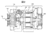
また、図2は、本実施例における圧縮機本体とモータが一体となったスクロール式圧縮機本体1の横断面図である。図2において、モータ20は、アキシャルギャップ型回転モータであって、1ステータ2ロータ型を示している。ステータ21は、モータケーシング24のシャフト23の軸方向中央部に配置、固定され、2つのロータ22が、シャフト23の軸方向にステータ21と対向しステータ21を挟む形で配置される。軸方向にロータとステータを対向させた構造であるため、ラジアルギャップ型に比べて軸方向長さを短くでき、モータ自体を薄型化できる特徴がある。なお、25は冷却ファンである。
Further, FIG. 2 is a cross-sectional view of the scroll type compressor main body 1 in which the compressor main body and the motor are integrated in this embodiment. In FIG. 2, the
また、圧縮機本体10は、主として、旋回スクロール11と固定スクロール12を備え、旋回スクロール11は、シャフト23によって旋回運動を行い、渦巻状のラップ部が立設された固定スクロール12と対面する位置で該固定スクロールのラップ部との間に複数の圧縮室を画成する渦巻状のラップ部が立設されており、固定スクロール12との間に構成される圧縮室を中心に向かうに従い縮小させることで圧縮を行う。13が圧縮空気の吐出口である。
Further, the compressor
なお、アキシャルギャップ型回転モータは、ロータ22として、ロータヨークに円環状に永久磁石が配置されており、いわゆるPM(Permanent Magnet)モータである。よって、図2に示した、本実施例でのスクロール式圧縮機本体1は、PMモータ直動のスクロール式圧縮機本体である。PMモータにおいては、磁場と磁極の極性を合わせる必要があり、インバータによる回転制御が一般的であり、インバータが認識している回転数と実際のモータの回転数とが一致しない脱調と呼ばれる現象を防ぐ必要がある。
The axial gap type rotary motor is a so-called PM (Permanent Magnet) motor in which permanent magnets are arranged in an annular shape on the rotor yoke as the
次に、図1において、その動作について説明する。従来、圧縮機の運転を停止すると、空気タンク内の圧縮空気が圧縮機本体の圧縮室内に逆流して回転部分が逆回転する不具合を解決するために逆止弁を設けているが、逆止弁が故障して圧縮空気の逆流を遮断できなくなった場合には、圧縮運転を停止したときに、旋回スクロールが運転時とは逆方向に高速回転してしまい、遠心力による破損等の圧縮機本体の寿命を早めるという問題が生じる。また、PMモータが逆回転することで起電力が発生し、インバータ2のコンデンサが破裂するなどの問題も生じる。そこで、本実施例では、圧縮空気の逆流を完全には遮断せず流量を制限する逆流制御弁8を、逆止弁6と直列に接続する。これにより、逆止弁6が故障して圧縮空気の逆流を遮断できなくなっても、逆流制御弁8で逆流の流量が制限されているので、圧縮機本体の圧縮室内に逆流する量は少量となり、旋回スクロール11の逆方向回転は低速となる。このため、遠心力による破損の問題や起電力によるインバータ2のコンデンサ破裂の問題などを解消できる。また、インバータ2で圧縮機本体の旋回スクロールの逆回転を検知することで、逆止弁6が故障していることを判断できる。具体的には、モータの電圧、電流を観測することで検知できる。
Next, in FIG. 1, the operation will be described. Conventionally, when the operation of the compressor is stopped, a check valve is provided to solve the problem that the compressed air in the air tank flows back into the compression chamber of the compressor body and the rotating part rotates in the reverse direction. If the valve breaks down and the backflow of compressed air cannot be blocked, when the compression operation is stopped, the swivel scroll will rotate at high speed in the opposite direction to the operation, and the compressor will be damaged by centrifugal force. The problem of shortening the life of the main body arises. Further, the PM motor rotates in the reverse direction to generate an electromotive force, which causes a problem that the capacitor of the
このように、圧縮運転を停止したときに、完全に圧縮空気の逆流を遮断せず、少量を逆流させることで、圧縮機本体の寿命低減を防止するとともに、逆止弁が故障したかを判断できる。逆流制御弁8の流量制限は、例えば、全量の1/7に制限すれば良い。
In this way, when the compression operation is stopped, the backflow of compressed air is not completely blocked, and a small amount of backflow is allowed to prevent the life of the compressor body from being shortened and determine whether the check valve has failed. it can. The flow rate limit of the
また、圧縮運転を停止したときに、完全に圧縮空気の逆流を遮断しないために、吐出配管内に残存した圧縮空気が圧縮機本体の圧縮室内に逆流してもよい。そのため、圧縮機本体の吐出口近傍に逆止弁を設ける必要がなく、吐出口からの高温の圧縮空気による逆止弁の劣化も避けることが出来る。すなわち、逆止弁6を第1のアフタクーラ5の後に配置することで、熱による逆止弁の劣化を避けることができる。
Further, when the compression operation is stopped, the compressed air remaining in the discharge pipe may flow back into the compression chamber of the compressor main body so as not to completely block the backflow of the compressed air. Therefore, it is not necessary to provide a check valve in the vicinity of the discharge port of the compressor body, and deterioration of the check valve due to high-temperature compressed air from the discharge port can be avoided. That is, by arranging the check valve 6 after the
次に、逆流制御弁の具体例について説明する。図3は、本実施例におけるボール式逆流制御弁の構成図である。図3(A)は横断面図を示しており、ボール式逆流制御弁80は、ボディ81とキャップ82とボール83とストッパ84から構成される。また、図3(B)はストッパ84の正面図を示している。図3(B)に示すように、ストッパ84には孔85が設けられている。
Next, a specific example of the check valve will be described. FIG. 3 is a configuration diagram of a ball-type check valve in this embodiment. FIG. 3A shows a cross-sectional view, and the ball-
図3(A)において、ボール式逆流制御弁80は、ボール83がボディ81内を移動可能に設けられており、圧縮空気が流入ポート80A内に流入したときには、ボール83がストッパ84で移動を制限され、ストッパ84に設けられた孔85から圧縮空気が流出ポート80B側へと流通するのを許す構成となっている。また、圧縮空気が流出ポート80Bから流入する場合は、ボール83がボディ81のテーパ面81Aによって移動を制限される。ここで、テーパ面81Aの表面粗さを粗くすることで、ボール83とテーパ面81Aとの隙間から圧縮空気が流入ポート80A側へ漏れることになる。これにより、逆流する流量を制限することが出来る。なお、テーパ面81Aの表面粗さを利用するのではなく、テーパ面81Aに溝を設けることで制限した圧縮空気を流通するようにしても良い。
In FIG. 3A, the ball
また、逆流制御弁の別の具体例について説明する。図4は、本実施例におけるディスク弁式逆流制御弁の構成図である。図4(A)は縦断面図を示しており、ディスク弁式逆流制御弁90は、流入ポート90Aおよび流出ポート90Bが設けられた弁ケース91と、弁ケース91の一部を構成し弁座92Aおよび開口部92Bが設けられた隔壁92と、弁ケース91のねじ穴に螺着され、軸方向にガイド穴93が形成されたねじ94と、段付の円柱体として一体形成され一部がねじ94のガイド穴93に摺動可能に挿嵌されたディスク弁95とから構成されている。
Further, another specific example of the check valve will be described. FIG. 4 is a configuration diagram of a disc valve type check valve in this embodiment. FIG. 4A shows a vertical sectional view. The disc valve
また、図4(B)は、図4(A)におけるa−aから見た弁座92Aの正面図である。なお図4(B)におけるb−bから見た断面図が図4(A)である。図4(B)に示すように、弁座92Aは、溝92Cを有している。
Further, FIG. 4B is a front view of the
図4(A)において、ディスク弁式逆流制御弁90は、圧縮空気が流入ポート90A内に流入したときには、ディスク弁95が弁座92Aから離間することで、弁座92Aとディスク弁95との間から圧縮空気が流出ポート90B側へと流通するのを許す構成となっている。また、圧縮空気が流出ポート90Bから流入する場合は、ディスク弁95が弁座92Aと密着するが、弁座92Aには溝92Cが設けられているので、ディスク弁95と溝92Cの隙間から圧縮空気が流入ポート90A側へ漏れることになる。これにより、逆流する流量を制限することが出来る。また、図4(C)のように、弁座92Aに溝を設けず、ディスク弁95に孔95Cを設けることで、その穴から圧縮空気を流入ポート90A側へ逃がすことにより同様の効果を得ることができる。
In FIG. 4A, in the disc valve type
以上のように、本実施例は、回転式容積型圧縮機であって、回転によって容積を減じて媒体の圧縮を行う圧縮機本体と、圧縮機本体の吐出口から排出した圧縮媒体を流通させる吐出配管と、圧縮機本体への圧縮媒体の逆流を遮断する逆止弁と、圧縮媒体の所定量の逆流が可能な逆流制御弁とを有し、逆止弁と逆流制御弁を吐出配管を介して直列に配置した構成とした。 As described above, the present embodiment is a rotary positive displacement compressor, in which a compressor main body that reduces the volume by rotation to compress the medium and a compression medium discharged from the discharge port of the compressor main body are circulated. It has a discharge pipe, a check valve that shuts off the backflow of the compression medium to the compressor body, and a check valve that allows a predetermined amount of backflow of the compression medium. The check valve and the check valve are used for the discharge pipe. It was configured to be arranged in series via.
これにより、圧縮空気の逆流を完全には遮断せず流量を制限する逆流制御弁を逆止弁と直列に接続することにより、圧縮運転を停止したときに、逆止弁が故障しても、圧縮機本体に逆流する量は少量となり、圧縮機本体の寿命低減を防止するとともに、逆止弁が故障したかを判断できる。 As a result, by connecting a check valve that limits the flow rate without completely shutting off the backflow of compressed air in series with the check valve, even if the check valve fails when the compression operation is stopped, The amount of backflow to the compressor body is small, which prevents the life of the compressor body from being shortened and makes it possible to determine whether the check valve has failed.
以上実施例について説明したが、本発明は上記した実施例に限定されるものではなく、様々な変形例が含まれる。例えば、上記した実施例はスクロール式圧縮機を用いて空気を圧縮するスクロール圧縮機を例にとって説明したが、これに限定されるものではなく、例えば、スクリュー式圧縮機でも良い。 Although the examples have been described above, the present invention is not limited to the above-mentioned examples, and various modifications are included. For example, the above-described embodiment has been described by taking a scroll compressor that compresses air using a scroll compressor as an example, but the present invention is not limited to this, and for example, a screw compressor may be used.
1:スクロール式圧縮機本体、2:インバータ、3:電源、4:吐出配管、5:第1のアフタクーラ、6:逆止弁、7:第2のアフタクーラ、8:逆流制御弁、9:エアードライヤ、10:圧縮機本体、11:旋回スクロール、12:固定スクロール、13:吐出口、20:モータ、21:ステータ、22:ロータ、23:シャフト、24:モータケーシング、25:冷却ファン、80:ボール式逆流制御弁、80A:流入ポート、80B:流出ポート、81:ボディ、81A:テーパ面、82:キャップ、83:ボール、84:ストッパ、85:孔、90:ディスク弁式逆流制御弁、90A:流入ポート、90B:流出ポート、91:弁ケース、92:隔壁、92A:弁座、92B:開口部、92C:溝、93:ガイド穴、94:ねじ、95:ディスク弁、95C:孔 1: Scroll compressor body 2: Inverter 3: Power supply 4: Discharge piping 5: First aftercooler, 6: Check valve, 7: Second aftercooler, 8: Check valve, 9: Air Dryer, 10: Compressor body, 11: Swing scroll, 12: Fixed scroll, 13: Discharge port, 20: Motor, 21: Stator, 22: Rotor, 23: Shaft, 24: Motor casing, 25: Cooling fan, 80 : Ball type check valve, 80A: Inflow port, 80B: Outflow port, 81: Body, 81A: Tapered surface, 82: Cap, 83: Ball, 84: Stopper, 85: Hole, 90: Disc valve type check valve , 90A: Inflow port, 90B: Outflow port, 91: Valve case, 92: Partition, 92A: Valve seat, 92B: Opening, 92C: Groove, 93: Guide hole, 94: Screw, 95: Disc valve, 95C: Hole
Claims (6)
前記逆止弁と前記逆流制御弁を前記吐出配管を介して直列に配置し、
前記逆流制御弁は、ボール式逆流制御弁またはディスク弁式逆流制御弁であることを特徴とする回転式容積型圧縮機。 A compressor body that reduces the volume by rotation to compress the medium, a discharge pipe that distributes the compression medium discharged from the discharge port of the compressor body, and a reverse flow that blocks the backflow of the compression medium to the compressor body. It has a stop valve and a check valve that allows a predetermined amount of backflow of the compression medium and allows forward flow of the compression medium from the compressor body.
The check valve and the check valve are arranged in series via the discharge pipe .
The check valve is a rotary positive displacement compressor characterized by being a ball type backflow control valve or a disc valve type backflow control valve .
前記圧縮機本体は、旋回スクロールと固定スクロールとを備えたスクロール式の圧縮機本体であることを特徴とする回転式容積型圧縮機。 The rotary positive displacement compressor according to claim 1.
The compressor body is a rotary positive displacement compressor characterized by being a scroll type compressor body having a swivel scroll and a fixed scroll.
前記圧縮機本体を駆動するPMモータと、該PMモータをインバータ制御する制御部を有することを特徴とする回転式容積型圧縮機。 The rotary positive displacement compressor according to claim 2.
A rotary positive displacement compressor having a PM motor for driving the compressor main body and a control unit for controlling the PM motor with an inverter.
前記制御部は、前記旋回スクロールの回転を検知する逆回転検知部を備えることを特徴とする回転式容積型圧縮機。 The rotary positive displacement compressor according to claim 3.
The control unit is a rotary positive displacement compressor including a reverse rotation detection unit that detects the rotation of the swivel scroll.
前記PMモータは、シャフトの軸方向にロータとステータを対向させた構造のアキシャルギャップ型回転モータであることを特徴とする回転式容積型圧縮機。 The rotary positive displacement compressor according to claim 3.
The PM motor is a rotary positive displacement compressor characterized by being an axial gap type rotary motor having a structure in which a rotor and a stator face each other in the axial direction of a shaft.
前記圧縮機本体の吐出口と前記逆止弁との間に前記吐出口から排出した圧縮媒体を冷却するアフタクーラを配置したことを特徴とする回転式容積型圧縮機。 The rotary positive displacement compressor according to claim 1.
A rotary positive displacement compressor characterized in that an aftercooler for cooling the compression medium discharged from the discharge port is arranged between the discharge port of the compressor main body and the check valve.
Applications Claiming Priority (1)
| Application Number | Priority Date | Filing Date | Title |
|---|---|---|---|
| PCT/JP2017/003472 WO2018142486A1 (en) | 2017-01-31 | 2017-01-31 | Rotary displacement compressor |
Publications (2)
| Publication Number | Publication Date |
|---|---|
| JPWO2018142486A1 JPWO2018142486A1 (en) | 2019-06-27 |
| JP6763976B2 true JP6763976B2 (en) | 2020-09-30 |
Family
ID=63040324
Family Applications (1)
| Application Number | Title | Priority Date | Filing Date |
|---|---|---|---|
| JP2018565125A Active JP6763976B2 (en) | 2017-01-31 | 2017-01-31 | Revolver positive displacement compressor |
Country Status (5)
| Country | Link |
|---|---|
| US (1) | US11401934B2 (en) |
| EP (1) | EP3578821B1 (en) |
| JP (1) | JP6763976B2 (en) |
| CN (1) | CN110139989B (en) |
| WO (1) | WO2018142486A1 (en) |
Families Citing this family (1)
| Publication number | Priority date | Publication date | Assignee | Title |
|---|---|---|---|---|
| CN109269039B (en) * | 2018-08-06 | 2020-11-10 | 珠海格力电器股份有限公司 | Control method of compressor and refrigerant circulating system |
Family Cites Families (24)
| Publication number | Priority date | Publication date | Assignee | Title |
|---|---|---|---|---|
| US2682281A (en) * | 1950-02-27 | 1954-06-29 | Pacific Pumps Inc | Ball valve cage with resilient ball guide |
| JPS4942891Y1 (en) * | 1970-08-27 | 1974-11-25 | ||
| DE3517694A1 (en) * | 1984-05-21 | 1985-11-21 | Mitsubishi Electric Corp | CONTROL CIRCUIT FOR AN INVERTER |
| JPH04101093A (en) * | 1990-08-20 | 1992-04-02 | Tokico Ltd | Scroll type compressor |
| JP2966575B2 (en) * | 1991-05-29 | 1999-10-25 | 株式会社日立製作所 | Oil-free scroll compressor |
| JP3353979B2 (en) | 1993-11-18 | 2002-12-09 | トキコ株式会社 | Scroll air compressor |
| EP0863313A1 (en) | 1997-03-04 | 1998-09-09 | Anest Iwata Corporation | Two stage scroll compressor |
| JPH11182480A (en) | 1997-12-16 | 1999-07-06 | Tokico Ltd | Rotary compressor |
| JPH11303778A (en) * | 1998-04-24 | 1999-11-02 | Hitachi Ltd | Oil-free scroll compressor |
| US7442239B2 (en) * | 2003-03-24 | 2008-10-28 | Ingersoll-Rand Energy Systems Corporation | Fuel-conditioning skid |
| JP2004332556A (en) * | 2003-04-30 | 2004-11-25 | Tokico Ltd | Multistage compressor |
| JP4561225B2 (en) * | 2004-08-05 | 2010-10-13 | ダイキン工業株式会社 | Positive displacement expander and fluid machinery |
| US7237569B2 (en) * | 2005-03-09 | 2007-07-03 | Globe Union Industrial Corp. | Ball check valve |
| KR20090113241A (en) * | 2006-06-28 | 2009-10-29 | 가부시키가이샤 야스카와덴키 | Inverter control device and its operation method |
| US20080178948A1 (en) | 2007-01-26 | 2008-07-31 | Max Wilmshurst | Safety Leaky Check Valve for Slow Bleed of Compressed Air |
| JP5291317B2 (en) * | 2007-09-28 | 2013-09-18 | 日立オートモティブシステムズ株式会社 | Scroll type fluid machine and air suspension device using the same |
| JP5039587B2 (en) * | 2008-01-31 | 2012-10-03 | 株式会社日立産機システム | Scroll compressor |
| CN101707464A (en) * | 2009-12-04 | 2010-05-12 | 北京工业大学 | Anti-reversion starting device of line-start permanent magnet synchronous motor and control method thereof |
| US8988028B2 (en) * | 2011-08-17 | 2015-03-24 | Trane International Inc. | Reverse rotation braking for a PM motor |
| FR2985113B1 (en) * | 2011-12-21 | 2014-01-24 | Michelin Soc Tech | PILOT INVERTER WITH ABNORMAL TORQUE DETECTION DETECTOR |
| JP6001356B2 (en) * | 2012-06-29 | 2016-10-05 | 株式会社ヴァレオジャパン | Electric compressor |
| BE1021301B1 (en) * | 2013-09-05 | 2015-10-26 | Atlas Copco Airpower, Naamloze Vennootschap | COMPRESSOR DEVICE |
| JP6513345B2 (en) * | 2014-07-03 | 2019-05-15 | ナブテスコ株式会社 | Air compressor |
| CN104235441B (en) * | 2014-09-03 | 2016-08-24 | 黄健山 | backflow prevention valve |
-
2017
- 2017-01-31 JP JP2018565125A patent/JP6763976B2/en active Active
- 2017-01-31 CN CN201780082044.5A patent/CN110139989B/en active Active
- 2017-01-31 EP EP17895137.2A patent/EP3578821B1/en active Active
- 2017-01-31 WO PCT/JP2017/003472 patent/WO2018142486A1/en unknown
- 2017-01-31 US US16/475,572 patent/US11401934B2/en active Active
Also Published As
| Publication number | Publication date |
|---|---|
| CN110139989B (en) | 2021-02-09 |
| CN110139989A (en) | 2019-08-16 |
| EP3578821B1 (en) | 2023-08-16 |
| EP3578821A1 (en) | 2019-12-11 |
| EP3578821A4 (en) | 2020-09-02 |
| WO2018142486A1 (en) | 2018-08-09 |
| JPWO2018142486A1 (en) | 2019-06-27 |
| US11401934B2 (en) | 2022-08-02 |
| US20190338773A1 (en) | 2019-11-07 |
Similar Documents
| Publication | Publication Date | Title |
|---|---|---|
| JP4516123B2 (en) | Variable displacement rotary compressor and method of operating the same | |
| JP5383632B2 (en) | Screw compressor | |
| JPH08312582A (en) | Reversal preventing device for compressor | |
| JP4516120B2 (en) | Variable displacement rotary compressor and method of operating the same | |
| JP5447149B2 (en) | Vane pump | |
| JP4947205B2 (en) | Screw compressor | |
| KR100451651B1 (en) | The structure for preventing the reverse - rotation of centrifugal compressor | |
| KR20190130936A (en) | Turbo Compressor Having a cooling channel | |
| KR20130074392A (en) | Scroll compressor | |
| JP6763976B2 (en) | Revolver positive displacement compressor | |
| JP6113259B2 (en) | Screw compressor | |
| JP4516122B2 (en) | Volume variable type rotary compressor, method of operating the same, and method of operating an air conditioner including the same | |
| KR20180118455A (en) | Turbo compressor | |
| JP2020133577A (en) | Compressor | |
| CN110121597B (en) | Scroll compressor having a plurality of scroll members | |
| JP4024605B2 (en) | Scroll compressor with valve structure | |
| WO2022249239A1 (en) | Compressor and refrigeration cycle device | |
| KR100868267B1 (en) | Turbo blower | |
| JPH06108982A (en) | Fail-safe mechanical oil interrupter for screw compressor | |
| KR100611323B1 (en) | Tandem compressor for air conditioner and its control method | |
| JP2009041401A (en) | Electrically-operated compressor | |
| JP2014231782A (en) | Gas compressor and method for controlling gas compressor | |
| JPS58170887A (en) | Vane compressor |
Legal Events
| Date | Code | Title | Description |
|---|---|---|---|
| A621 | Written request for application examination |
Free format text: JAPANESE INTERMEDIATE CODE: A621 Effective date: 20190222 |
|
| A131 | Notification of reasons for refusal |
Free format text: JAPANESE INTERMEDIATE CODE: A131 Effective date: 20200128 |
|
| A521 | Request for written amendment filed |
Free format text: JAPANESE INTERMEDIATE CODE: A523 Effective date: 20200327 |
|
| A131 | Notification of reasons for refusal |
Free format text: JAPANESE INTERMEDIATE CODE: A131 Effective date: 20200428 |
|
| A601 | Written request for extension of time |
Free format text: JAPANESE INTERMEDIATE CODE: A601 Effective date: 20200625 |
|
| A521 | Request for written amendment filed |
Free format text: JAPANESE INTERMEDIATE CODE: A523 Effective date: 20200813 |
|
| TRDD | Decision of grant or rejection written | ||
| A01 | Written decision to grant a patent or to grant a registration (utility model) |
Free format text: JAPANESE INTERMEDIATE CODE: A01 Effective date: 20200818 |
|
| A61 | First payment of annual fees (during grant procedure) |
Free format text: JAPANESE INTERMEDIATE CODE: A61 Effective date: 20200910 |
|
| R150 | Certificate of patent or registration of utility model |
Ref document number: 6763976 Country of ref document: JP Free format text: JAPANESE INTERMEDIATE CODE: R150 |