JP6762085B2 - Conveyor belt - Google Patents
Conveyor belt Download PDFInfo
- Publication number
- JP6762085B2 JP6762085B2 JP2015152058A JP2015152058A JP6762085B2 JP 6762085 B2 JP6762085 B2 JP 6762085B2 JP 2015152058 A JP2015152058 A JP 2015152058A JP 2015152058 A JP2015152058 A JP 2015152058A JP 6762085 B2 JP6762085 B2 JP 6762085B2
- Authority
- JP
- Japan
- Prior art keywords
- belt
- body layer
- core body
- conveyor belt
- strength
- Prior art date
- Legal status (The legal status is an assumption and is not a legal conclusion. Google has not performed a legal analysis and makes no representation as to the accuracy of the status listed.)
- Active
Links
- 229920001971 elastomer Polymers 0.000 claims description 51
- 239000005060 rubber Substances 0.000 claims description 51
- 230000002093 peripheral effect Effects 0.000 claims description 13
- 239000010410 layer Substances 0.000 description 92
- 239000000835 fiber Substances 0.000 description 8
- 239000012792 core layer Substances 0.000 description 4
- 230000003014 reinforcing effect Effects 0.000 description 3
- 229920002978 Vinylon Polymers 0.000 description 2
- 229920006231 aramid fiber Polymers 0.000 description 2
- 229920001778 nylon Polymers 0.000 description 2
- 229920000728 polyester Polymers 0.000 description 2
- 238000004073 vulcanization Methods 0.000 description 2
- 244000043261 Hevea brasiliensis Species 0.000 description 1
- 239000006229 carbon black Substances 0.000 description 1
- 150000001993 dienes Chemical class 0.000 description 1
- 239000000463 material Substances 0.000 description 1
- 229920003052 natural elastomer Polymers 0.000 description 1
- 229920001194 natural rubber Polymers 0.000 description 1
- 239000002356 single layer Substances 0.000 description 1
Images


Classifications
-
- B—PERFORMING OPERATIONS; TRANSPORTING
- B65—CONVEYING; PACKING; STORING; HANDLING THIN OR FILAMENTARY MATERIAL
- B65G—TRANSPORT OR STORAGE DEVICES, e.g. CONVEYORS FOR LOADING OR TIPPING, SHOP CONVEYOR SYSTEMS OR PNEUMATIC TUBE CONVEYORS
- B65G15/00—Conveyors having endless load-conveying surfaces, i.e. belts and like continuous members, to which tractive effort is transmitted by means other than endless driving elements of similar configuration
- B65G15/30—Belts or like endless load-carriers
- B65G15/32—Belts or like endless load-carriers made of rubber or plastics
- B65G15/34—Belts or like endless load-carriers made of rubber or plastics with reinforcing layers, e.g. of fabric
-
- B—PERFORMING OPERATIONS; TRANSPORTING
- B32—LAYERED PRODUCTS
- B32B—LAYERED PRODUCTS, i.e. PRODUCTS BUILT-UP OF STRATA OF FLAT OR NON-FLAT, e.g. CELLULAR OR HONEYCOMB, FORM
- B32B5/00—Layered products characterised by the non- homogeneity or physical structure, i.e. comprising a fibrous, filamentary, particulate or foam layer; Layered products characterised by having a layer differing constitutionally or physically in different parts
- B32B5/02—Layered products characterised by the non- homogeneity or physical structure, i.e. comprising a fibrous, filamentary, particulate or foam layer; Layered products characterised by having a layer differing constitutionally or physically in different parts characterised by structural features of a fibrous or filamentary layer
- B32B5/024—Woven fabric
-
- B—PERFORMING OPERATIONS; TRANSPORTING
- B32—LAYERED PRODUCTS
- B32B—LAYERED PRODUCTS, i.e. PRODUCTS BUILT-UP OF STRATA OF FLAT OR NON-FLAT, e.g. CELLULAR OR HONEYCOMB, FORM
- B32B2307/00—Properties of the layers or laminate
- B32B2307/50—Properties of the layers or laminate having particular mechanical properties
- B32B2307/554—Wear resistance
-
- B—PERFORMING OPERATIONS; TRANSPORTING
- B32—LAYERED PRODUCTS
- B32B—LAYERED PRODUCTS, i.e. PRODUCTS BUILT-UP OF STRATA OF FLAT OR NON-FLAT, e.g. CELLULAR OR HONEYCOMB, FORM
- B32B2433/00—Closed loop articles
- B32B2433/02—Conveyor belts
-
- B—PERFORMING OPERATIONS; TRANSPORTING
- B65—CONVEYING; PACKING; STORING; HANDLING THIN OR FILAMENTARY MATERIAL
- B65G—TRANSPORT OR STORAGE DEVICES, e.g. CONVEYORS FOR LOADING OR TIPPING, SHOP CONVEYOR SYSTEMS OR PNEUMATIC TUBE CONVEYORS
- B65G2207/00—Indexing codes relating to constructional details, configuration and additional features of a handling device, e.g. Conveyors
- B65G2207/48—Wear protection or indication features
-
- B—PERFORMING OPERATIONS; TRANSPORTING
- B65—CONVEYING; PACKING; STORING; HANDLING THIN OR FILAMENTARY MATERIAL
- B65G—TRANSPORT OR STORAGE DEVICES, e.g. CONVEYORS FOR LOADING OR TIPPING, SHOP CONVEYOR SYSTEMS OR PNEUMATIC TUBE CONVEYORS
- B65G2812/00—Indexing codes relating to the kind or type of conveyors
- B65G2812/02—Belt or chain conveyors
- B65G2812/02128—Belt conveyors
- B65G2812/02178—Belt conveyors characterised by the material
- B65G2812/02198—Non-metallic belts
-
- B—PERFORMING OPERATIONS; TRANSPORTING
- B65—CONVEYING; PACKING; STORING; HANDLING THIN OR FILAMENTARY MATERIAL
- B65G—TRANSPORT OR STORAGE DEVICES, e.g. CONVEYORS FOR LOADING OR TIPPING, SHOP CONVEYOR SYSTEMS OR PNEUMATIC TUBE CONVEYORS
- B65G2812/00—Indexing codes relating to the kind or type of conveyors
- B65G2812/02—Belt or chain conveyors
- B65G2812/02128—Belt conveyors
- B65G2812/02217—Belt conveyors characterised by the configuration
Landscapes
- Engineering & Computer Science (AREA)
- Mechanical Engineering (AREA)
- Textile Engineering (AREA)
- Belt Conveyors (AREA)
Description
本発明は、コンベヤベルトに関し、さらに詳しくは、上カバーゴムに投入される搬送物によって生じるコンベヤベルトの縦裂きの発生を抑制してコンベヤベルトの耐用期間を長くすることができるコンベヤベルトに関するものである。 The present invention relates to a conveyor belt, and more particularly to a conveyor belt capable of suppressing the occurrence of vertical tears of the conveyor belt caused by an object charged into the upper cover rubber and extending the service life of the conveyor belt. is there.
コンベヤベルトの上カバーゴムと下カバーゴムとの間には、コンベヤベルト張設時の張力を負担する心体層が埋設されている。心体層が損傷するとコンベヤベルトを正常に張設することが困難になるため、コンベヤベルトの稼働を確保するには、心体層の損傷を防止することが重要である。 A core body layer that bears the tension when the conveyor belt is stretched is embedded between the upper cover rubber and the lower cover rubber of the conveyor belt. When the heart body layer is damaged, it becomes difficult to stretch the conveyor belt normally. Therefore, it is important to prevent the heart body layer from being damaged in order to ensure the operation of the conveyor belt.
心体層として用いられる帆布は、例えば縦糸と横糸を平織りすることにより構成されている。そして、ベルト長手方向に延在する縦糸とベルト幅方向に延在する横糸とは仕様が異なっていることが一般的である(例えば、特許文献1の段落0023等参照)。即ち、心体層は、コンベヤベルトに作用する張力を負担することを主眼にして設計されているため、ベルト長手方向の強力は相応に高く設定されているが、ベルト幅方向の強力は帆布(縦糸)の乱れを防止できる程度の非常に低い強力に設定されている。例えば、心体層のベルト幅方向の強力はベルト長手方向の強力の15%程度である。 The canvas used as the heart layer is composed of, for example, plain weave of warp and weft. The specifications of the warp threads extending in the longitudinal direction of the belt and the weft threads extending in the width direction of the belt are generally different (see, for example, paragraph 0023 of Patent Document 1). That is, since the mind body layer is designed mainly to bear the tension acting on the conveyor belt, the strength in the longitudinal direction of the belt is set to be correspondingly high, but the strength in the width direction of the belt is canvas ( It is set to a very low strength that can prevent the warp threads from being disturbed. For example, the strength of the mind body layer in the belt width direction is about 15% of the strength in the belt longitudinal direction.
そのため、上カバーゴムに搬送物が投入された際に、その投入高さが大きい、或いは、搬送物の重量が大きい場合には、その搬送物による衝撃によって心体層の横糸が破断し、これに伴いコンベヤベルト(心体層)にはベルト長手方向の亀裂(縦裂き)が生じることがある。この縦裂きは心体層の致命的な損傷につながるため、コンベヤベルトの耐用期間も短くなるという問題がある。特に、搬送物の投入高さが大きい場合、或いは、搬送物の重量が大きい場合は、横糸が早期に破損する可能性が高くなるため、コンベヤベルトの耐用期間を長くするには一段と不利になる。 Therefore, when the conveyed object is charged into the upper cover rubber, if the input height is large or the weight of the conveyed object is large, the weft of the heart body layer is broken by the impact of the conveyed object. As a result, cracks (longitudinal tears) in the longitudinal direction of the belt may occur in the conveyor belt (heart layer). Since this vertical tear leads to fatal damage to the body layer, there is a problem that the service life of the conveyor belt is shortened. In particular, when the input height of the transported object is large, or when the weight of the transported object is large, the weft is more likely to be damaged at an early stage, which is further disadvantageous for extending the service life of the conveyor belt. ..
本発明の目的は、上カバーゴムに投入される搬送物によって生じるコンベヤベルトの縦裂きの発生を抑制してコンベヤベルトの耐用期間を長くすることができるコンベヤベルトを提供することにある。 An object of the present invention is to provide a conveyor belt capable of suppressing the occurrence of vertical tears of the conveyor belt caused by a conveyed object put into the upper cover rubber and extending the service life of the conveyor belt.
上記目的を達成するため本発明のコンベヤベルトは、平織構造の帆布で構成された少なくとも1層の心体層と、この心体層を挟んで上下にそれぞれ位置する上カバーゴムおよび下カバーゴムとを備えて、前記下カバーゴム側が下方に突出してトラフ状に保持された状態で前記上カバーゴムに載置されている搬送物が搬送されるコンベヤベルトにおいて、すべての前記心体層のベルト幅方向強力がベルト長手方向強力の30%以上70%以下であることを特徴とする。
また、本発明の別のコンベヤベルトは、平織構造の帆布で構成された少なくとも1層の心体層と、この心体層を挟んで上下にそれぞれ位置する上カバーゴムおよび下カバーゴムとを備えて、前記下カバーゴム側が下方に突出してトラフ状に保持された状態で前記上カバーゴムに載置されている搬送物が搬送されるコンベヤベルトにおいて、前記心体層のうち、少なくとも1層の心体層のベルト幅方向強力がベルト長手方向強力の30%以上70%以下であり、ベルト幅方向強力がベルト長手方向強力の30%以上70%以下である前記心体層が、ベルト幅方向で中央部のみに位置していることを特徴とする。
In order to achieve the above object, the conveyor belt of the present invention includes at least one core body layer made of plain weave canvas, and upper cover rubber and lower cover rubber located above and below the core body layer. In a conveyor belt in which the conveyed object placed on the upper cover rubber is conveyed in a state where the lower cover rubber side protrudes downward and is held in a trough shape, the belt width of all the core body layers is provided. The directional strength is 30% or more and 70% or less of the longitudinal strength of the belt.
Further, another conveyor belt of the present invention includes at least one core body layer made of canvas having a plain weave structure, and upper cover rubber and lower cover rubber located above and below the core body layer, respectively. In the conveyor belt in which the conveyed object placed on the upper cover rubber is conveyed in a state where the lower cover rubber side protrudes downward and is held in a trough shape, at least one of the core body layers The strength in the belt width direction of the core body layer is 30% or more and 70% or less of the strength in the longitudinal direction of the belt, and the strength in the width direction of the belt is 30% or more and 70% or less of the strength in the longitudinal direction of the belt. It is characterized by being located only in the central part.
本発明のコンベヤベルトによれば、少なくとも1層の心体層のベルト幅方向強力をベルト長手方向強力の30%以上70%以下に設定して、ベルト幅方向強力を従来に比して大幅に向上させているので、投入される搬送物による衝撃によって心体層に縦裂きが発生することを防止するには有利になっている。これに伴い、心体層を長期に渡って保護することが可能になり、コンベヤベルトの耐用期間を長くすることができる。 According to the conveyor belt of the present invention, the strength in the belt width direction of at least one core body layer is set to 30% or more and 70% or less of the strength in the longitudinal direction of the belt, and the strength in the belt width direction is significantly increased as compared with the conventional case. Since it is improved, it is advantageous to prevent vertical tears from occurring in the mind body layer due to the impact of the loaded object. Along with this, it becomes possible to protect the mind body layer for a long period of time, and the service life of the conveyor belt can be extended.
ここで、前記心体層のうち、少なくとも最外周側および最内周側の心体層のベルト幅方向強力がベルト長手方向強力の30%以上70%以下である仕様にすることもできる。上カバーゴムに搬送物が投入されると、上カバーゴムの表面寄りの心体層ほど鋭利な搬送物によって破断し易い。また、投入される搬送物から受ける衝撃によるひずみは、非鋭利な搬送物では、下カバーゴム寄りの心体層ほど大きくなる。したがって、この仕様によれば、相対的に過酷な条件になる位置に配置される心体層では縦裂きが生じ難くなる。それ故、効率的に心体層を補強しつつ、コンベヤベルトの耐用期間を長くすることができる。 Here, it is also possible to specify that the strength in the belt width direction of at least the outermost peripheral side and the innermost peripheral side of the core body layer is 30% or more and 70% or less of the belt longitudinal direction strength. When the conveyed object is thrown into the upper cover rubber, the core layer closer to the surface of the upper cover rubber is more likely to be broken by the sharper conveyed object. Further, in the case of a non-sharp conveyed object, the strain due to the impact received from the input conveyed object becomes larger as the core body layer closer to the lower cover rubber. Therefore, according to this specification, vertical tears are less likely to occur in the mind-body layer arranged at a position where the conditions are relatively severe. Therefore, the useful life of the conveyor belt can be extended while efficiently reinforcing the core body layer.
すべての前記心体層のベルト幅方向強力がベルト長手方向強力の30%以上70%以下である仕様にすることもできる。この仕様によれば、すべての心体層が損傷し難くなるので、心体層に縦裂きが発生することを一段と防止し易くなる。 It is also possible to specify that the strength in the belt width direction of all the mind body layers is 30% or more and 70% or less of the strength in the longitudinal direction of the belt. According to this specification, all the mind body layers are less likely to be damaged, so that it becomes easier to prevent the occurrence of vertical tears in the mind body layer.
或いは、ベルト幅方向強力がベルト長手方向強力の30%以上70%以下である前記心体層が、ベルト幅方向で中央部のみに位置している仕様にすることもできる。搬送物は、主にベルト幅方向中央部に投入、載置されるので、この仕様によれば、相対的に過酷な条件になるベルト幅方向中央部の心体層では縦裂きが生じ難くなる。それ故、効率的に心体層を補強しつつ、コンベヤベルトの耐用期間を長くすることができる。 Alternatively, the specification may be such that the core body layer having a belt width direction strength of 30% or more and 70% or less of the belt longitudinal direction strength is located only in the central portion in the belt width direction. Since the transported object is mainly loaded and placed in the central portion in the belt width direction, according to this specification, vertical tearing is less likely to occur in the core body layer in the central portion in the belt width direction, which is a relatively harsh condition. .. Therefore, the useful life of the conveyor belt can be extended while efficiently reinforcing the core body layer.
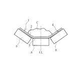
以下、本発明のコンベヤベルトを図に示した実施形態に基づいて説明する。尚、図中の一点鎖線CLはコンベヤベルトのベルト幅方向中心を示している。 Hereinafter, the conveyor belt of the present invention will be described based on the embodiment shown in the figure. The alternate long and short dash line CL in the figure indicates the center of the conveyor belt in the belt width direction.
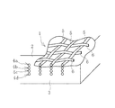
図1〜図3に例示するように本発明のコンベヤベルト1は、心体層4と、心体層4を上下に挟んで配置される上カバーゴム2と下カバーゴム3とを備えていて、これらが加硫工程を経て一体化している。コンベヤベルト1は、その他、ベルト幅方向両端部に配置される耳ゴム等、他の構成要素が適宜追加されて構成される。
As illustrated in FIGS. 1 to 3, the
心体層4は帆布により構成されている。心体層4の構造を詳述すると、縦糸5と横糸6とを平織構造にして構成されていて、その表面がコートゴムにより被覆されている。このコートゴムと上カバーゴム2および下カバーゴム3とが加硫接着により接合され、コートゴムと縦糸5および横糸6とが接合されている。
The
上カバーゴム2、下カバーゴム3としては、例えば、少なくとも天然ゴムを含むジエン系ゴムからなり、カーボンブラックなどによって耐摩耗性を良好にしたゴム組成物が用いられる。上カバーゴム2および下カバーゴム3の層厚は、コンベヤベルト1に要求される性能によって適宜決定される。コートゴムは接着性に優れるゴムである。
As the
心体層4は単層または複層にすることができるが、例えば4層〜8層程度にする。この実施形態では、4層の心体層4a、4b、4c、4dが上下に積層されている。縦糸5には例えば、ポリエステル繊維、ナイロン繊維、アラミド繊維、ビニロン繊維、PBO繊維、高硬度ポリアレート繊維等を用いる。横糸6には例えば、ポリエステル繊維、ナイロン繊維、アラミド繊維、ビニロン繊維、PBO繊維、高硬度ポリアレート繊維等を用いる。縦糸5と横糸6の材質は同じにすることも、異ならせることもできる。
The
縦糸5、横糸6の外径は例えば0.3mm〜1.5mmである。それぞれの心体層4の総厚は例えば1.0mm〜3.0mmである。
The outer diameters of the
コンベヤベルト1は、図4〜図5に例示するように、プーリ7a、7bの間に張設される。コンベヤベルト1はキャリア側では、支持ローラ8によって下方に突出するトラフ状に保持されるので、投入された搬送物Cは主に上カバーゴム2のベルト幅方向中央部に載置される。
The
プーリ7a、7bに張設されたコンベヤベルト1には、ベルト長手方向に所定のセッティングテンションTsが作用している。コンベヤベルト1に作用する張力は実質的に心体層4が負担するので、心体層4のベルト長手方向には常時、所定のセッティングテンションTsが作用することになる。セッティングテンションTsの大きさは、コンベヤベルト1の仕様によって異なり、コンベヤベルト1が正常に稼働する適切な値に設定される。したがって、心体層4のベルト長手方向強力FLは、セッティングテンションTsを十分に負担できる強力に設定されているので、FL≫Tsとなる。
A predetermined setting tension Ts acts on the
本発明では、心体層4のうち、少なくとも1層の心体層4を特別な仕様にしている。特別な仕様の心体層4では、ベルト幅方向強力FWがベルト長手方向強力FLの30%以上70%以下に設定されている。即ち、本発明では、従来に比して心体層4のベルト長手方向強力FLに対するベルト幅方向強力FWの強力の比率(FW/FL)を大幅に向上させている。
In the present invention, at least one of the
具体的には、縦糸5は相対的に高い引張強力(ベルト長手方向強力)を有していて、これに伴って心体層4も相対的に高い引張強力(ベルト長手方向強力FL)を有している。例えば心体層4の単位幅当たりのベルト長手方向強力は芯体層1層(各芯体層4a、4b、4c、4d)当たり250〜500N/mm(心体層4をベルト幅方向(横糸6の延在方向)に50mmの幅で切断して形成した試験片を縦糸5の延在方向に引張った時の破断強力(JIS K6322に準拠して測定))である。横糸6は縦糸5よりは低いが、従来に比して高い引張強力を有していて、これに伴って心体層4も従来に比して高い引張強力(ベルト幅方向強力FW)を有している。例えば心体層4の単位幅当たりのベルト幅方向強力は芯体層1層(各芯体層4a、4b、4c、4d)当たり125〜250N/mm(心体層4をベルト長手方向(縦糸5の延在方向)に50mmの幅で切断して形成した試験片を横糸6の延在方向に引張った時の破断強力(JIS K6322に準拠して測定))である。そして、本発明の心体層4では、ベルト幅方向強力FWがベルト長手方向強力FLの30%以上70%以下に設定されている。
Specifically, the
上カバーゴム2は投入された搬送物Cにより衝撃を受ける。その際に、心体層4は搬送物Cにより押圧されて引張力が作用する。即ち、縦糸5および横糸6には追加的な引張力が作用するので、相対的に横糸6の引張強力が過小であると、横糸6が損傷、破断する。これに伴い、心体層4(コンベヤベルト1)には縦裂きが発生する。
The
そこで本発明では、搬送物Cによるコンベヤベルト1の損傷に関して、従来注目されていなかった心体層4のベルト幅方向強力FWに着目して心体層4に工夫をしている。即ち、ベルト幅方向強力FWがベルト長手方向強力FLの30%以上70%以下に設定されている心体層4を備えているので、この心体層4では横糸6が損傷、破断し難くなっている。そのため、縦裂きの発生を抑えることが可能になっている。したがって、コンベヤベルト1の耐用期間を長くするには有利になっている。
Therefore, in the present invention, regarding the damage of the
心体層4のベルト幅方向強力FWがベルト長手方向強力FLの30%未満では、縦裂きを十分に防止することが困難になる。一方、心体層4のベルト幅方向強力FWがベルト長手方向強力FLの70%超であると、コンベヤベルト1のベルト幅方向の曲げ剛性が過大になり、トラフ性が低下する(トラフ形状にし難くなる)。
If the strong FW in the belt width direction of the
本願発明者らの分析によると、上カバーゴム2に搬送物Cが投入された際、搬送物Cの衝突面が比較的尖っていない場合(非鋭利な場合)には、積層された複数の心体層4a〜4dのうち、最内周側にある心体層4dに最も大きな歪みが発生することが判明した。即ち、最内周側の心体層4dは非鋭利な搬送物Cから受ける衝撃によって最も損傷し易い条件にある。そこで、最内周側にある心体層4dは上述した特別な仕様にすることが好ましい。これにより、投入される搬送物Cの衝撃によって心体層4dの横糸6が損傷することを回避し易くなり、縦裂きの発生を防止するには有利になる。
According to the analysis by the inventors of the present application, when the conveyed object C is put into the
また、上カバーゴム2に搬送物Cが投入された際には、上カバーゴム2の表面寄りの心体層4aほど鋭利な搬送物Cによって破断し易い。即ち、最外周側の心体層4aは鋭利な搬送物Cによって最も破断し易い条件にある。そこで、最外周側にある心体層4aも上述した特別な仕様にすることが好ましい。これにより、投入される搬送物Cの衝撃によって心体層4aの横糸6が損傷することを回避し易くなり、縦裂きの発生を防止するには有利になる。
Further, when the conveyed object C is thrown into the
即ち、少なくとも最外周側の心体層4aおよび最内周側の心体層4dを上述した特別な仕様にすることが好ましい。そして、最外周側の心体層4aおよび最内周側の心体層4dのみを上述した特別な仕様にすると、相対的に過酷な条件になる位置に配置される心体層4a、4dを効率的に補強しつつ、コンベヤベルト1の耐用期間を長くすることができる。
That is, it is preferable that at least the outermost peripheral side
鋭利な搬送物Cを搬送するコンベヤベルト1では、最外周側の心体層4aのみを上述の特別な仕様にすることもできる。鋭利ではない搬送物Cを搬送するコンベヤベルト1では、最内周側の心体層4dのみを上述の特別な仕様にすることもできる。
In the
すべての心体層4a〜4dを上述の特別な仕様にすることもできる。この場合は、すべての心体層4a〜4dの横糸6が損傷、破断し難くなるので、縦裂きが発生することを一段と防止し易くなる。
All mind body layers 4a-4d can also be made to the special specifications described above. In this case, the
搬送物Cは、主に上カバーゴム2のベルト幅方向中央部に投入、載置されるので、上述の特別な仕様の心体層4を、ベルト幅方向中央部のみに配置することもできる。ベルト幅方向中央部とは、ベルト幅Bの50%〜80%程度のベルト幅方向中央部の範囲である。この場合は、相対的に過酷な条件になるベルト幅方向中央部の心体層4を効率的に補強しつつ、コンベヤベルト1の耐用期間を長くすることができる。
Since the conveyed object C is mainly inserted and placed in the central portion of the
心体層4のベルト幅方向強力FWをベルト長手方向強力FLの30%以上70%以下に設定することで、心体層4の長手方向の曲げ剛性が高くなることはない。それ故、本発明では、コンベヤベルト1の稼働に要するエネルギが大きくなることはない。
By setting the strong FW in the belt width direction of the
平織構造の帆布からなる心体層を4層積層して、心体層のベルト幅方向強力FWのベルト長手方向強力FLの比率(FW/FL)のみを表1のように異ならせた2種類のコンベヤベルトの試験サンプル(実施例、従来例)を作製した。第1層が上カバーゴムの最も表面寄りに配置され、第2層、第3層、第4層を順に下方に積層した。それぞれの試験サンプルをベース台に載置して、上カバーゴムに錘を落下させて損傷具合を確認した。その結果を表1に示す。錘の質量は60kg、その下端部(上カバーゴムとの接触部)は半径20mmの球面であり、落下高さは1mに設定した。 Two types of core body layers made of plain weave canvas are laminated, and only the ratio (FW / FL) of the belt width direction strong FW and the belt longitudinal direction strong FL of the heart body layer is different as shown in Table 1. Test samples (examples, conventional examples) of the conveyor belt of the above were prepared. The first layer was arranged closest to the surface of the upper cover rubber, and the second layer, the third layer, and the fourth layer were laminated downward in this order. Each test sample was placed on a base base, and a weight was dropped on the upper cover rubber to check the degree of damage. The results are shown in Table 1. The mass of the weight was 60 kg, the lower end portion (contact portion with the upper cover rubber) was a spherical surface with a radius of 20 mm, and the drop height was set to 1 m.

表1の結果から、実施例は、従来例に比して心体層の破損を防止するには有効であり、コンベヤベルトに縦裂きが発生し難いことが分かる。 From the results in Table 1, it can be seen that the examples are more effective in preventing damage to the body layer than the conventional examples, and vertical tears are less likely to occur in the conveyor belt.
1 コンベヤベルト
2 上カバーゴム
3 下カバーゴム
4、4a、4b、4c、4d 心体層
5 縦糸
6 横糸
7a、7b プーリ
8支持ローラ
1
Claims (3)
すべての前記心体層のベルト幅方向強力がベルト長手方向強力の30%以上70%以下であることを特徴とするコンベヤベルト。 It is provided with at least one core body layer made of plain weave canvas, and upper cover rubber and lower cover rubber located above and below the core body layer, respectively, and the lower cover rubber side projects downward. In a conveyor belt in which a conveyed object placed on the upper cover rubber is conveyed while being held in a trough shape.
A conveyor belt characterized in that the strength in the belt width direction of all the core body layers is 30% or more and 70% or less of the strength in the longitudinal direction of the belt.
前記心体層のうち、少なくとも1層の心体層のベルト幅方向強力がベルト長手方向強力の30%以上70%以下であり、ベルト幅方向強力がベルト長手方向強力の30%以上70%以下である前記心体層が、ベルト幅方向で中央部のみに位置していることを特徴とするコンベヤベルト。 It is provided with at least one core body layer made of plain weave canvas, and upper cover rubber and lower cover rubber located above and below the core body layer, respectively, and the lower cover rubber side projects downward. In a conveyor belt in which a conveyed object placed on the upper cover rubber is conveyed while being held in a trough shape.
Wherein among the tension member layer, at least one layer the belt width direction of the tension member layer strength of Ri 70% der less than 30% of the longitudinal direction of the belt strength, the belt width direction tenacity belt longitudinal direction strength of 30% or more 70% A conveyor belt characterized in that the following core body layer is located only in the central portion in the belt width direction .
Priority Applications (6)
| Application Number | Priority Date | Filing Date | Title |
|---|---|---|---|
| JP2015152058A JP6762085B2 (en) | 2015-07-31 | 2015-07-31 | Conveyor belt |
| AU2016302499A AU2016302499B2 (en) | 2015-07-31 | 2016-06-16 | Conveyor belt |
| US15/741,750 US11001449B2 (en) | 2015-07-31 | 2016-06-16 | Conveyor belt |
| CN201680031647.8A CN107614400B (en) | 2015-07-31 | 2016-06-16 | Conveyor belt |
| EP16832617.1A EP3330202A4 (en) | 2015-07-31 | 2016-06-16 | Conveyor belt |
| PCT/JP2016/067886 WO2017022338A1 (en) | 2015-07-31 | 2016-06-16 | Conveyor belt |
Applications Claiming Priority (1)
| Application Number | Priority Date | Filing Date | Title |
|---|---|---|---|
| JP2015152058A JP6762085B2 (en) | 2015-07-31 | 2015-07-31 | Conveyor belt |
Publications (2)
| Publication Number | Publication Date |
|---|---|
| JP2017030915A JP2017030915A (en) | 2017-02-09 |
| JP6762085B2 true JP6762085B2 (en) | 2020-09-30 |
Family
ID=57942795
Family Applications (1)
| Application Number | Title | Priority Date | Filing Date |
|---|---|---|---|
| JP2015152058A Active JP6762085B2 (en) | 2015-07-31 | 2015-07-31 | Conveyor belt |
Country Status (6)
| Country | Link |
|---|---|
| US (1) | US11001449B2 (en) |
| EP (1) | EP3330202A4 (en) |
| JP (1) | JP6762085B2 (en) |
| CN (1) | CN107614400B (en) |
| AU (1) | AU2016302499B2 (en) |
| WO (1) | WO2017022338A1 (en) |
Families Citing this family (1)
| Publication number | Priority date | Publication date | Assignee | Title |
|---|---|---|---|---|
| CN115504159A (en) * | 2022-10-19 | 2022-12-23 | 吴善聪 | Ultrahigh wear-resistant anti-tearing conveying belt |
Family Cites Families (31)
| Publication number | Priority date | Publication date | Assignee | Title |
|---|---|---|---|---|
| US2511581A (en) * | 1946-06-24 | 1950-06-13 | Gail G Grigsby | Conveyer belt |
| US2505354A (en) * | 1946-08-15 | 1950-04-25 | Us Rubber Co | Mechanical belt |
| GB901707A (en) * | 1958-09-25 | 1962-07-25 | Silvertown Rubber Company Ltd | Improvements in laminated belting |
| FR2323601A1 (en) * | 1973-01-12 | 1977-04-08 | Hartmann Karl | CROSS-RIGIDITY CONVEYOR BELT |
| DE2425465B1 (en) * | 1974-05-27 | 1975-03-27 | Clouth Gummiwerke Ag | Conveyor belt |
| DE2519448B1 (en) * | 1975-04-30 | 1976-08-05 | Scholtz Ag Conrad | FABRIC INLAY FOR TRANSVERSIBLE CONVEYOR BELTS |
| US4407333A (en) * | 1981-06-22 | 1983-10-04 | Uniroyal, Inc. | Belting fabric |
| US4526637A (en) * | 1982-01-29 | 1985-07-02 | The Goodyear Tire & Rubber Company | Method of making conveyor belt |
| NL8202410A (en) | 1982-06-14 | 1984-01-02 | Bekaert Sa Nv | REINFORCEMENT STRUCTURE FOR AN ELASTANE OBJECT. |
| JPS60144211A (en) | 1983-12-29 | 1985-07-30 | Tokai Rubber Ind Ltd | Cylindrical conveyor belt |
| US4518647A (en) * | 1984-06-11 | 1985-05-21 | Morrison Company, Inc. | Agricultural belting material |
| NL8602967A (en) * | 1986-11-21 | 1988-06-16 | Dunlop Enerka Bv | CONVEYOR BELT. |
| JPH04251013A (en) * | 1990-12-28 | 1992-09-07 | Yokohama Rubber Co Ltd:The | Conveyor belt |
| CN2411234Y (en) * | 1999-12-25 | 2000-12-20 | 青岛第六橡胶厂 | Conveyer belt with impact anti-tearing strengthening cover and stretchable transhape performance |
| JP2004149267A (en) | 2002-10-31 | 2004-05-27 | Mitsuboshi Belting Ltd | Conveyer belt and its manufacturing method |
| US7484618B2 (en) * | 2005-08-12 | 2009-02-03 | Foust Jerry D | Conveyor for hot materials |
| US20080078657A1 (en) * | 2006-10-03 | 2008-04-03 | J.H. Fenner & Co. Ltd | Oriented needled felt conveyor belt |
| JP5191642B2 (en) * | 2006-10-05 | 2013-05-08 | バンドー化学株式会社 | Conveyor belts and belt conveyors |
| US20080164127A1 (en) * | 2007-01-10 | 2008-07-10 | J.H. Fenner & Co. Ltd | Needled felt and monofilament fabric conveyor belt |
| JP5181478B2 (en) * | 2007-01-15 | 2013-04-10 | 横浜ゴム株式会社 | Conveyor belt |
| US7759266B2 (en) * | 2007-07-13 | 2010-07-20 | Fenner Dunlop Americas, Inc. | Dual crimped warp fabric for conveyor belt applications |
| JP5061790B2 (en) * | 2007-08-13 | 2012-10-31 | 横浜ゴム株式会社 | Conveyor belt |
| JP5169465B2 (en) * | 2008-05-13 | 2013-03-27 | 横浜ゴム株式会社 | Conveyor belt |
| CA2714955C (en) * | 2009-10-09 | 2013-12-31 | Veyance Technologies, Inc. | Conveyor belt with varying flexibility and method of construction of same |
| CN102905561B (en) | 2010-06-11 | 2015-02-18 | 美国圣戈班性能塑料公司 | Cooking belt |
| JP2012035981A (en) * | 2010-08-09 | 2012-02-23 | Bridgestone Corp | Conveyor belt |
| US20120168285A1 (en) * | 2011-01-05 | 2012-07-05 | Honeywell International Inc. | Lightweight reinforced conveyor belt structure |
| CN104444068A (en) * | 2013-09-17 | 2015-03-25 | 天津市天水工业用带有限公司 | Steel wire rope conveying belt |
| WO2015111486A1 (en) * | 2014-01-22 | 2015-07-30 | ニッタ株式会社 | Flat belt |
| CN203682362U (en) * | 2014-01-23 | 2014-07-02 | 青岛华夏橡胶工业有限公司 | Light high-strength steel wire rope core conveying belt |
| US10815061B1 (en) * | 2019-09-12 | 2020-10-27 | Syncrude Canada Ltd. | Conveyor belt with reinforcing block |
-
2015
- 2015-07-31 JP JP2015152058A patent/JP6762085B2/en active Active
-
2016
- 2016-06-16 AU AU2016302499A patent/AU2016302499B2/en active Active
- 2016-06-16 US US15/741,750 patent/US11001449B2/en active Active
- 2016-06-16 CN CN201680031647.8A patent/CN107614400B/en active Active
- 2016-06-16 WO PCT/JP2016/067886 patent/WO2017022338A1/en active Application Filing
- 2016-06-16 EP EP16832617.1A patent/EP3330202A4/en active Pending
Also Published As
| Publication number | Publication date |
|---|---|
| CN107614400A (en) | 2018-01-19 |
| AU2016302499A1 (en) | 2017-12-21 |
| AU2016302499B2 (en) | 2019-06-06 |
| CN107614400B (en) | 2022-09-13 |
| US20180194559A1 (en) | 2018-07-12 |
| EP3330202A1 (en) | 2018-06-06 |
| US11001449B2 (en) | 2021-05-11 |
| EP3330202A4 (en) | 2019-04-24 |
| WO2017022338A1 (en) | 2017-02-09 |
| JP2017030915A (en) | 2017-02-09 |
Similar Documents
| Publication | Publication Date | Title |
|---|---|---|
| EP0237462B1 (en) | Reinforced composite structure | |
| JP4805322B2 (en) | Heavy duty tire | |
| CN104718089B (en) | Cotton tyre cord | |
| JP6762085B2 (en) | Conveyor belt | |
| US10745207B2 (en) | Conveyor belt and belt conveyor device | |
| EP3222563B1 (en) | Conveyor belt | |
| AU2016291894B2 (en) | Conveyor belt | |
| JP6724489B2 (en) | Fiber reinforcement layers for conveyor belts and conveyor belts | |
| CN211106070U (en) | Industrial belt with strong tensile strength | |
| WO2024062669A1 (en) | Conveyor belt and manufacturing method therefor | |
| JP2507847Y2 (en) | V belt for transmission | |
| JP5181478B2 (en) | Conveyor belt | |
| CN209651147U (en) | A kind of oil resistant conveyer | |
| JP2011256012A (en) | Conveyor belt | |
| JPS59124610A (en) | Conveyor belt | |
| JP2004026476A (en) | Conveyer belt | |
| JP2015209327A (en) | Conveyer belt |
Legal Events
| Date | Code | Title | Description |
|---|---|---|---|
| A621 | Written request for application examination |
Free format text: JAPANESE INTERMEDIATE CODE: A621 Effective date: 20180719 |
|
| A131 | Notification of reasons for refusal |
Free format text: JAPANESE INTERMEDIATE CODE: A131 Effective date: 20190514 |
|
| A521 | Request for written amendment filed |
Free format text: JAPANESE INTERMEDIATE CODE: A523 Effective date: 20190625 |
|
| RD07 | Notification of extinguishment of power of attorney |
Free format text: JAPANESE INTERMEDIATE CODE: A7427 Effective date: 20190731 |
|
| A02 | Decision of refusal |
Free format text: JAPANESE INTERMEDIATE CODE: A02 Effective date: 20191126 |
|
| A521 | Request for written amendment filed |
Free format text: JAPANESE INTERMEDIATE CODE: A523 Effective date: 20200226 |
|
| A911 | Transfer to examiner for re-examination before appeal (zenchi) |
Free format text: JAPANESE INTERMEDIATE CODE: A911 Effective date: 20200305 |
|
| A912 | Re-examination (zenchi) completed and case transferred to appeal board |
Free format text: JAPANESE INTERMEDIATE CODE: A912 Effective date: 20200612 |
|
| A61 | First payment of annual fees (during grant procedure) |
Free format text: JAPANESE INTERMEDIATE CODE: A61 Effective date: 20200908 |
|
| R150 | Certificate of patent or registration of utility model |
Ref document number: 6762085 Country of ref document: JP Free format text: JAPANESE INTERMEDIATE CODE: R150 |
|
| S531 | Written request for registration of change of domicile |
Free format text: JAPANESE INTERMEDIATE CODE: R313531 |
|
| R350 | Written notification of registration of transfer |
Free format text: JAPANESE INTERMEDIATE CODE: R350 |
|
| R250 | Receipt of annual fees |
Free format text: JAPANESE INTERMEDIATE CODE: R250 |
|
| R250 | Receipt of annual fees |
Free format text: JAPANESE INTERMEDIATE CODE: R250 |