JP6761607B2 - Paper binding device, paper processing device and image forming system - Google Patents

Paper binding device, paper processing device and image forming system Download PDF

Info

Publication number
JP6761607B2
JP6761607B2 JP2019108062A JP2019108062A JP6761607B2 JP 6761607 B2 JP6761607 B2 JP 6761607B2 JP 2019108062 A JP2019108062 A JP 2019108062A JP 2019108062 A JP2019108062 A JP 2019108062A JP 6761607 B2 JP6761607 B2 JP 6761607B2
Authority
JP
Japan
Prior art keywords
paper
bundle
crimping
binding
binding device
Prior art date
Legal status (The legal status is an assumption and is not a legal conclusion. Google has not performed a legal analysis and makes no representation as to the accuracy of the status listed.)
Active
Application number
JP2019108062A
Other languages
Japanese (ja)
Other versions
JP2019181952A (en
Inventor
小菅 勝弘
勝弘 小菅
鈴木 伸宜
伸宜 鈴木
慎吾 松下
慎吾 松下
航 ▲高▼橋
航 ▲高▼橋
勇介 柴崎
勇介 柴崎
竜二 吉田
竜二 吉田
高史 西藤
高史 西藤
章洋 武捨
章洋 武捨
拓哉 森永
拓哉 森永
育久 岡本
育久 岡本
Current Assignee (The listed assignees may be inaccurate. Google has not performed a legal analysis and makes no representation or warranty as to the accuracy of the list.)
Ricoh Co Ltd
Original Assignee
Ricoh Co Ltd
Priority date (The priority date is an assumption and is not a legal conclusion. Google has not performed a legal analysis and makes no representation as to the accuracy of the date listed.)
Filing date
Publication date
Application filed by Ricoh Co Ltd filed Critical Ricoh Co Ltd
Priority to JP2019108062A priority Critical patent/JP6761607B2/en
Publication of JP2019181952A publication Critical patent/JP2019181952A/en
Application granted granted Critical
Publication of JP6761607B2 publication Critical patent/JP6761607B2/en
Active legal-status Critical Current
Anticipated expiration legal-status Critical

Links

Images

Description

本発明は、用紙綴じ装置、用紙処理装置および画像形成システムに関するものである。 The present invention relates to a paper binding device, a paper processing device and an image forming system.

従来、画像形成システムとして、画像形成装置で画像が形成された用紙束に対して綴じ手段である綴じ具を用いて綴じ処理を施す用紙綴じ装置が設けられた用紙処理装置を備えたものが知られている。 Conventionally, it is known that an image forming system is provided with a paper processing device provided with a paper binding device for binding a bundle of paper on which an image is formed by the image forming device using a binding tool which is a binding means. Has been done.

特許文献1に記載の用紙処理装置には、金属針を用いずに用紙束を一対の凹凸形状を有する圧着部材である圧着歯で強く噛み合わせることにより用紙の繊維を絡ませて、用紙同士を圧着させることで用紙束を綴じる、圧着綴じ方式の用紙綴じ装置が設けられている。金属針を用いずに圧着綴じで用紙束を綴じることにより、用紙束の廃棄時やシュレッターをかけるときに、用紙束から金属針をはずす手間を省くことができる。 In the paper processing apparatus described in Patent Document 1, the fibers of the paper are entangled by strongly engaging the paper bundle with the crimping teeth which are a pair of crimping members having an uneven shape without using a metal needle, and the papers are crimped to each other. A crimp-binding type paper binding device that binds a bundle of paper by causing the paper to be bound is provided. By binding the paper bundle by crimp binding without using a metal needle, it is possible to save the trouble of removing the metal needle from the paper bundle when discarding the paper bundle or applying a shredder.

図24は、特許文献1に記載の一対の圧着歯を示す図である。図24は、用紙束の紙面と平行、かつ、圧着歯の凹凸の並び方向に対して直交する方向から見た図である。
図24に示すように、下圧着歯261bの凸部172aの頂部が用紙束の紙面に平行な面となっている。下圧着歯の凹部172bは、V字状の溝形状をしている。上圧着歯261aの凸部171aは、V字状であり、凹部171bは、逆V字状の溝形状となっている。
FIG. 24 is a diagram showing a pair of crimping teeth described in Patent Document 1. FIG. 24 is a view seen from a direction parallel to the paper surface of the paper bundle and orthogonal to the arrangement direction of the unevenness of the crimping teeth.
As shown in FIG. 24, the top of the convex portion 172a of the lower crimping tooth 261b is a surface parallel to the paper surface of the paper bundle. The recess 172b of the lower crimping tooth has a V-shaped groove shape. The convex portion 171a of the upper crimping tooth 261a has a V-shape, and the concave portion 171b has an inverted V-shaped groove shape.

図24に示すように、一対の圧着歯を噛み合わせたとき、上圧着歯261aの凸部171aが下圧着歯261bの凹部172bに接触し、上圧着歯261aの凹部171bと、下圧着歯261bの凸部172aとの間に隙間Sが生じる。 As shown in FIG. 24, when the pair of crimping teeth are engaged, the convex portion 171a of the upper crimping tooth 261a comes into contact with the concave portion 172b of the lower crimping tooth 261b, and the concave portion 171b of the upper crimping tooth 261a and the lower crimping tooth 261b. A gap S is formed between the convex portion 172a and the convex portion 172a.

この特許文献1によれば、上下から圧力を掛けると、全体にかかる紙の繊維の負荷が隙間Sによって和らぎ、部分的には繊維の限界を超えた伸長が回避され、破れずに繊維同士を絡み合せることができる。このため、全体が破れずに済み、綴じ込み強度が保たれることとなると記載されている。 According to this Patent Document 1, when pressure is applied from above and below, the load of the paper fibers applied to the whole is eased by the gap S, the elongation exceeding the limit of the fibers is partially avoided, and the fibers are separated from each other without tearing. Can be intertwined. Therefore, it is stated that the whole is not torn and the binding strength is maintained.

しかしながら、上記特許文献1に記載の構成は、上圧着歯261aの凸部171aがV字状となっており、頂部がとがった形状である。そのため、用紙束の上圧着歯261aの凸部171aの頂部との接触部分に圧力が集中し、用紙束の用紙が破れてしまうという不具合があった。 However, in the configuration described in Patent Document 1, the convex portion 171a of the upper crimping tooth 261a is V-shaped, and the top portion is sharp. Therefore, there is a problem that the pressure is concentrated on the contact portion of the upper crimping tooth 261a of the paper bundle with the top of the convex portion 171a, and the paper of the paper bundle is torn.

また、特許文献1に記載の構成は、上圧着歯261aの凹部171bと、下圧着歯261bの凸部172aとの間にしか隙間が形成されていないため、十分に繊維の限界を超えた伸長が回避されず、用紙束の用紙が破れてしまうという不具合もあった。 Further, in the configuration described in Patent Document 1, since a gap is formed only between the concave portion 171b of the upper crimping tooth 261a and the convex portion 172a of the lower crimping tooth 261b, the elongation sufficiently exceeds the limit of the fiber. However, there was also a problem that the paper in the paper bundle was torn.

本発明は以上の課題に鑑みなされたものであり、その目的は、用紙の破損を抑制することができる用紙綴じ装置、用紙処理装置および画像形成システムを提供することである。 The present invention has been made in view of the above problems, and an object of the present invention is to provide a paper binding device, a paper processing device, and an image forming system capable of suppressing damage to paper.

上記目的を達成するために、請求項1の発明は、複数の凸部を有し、用紙束を挟むことにより用紙束を綴じる一対の圧着部材を備え、前記一対の圧着部材のそれぞれの前記凸部は傾斜面を有し、前記一対の圧着部材を噛み合わせると前記傾斜面同士が接触し、前記傾斜面同士が接触している状態で前記凸部の並び方向から前記一対の圧着部材を見たとき、前記傾斜面同士が接触する部分の形状は、六角形であり、前記圧着部材の凸部の並び方向および用紙束を挟む方向と直交する方向から見たときの前記凸部の形状が、頂部が紙面に略平行な台形形状であることを特徴とするものである。


In order to achieve the above object, the invention of claim 1 includes a pair of crimping members having a plurality of convex portions and binding the paper bundle by sandwiching the paper bundle, and the convex parts of each of the pair of crimping members. The portion has an inclined surface, and when the pair of crimping members are engaged with each other, the inclined surfaces are in contact with each other, and the pair of crimping members are viewed from the arrangement direction of the convex portions in a state where the inclined surfaces are in contact with each other. When the slanted surfaces are in contact with each other, the shape of the portion is hexagonal, and the shape of the convex portion when viewed from the direction orthogonal to the direction in which the convex portions of the crimping member are arranged and the direction in which the paper bundle is sandwiched is It is characterized in that the top has a trapezoidal shape substantially parallel to the paper surface .


本発明によれば、用紙の破損を抑制することができる。 According to the present invention, damage to the paper can be suppressed.

(a)及び(b)はそれぞれ本発明の実施形態に係る画像形成システムの全体構成の一例を示す概略構成図。(A) and (b) are schematic block diagrams showing an example of the overall configuration of the image forming system according to the embodiment of the present invention, respectively. 本実施形態に係る画像形成システムの画像形成装置の一構成例を示す概略構成図。The schematic block diagram which shows one structural example of the image forming apparatus of the image forming system which concerns on this embodiment. 本実施形態に係る画像形成システムの用紙処理装置の一構成例を示す平面図。The plan view which shows one configuration example of the paper processing apparatus of the image formation system which concerns on this embodiment. 同用紙処理装置の正面図。Front view of the paper processing device. 用紙処理装置に受け入れた用紙を分岐する分岐爪のホームポジションを示す説明図。Explanatory drawing which shows the home position of the branching claw which branches the paper received in a paper processing apparatus. 用紙処理装置に受け入れた用紙を分岐路に分岐するときの分岐爪の位置を示す説明図。Explanatory drawing which shows the position of the branching claw when branching the paper received in a paper processing apparatus into a branch path. 歯型が開いた状態の綴じ具及びその駆動機構の一例を示す説明図。Explanatory drawing which shows an example of the binding tool in a state where a tooth mold is open, and its drive mechanism. 歯型が閉じた状態の綴じ具及びその駆動機構の一例を示す説明図。Explanatory drawing which shows an example of the binding tool in a state where a tooth mold is closed, and the driving mechanism thereof. (a)及び(b)はそれぞれ、初期化処理が完了した用紙処理装置の内部の様子を示す平面図及び正面図。(A) and (b) are a plan view and a front view showing the inside of the paper processing apparatus which has completed the initialization process, respectively. (a)及び(b)はそれぞれ、用紙を受け入れているときの用紙処理装置の内部の様子を示す平面図及び正面図。(A) and (b) are a plan view and a front view showing the inside of the paper processing apparatus when paper is received, respectively. (a)及び(b)はそれぞれ、用紙の幅方向の位置を位置決めしているときの用紙処理装置の内部の様子を示す平面図及び正面図。(A) and (b) are a plan view and a front view showing the inside of the paper processing apparatus when the position in the width direction of the paper is positioned, respectively. (a)及び(b)はそれぞれ、用紙の後端の位置を位置決めしているときの用紙処理装置の内部の様子を示す平面図及び正面図。(A) and (b) are a plan view and a front view showing the inside of the paper processing apparatus when the position of the rear end of the paper is positioned, respectively. (a)及び(b)はそれぞれ、後続の用紙を受け入れているときの用紙処理装置の内部の様子を示す平面図及び正面図。(A) and (b) are a plan view and a front view showing the inside of the paper processing apparatus when the subsequent paper is received, respectively. (a)及び(b)はそれぞれ、更に後続の用紙を受け入れているときの用紙処理装置の内部の様子を示す平面図及び正面図。(A) and (b) are a plan view and a front view showing the inside of the paper processing apparatus when the subsequent paper is received, respectively. (a)及び(b)はそれぞれ、用紙束の整合処理が完了し綴じ処理が開始する前の用紙処理装置の内部の様子を示す平面図及び正面図。(A) and (b) are a plan view and a front view showing the inside of the paper processing apparatus before the alignment processing of the paper bundle is completed and the binding processing is started, respectively. (a)及び(b)はそれぞれ、綴じ処理が完了した用紙束の排出を開始するときの用紙処理装置の内部の様子を示す平面図及び正面図。(A) and (b) are a plan view and a front view showing the inside of the paper processing apparatus at the time of starting the ejection of the paper bundle which has completed the binding process, respectively. (a)及び(b)はそれぞれ、綴じ処理が完了した用紙束の排出しているときの用紙処理装置の内部の様子を示す平面図及び正面図。(A) and (b) are a plan view and a front view showing the inside of the paper processing apparatus when the paper bundle having been bound has been ejected, respectively. 圧着綴じ方法の説明図。Explanatory drawing of crimp binding method. 下圧着歯の平面図。Top view of the lower crimp tooth. 図19のA方向から見た図。The figure seen from the A direction of FIG. 図21は、図19のB方向から見た図。FIG. 21 is a view seen from the direction B of FIG. 圧着綴じ時における用紙束の挙動について説明する図。The figure explaining the behavior of the paper bundle at the time of crimp binding. 検証試験の結果を示すグラフ。A graph showing the results of the verification test. 従来の一対の圧着歯について示す図。The figure which shows a pair of conventional crimping teeth.

以下、図面を参照して本発明の実施形態を説明する。
図1(a)及び(b)はそれぞれ、本発明の実施形態に係る画像形成システムの全体構成の一例を示す概略構成図である。図1(a)の画像形成システム100は、入力画像に基づいてシートとしての用紙に画像を形成する画像形成手段としての画像形成装置101に用紙処理装置201を組み込んだ構成例である。また、図1(b)の画像形成システム100は、画像形成装置101に用紙処理装置201を連結した構成例である。
Hereinafter, embodiments of the present invention will be described with reference to the drawings.
1A and 1B are schematic configuration diagrams showing an example of the overall configuration of the image forming system according to the embodiment of the present invention, respectively. The image forming system 100 of FIG. 1A is a configuration example in which a paper processing device 201 is incorporated in an image forming device 101 as an image forming means for forming an image on a sheet of paper based on an input image. Further, the image forming system 100 of FIG. 1B is a configuration example in which the paper processing device 201 is connected to the image forming device 101.

なお、本実施形態の画像形成システム100は、電子写真方式でトナー像からなる画像を用紙上に形成するものであるが、インクジェット方式などの他の方式で画像を形成するものであってもよい。また、本実施形態では、画像形成装置101と用紙処理装置201とを組み合わせた画像形成装置について説明するが、本発明は、用紙処理装置201を画像形成装置101に内臓した画像形成装置についても適用できる。
また、本発明は、用紙処理装置201を、画像形成装置101から独立した構成とした場合にも適用できる。この場合は、綴じ対象のシートがセットされるカセットやトレイ、及び、シート束が出力されるトレイなどを、シート処理装置に設けてもよい。
The image forming system 100 of the present embodiment forms an image composed of a toner image on paper by an electrophotographic method, but an image may be formed by another method such as an inkjet method. .. Further, in the present embodiment, the image forming apparatus in which the image forming apparatus 101 and the paper processing apparatus 201 are combined will be described, but the present invention is also applied to the image forming apparatus in which the paper processing apparatus 201 is built in the image forming apparatus 101. it can.
The present invention can also be applied when the paper processing device 201 has a configuration independent of the image forming device 101. In this case, the sheet processing apparatus may be provided with a cassette or tray in which the sheets to be bound are set, a tray in which the sheet bundle is output, and the like.

図2は、本実施形態に係る画像形成システム100の一構成例を示す概略構成図である。
図2において、画像形成システム100は、中間転写体を用いた間接転写方式のタンデム型カラー画像形成装置である。画像形成装置101のほぼ中央部には、トナー像形成手段としての作像部110が配置されている。作像部110は、所定方向に並ぶように配置された4色(Y:イエロー、M:マゼンタ、C:シアン、K:ブラック)の作像ステーション111Y,111M,111C,111K(以下、適宜、添え字Y,M,C,Kを省略する。)を有する。
FIG. 2 is a schematic configuration diagram showing a configuration example of the image forming system 100 according to the present embodiment.
In FIG. 2, the image forming system 100 is an indirect transfer type tandem color image forming apparatus using an intermediate transfer body. An image forming unit 110 as a toner image forming means is arranged at substantially the center of the image forming apparatus 101. The image-creating unit 110 is a four-color (Y: yellow, M: magenta, C: cyan, K: black) image-forming stations 111Y, 111M, 111C, 111K (hereinafter, appropriately, appropriately) arranged so as to be arranged in a predetermined direction. The subscripts Y, M, C, and K are omitted.).

また、画像形成装置101は、作像部110の下方に設けられた記録媒体供給手段としての複数の給紙部である給紙トレイ120を備えている。また、給紙トレイ120でピックアップされた記録媒体としての用紙を2次転写部140及び定着部150に搬送する給紙搬送路(縦搬送路)130を備えている。更に、画像形成装置101は、画像(トナー像)が定着された用紙を用紙処理装置201側に搬送する分岐排紙経路160と、第一面(表面)に画像が形成された用紙を反転して第二面(裏面)に画像形成させるための両面搬送路170と、を備えている。 Further, the image forming apparatus 101 includes a paper feed tray 120 which is a plurality of paper feed units as a recording medium supply means provided below the image forming unit 110. Further, the paper feed transport path (vertical transport path) 130 for transporting the paper as the recording medium picked up by the paper feed tray 120 to the secondary transfer unit 140 and the fixing unit 150 is provided. Further, the image forming apparatus 101 reverses the branch discharge path 160 for transporting the paper on which the image (toner image) is fixed to the paper processing apparatus 201 side and the paper on which the image is formed on the first surface (front surface). A double-sided transport path 170 for forming an image on the second surface (back surface) is provided.

また、画像形成装置101は、画像読み取り手段としてのスキャナ部180と原稿供給手段としての自動原稿送り装置(ADF)185とを備えている。スキャナ部180は、原稿台であるガラス面上にセットされた画像読み取り対象物である原稿の画像を読み取って電気信号に変換する。また、自動原稿送り装置(ADF)185は、スキャナ部180で画像が読み取られる複数枚又は1枚の原稿がセットされ、各原稿をスキャナ部180の読み取り位置にあるガラス面上に送るように搬送する。 Further, the image forming apparatus 101 includes a scanner unit 180 as an image reading means and an automatic document feeding device (ADF) 185 as a document supplying means. The scanner unit 180 reads an image of a document which is an image reading object set on a glass surface which is a document base and converts it into an electric signal. Further, in the automatic document feeder (ADF) 185, a plurality of sheets or one document whose image is read by the scanner unit 180 is set, and each document is conveyed so as to be fed onto the glass surface at the scanning position of the scanner unit 180. To do.

作像部110は、作像ステーション111のYMCK各色用の像担持体としての感光体ドラムを備えている。各感光体ドラムの周囲には、その外周に沿って、帯電手段としての帯電ユニットと、現像手段としての現像ユニットと、1次転写ユニットと、クリーニングユニットと、除電手段としての除電ユニットとを備えている。また、作像部110は、露光手段としての図示しない光書き込みユニットと、中間転写体としての中間転写ベルト112とを備えている。光書き込みユニットは、各作像ステーション111の下側に配置され、各色ごとに、スキャナ部180の読み取り結果から生成された画像データに基づいて、各感光体ドラムに光を照射して静電潜像を形成する。中間転写ベルト112は、作像ステーション111の上側に配置され、各感光体ドラムに形成された画像(トナー像)が1次転写ユニットによって転写される。 The image forming unit 110 includes a photoconductor drum as an image carrier for each color of YMCK of the image forming station 111. Around each photoconductor drum, a charging unit as a charging means, a developing unit as a developing means, a primary transfer unit, a cleaning unit, and a static elimination unit as a static elimination means are provided along the outer circumference thereof. ing. Further, the image forming unit 110 includes an optical writing unit (not shown) as an exposure means and an intermediate transfer belt 112 as an intermediate transfer body. The optical writing unit is arranged under each image forming station 111, and irradiates each photoconductor drum with light for each color based on the image data generated from the reading result of the scanner unit 180 to perform electrostatic latency. Form an image. The intermediate transfer belt 112 is arranged above the image forming station 111, and the image (toner image) formed on each photoconductor drum is transferred by the primary transfer unit.

中間転写ベルト112は複数の支持ローラによって回転可能に支持されている。その複数の支持ローラのうちの1つの支持ローラ114は、2次転写部140で中間転写ベルト112を介して2次転写ローラ115と対向している。この2次転写部140で、中間転写ベルト112上の画像(トナー像)が用紙に2次転写される。中間転写ベルト112の上方には、交換可能なトナー収容容器116が配置されている。 The intermediate transfer belt 112 is rotatably supported by a plurality of support rollers. One of the plurality of support rollers, the support roller 114, faces the secondary transfer roller 115 at the secondary transfer unit 140 via the intermediate transfer belt 112. The image (toner image) on the intermediate transfer belt 112 is secondarily transferred to the paper by the secondary transfer unit 140. A replaceable toner storage container 116 is arranged above the intermediate transfer belt 112.

なお、上記構成の画像形成装置(間接転写方式のタンデム型カラー画像形成装置)の画像形成プロセスは公知であり、本発明の要旨とは直接関係しないので、詳細な説明は省略する。 Since the image forming process of the image forming apparatus (indirect transfer type tandem color image forming apparatus) having the above configuration is known and is not directly related to the gist of the present invention, detailed description thereof will be omitted.

定着部150で定着処理された定着済みの用紙は、搬送ローラ162で搬送され、その搬送方向が搬送路切り換え部材161により切り換えられる。これにより、定着済みの用紙は、分岐排紙経路160又は両面搬送路170に搬送される。 The fixed paper that has been fixed by the fixing unit 150 is conveyed by the transfer roller 162, and the transfer direction is switched by the transfer path switching member 161. As a result, the fixed paper is conveyed to the branch discharge path 160 or the double-sided transfer path 170.

本実施形態の用紙処理装置201は、画像が形成された用紙を含む複数の用紙の後処理として、複数の用紙からなるシート束としての用紙束を綴じる用紙綴じ手段としての搬送路綴じ機構を備えている。この搬送路綴じ機構は、用紙搬送路内で用紙を重ね合わせ整合する構成と、その重ね合わせた用紙を綴じる綴じ手段としての綴じ具とを有する。 The paper processing device 201 of the present embodiment includes a transport path binding mechanism as a paper binding means for binding a paper bundle as a sheet bundle composed of a plurality of papers as a post-processing of a plurality of papers including a paper on which an image is formed. ing. This transport path binding mechanism has a configuration in which papers are overlapped and aligned in a paper transport path, and a binding tool as a binding means for binding the overlapped papers.

図3及び図4はそれぞれ、本実施形態の画像形成システム100に備えた搬送路綴じ機構を有する用紙処理装置201の構成例を示す平面図及び正面図である。
用紙処理装置201は、入口センサ202と入口ローラ203と分岐爪(切換爪)204と排紙ローラ205とシフトリンク206とシフトカム207とシフトカムスタッド208とシフトホームポジションセンサ209と綴じ具210とを備える。
3 and 4 are a plan view and a front view showing a configuration example of a paper processing device 201 having a transport path binding mechanism provided in the image forming system 100 of the present embodiment, respectively.
The paper processing device 201 includes an inlet sensor 202, an inlet roller 203, a branch claw (switching claw) 204, a paper ejection roller 205, a shift link 206, a shift cam 207, a shift cam stud 208, a shift home position sensor 209, and a binding tool 210. ..

入口センサ202は、画像形成装置101の排紙ローラ102から用紙処理装置201に搬入された用紙の先端と後端と有無とを検知する。
入口ローラ203は、用紙処理装置201の入口に位置し、用紙を用紙処理装置201に搬入する機能を有する。この入口ローラ203のローラニップを使用して用紙の突き当てスキュー補正も可能となっている。入口ローラ203は図示しない制御可能な駆動源で駆動される。この駆動源は不図示の制御手段で制御され、これにより、駆動源による入口ローラ203の回転駆動及び停止、並びに入口ローラ203による用紙の搬送量が制御される。なお、制御手段は、画像形成装置101に設けてもよい。
The inlet sensor 202 detects the front end, the rear end, and the presence / absence of the paper carried into the paper processing device 201 from the paper ejection roller 102 of the image forming apparatus 101.
The inlet roller 203 is located at the entrance of the paper processing device 201 and has a function of carrying paper into the paper processing device 201. The roller nip of the inlet roller 203 can be used to correct the abutting skew of the paper. The inlet roller 203 is driven by a controllable drive source (not shown). This drive source is controlled by a control means (not shown), which controls the rotational drive and stop of the inlet roller 203 by the drive source, and the amount of paper conveyed by the inlet roller 203. The control means may be provided in the image forming apparatus 101.

分岐爪204は、用紙の後端を分岐路241へ導くために設けた搬送路を切換える回動可能な爪である。また、分岐爪204は、分岐路搬送面に用紙を押圧することが可能な構成となっており、この押圧により用紙を固定可能となっている。 The branch claw 204 is a rotatable claw that switches a transport path provided to guide the rear end of the paper to the branch path 241. Further, the branch claw 204 has a configuration in which the paper can be pressed against the branch path transport surface, and the paper can be fixed by this pressing.

排紙ローラ205は、用紙処理装置201の出口に位置し、用紙を搬送・シフト・排出する機能を有する。また、排紙ローラ205は、図示しない制御可能な駆動源で駆動される。この駆動源は後述の制御手段で制御され、これにより、駆動源による排紙ローラ205の回転駆動及び停止、並びに排紙ローラ205による用紙の搬送量が制御される。 The paper ejection roller 205 is located at the outlet of the paper processing apparatus 201 and has a function of conveying, shifting, and ejecting paper. Further, the paper ejection roller 205 is driven by a controllable drive source (not shown). This drive source is controlled by a control means described later, which controls the rotational drive and stop of the paper ejection roller 205 by the drive source, and the amount of paper conveyed by the paper ejection roller 205.

本実施形態の用紙処理装置201において用紙を搬送する搬送手段は、例えば、入口ローラ203、排紙ローラ205、及び、それらを駆動する駆動源などで構成される。 The transporting means for transporting paper in the paper processing apparatus 201 of the present embodiment is composed of, for example, an inlet roller 203, a paper ejection roller 205, and a drive source for driving them.

シフトリンク206は、排紙ローラ205の軸端に設けられており、シフトの移動力を受ける部位になっている。
シフトカム207は、シフトカムスタッド208を有し、回転をする円盤状の部品である。この部品の回転によってシフトカムスタッド208を介しシフトリンク206の長穴部と連結された排紙ローラ205をシフトさせる。
シフトカムスタッド208は、シフトリンク206の長穴部と連動し、シフトカム207の回転運動を排紙ローラ205の軸方向の直動運動に変える。
The shift link 206 is provided at the shaft end of the paper ejection roller 205, and is a portion that receives the moving force of the shift.
The shift cam 207 is a disk-shaped component that has a shift cam stud 208 and rotates. The rotation of this component shifts the paper ejection roller 205 connected to the slotted hole of the shift link 206 via the shift cam stud 208.
The shift cam stud 208 is interlocked with the elongated hole portion of the shift link 206, and changes the rotational movement of the shift cam 207 into the axial linear movement of the paper ejection roller 205.

シフトホームポジションセンサ209は、シフトリンク206の位置を検出し、この検出したポジションをホームポジション(待機位置)とする。 The shift home position sensor 209 detects the position of the shift link 206, and sets the detected position as the home position (standby position).

綴じ具210は、金属針を用いないで、絞り圧着加工により用紙束を綴じる道具又は装置である。本実施形態では、表面に凹凸を有する上歯型と下歯型とからなる1対の歯型で用紙束を狭持することで用紙を変形させ繊維を絡める綴じ具210を用いている。この種の綴じ具210としては、例えば実公昭36−013206号公報に開示されているような既知の綴じ具を用いることができる。また、用紙束にU字型の切り曲げを施し、その曲げ元近傍にスリットを同時に開け、切り曲げた先端部を前記スリットに通して解けないようにすることで、金属針を用いないで用紙束を綴じる綴じ具を用いてもよい(例えば、実公昭37−007208号公報参照)。なお、用紙束を綴じる綴じ手段としては、本実施形態の綴じ具に限定されるものではなく、用紙同士を圧着して用紙の繊維を絡ませて綴じる絞り圧着加工によって綴じる機能を有するものであればよい。 The binding tool 210 is a tool or device for binding a bundle of papers by drawing and crimping without using a metal needle. In the present embodiment, a binding tool 210 is used in which the paper is deformed and the fibers are entwined by holding the paper bundle with a pair of tooth molds consisting of an upper tooth mold and a lower tooth mold having irregularities on the surface. As the binding tool 210 of this type, for example, a known binding tool as disclosed in Japanese Patent Publication No. 36-013206 can be used. Further, the paper bundle is U-shaped cut and bent, and a slit is opened at the same time in the vicinity of the bending source so that the cut and bent tip portion is not unraveled through the slit so that the paper cannot be unwound without using a metal needle. A binding tool for binding the bundle may be used (see, for example, Japanese Patent Publication No. 37-007208). The binding means for binding the bundle of paper is not limited to the binding tool of the present embodiment, as long as it has a function of crimping the paper to each other and entwining the fibers of the paper to bind the paper by squeezing and crimping. Good.

用紙端検知手段としての用紙端センサ220は、用紙の側端を検出するセンサである。用紙を揃えるときに、このセンサで検知した検知位置を基準に用紙が揃えられる。 The paper edge sensor 220 as the paper edge detecting means is a sensor that detects the side edge of the paper. When aligning the paper, the paper is aligned based on the detection position detected by this sensor.

綴じ具ホームポジションセンサ221は、用紙の搬送方向に交差する幅方向に移動可能な綴じ具210の位置を検出するセンサである。最大サイズの用紙が搬送されても邪魔にならない位置に綴じ具210が位置するポジションをホームポジション(待機位置)とし、この位置が綴じ具ホームポジションセンサ221によって検出される。 The binding tool home position sensor 221 is a sensor that detects the position of the binding tool 210 that can move in the width direction intersecting the paper conveying direction. The home position (standby position) is a position where the binding tool 210 is located at a position where it does not interfere with the transportation of the maximum size paper, and this position is detected by the binding tool home position sensor 221.

綴じ具移動ガイドレール230は、綴じ具210が用紙の幅方向に安定して移動可能なように、その移動をガイドするレールである。 The binding tool movement guide rail 230 is a rail that guides the movement of the binding tool 210 so that the binding tool 210 can move stably in the width direction of the paper.

搬送路240は、受入れた用紙を搬送排出する通常の経路である。分岐路241は、用紙を重ね合わせて整合するために設けられ、用紙のスイッチバックにより後端側から搬入される搬送路である。 The transport path 240 is a normal route for transporting and discharging the received paper. The branch path 241 is a transport path provided for stacking and matching the sheets, and is carried in from the rear end side by the switchback of the sheets.

突き当て面242は、綴じ対象の用紙が収容されるシート収容部としての綴じ処理用トレイ(ステープルトレイ)243において用紙の後端を突き当て整合する基準面である。圧着歯261は、例えば本実施形態では1対の凹凸が噛み合うような形状の歯型であり、用紙を狭持することで用紙を変形させ繊維を絡める。 The abutting surface 242 is a reference surface for abutting and aligning the rear end of the paper in the binding processing tray (staple tray) 243 as a sheet accommodating portion for accommodating the paper to be bound. The crimping tooth 261 is, for example, in the present embodiment a tooth shape having a shape in which a pair of irregularities mesh with each other, and by holding the paper tightly, the paper is deformed and fibers are entangled.

図5及び図6はそれぞれ用紙処理装置201に受け入れた用紙を分岐する分岐爪204及びその周辺の詳細な構成例を示す説明図である。図5は分岐爪204のホームポジションを示す説明図である。また、図6は、用紙処理装置201に受け入れた用紙を分岐路241に分岐するときの分岐爪の位置を示す説明図である。 5 and 6 are explanatory views showing a detailed configuration example of the branch claw 204 for branching the paper received by the paper processing apparatus 201 and its surroundings, respectively. FIG. 5 is an explanatory diagram showing the home position of the branch claw 204. Further, FIG. 6 is an explanatory diagram showing the positions of the branch claws when the paper received by the paper processing device 201 is branched into the branch path 241.

分岐爪204は、搬送路240と分岐路241とを切り換えるために回動可能に構成されている。図5に示すように、図中の右側より受け入れた用紙が抵抗無く搬送できる回転位置が、分岐爪204のホームポジションとなっている。分岐爪204は、図5に示すようにスプリング251により常時加圧されている。スプリング251は分岐爪可動レバー部204aにかけられている。分岐爪可動レバー部204aにはリンクを介して分岐ソレノイド250も連結されている。また、分岐路241の搬送面と分岐爪204は搬送路内にある用紙を狭持可能に構成されている。搬送路の切換えは、分岐ソレノイド250をONすることで分岐爪204は図6中矢印A1方向に回動し、搬送路240を閉鎖し、分岐路241へ用紙をガイドする。 The branch claw 204 is rotatably configured to switch between the transport path 240 and the branch path 241. As shown in FIG. 5, the rotation position at which the paper received from the right side in the drawing can be conveyed without resistance is the home position of the branch claw 204. As shown in FIG. 5, the branch claw 204 is constantly pressurized by the spring 251. The spring 251 is hung on the branch claw movable lever portion 204a. A branch solenoid 250 is also connected to the branch claw movable lever portion 204a via a link. Further, the transport surface of the branch path 241 and the branch claw 204 are configured so that the paper in the transfer path can be held narrowly. To switch the transport path, by turning on the branch solenoid 250, the branch claw 204 rotates in the direction of arrow A1 in FIG. 6, closes the transport path 240, and guides the paper to the branch path 241.

本実施形態において、綴じ対象の複数の用紙を重ね合わせて用紙束にする手段は、入口ローラ203、排紙ローラ205、分岐爪204、突き当て面242を有する綴じ処理用トレイ243、及び、それらを駆動する駆動源など等によって構成される。 In the present embodiment, the means for superimposing a plurality of sheets to be bound into a paper bundle are an inlet roller 203, a paper ejection roller 205, a branch claw 204, a binding processing tray 243 having an abutting surface 242, and a binding processing tray 243 thereof. It is composed of a drive source that drives the.

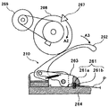
図7及び図8はそれぞれ綴じ具210の構成及び動作の一例を示す説明図である。図7は、圧着歯261が開いた状態の綴じ具210及びその駆動機構の一例を示す説明図であり、図8は、圧着歯261が閉じた状態の綴じ具210及びその駆動機構の一例を示す説明図である。なお、綴じ具210の構成は、図7及び図8の構成に限定されるものではない。 7 and 8 are explanatory views showing an example of the configuration and operation of the binding tool 210, respectively. FIG. 7 is an explanatory view showing an example of the binding tool 210 with the crimping tooth 261 open and its driving mechanism, and FIG. 8 is an example of the binding tool 210 with the crimping tooth 261 closed and its driving mechanism. It is explanatory drawing which shows. The configuration of the binding tool 210 is not limited to the configurations of FIGS. 7 and 8.

図7において、圧着歯261は上圧着歯261aと下圧着歯261bとを有し、噛み合う形状をしている。上圧着歯261aは、可動リンク部材263の先端に組み付けられている。下圧着歯261bは、上圧着歯261aと対向するように固定リンク部材264に組み付けられている。可動リンク部材263は、加圧レバー262の回動によって圧着歯261が互いに接離するように構成されている。加圧レバー262は、図8中矢印A2方向に回転するカム266により、図8中矢印A3方向に回動する。このカム266は駆動モータ265より駆動力を与えられ回転し、カムホームポジションセンサ267の検知情報に基づき、その検知位置に位置するように制御される。カムホームポジションセンサ267の検知位置をカム266のホームポジション(待機位置)とし、この位置で一対の圧着歯261は開いた状態となっている。 In FIG. 7, the crimping tooth 261 has an upper crimping tooth 261a and a lower crimping tooth 261b, and has a shape in which they mesh with each other. The upper crimping tooth 261a is assembled to the tip of the movable link member 263. The lower crimping tooth 261b is assembled to the fixed link member 264 so as to face the upper crimping tooth 261a. The movable link member 263 is configured such that the crimp teeth 261 are brought into contact with each other by the rotation of the pressurizing lever 262. The pressurizing lever 262 is rotated in the direction of arrow A3 in FIG. 8 by a cam 266 that rotates in the direction of arrow A2 in FIG. The cam 266 is given a driving force by the drive motor 265 to rotate, and is controlled to be located at the detection position based on the detection information of the cam home position sensor 267. The detection position of the cam home position sensor 267 is set to the home position (standby position) of the cam 266, and the pair of crimp teeth 261 is in an open state at this position.

用紙を綴じるときは、図8に示すように動作する。一対の圧着歯261が開いた状態で、その間に用紙Pを挿入し、駆動モータ265の回転によってカム266を図8中矢印A2方向へ回転させる。そのカム面の変位によって加圧レバー262は図中矢印A3方向に回動する。その回転力は、てこを利用した可動リンク部材263を介して力を増し、その端部の上圧着歯261aに伝わる。カム266が一定量だけ回転した時点で上圧着歯261aと下圧着歯261bとは噛み合い、用紙Pを狭持する。この狭持によって、用紙Pは変形加圧され、隣接した用紙同士の繊維が絡み合い綴じられる。その後、駆動モータ265は逆回転し、カムホームポジションセンサ267の検知位置で停止する。また、加圧レバー262はバネ性を有しており過負荷が加わったときは撓み、その過負荷を逃がすようになっている。 When binding the paper, it operates as shown in FIG. With the pair of crimping teeth 261 open, the paper P is inserted between them, and the cam 266 is rotated in the direction of arrow A2 in FIG. 8 by the rotation of the drive motor 265. The pressure lever 262 rotates in the direction of arrow A3 in the figure due to the displacement of the cam surface. The rotational force increases the force via the movable link member 263 using a lever, and is transmitted to the upper crimping tooth 261a at the end thereof. When the cam 266 rotates by a certain amount, the upper crimping tooth 261a and the lower crimping tooth 261b mesh with each other to hold the paper P tightly. Due to this narrowing, the paper P is deformed and pressurized, and the fibers of adjacent papers are entangled and bound. After that, the drive motor 265 rotates in the reverse direction and stops at the detection position of the cam home position sensor 267. Further, the pressurizing lever 262 has a spring property and bends when an overload is applied, so that the overload is released.

上記図7及び図8で示す構成の綴じ具210において、用紙Pを変形加圧するように挾持する一対の圧着歯261が噛み合う力である綴じ力が変化し、用紙同士の繊維が絡み合って用紙束が綴じられるときの綴じ強度が変化する。一対の圧着歯261が噛み合うときの綴じ力は、カム266を介して加圧レバー262を回動させるときの回転力(トルク)、すなわち、駆動モータ265で発生するトルク(力のモーメント)によって変化する。駆動モータ265で発生するトルクは、駆動モータ265に供給されるモータ電流に応じて変化する。従って、駆動モータ265に供給されるモータ電流を制御することにより、本綴じモード及び仮綴じモードなどの綴じモードに応じて、綴じ具210の綴じ力を変更し、用紙束の綴じ強度を変更することができる。 In the binding tool 210 having the configurations shown in FIGS. 7 and 8 above, the binding force, which is the meshing force of the pair of crimping teeth 261 holding the paper P so as to deform and pressurize, changes, and the fibers of the papers are entangled with each other to form a bundle of papers. The binding strength when the is bound changes. The binding force when the pair of crimp teeth 261 mesh with each other changes depending on the rotational force (torque) when the pressurizing lever 262 is rotated via the cam 266, that is, the torque (moment of force) generated by the drive motor 265. To do. The torque generated by the drive motor 265 changes according to the motor current supplied to the drive motor 265. Therefore, by controlling the motor current supplied to the drive motor 265, the binding force of the binding tool 210 is changed and the binding strength of the paper bundle is changed according to the binding mode such as the main binding mode and the temporary binding mode. be able to.

次に、用紙処理装置201の綴じ動作の一例について説明する。
図9〜図17は本例の綴じ動作を実行しているときの用紙処理装置201の平面図及び正面図である。図9〜図17それぞれにおいて、分図(a)は用紙処理装置201の平面図であり、分図(b)は用紙処理装置201の正面図である。
Next, an example of the binding operation of the paper processing device 201 will be described.
9 to 17 are a plan view and a front view of the paper processing apparatus 201 when the binding operation of this example is being executed. 9 to 17, each of FIGS. 9 to 17 shows a plan view of the paper processing device 201, and a front view of the paper processing device 201.

まず、図9(a)及び(b)において、画像形成装置101から用紙の出力が開始されると、各部はホームポジションに移動し、初期化処理(イニシャル処理)を完了する。 First, in FIGS. 9A and 9B, when the output of the paper is started from the image forming apparatus 101, each part moves to the home position and completes the initialization process (initial process).

次に、図10(a)及び(b)において、画像形成装置101から出力される用紙Pが用紙処理装置201に搬入される前に、用紙処理装置201は、動作モードの情報と用紙Pの情報を受け取り、それらの情報に基づき、受入れ待機状態になる。なお、本実施形態における動作モードは、ストレートモード、シフトモード及び綴じモードであるが、これに限定されるものではない。 Next, in FIGS. 10A and 10B, before the paper P output from the image forming apparatus 101 is carried into the paper processing apparatus 201, the paper processing apparatus 201 receives the operation mode information and the paper P. Receives information, and based on that information, enters the acceptance standby state. The operation modes in the present embodiment are, but are not limited to, a straight mode, a shift mode, and a binding mode.

ここで、ストレートモード、シフトモードのときの用紙処理装置201の動作について、説明する。 Here, the operation of the paper processing apparatus 201 in the straight mode and the shift mode will be described.

まず、ストレートモードのときの用紙処理装置201の動作について説明する。
ストレートモードの情報と用紙Pの情報を受け取った用紙処理装置201は、ストレートモードの受入れ待機状態になる。具体的には、受け入れた用紙Pを所定の搬送方向(図中の左方向)に搬送するように、入口ローラ対203及び排紙駆動ローラ205aがそれぞれ所定の回転方向の回転を開始するのである。このような受け入れ待機状態の用紙処理装置201に画像形成装置101の排紙ローラ102の回転により用紙Pが送り込まれる。用紙処理装置201に送り込まれた用紙Pは、入口ローラ対203、排紙駆動ローラ205aと排紙従動ローラ205bとからなる排紙ローラ対により順次搬送され、排出される。そして、最終紙が排出されると、入口ローラ対203、排紙駆動ローラ205aは停止する。
First, the operation of the paper processing apparatus 201 in the straight mode will be described.
The paper processing apparatus 201 that has received the information on the straight mode and the information on the paper P goes into the acceptance standby state in the straight mode. Specifically, the inlet roller pair 203 and the paper ejection drive roller 205a each start rotation in a predetermined rotation direction so that the received paper P is conveyed in a predetermined transfer direction (left direction in the drawing). .. The paper P is fed to the paper processing device 201 in the acceptance standby state by the rotation of the paper ejection roller 102 of the image forming device 101. The paper P fed to the paper processing device 201 is sequentially conveyed and discharged by a paper ejection roller pair including an inlet roller pair 203, a paper ejection drive roller 205a, and a paper ejection driven roller 205b. Then, when the final paper is ejected, the inlet roller pair 203 and the paper ejection drive roller 205a are stopped.

次に、シフトモードにおける用紙処理装置201の動作について説明する。
シフトモードの情報と用紙Pの情報を受け取った用紙処理装置201は、シフトモードの受入れ待機状態になる。具体的には、ストレートモードと同様に、受け入れた用紙Pを所定の搬送方向(図中の左方向)に搬送するように、入口ローラ対203及び排紙駆動ローラ205aがそれぞれ所定の回転方向の回転を開始するのである。このような受け入れ待機状態の用紙処理装置201に画像形成装置101から用紙Pが送り込まれる。用紙処理装置201に送り込まれた用紙は、ストレートモードと同様、入口ローラ対203、排紙ローラ対により搬送されていく。次に、用紙の後端が入口ローラ対203を抜けたところで、シフトカム207が一定量回転し、排紙駆動ローラ205aが軸方向に移動する。このとき、用紙Pも排紙駆動ローラ205aの移動とともに移動する。用紙Pが排出されるとシフトカム207はホームポジションに復帰するべく回転し、次の用紙にそなえる。この排紙駆動ローラ205aの動作を同じ「部」の用紙が排出されるまで繰り返す。次の「部」の用紙が搬入された場合は、シフトカム207は先程とは逆回転方向に回転し、用紙は反対側に移動して排出される。
Next, the operation of the paper processing apparatus 201 in the shift mode will be described.
The paper processing apparatus 201 that has received the shift mode information and the paper P information is put into the shift mode acceptance standby state. Specifically, as in the straight mode, the inlet roller pair 203 and the paper ejection drive roller 205a are respectively in the predetermined rotation direction so as to convey the received paper P in the predetermined transfer direction (left direction in the drawing). It starts to rotate. The paper P is fed from the image forming apparatus 101 to the paper processing device 201 in the acceptance standby state. The paper fed to the paper processing device 201 is conveyed by the inlet roller pair 203 and the paper discharge roller pair as in the straight mode. Next, when the rear end of the paper passes through the inlet roller pair 203, the shift cam 207 rotates by a certain amount, and the paper ejection drive roller 205a moves in the axial direction. At this time, the paper P also moves with the movement of the paper ejection drive roller 205a. When the paper P is ejected, the shift cam 207 rotates to return to the home position and prepares for the next paper. The operation of the paper ejection drive roller 205a is repeated until the same "part" of paper is ejected. When the next "part" of paper is carried in, the shift cam 207 rotates in the direction opposite to the previous rotation, and the paper moves to the opposite side and is ejected.

一方、綴じモードの情報と用紙Pの情報を受け取った用紙処理装置201は、綴じモードの受入れ待機状態になる。綴じモードの受入れ待機状態では、入口ローラ203は停止し、受け入れた用紙Pを所定の搬送方向(図中の左方向)に搬送するように、排紙ローラ205が図中矢印A6方向の回転を開始する。また、綴じ具210は用紙Pの幅方向端部より一定量退避した待機位置(ホームポジション)に移動して待機する。 On the other hand, the paper processing apparatus 201 that has received the binding mode information and the paper P information is put into the acceptance standby state of the binding mode. In the acceptance standby state in the binding mode, the inlet roller 203 stops, and the paper ejection roller 205 rotates in the arrow A6 direction in the drawing so as to convey the received paper P in a predetermined conveying direction (left direction in the drawing). Start. Further, the binding tool 210 moves to a standby position (home position) retracted by a certain amount from the widthwise end of the paper P and stands by.

その後、用紙Pが用紙処理装置201に搬入されると、その用紙Pの先端が入口センサ202で検知される。この検知されたタイミングから一定距離(用紙Pの先端が入口ローラ203のニップに突き当たって一定量の撓みを生じさせる距離)だけ用紙Pが搬送される。その搬送の後、入口ローラ203が回転し始める。これにより、用紙Pのスキューが補正される。 After that, when the paper P is carried into the paper processing device 201, the tip of the paper P is detected by the inlet sensor 202. From this detected timing, the paper P is conveyed by a certain distance (the distance at which the tip of the paper P abuts against the nip of the inlet roller 203 and causes a certain amount of bending). After the transfer, the inlet roller 203 starts to rotate. As a result, the skew of the paper P is corrected.

次に、図11(a)及び(b)において、用紙Pの後端を検知した入口センサ202の検知情報を基準にして用紙Pの搬送量がカウントされ、その用紙Pの位置情報が把握されている。用紙Pの後端が入口ローラ203のニップを通過したら、入口ローラ203は次の用紙受入れのために停止する。それと同時期に、シフトカム207が図11(a)中の矢印A7方向(時計方向)に回転し、用紙Pとともに排紙ローラ205は軸方向に移動を開始する。すると、用紙Pは図11(a)中の矢印A8方向に斜行しながら搬送される。その後、綴じ具210に併設または組込まれた用紙端センサ220が用紙Pを検知すると、シフトカム207は停止した後、逆転する。このシフトカム207の逆回転は、用紙端センサ220が非検知状態になったときに停止する。以上の動作が完了し、用紙Pの後端が分岐爪204の先端を通過した所定の位置で、排紙ローラ205の図中矢印A9方向の回転が停止する。 Next, in FIGS. 11A and 11B, the amount of the paper P conveyed is counted based on the detection information of the inlet sensor 202 that detects the rear end of the paper P, and the position information of the paper P is grasped. ing. When the rear end of the paper P passes through the nip of the inlet roller 203, the inlet roller 203 stops for the next paper acceptance. At the same time, the shift cam 207 rotates in the direction of arrow A7 (clockwise) in FIG. 11A, and the paper ejection roller 205 starts moving in the axial direction together with the paper P. Then, the paper P is conveyed while skewing in the direction of the arrow A8 in FIG. 11 (a). After that, when the paper edge sensor 220 attached to or incorporated in the binding tool 210 detects the paper P, the shift cam 207 stops and then reverses. The reverse rotation of the shift cam 207 is stopped when the paper edge sensor 220 is in the non-detection state. When the above operation is completed and the rear end of the paper P passes the tip of the branch claw 204, the rotation of the paper ejection roller 205 in the direction of arrow A9 in the drawing is stopped.

次に、図12(a)及び(b)において、分岐爪204が図12(b)中の矢印A10方向(時計方向)に回転し、搬送路が切り換えられる。その後、排紙ローラ205が図中矢印A11方向(反時計方向)に逆回転し、用紙Pの後端部が分岐路241に搬入されるように用紙Pが図中矢印A12に搬送される。この搬送により、用紙Pが綴じ処理用トレイ243の突き当て面242に突き当てられて揃えられ、排紙ローラ205が停止する。ここで、排紙ローラ205は、用紙Pが突き当たるとスリップするように弱い搬送力となるように設定されている。 Next, in FIGS. 12A and 12B, the branch claw 204 rotates in the direction of arrow A10 (clockwise) in FIG. 12B, and the transport path is switched. After that, the paper ejection roller 205 rotates in the reverse direction in the direction of arrow A11 (counterclockwise) in the drawing, and the paper P is conveyed to the arrow A12 in the drawing so that the rear end portion of the paper P is carried into the branch path 241. By this transfer, the paper P is abutted against the abutting surface 242 of the binding processing tray 243 and aligned, and the paper ejection roller 205 is stopped. Here, the paper ejection roller 205 is set to have a weak carrying force so as to slip when the paper P hits the paper.

次に、図13(a)及び(b)において、分岐爪204が図13(b)中の矢印A13方向(反時計方向)に回転し、分岐路241にある用紙Pの後端が分岐爪204の接触面で強力に押さえられ、待機する。後続の用紙P’が画像形成装置101から出力されてくると、1枚目の用紙Pと同様に、入口ローラ203で用紙P’のスキュー補正を行なう動作をする。また、入口ローラ203の回転が開始するのと同時期に、用紙を搬送する回転方向(図中A6方向)に排紙ローラ205も回転を開始する。 Next, in FIGS. 13 (a) and 13 (b), the branch claw 204 rotates in the direction of arrow A13 (counterclockwise) in FIG. 13 (b), and the rear end of the paper P in the branch path 241 is the branch claw. It is strongly pressed by the contact surface of 204 and stands by. When the subsequent paper P'is output from the image forming apparatus 101, the inlet roller 203 performs an operation of skew-correcting the paper P'as in the case of the first paper P. Further, at the same time as the rotation of the inlet roller 203 starts, the paper ejection roller 205 also starts rotating in the rotation direction (A6 direction in the drawing) for conveying the paper.

次に、図14(a)及び(b)において、2枚目以降の用紙P’’、・・・についても、前述の図11及び図12の動作を実施し、順次用紙を狙いの位置に移動させ重ね合わせることで整合状態の用紙束Psを搬送路内にスタックする。 Next, in FIGS. 14A and 14B, the operations of FIGS. 11 and 12 described above are performed for the second and subsequent sheets P'', ..., And the sheets are sequentially placed at the target positions. By moving and overlapping, the aligned paper bundles Ps are stacked in the transport path.

次に、図15(a)及び(b)において、最終紙を整合状態の用紙束Psに重ね合わせる動作が完了したら、用紙束Psを一定量だけ搬送させるように排紙ローラ205が図15(b)中の矢印A14方向(時計方向)に回転して停止する。この排紙ローラ205の動作により、用紙の後端を突き当て面242に突き当てたときに発生した撓みを無くすことができる。その後、分岐爪204は図15(b)中の矢印A15方向(時計方向)に回転して先端の向きが切り換えられ、用紙束Psにかけていた押さえ力が開放される。 Next, in FIGS. 15A and 15B, when the operation of superimposing the final paper on the aligned paper bundle Ps is completed, the paper ejection roller 205 transfers the paper bundle Ps by a certain amount in FIG. b) Rotate in the direction of arrow A14 (clockwise) in the middle and stop. By the operation of the paper ejection roller 205, it is possible to eliminate the bending generated when the rear end of the paper is abutted against the abutting surface 242. After that, the branch claw 204 rotates in the direction of arrow A15 (clockwise) in FIG. 15B to switch the direction of the tip, and the pressing force applied to the paper bundle Ps is released.

次に、図16(a)及び(b)において、排紙ローラ205が図矢印A16方向に回転することにより、綴じ具210の圧着歯261の位置と用紙の加工位置(綴じ位置)とが一致する距離分だけ用紙束Psが搬送され停止する。これにより、用紙搬送方向における綴じ具210の圧着歯261の位置と用紙の加工位置(綴じ位置)とが合せられる。また、綴じ具210の圧着歯261の位置と用紙の加工位置とが一致する距離分だけ、綴じ具210が図16(a)中の矢印A17方向に移動して停止する。これにより、用紙幅方向における綴じ具210の圧着歯261の位置と用紙の加工位置(綴じ位置)とが合わせられる。このとき、分岐爪204は図16(b)中の矢印A18方向(反時計方向)に回転して先端の向きが切り換えられ、用紙受入れ状態に復帰する。その後、綴じ具210の駆動モータ265がONされ、圧着歯261によって用紙束Psが加圧されて絞りが行われることで、各用紙Pの繊維が互いに絡んで用紙同士が結合され、用紙束Psが綴じられる。 Next, in FIGS. 16A and 16B, the position of the crimping tooth 261 of the binding tool 210 and the processing position (binding position) of the paper coincide with each other by rotating the paper ejection roller 205 in the direction of arrow A16. Paper bundles Ps are conveyed and stopped by the distance to be used. As a result, the position of the crimping tooth 261 of the binding tool 210 in the paper transport direction and the processing position (binding position) of the paper are aligned. Further, the binding tool 210 moves in the direction of arrow A17 in FIG. 16A and stops by a distance that coincides with the position of the crimping tooth 261 of the binding tool 210 and the processing position of the paper. As a result, the position of the crimping tooth 261 of the binding tool 210 in the paper width direction and the processing position (binding position) of the paper are aligned. At this time, the branch claw 204 rotates in the direction of arrow A18 (counterclockwise direction) in FIG. 16B to switch the direction of the tip and return to the paper receiving state. After that, the drive motor 265 of the binding tool 210 is turned on, and the paper bundle Ps is pressed by the crimping teeth 261 to perform drawing, so that the fibers of the paper P are entwined with each other and the paper bundles Ps are bonded to each other. Is bound.

次に、図17(a)及び(b)において、排紙ローラ205が図中矢印A16方向に更に回転すると、綴じた用紙束Psが排出される。そして、用紙束Psの排出後に、シフトカム207が図中A19方向に回転してホームポジションに復帰し、綴じ具210が図中矢印A20方向に移動してホームポジションに復帰する。以上により、用紙束Psの綴じ処理の動作を完了する。 Next, in FIGS. 17A and 17B, when the paper ejection roller 205 further rotates in the direction of arrow A16 in the drawing, the bound paper bundle Ps is ejected. Then, after the paper bundle Ps is ejected, the shift cam 207 rotates in the direction A19 in the drawing and returns to the home position, and the binding tool 210 moves in the direction of the arrow A20 in the drawing and returns to the home position. As described above, the operation of the binding process of the paper bundle Ps is completed.

図18は、圧着綴じ方法の説明図である。
図18(a)に示すように、綴じ具210は、凹凸形状がある上圧着歯261aと下圧着歯261bとが、用紙束Psを挟むように対向する位置に配置されている。そして、図18(b)に示すように、少なくとも一方の圧着歯を動かし、上圧着歯261aと下圧着歯261bとを用紙束Psを挟み込むように噛み合わせて用紙束Psに圧力を掛ける。その圧力を大きくしていくと、紙の繊維が絡まり、用紙束Psの綴じが完了する。この圧着綴じでは、凹凸の嵌合により用紙束Psを圧接絞りすることにより用紙間の繊維の絡まりや固着により用紙束Psを綴じることが可能となる。
FIG. 18 is an explanatory diagram of a crimp binding method.
As shown in FIG. 18A, in the binding tool 210, the upper crimping teeth 261a and the lower crimping teeth 261b having an uneven shape are arranged at positions facing each other so as to sandwich the paper bundle Ps. Then, as shown in FIG. 18B, at least one of the crimping teeth is moved, and the upper crimping tooth 261a and the lower crimping tooth 261b are engaged with each other so as to sandwich the paper bundle Ps, and pressure is applied to the paper bundle Ps. As the pressure is increased, the fibers of the paper are entangled and the binding of the paper bundle Ps is completed. In this crimp binding, the paper bundle Ps can be bound by pressure-welding and squeezing the paper bundle Ps by fitting the unevenness, and the paper bundle Ps can be bound by the entanglement and sticking of the fibers between the papers.

その後、図18(c)のように再び少なくとも一方の圧着歯を動かし、上圧着歯261aと下圧着歯261bとを離間させる。圧着綴じされた用紙束Psには、図18(d)に示すように凹凸形状が転写される。 Then, as shown in FIG. 18C, at least one crimping tooth is moved again to separate the upper crimping tooth 261a and the lower crimping tooth 261b. As shown in FIG. 18D, the concave-convex shape is transferred to the pressure-bonded paper bundle Ps.

本実施形態では、上圧着歯261a及び下圧着歯261bの凹凸形状には、任意の角度の斜面部がある。また、上圧着歯261aと下圧着歯261bとが噛み合ったときに、上圧着歯261aの頂部と下圧着歯261bの底部とが接触しないようになっている。これにより、上圧着歯261a及び下圧着歯261bの凹凸形状の斜面部で用紙束Psを圧着することになる。図18(d)に示すように、用紙束Psの凹部6aは、上圧着歯261aの凸部により絞られた伸びた部分となり、用紙束Psの凸部6bは、下圧着歯261bの凸部により絞られた伸びた部分となる。また、用紙束Psの凹凸形状部の斜面部6cは、圧着により綴じられた部分となる。 In the present embodiment, the uneven shape of the upper crimping tooth 261a and the lower crimping tooth 261b has a slope portion having an arbitrary angle. Further, when the upper crimping tooth 261a and the lower crimping tooth 261b mesh with each other, the top of the upper crimping tooth 261a and the bottom of the lower crimping tooth 261b do not come into contact with each other. As a result, the paper bundle Ps is crimped on the uneven slope portion of the upper crimping tooth 261a and the lower crimping tooth 261b. As shown in FIG. 18D, the concave portion 6a of the paper bundle Ps is an extended portion narrowed by the convex portion of the upper crimping tooth 261a, and the convex portion 6b of the paper bundle Ps is the convex portion of the lower crimping tooth 261b. It becomes a stretched part narrowed down by. Further, the slope portion 6c of the uneven shape portion of the paper bundle Ps is a portion bound by crimping.

次に、本実施形態の特徴部である一対の圧着歯の凹凸形状について説明する。上圧着歯261aの形状と下圧着歯261bの形状は、同じであるので、以下の説明では、下圧着歯261bについてのみ説明する。 Next, the uneven shape of the pair of crimping teeth, which is a feature of the present embodiment, will be described. Since the shape of the upper crimping tooth 261a and the shape of the lower crimping tooth 261b are the same, only the lower crimping tooth 261b will be described in the following description.

図19は、下圧着歯261bの平面図であり、図20は、図19のA方向から見た図であり、図21は、図19のB方向から見た図である。図20、図21における点線は、上圧着歯261aであり、一点鎖線は、用紙束Psを示している。
図19に示すように、下圧着歯261bは、複数の凸部70bを所定の間隔をあけて並べて配置することにより、凹凸形状を形成している。
19 is a plan view of the lower crimping tooth 261b, FIG. 20 is a view seen from the A direction of FIG. 19, and FIG. 21 is a view seen from the B direction of FIG. The dotted line in FIGS. 20 and 21 is the upper crimping tooth 261a, and the alternate long and short dash line indicates the paper bundle Ps.
As shown in FIG. 19, the lower crimping tooth 261b forms an uneven shape by arranging a plurality of convex portions 70b side by side at predetermined intervals.

各凸部70bは、四角錐を、高さ方向中央部付近で、底面と平行に切ったような形状をしており、頂部71bが用紙束の紙面と平行な面となっている。なお、ここで言う「紙面と平行な面」とは、紙面と略平行な面を含むものであり、図20に示すように、わずかに山形状となった面を含むものである。また、各凸部70bの底面の各辺を底辺とし、頂面の一辺を頂辺とする4つの側面は、用紙束Psの紙面に対して傾斜する斜面部72bとなっている。 Each convex portion 70b has a shape like a quadrangular pyramid cut in parallel with the bottom surface near the central portion in the height direction, and the top portion 71b is a surface parallel to the paper surface of the paper bundle. The term "plane parallel to the paper surface" as used herein includes a surface substantially parallel to the paper surface, and as shown in FIG. 20, includes a surface having a slightly mountain-shaped shape. Further, the four side surfaces having each side of the bottom surface of each convex portion 70b as the bottom side and one side of the top surface as the top side are slope portions 72b that are inclined with respect to the paper surface of the paper bundle Ps.

また、図20におけるBは、圧着高さであり、下圧着歯261bの斜面部72bと、上圧着歯261aの斜面部72aとの接触部分を示している。また、図20における矢印Zは、凸部70bにより用紙が伸ばされる部分である。また、図21におけるθ2は、めくり側すくい角であり、本実施形態では、60°とした。また、図21におけるSは、用紙が圧着される圧着面積である。 Further, B in FIG. 20 is the crimping height, and indicates the contact portion between the slope portion 72b of the lower crimping tooth 261b and the slope portion 72a of the upper crimping tooth 261a. Further, the arrow Z in FIG. 20 is a portion where the paper is stretched by the convex portion 70b. Further, θ2 in FIG. 21 is a rake angle on the turning side, and is set to 60 ° in the present embodiment. Further, S in FIG. 21 is a crimping area where the paper is crimped.

図22は、圧着綴じ時における用紙束Psの挙動について説明する図である。
図22(a)に示すように、一方の圧着歯を動かし、上圧着歯261aと下圧着歯261bとを用紙束Psを挟み込むように噛み合わせていくと、用紙が各圧着歯の凸部の頂部71a,71bにより絞られて伸びていく。本実施形態においては、各圧着歯の凸部の頂部71a,71bを、用紙束Psの紙面に平行な面としているので、各圧着歯の凸部の頂部71a,71bと用紙束Psとの圧力を低く抑えることができる。これにより、凸部の頂部71a,71bにより用紙束Psが破れてしまうのを抑制することができる。
FIG. 22 is a diagram illustrating the behavior of the paper bundle Ps during crimp binding.
As shown in FIG. 22A, when one of the crimping teeth is moved and the upper crimping tooth 261a and the lower crimping tooth 261b are engaged so as to sandwich the paper bundle Ps, the paper is formed on the convex portion of each crimping tooth. It is squeezed and stretched by the tops 71a and 71b. In the present embodiment, since the top portions 71a and 71b of the convex portions of the crimping teeth are parallel to the paper surface of the paper bundle Ps, the pressure between the top portions 71a and 71b of the convex portions of the crimping teeth and the paper bundle Ps. Can be kept low. As a result, it is possible to prevent the paper bundle Ps from being torn by the top portions 71a and 71b of the convex portion.

また、上圧着歯261aと下圧着歯261bとが噛み合う過程において、用紙束Psの上圧着歯261aの凸部70aの側面である斜面部72a、下圧着歯261bの斜面部72bとに挟まれた箇所(図22(a)の丸で囲った箇所)が、圧延されることにより繊維同士の絡みが生じる。 Further, in the process of meshing the upper crimping tooth 261a and the lower crimping tooth 261b, the paper bundle Ps was sandwiched between the slope portion 72a which is the side surface of the convex portion 70a of the upper crimping tooth 261a and the slope portion 72b of the lower crimping tooth 261b. When the portion (the portion circled in FIG. 22A) is rolled, the fibers are entangled with each other.

本実施形態においては、用紙束Psの紙面に対して傾斜した斜面部72a,72bで用紙が圧着される。下圧着歯261bの斜面部72bから用紙束Psに加わる鉛直上方向の加圧力を、斜面部72bと直交する方向と、斜面部72bと平行な方向とに分けたときの斜面部72bと平行な方向の分力の向きは、下圧着歯261bの頂部71bに向かう方向である。同様に、上圧着歯261aの斜面部72aから用紙束Psに加わる鉛直下方向の加圧力の斜面部72aと平行な方向の分力の向きは、上圧着歯261aの頂部71aに向かう方向である。従って、図中丸で囲った用紙束Psの圧着箇所では、下圧着歯側の用紙は、斜面部72bに沿って上側へ移動し、上圧着歯側の用紙は、斜面部72aに沿って下側へ移動する。これにより、用紙束Psの圧着箇所で、用紙のすり潰しが発生し、より用紙同士の繊維を絡み合わせることができ、強い綴じ力で綴じることができる。 In the present embodiment, the paper is crimped at the slopes 72a and 72b inclined with respect to the paper surface of the paper bundle Ps. The vertical upward pressing force applied to the paper bundle Ps from the slope portion 72b of the lower crimping tooth 261b is parallel to the slope portion 72b when divided into a direction orthogonal to the slope portion 72b and a direction parallel to the slope portion 72b. The direction of the component force in the direction is the direction toward the top 71b of the lower crimping tooth 261b. Similarly, the direction of the component force in the direction parallel to the slope portion 72a of the vertically downward pressing force applied to the paper bundle Ps from the slope portion 72a of the upper crimping tooth 261a is the direction toward the top portion 71a of the upper crimping tooth 261a. .. Therefore, at the crimping portion of the paper bundle Ps circled in the drawing, the paper on the lower crimping tooth side moves upward along the slope portion 72b, and the paper on the upper crimping tooth side moves downward along the slope portion 72a. Move to. As a result, the paper is ground at the crimping portion of the paper bundle Ps, the fibers of the paper can be more entangled with each other, and the paper can be bound with a strong binding force.

図22(b)に示すように、下死点まで上圧着歯261aを移動させたとき、下圧着歯261bの凸部70bの頂部71bと上圧着歯261aの凹部の底部73aとの間、および、上圧着歯261aの凸部70aの頂部71aと下圧着歯261bの凹部の底部73bとの間にそれぞれ隙間Sが生じるように構成している。上述したように、本実施形態では、図21(a)の丸で囲った用紙束Psの圧着箇所で、下圧着歯側の用紙は、斜面部72bに沿って上側へ移動し、上圧着歯側の用紙は、斜面部72aに沿って下側へ移動する。このように、圧着箇所で用紙が擦れ動くため、図22(b)に示すように、各凸部の頂部71a,71bと凹部の底部73a,73bとの隙間Sで用紙が波打つように撓む。本実施形態とは異なり、各凸部の頂部が、凹部の底部に接触する構成とし、隙間Sが形成されない構成とした場合は、各凸部の頂部と凹部の底部と間で生じた撓みが、最終的には、押しつぶされることなり、用紙にしわ等のダメージが生じることになる。一方、本実施形態においては、下死点まで上圧着歯261aを移動させたとき、各凸部の頂部71a,71bと凹部の底部73a,73bとに隙間Sが生じる構成であるので、撓みが押しつぶされることがない。逆に、凸部70a,70bによる絞りにより適度に加圧され、各凸部の頂部71a,71bと凹部の底部73a,73bと間の隙間Sで、用紙の繊維同士を絡み合わせることができ、用紙束を強く綴じることができる。 As shown in FIG. 22B, when the upper crimping tooth 261a is moved to the bottom dead center, between the top 71b of the convex portion 70b of the lower crimping tooth 261b and the bottom portion 73a of the concave portion of the upper crimping tooth 261a, and A gap S is formed between the top portion 71a of the convex portion 70a of the upper crimping tooth 261a and the bottom portion 73b of the concave portion of the lower crimping tooth 261b. As described above, in the present embodiment, at the crimping portion of the paper bundle Ps circled in FIG. 21A, the paper on the lower crimping tooth side moves upward along the slope portion 72b, and the upper crimping tooth The paper on the side moves downward along the slope portion 72a. Since the paper rubs at the crimping portion in this way, as shown in FIG. 22B, the paper bends in a wavy manner in the gap S between the tops 71a and 71b of the convex portions and the bottoms 73a and 73b of the concave portions. .. Unlike the present embodiment, when the top of each convex portion is in contact with the bottom of the concave portion and the gap S is not formed, the deflection generated between the top of each convex portion and the bottom of the concave portion is generated. Eventually, it will be crushed and damage such as wrinkles will occur on the paper. On the other hand, in the present embodiment, when the upper crimping tooth 261a is moved to the bottom dead center, a gap S is formed between the top portions 71a and 71b of each convex portion and the bottom portions 73a and 73b of the concave portion, so that the deflection occurs. Will not be crushed. On the contrary, it is appropriately pressurized by the drawing by the convex portions 70a and 70b, and the fibers of the paper can be entangled with each other in the gap S between the top portions 71a and 71b of the convex portions and the bottom portions 73a and 73b of the concave portions. Paper bundles can be bound tightly.

また、斜面部72a,72bで用紙束Psに圧力を加えているときに、擦れ動いた用紙が、隙間Sへ移動することができる。これにより、圧着箇所で用紙を良好にすり潰すことができ、良好な綴じ力を得ることができる。 Further, when pressure is applied to the paper bundle Ps on the slope portions 72a and 72b, the rubbed paper can move to the gap S. As a result, the paper can be satisfactorily ground at the crimped portion, and a good binding force can be obtained.

本実施形態においては、凸部70a,70bで用紙を絞り伸ばしつつ図22(a)の丸で囲った圧着箇所で用紙を擦りつぶすことで、紙の繊維を絡み合わせて用紙束Psが圧着綴じされる。先の図20に示す、下圧着歯261bの斜面部72bと、上圧着歯261aの斜面部72aとの接触範囲である圧着高さBが長いほど、圧着面積S(図21参照)が増え強固に用紙束を綴じることができる。しかしながら、圧着高さBが長くなるということは、噛み合わせたときの下圧着歯261bの凸部の頂部71bから、上圧着歯261aの凸部の頂部71aまでの長さが長くなる。その結果、用紙がそれだけ伸ばされることになり、用紙の伸びが限界を超え、破れが発生するおそれがある。 In the present embodiment, the paper is squeezed and stretched by the convex portions 70a and 70b, and the paper is crushed at the crimping portion circled in FIG. 22A, so that the fibers of the paper are entangled and the paper bundle Ps is crimp-bound. Will be done. The longer the crimping height B, which is the contact range between the slope portion 72b of the lower crimping tooth 261b and the slope portion 72a of the upper crimping tooth 261a shown in FIG. 20, the larger the crimping area S (see FIG. 21) and the stronger the crimping area S. A bundle of paper can be bound to. However, the longer crimping height B means that the length from the top 71b of the convex portion of the lower crimping tooth 261b to the top 71a of the convex portion of the upper crimping tooth 261a when meshed becomes longer. As a result, the paper is stretched by that amount, and the stretch of the paper exceeds the limit, which may cause tearing.

そこで、本発明者らは鋭意検証試験を行って最適な圧着高さBを見つけた。以下に、本発明者らが行った検証試験について、説明する。 Therefore, the present inventors conducted an diligent verification test to find the optimum crimping height B. The verification test conducted by the present inventors will be described below.

検証試験は、圧着高さBが0.45mmの綴じ具と、圧着高さBが0.6mmの綴じ具と、圧着高さBが0.7mmの綴じ具とを作成し、各綴じ具について綴じ力を測定した。綴じ力は、通常5枚前後の用紙を綴じることが一般的であるので、各綴じ具で、5枚の用紙束を綴じ、その用紙束の綴じ力について測定した。 In the verification test, a binding tool having a crimping height B of 0.45 mm, a binding tool having a crimping height B of 0.6 mm, and a binding tool having a crimping height B of 0.7 mm were prepared, and each binding tool was prepared. The binding force was measured. Since the binding force is generally about 5 sheets of paper, each binding tool binds 5 sheets of paper and measures the binding force of the bundle.

また、各綴じ具のその他の条件は、以下のとおりである。
・加圧力:2000N
・歯数:6歯(凸部の数)
・めくり側すくい角度θ2:60°
In addition, other conditions of each binding tool are as follows.
・ Pressurization: 2000N
・ Number of teeth: 6 teeth (number of convex parts)
・ Turning side rake angle θ2: 60 °

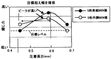
図23は、検証試験の結果を示すグラフである。図23は、用紙束の一枚目の用紙(最上位紙)の綴じ力と、用紙束中央の用紙(上から3枚目の用紙)の綴じ力の検証試験の結果を示している。また、図23は、複数回綴じ力測定を行ったうちの最小値の綴じ力をプロットしている。 FIG. 23 is a graph showing the results of the verification test. FIG. 23 shows the results of a verification test of the binding force of the first sheet of the paper bundle (top paper) and the binding force of the paper at the center of the paper bundle (third sheet from the top). Further, FIG. 23 plots the minimum value of the binding force measured a plurality of times.

図23に示すように、圧着高さBを0.45mm以上にすることで、綴じ力を目標レベル以上にすることができた。また、圧着高さBが0.6mmとき、綴じ力がピークとなり、圧着高さB0.7mmの綴じ具は、圧着高さBが、0.6mmの綴じ具に比べて、綴じ力が低下した。用紙が破れると綴じ力が低下するため、圧着高さBを長くしたにも関わらず、0.6mmよりも綴じ力が低下している圧着高さB0.7mmの綴じ具で綴じられた用紙には、破れが発生していると考えられる As shown in FIG. 23, by setting the crimping height B to 0.45 mm or more, the binding force could be made higher than the target level. Further, when the crimping height B was 0.6 mm, the binding force peaked, and the binding force of the binding tool having the crimping height B 0.7 mm was lower than that of the binding tool having the crimping height B of 0.6 mm. .. Since the binding force decreases when the paper is torn, the binding force is lower than 0.6 mm even though the crimping height B is lengthened. The paper is bound with a binding tool with a crimping height of B0.7 mm. Is considered to be torn

上記検証試験から、少なくとも圧着高さBを、0.45mm以上、0.6mm以下とすることで、用紙が破れることなく、良好な綴じ力が得られることが確認された。 From the above verification test, it was confirmed that by setting at least the crimping height B to 0.45 mm or more and 0.6 mm or less, good binding force can be obtained without tearing the paper.

また、圧着高さが0.45mm以下の場合でも、歯の数(凸部の数)を多くしたり、加圧力を高くしたりすることで、綴じ力を目標レベル以上にすることは可能である。しかしながら、歯数を多くすることにより、綴じ具が大型化し、材料費が嵩み、装置のコストアップに繋がる。また、材料を多く消費することになり、資源を浪費してしまう。また、加圧力を上げる場合は、加圧に必要な駆動源の駆動力を大きくする必要があり、装置の消費電力が増加するというデメリットが生じる。一方、圧着高さを0.45mm以上とすることで、歯数を抑えることができ、材料費を抑えることができ、装置のコストアップを抑えることができる。また、省資源化を図ることができる。また、加圧力を抑えることができ、省エネルギー化を図ることができる。 Even when the crimping height is 0.45 mm or less, it is possible to increase the binding force to the target level or higher by increasing the number of teeth (the number of convex parts) or increasing the pressing force. is there. However, by increasing the number of teeth, the binding tool becomes large, the material cost increases, and the cost of the device increases. In addition, a large amount of material is consumed, which wastes resources. Further, when increasing the pressing force, it is necessary to increase the driving force of the driving source required for pressurizing, which has a demerit that the power consumption of the device increases. On the other hand, by setting the crimping height to 0.45 mm or more, the number of teeth can be suppressed, the material cost can be suppressed, and the cost increase of the device can be suppressed. In addition, resource saving can be achieved. In addition, the pressing force can be suppressed and energy saving can be achieved.

以上に説明したものは一例であり、本発明は、以下の態様毎に特有の効果を奏する。
(態様1)
複数の凹部と複数の凸部とが平行に並んで交互に配置された一対の圧着歯などの圧着部材の互いの凹凸を用紙束を挟んで噛み合せることで用紙束を綴じる圧着綴じ方式の綴じ具210などの用紙綴じ装置において、上記一対の圧着部材いずれも、上記凸部の頂部71a,71bが上記用紙束の紙面に対して平行な面であり、上記凸部における側面が、上記紙面に対して傾斜した斜面部72a,72bなどの傾斜面であり、一対の圧着部材の互いの凹凸をかみ合わせたとき、上記傾斜面同士が接触し、かつ、一方の圧着部材の凸部の頂部71aと他方の圧着部材の凹部の底部73bとの間および他方の圧着部材の凸部の頂部71bと一方の圧着部材の凹部の底部73aとの間いずれにも隙間Sが形成されるよう一対の圧着部材を構成した。
(態様1)によれば、一対の圧着部材を噛み合わせたとき、一対の圧着部材の凸部における側面である傾斜面同士が接触するように構成したので、用紙束は、一対の圧着部材の傾斜面で圧力を受け綴じられる。このとき、一方の圧着部材の凸部の頂部と、他方の圧着部材の凹部の底部との間、他方の圧着部材の凸部の頂部と、一方の圧着部材の凹部の底部との間、いずれも隙間を有している。従って、一方の圧着部材の凸部の頂部と他方の圧着部材の凹部の底部との間にしか隙間がない特許文献1に記載の構成に比べて、紙の繊維の負荷をより低減することができる。これにより、繊維の限界を超えた伸長を特許文献1に比べて回避することができ、特許文献1に比べて破れずに繊維同士を絡み合せることができる。
また、両方の圧着部材の凸部の頂部が、用紙束の紙面に対して平行な面となっているので、用紙束の一方の圧着歯の凸部の頂部と接触する箇所、及び、用紙束の他方の圧着歯の凸部と接触する箇所いずれも面接触となり圧力が集中するのが防止される。これにより、圧着綴じの際に用紙束が破れてしまうのを抑制することができる。
The above description is an example, and the present invention exerts a unique effect for each of the following aspects.
(Aspect 1)
A crimp binding method for binding a bundle of paper by engaging the unevenness of a pair of crimping members such as a pair of crimping teeth in which a plurality of concave portions and a plurality of convex portions are arranged in parallel and alternately with the paper bundle sandwiched between them. In a paper binding device such as the tool 210, in each of the pair of crimping members, the top portions 71a and 71b of the convex portion are parallel to the paper surface of the paper bundle, and the side surface of the convex portion is on the paper surface. On the other hand, it is an inclined surface such as inclined slope portions 72a and 72b, and when the unevenness of the pair of crimping members is engaged with each other, the inclined surfaces are in contact with each other and with the top portion 71a of the convex portion of one crimping member. A pair of crimping members so that a gap S is formed between the bottom portion 73b of the concave portion of the other crimping member and between the top portion 71b of the convex portion of the other crimping member and the bottom portion 73a of the concave portion of the one crimping member. Was configured.
According to (Aspect 1), when the pair of crimping members are meshed with each other, the inclined surfaces which are the side surfaces of the convex portions of the pair of crimping members are in contact with each other. It is bound under pressure on an inclined surface. At this time, either between the top of the convex portion of one crimping member and the bottom of the concave portion of the other crimping member, or between the top of the convex portion of the other crimping member and the bottom of the concave portion of one crimping member. Also has a gap. Therefore, the load on the paper fibers can be further reduced as compared with the configuration described in Patent Document 1 in which there is a gap only between the top of the convex portion of one crimping member and the bottom of the concave portion of the other crimping member. it can. As a result, elongation exceeding the limit of the fiber can be avoided as compared with Patent Document 1, and the fibers can be entangled with each other without being torn as compared with Patent Document 1.
Further, since the tops of the convex portions of both crimping members are parallel to the paper surface of the paper bundle, the points where the convex portions of one of the crimping teeth of the paper bundle come into contact with each other and the paper bundle Any part of the contact with the convex portion of the other crimping tooth is in surface contact to prevent pressure from concentrating. As a result, it is possible to prevent the paper bundle from being torn during crimp binding.

(態様2)
(態様1)において、上記紙面と平行な方向、かつ、上記凹部と上記凸部の並び方向に対して直交する方向から一対の圧着部材を見たとき、傾斜面同士が接触する部分の長さ(圧着高さB)を、0.45mm以上、0.6mm以下としたことを特徴とする用紙綴じ装置。
(態様2)によれば、検証試験で説明したように、傾斜面同士が接触する部分の長さ(圧着高さB)を、0.45mm以上、0.6mm以下とすることで、用紙の破れを抑制し、良好な綴じ力を得ることができる。
(Aspect 2)
In (Aspect 1), when the pair of crimping members are viewed from a direction parallel to the paper surface and orthogonal to the arrangement direction of the concave portion and the convex portion, the length of the portion where the inclined surfaces come into contact with each other. A paper binding device characterized in that (crimping height B) is 0.45 mm or more and 0.6 mm or less.
According to (Aspect 2), as described in the verification test, the length of the portion where the inclined surfaces contact each other (crimp height B) is set to 0.45 mm or more and 0.6 mm or less, so that the paper can be used. It is possible to suppress tearing and obtain good binding force.

(態様3)
用紙束Psに対して綴じ処理を施す綴じ具210などの用紙綴じ装置を少なくとも備えた用紙処理装置201において、用紙綴じ装置として、(態様1)または(態様2)に記載の用紙綴じ装置を用いた。
(態様3)によれば、実施形態で説明したように、用紙の破れを抑制し、良好な綴じ力を得ることができる。
(Aspect 3)
In the paper processing device 201 provided with at least a paper binding device such as a binding tool 210 that performs a binding process on the paper bundle Ps, the paper binding device according to (Aspect 1) or (Aspect 2) is used as the paper binding device. There was.
According to (Aspect 3), as described in the embodiment, tearing of the paper can be suppressed and good binding force can be obtained.

(態様4)
用紙上に画像を形成する画像形成装置101と、画像形成装置101によって画像が形成された用紙の束に対して綴じ処理を施す綴じ具210など用紙綴じ装置とを備えた画像形成システム100において、用紙綴じ装置として、(態様1)または(態様2)の用紙綴じ装置を用いた。
(態様4)によれば、用紙の破れを抑制し、良好な綴じ力で画像が形成された用紙束を綴じることができる。
(Aspect 4)
In an image forming system 100 including an image forming apparatus 101 for forming an image on paper and a paper binding device such as a binding tool 210 for performing a binding process on a bundle of sheets on which an image is formed by the image forming apparatus 101. As the paper binding device, the paper binding device of (Aspect 1) or (Aspect 2) was used.
According to (Aspect 4), it is possible to suppress tearing of the paper and bind a bundle of paper on which an image is formed with a good binding force.

70a,70b:凸部
71a,71b:頂部
72a,72b:斜面部
73a,73b:底部
100:画像形成システム
101:画像形成装置
201:用紙処理装置
210:綴じ具
261:圧着歯
261a:上圧着歯
261b:下圧着歯
Ps:用紙束
70a, 70b: Convex 71a, 71b: Top 72a, 72b: Slope 73a, 73b: Bottom 100: Image forming system 101: Image forming device 201: Paper processing device 210: Binding tool 261: Crimping tooth 261a: Upper crimping tooth 261b: Lower crimp tooth Ps: Paper bundle

WO2009/110298号公報WO2009 / 110298

Claims (8)

複数の凸部を有し、用紙束を挟むことにより用紙束を綴じる一対の圧着部材を備え、
前記一対の圧着部材のそれぞれの前記凸部は傾斜面を有し、
前記一対の圧着部材を噛み合わせると前記傾斜面同士が接触し、前記傾斜面同士が接触している状態で前記凸部の並び方向から前記一対の圧着部材を見たとき、前記傾斜面同士が接触する部分の形状は、六角形であり、
前記圧着部材の凸部の並び方向および用紙束を挟む方向と直交する方向から見たときの前記凸部の形状が、頂部が紙面に略平行な台形形状であることを特徴とする用紙綴じ装置。
It has a plurality of convex portions, and is provided with a pair of crimping members for binding the paper bundle by sandwiching the paper bundle.
Each of the convex portions of the pair of crimping members has an inclined surface.
When the pair of crimping members are engaged with each other, the inclined surfaces are in contact with each other, and when the pair of crimping members are viewed from the arrangement direction of the convex portions in a state where the inclined surfaces are in contact with each other, the inclined surfaces are in contact with each other. The shape of the contacting part is hexagonal ,
A paper binding device characterized in that the shape of the convex portion when viewed from the direction in which the convex portions of the crimping member are arranged and the direction orthogonal to the direction of sandwiching the paper bundle is a trapezoidal shape in which the top portion is substantially parallel to the paper surface. ..
請求項1に記載の用紙綴じ装置において、
前記傾斜面同士が接触する部分の形状は、前記凸部の並び方向から前記一対の圧着部材を見たときの前記一対の圧着部材の各前記凸部の傾斜面の交点を結んだ線を中心に対称であることを特徴とする用紙綴じ装置。
In the paper binding device according to claim 1,
The shape of the portion where the inclined surfaces come into contact with each other is centered on a line connecting the intersections of the inclined surfaces of the convex portions of the pair of crimping members when the pair of crimping members are viewed from the arrangement direction of the convex portions. A paper binding device characterized by being symmetrical.
請求項1または2に記載の用紙綴じ装置において、
前記一対の圧着部材の凸部の傾斜面は平面形状を有し、
前記傾斜面の前記平面形状同士の間で用紙束を挟持することを特徴とする用紙綴じ装置。
In the paper binding device according to claim 1 or 2.
The inclined surface of the convex portion of the pair of crimping members has a planar shape.
A paper binding device characterized in that a bundle of paper is sandwiched between the planar shapes of the inclined surface.
請求項1乃至3のいずれかに記載の用紙綴じ装置において、
前記一対の圧着部材の凸部の頂部は、わずかに山形状となった面であることを特徴とする用紙綴じ装置。
In the paper binding device according to any one of claims 1 to 3.
A paper binding device characterized in that the top of the convex portion of the pair of crimping members is a slightly mountain-shaped surface .
請求項1乃至4のいずれかに記載の用紙綴じ装置において、
前記一対の圧着部材は、前記傾斜面同士が接触する部分で用紙束を圧着することを特徴とする用紙綴じ装置。
In the paper binding device according to any one of claims 1 to 4.
The pair of crimping members is a paper binding device characterized in that a bundle of papers is crimped at a portion where the inclined surfaces come into contact with each other.
請求項1乃至5のいずれかに記載の用紙綴じ装置において、
用紙束を搬送する搬送部材を備え、
前記一対の圧着部材は、前記搬送部材による用紙束の搬送を停止した状態で用紙束を挟むことにより用紙束を綴じることを特徴とする用紙綴じ装置。
In the paper binding device according to any one of claims 1 to 5.
Equipped with a transport member that transports a bundle of paper
The pair of crimping members is a paper binding device characterized in that a paper bundle is bound by sandwiching the paper bundle in a state where the transport of the paper bundle by the transport member is stopped.
用紙束に対して綴じ処理を施す用紙綴じ装置を少なくとも備えた用紙処理装置において、
前記用紙綴じ装置として、請求項1乃至6のいずれかに記載の用紙綴じ装置を用いたことを特徴とする用紙処理装置。
In a paper processing apparatus equipped with at least a paper binding apparatus for binding a bundle of papers,
A paper processing device according to any one of claims 1 to 6, wherein the paper binding device according to any one of claims 1 to 6 is used as the paper binding device.
用紙上に画像を形成する画像形成装置と、
前記画像形成装置によって画像が形成された用紙の束に対して綴じ処理を施す用紙綴じ装置とを備えた画像形成システムにおいて、
前記用紙綴じ装置として、請求項1乃至6のいずれかに記載の用紙綴じ装置を用いたことを特徴とする画像形成システム。
An image forming device that forms an image on paper,
In an image forming system including a paper binding device that performs a binding process on a bundle of paper on which an image is formed by the image forming device.
An image forming system characterized in that the paper binding device according to any one of claims 1 to 6 is used as the paper binding device.
JP2019108062A 2019-06-10 2019-06-10 Paper binding device, paper processing device and image forming system Active JP6761607B2 (en)

Priority Applications (1)

Application Number Priority Date Filing Date Title
JP2019108062A JP6761607B2 (en) 2019-06-10 2019-06-10 Paper binding device, paper processing device and image forming system

Applications Claiming Priority (1)

Application Number Priority Date Filing Date Title
JP2019108062A JP6761607B2 (en) 2019-06-10 2019-06-10 Paper binding device, paper processing device and image forming system

Related Parent Applications (1)

Application Number Title Priority Date Filing Date
JP2018050333A Division JP6536979B2 (en) 2018-03-19 2018-03-19 Sheet binding apparatus, sheet processing apparatus, and image forming system

Publications (2)

Publication Number Publication Date
JP2019181952A JP2019181952A (en) 2019-10-24
JP6761607B2 true JP6761607B2 (en) 2020-09-30

Family

ID=68338963

Family Applications (1)

Application Number Title Priority Date Filing Date
JP2019108062A Active JP6761607B2 (en) 2019-06-10 2019-06-10 Paper binding device, paper processing device and image forming system

Country Status (1)

Country Link
JP (1) JP6761607B2 (en)

Family Cites Families (6)

* Cited by examiner, † Cited by third party
Publication number Priority date Publication date Assignee Title
US1954965A (en) * 1931-12-31 1934-04-17 Seiders Mather Corp Paper crimping device
US3323983A (en) * 1964-09-08 1967-06-06 Kimberly Clark Co Apparatus for embossing multi-ply paper sheets
JP5361858B2 (en) * 2008-02-17 2013-12-04 昭平 森 Binding member for binding paper and paper product using the binding member
JP5318270B2 (en) * 2009-06-05 2013-10-16 キヤノン株式会社 Sheet processing apparatus and image forming apparatus
US8845258B2 (en) * 2009-08-12 2014-09-30 Shohei Mori Mold set for paper binding
JP2013129477A (en) * 2011-12-20 2013-07-04 Ricoh Co Ltd Paper processing device, image forming system, and paper processing method

Also Published As

Publication number Publication date
JP2019181952A (en) 2019-10-24

Similar Documents

Publication Publication Date Title
JP6308418B2 (en) Paper binding device, paper processing device, and image forming system
JP6288543B2 (en) Sheet processing apparatus, image forming system, and image forming apparatus
JP6238111B2 (en) Crimping member assembly method, sheet binding device, and image forming apparatus
JP7096995B2 (en) Sheet processing equipment and image forming system
JP7064712B2 (en) Sheet processing equipment and image forming system
US9315356B2 (en) Sheet processing apparatus having binding unit and image forming system thereof
JP6232704B2 (en) Sheet processing apparatus and image forming system
JP4058374B2 (en) Sheet processing apparatus and image forming apparatus provided with the apparatus
JP4143446B2 (en) Sheet processing apparatus and image forming apparatus provided with the apparatus
US9162839B2 (en) Sheet processing apparatus and image forming system
JP5825564B2 (en) Sheet processing apparatus and image forming system
JP6300071B2 (en) Sheet processing apparatus and image forming system
US20040104525A1 (en) Sheet finisher with sheet folding capability and image forming system using the same
JP6167510B2 (en) Post-processing apparatus, image forming apparatus, and image forming system
JP6263998B2 (en) Paper processing apparatus and image forming system
JP6761607B2 (en) Paper binding device, paper processing device and image forming system
JP4143626B2 (en) Sheet material processing apparatus and image forming apparatus
JP4800022B2 (en) Sheet processing apparatus and image forming apparatus
JP6536979B2 (en) Sheet binding apparatus, sheet processing apparatus, and image forming system
JP6866911B2 (en) Binding processing equipment, sheet processing equipment and image forming system
JP2016210555A (en) Sheet binding device, sheet processing apparatus, image formation apparatus and image formation system
JP6558657B2 (en) Sheet processing apparatus, image forming system, and image forming apparatus
JP4378134B2 (en) Sheet processing apparatus and image forming apparatus including the apparatus
JP6737362B2 (en) Sheet processing apparatus and image forming system
JP6004268B2 (en) Sheet binding apparatus, sheet processing apparatus, and image forming system

Legal Events

Date Code Title Description
A621 Written request for application examination

Free format text: JAPANESE INTERMEDIATE CODE: A621

Effective date: 20190610

A977 Report on retrieval

Free format text: JAPANESE INTERMEDIATE CODE: A971007

Effective date: 20200325

A131 Notification of reasons for refusal

Free format text: JAPANESE INTERMEDIATE CODE: A131

Effective date: 20200403

A521 Written amendment

Free format text: JAPANESE INTERMEDIATE CODE: A523

Effective date: 20200601

TRDD Decision of grant or rejection written
A01 Written decision to grant a patent or to grant a registration (utility model)

Free format text: JAPANESE INTERMEDIATE CODE: A01

Effective date: 20200807

A61 First payment of annual fees (during grant procedure)

Free format text: JAPANESE INTERMEDIATE CODE: A61

Effective date: 20200820

R151 Written notification of patent or utility model registration

Ref document number: 6761607

Country of ref document: JP

Free format text: JAPANESE INTERMEDIATE CODE: R151