JP6004268B2 - Sheet binding apparatus, sheet processing apparatus, and image forming system - Google Patents
Sheet binding apparatus, sheet processing apparatus, and image forming system Download PDFInfo
- Publication number
- JP6004268B2 JP6004268B2 JP2012252316A JP2012252316A JP6004268B2 JP 6004268 B2 JP6004268 B2 JP 6004268B2 JP 2012252316 A JP2012252316 A JP 2012252316A JP 2012252316 A JP2012252316 A JP 2012252316A JP 6004268 B2 JP6004268 B2 JP 6004268B2
- Authority
- JP
- Japan
- Prior art keywords
- binding
- sheet
- paper
- sheet bundle
- bundle
- Prior art date
- Legal status (The legal status is an assumption and is not a legal conclusion. Google has not performed a legal analysis and makes no representation as to the accuracy of the status listed.)
- Active
Links
Images


Landscapes
- Controlling Sheets Or Webs (AREA)
- Pile Receivers (AREA)
- Folding Of Thin Sheet-Like Materials, Special Discharging Devices, And Others (AREA)
Description
本発明は、用紙に綴じ処理を施す用紙綴じ装置、前記用紙綴じ装置を備えた用紙処理装置、及び、前記用紙処理装置を備えた画像形成システムに関するものである。 The present invention relates to a paper binding device that performs binding processing on paper, a paper processing device including the paper binding device, and an image forming system including the paper processing device.
従来、画像形成システムとして、画像形成装置で画像が形成された用紙を用紙積載トレイに積載して用紙束とし、その用紙束に対して綴じ手段である綴じ具を用いて綴じ処理を施す用紙綴じ装置が設けられた用紙処理装置を備えたものが知られている。 2. Description of the Related Art Conventionally, as an image forming system, paper binding in which sheets on which images are formed by an image forming apparatus are stacked on a paper stacking tray to form a paper bundle, and binding processing is performed on the paper bundle using a binding tool that is a binding unit. There is known one provided with a paper processing apparatus provided with the apparatus.
特許文献1に記載の用紙処理装置には、金属針を用いずに用紙束を一対の凹凸形状を有する圧着部材である圧着歯で強く噛み合わせることにより用紙の繊維を絡ませて、用紙同士を圧着させることで用紙束を綴じる、圧着綴じ方式の用紙綴じ装置が設けられている。金属針を用いずに圧着綴じで用紙束を綴じることにより、用紙束の廃棄時やシュレッターをかけるときに、用紙束から金属針をはずす手間を省くことができる。
In the paper processing apparatus described in
用紙処理装置に設けられた用紙綴じ装置では、薄紙、普通紙、厚紙など厚みの異なる用紙に対して綴じ処理を行うことが可能である。用紙綴じ装置は、用紙束の厚みが厚くなるほど、大きな力で一対の圧着歯を噛み合わせて用紙束を綴じる必要がある。そのため、画像形成システムで用紙束に綴じ処理を行う場合には、用紙の種類や用紙束の用紙枚数を使用者が入力し、用紙束の厚みから用紙綴じ装置の仕様上、綴じ処理が可能であれば綴じ処理が行われる。 In the paper binding device provided in the paper processing device, it is possible to perform binding processing on papers having different thicknesses such as thin paper, plain paper, and thick paper. The sheet binding device needs to bind the pair of pressure-bonding teeth with a greater force to bind the sheet bundle as the thickness of the sheet bundle increases. For this reason, when the binding process is performed on the sheet bundle in the image forming system, the user inputs the sheet type and the number of sheets in the sheet bundle, and the binding process can be performed based on the sheet bundle thickness according to the specifications of the sheet binding apparatus. If there is, the binding process is performed.
しかしながら、使用者が入力した用紙とは異なる厚みの用紙が用いられていると、入力された用紙の厚さよりも薄い用紙が用いられた場合には、用紙束を綴じる際の力が大き過ぎてしまう。そのため、過剰な力で綴じ動作が継続して行われ、大きな圧力が用紙束に掛かり続けると用紙が破れる虞がある。一方、入力された用紙の厚さよりも厚い用紙が用いられた場合には、用紙束を綴じる際の力の大きさが小さ過ぎてしまい、用紙束に掛かる圧力が小さくなる。そのため、用紙束に対する圧着綴じが完了しないまま継続して綴じ動作が行われてしまい、用紙綴じ装置に負荷が掛かり続けて用紙綴じ装置が故障する虞がある。 However, if a sheet having a thickness different from that of the sheet input by the user is used, if a sheet thinner than the input sheet is used, the force for binding the sheet bundle is too great. End up. Therefore, if the binding operation is continuously performed with an excessive force and a large pressure is continuously applied to the sheet bundle, the sheet may be torn. On the other hand, when a sheet thicker than the input sheet thickness is used, the magnitude of the force for binding the sheet bundle is too small, and the pressure applied to the sheet bundle is reduced. For this reason, the binding operation is continuously performed without completing the crimping and binding to the sheet bundle, and there is a possibility that the sheet binding apparatus continues to be loaded and the sheet binding apparatus breaks down.
本発明は以上の問題点に鑑みなされたものであり、その目的は、異常な綴じ動作が継続して行われるのを抑制できる用紙綴じ装置、前記用紙綴じ装置を備えた用紙処理装置、及び、前記用紙処理装置を備えた画像形成システムを提供することである。 The present invention has been made in view of the above-described problems, and an object of the present invention is to provide a sheet binding device capable of suppressing the abnormal binding operation from being continuously performed, a sheet processing device including the sheet binding device, and An object of the present invention is to provide an image forming system including the paper processing apparatus.
上記目的を達成するために、請求項1の発明は、用紙を積載する用紙積載手段と、凹凸形状を有する一対の圧着部材を有する綴じ手段とを備え、前記用紙積載手段に積載された用紙束を前記綴じ手段によって綴じる圧着綴じ方式の用紙綴じ装置において、前記綴じ手段による前記用紙束の綴じ動作時に該用紙束に加わる圧力を検知する圧力検知手段と、前記圧力検知手段の検知結果に基づいて前記用紙束に所定の圧力が加えられているかを判定する判定手段と、前記判定手段の判定結果に応じて前記用紙束に所定の圧力が加えられていない場合に、前記綴じ手段による綴じ動作を停止させる制御を行う制御手段とを有することを特徴とするものである。
In order to achieve the above object, the invention of
本発明においては、綴じ手段による用紙束の綴じ動作時に、用紙束に所定の圧力が加えられていない場合、綴じ手段による綴じ動作を停止させるので、大き過ぎたり小さ過ぎたりする力で綴じ動作が継続して行われなくなる。これにより、所定の圧力よりも大きな圧力が用紙束に掛かり続けて用紙が破れたり、用紙束に掛かる圧力が所定の圧力よりも小さくて圧着綴じが完了せず綴じ動作が継続して行われ装置に負荷が掛かり続けたりするのを抑制できる。よって、異常な綴じ動作が継続して行われて、用紙破れや装置の故障が発生するのを抑制することができる。 In the present invention, when a predetermined pressure is not applied to the sheet bundle during the binding operation of the sheet bundle by the binding unit, the binding operation by the binding unit is stopped, so the binding operation is performed with a force that is too large or too small. It is not performed continuously. Accordingly, a device in which a binding operation is continuously performed without pressure binding being completed because a pressure greater than a predetermined pressure continues to be applied to the paper bundle and the paper is torn or a pressure applied to the paper bundle is lower than the predetermined pressure. It is possible to prevent the load from being continuously applied. Therefore, it is possible to suppress the occurrence of sheet tearing or device failure due to continuous abnormal binding operation.
以上、本発明によれば、異常な綴じ動作が継続して行われるのを抑制できるという優れた効果がある。 As mentioned above, according to this invention, there exists the outstanding effect that it can suppress that an abnormal binding operation | movement is performed continuously.
以下、本発明を画像形成システムに適用した実施形態について説明する。なお、本発明はこの実施形態に限定されるものではない。 Embodiments in which the present invention is applied to an image forming system will be described below. Note that the present invention is not limited to this embodiment.
図2は実施形態に係る画像形成システムの概略構成図である。図2に示すように、画像形成システム1は、画像形成装置2と、用紙処理装置としての用紙後処理装置3とを備えている。
FIG. 2 is a schematic configuration diagram of an image forming system according to the embodiment. As shown in FIG. 2, the
画像形成装置2と用紙後処理装置3とは、相互に通信可能に接続されている。画像形成システム1では、画像形成装置2が用紙に画像を形成し、用紙後処理装置3が画像形成装置2から用紙を受け入れて、受け入れた用紙に各種の用紙処理を施す。
The
各種の用紙処理は、例えば、端部綴じ処理や中折り処理等である。中折り処理は中綴じ処理を含む。本実施形態では、端部綴じ処理において、用紙後処理装置3は、針を用いずに一対の圧着部材である圧着歯で強く噛み合わせて用紙繊維を絡ませ、用紙同士を圧着させて用紙束を綴じる。
Various types of paper processing are, for example, edge binding processing, center folding processing, and the like. The center folding process includes a saddle stitching process. In the present embodiment, in the end binding process, the
このような各種の用紙処理を行う用紙後処理装置3は、動作モードとして、排出モードと、端部綴じモードと、中折りモードとを有している。
The
画像形成装置2は、公知の構成を有し、一例としては、電子写真方式のカラー画像形成装置として構成することができる。画像形成装置2は、例えば、制御部や作像部、光書き込み部、給紙部、給紙搬送路、画像読取部、中間転写部、定着部、排紙搬送路、両面搬送路等(いずれも図示せず)を有して、用紙の片面または両面に画像を形成する。
The
用紙後処理装置3には、画像形成装置2から排出された用紙を受け入れて当該用紙を排紙トレイ10に排出するための搬送経路Pt1が設けられている。また、搬送経路Pt1から分岐して用紙束に端部綴じ処理等を施すための搬送経路Pt2と、搬送経路Pt2と接続していて、用紙束に中綴じ中折り処理を施すための搬送経路Pt3とが設けられている。各搬送経路Pt1,Pt2,Pt3は、例えばガイド部材(図示せず)等によって形成されている。
The
搬送経路Pt1には、入口ローラ11、搬送ローラ12,13、排紙ローラ14が搬送経路Pt1の用紙搬送方向上流から下流に向けて順に配置されている。入口ローラ11、搬送ローラ12,13及び排紙ローラ14は、不図示のモータによって回転駆動されて用紙を搬送する。
In the transport path Pt1, an
入口ローラ11の用紙搬送方向上流には、入口センサ15が配置されている。入口センサ15は、用紙が用紙後処理装置3内へ搬入されたことを検知する。搬送ローラ12の用紙搬送方向下流には、例えばモータやソレノイドなどで駆動される回動可能な分岐爪17が配置されている。分岐爪17は、回動してその位置を切り替えすることによって、搬送経路Pt1における分岐爪17の用紙搬送方向下流側の部分と搬送経路Pt2とのいずれか一方へ、用紙を選択的に案内する。
An
排出モードでは、画像形成装置2から搬送経路Pt1に搬入された用紙は、入口ローラ11、搬送ローラ12,13及び排紙ローラ14によって搬送されて、排紙トレイ10に排出される。
In the discharge mode, the paper carried into the transport path Pt1 from the
一方、端部綴じモード及び中折りモードでは、搬送経路Pt1に搬入された用紙は、入口ローラ11及び搬送ローラ12によって搬送されて、分岐爪17で進行方向を変えられて搬送経路Pt2へ搬送される。
On the other hand, in the end binding mode and the middle folding mode, the sheet carried into the transport path Pt1 is transported by the
搬送経路Pt2には、搬送ローラ20,21,22と、用紙積載トレイ23と、第1のジョガーフェンス24と、端部綴じ部(第1の綴じ部)25とが配置されている。
Conveying
搬送ローラ20,21,22は不図示のモータによって駆動されて用紙を搬送する。第1のジョガーフェンス24は、不図示のモータによって駆動される。
The
また、用紙積載トレイ23の用紙搬送方向下流には、例えばモータやソレノイドなどによって駆動される回動可能な分岐爪26,27が配置されている。分岐爪26,27は、回動してその位置を切り替えすることによって、搬送経路Pt1における分岐爪17の用紙搬送方向下流側の部分と搬送経路Pt3とのいずれか一方へ、用紙を選択的に案内する。
Further,
端部綴じモードでは、順次、用紙積載トレイ23上に用紙が集積される。これにより、複数の用紙が積層された用紙束が形成される。この際、用紙はその後端が用紙積載トレイ23に設けられた第1の可動基準フェンス(図示せず)に当接し、用紙搬送方向位置が揃えられるとともに、第1のジョガーフェンス24によって幅方向位置が揃えられる。なお、第1の可動基準フェンスは、モータによって駆動される。
In the edge binding mode, the sheets are sequentially stacked on the
ここで、用紙積載トレイ23、第1のジョガーフェンス24及び第1の可動基準フェンスは、複数の用紙を重ねて用紙束とする束化部として第1の束化部28を構成している。また、第1の束化部28は、第1のジョガーフェンス24を駆動するモータや第1の可動基準フェンスを駆動するモータを含む。そして、用紙束は、第1の可動基準フェンスによって端部綴じ部25へ搬送される。
Here, the
端部綴じ部25では、凹凸形状をした一対の圧着歯が用紙束を挟んで配置されている。用紙束がある状態で、一方の圧着歯を他方の圧着歯の方向に力をかける圧着綴じ方法により、用紙束が綴じられる。なお、綴じ方についての詳細は後述する。
In the
端部がとじられた用紙束は、第1の可動基準フェンスによって搬送経路Pt1に搬送され、その後、搬送ローラ13と排紙ローラ14とによって搬送されて排紙トレイ10に排出される。
The sheet bundle whose end is bound is transported to the transport path Pt1 by the first movable reference fence, and thereafter transported by the
ここで、排紙ローラ14は、端部綴じ部25によって綴じられた用紙束を排出する排紙部の一例である。一方、中折りモードでは、搬送経路Pt2に搬送された用紙は、搬送ローラ20,21,22及び第1の可動基準フェンスによって搬送経路Pt3へ搬送される。
Here, the
搬送経路Pt3には、搬送ローラ31,32と中綴じ折り部33とが配置されている。搬送ローラ31,32は、不図示のモータに駆動されて用紙を搬送する。
Conveying
中綴じ折り部33は、中折り部34と、中綴じ部(第2の綴じ部)35と第2の束化部36とを有している。中綴じ折り部33は、綴じ部形成部の一例である。
The saddle
搬送経路Pt3に搬送された用紙は、搬送ローラ31,32によって、順次、第2の束化部36に集積される。これにより、複数の用紙が積層された用紙束が形成される。つまり、第2の束化部36は、搬送部51によって搬送された複数の用紙を重ねて用紙束とする。この際、用紙は、その前端が第2の可動基準フェンス37に当接し、用紙搬送方向位置が揃えられるとともに、第2のジョガーフェンス(図示せず)によって幅方向位置が揃えられる。そして、用紙束は、中綴じ部35によって、用紙搬送方向の中央部近傍が綴じられ、中綴じが施される。中綴じされた用紙束は、第2の可動基準フェンス37によって中折り位置まで戻される。なお、第2の可動基準フェンス37は、不図示のモータによって駆動される。
The sheets conveyed to the conveyance path Pt3 are sequentially accumulated in the
中折り位置に移動した用紙束は、中折り部34によって、用紙搬送方向の中央部で折られ、中折りが施される。中折り部34では、中折り位置に位置した用紙束の用紙搬送方向中央部と対向するブレード38が不図示のモータによって駆動され、図2の右から左へ移動して、用紙束の用紙搬送方向中央部を折り曲げながら一対の押圧ローラ39,40の間に押し込む。そして、折り曲げられた用紙束は、不図示のモータによって駆動される押圧ローラ39,40によって上下から押圧される。このようにして折り曲げられた用紙束は、押圧ローラ39,40と、不図示のモータによって駆動される排紙ローラ41とよって、排紙トレイ42上に排紙される。
The sheet bundle moved to the center folding position is folded at the center in the sheet transport direction by the center folding section 34 and subjected to center folding. In the middle folding section 34, a blade 38 facing a central portion in the sheet conveyance direction of the sheet bundle positioned at the middle folding position is driven by a motor (not shown) and moves from right to left in FIG. It pushes between a pair of
ここで、入口ローラ11、搬送ローラ12,13,20,21,22,31,32、及び、排紙ローラ14,41は、それらを駆動するモータとともに、搬送部51を構成している。また、分岐爪17,26,27は、それらを駆動するモータまたはソレノイドとともに、経路切り替え部52を構成している。
Here, the
図3は、用紙後処理装置3の制御に関するブロック図である。
図3に示すように、用紙後処理装置3は制御部66を備えている。制御部66は、CPU、記憶部及び通信インターフェース等を有するコンピュータである。制御部66には、入口センサ15、端部綴じ部25、第1の束化部28、中綴じ折り部33、搬送部51及び経路切り替え部52等が接続されている。制御部66のCPUは、記憶部に記憶されているプログラムに従って、用紙後処理装置3の各部を制御する。また、制御部66は、画像形成装置2の制御部とデータ通信可能に接続されている。
FIG. 3 is a block diagram relating to the control of the sheet
As shown in FIG. 3, the
図4、図5は、端部綴じ部25などに設けられる、針なしステープル手段の一例である圧着綴じ方法を用いた用紙綴じ装置6の要部の説明図である。
4 and 5 are explanatory views of the main part of the
図4を用いて用紙綴じ装置6での圧着綴じ方法について説明する。図4(a)に示すように、圧着綴じは凹凸形状がある一対の圧着歯である上圧着歯101と下圧着歯102とが、用紙束を挟むように対向する位置に配置されている。そして、図4(b)に示すように、少なくとも一方の圧着歯を動かし、図4(c)に示すように、上圧着歯101と下圧着歯102とを用紙束を挟み込むように噛み合わせて用紙束に圧力を掛ける。そして、その圧力を大きくしていくと、図4(d)に示すように用紙に凹凸形状が転写され、用紙束の綴じが完了する。この圧着綴じでは、凹凸の嵌合や、用紙間の繊維の絡まりや固着により用紙束を綴じることが可能となる。
With reference to FIG. 4, a description will be given of a pressure binding method in the
上圧着歯101及び下圧着歯102の凹凸形状には、任意の角度の斜面部がある。また、図5に示すように、凹凸形状の頂点部と谷部と互いの形状は異なっており、上圧着歯101と下圧着歯102とが噛み合ったときに、例えば、上圧着歯101の頂点部と下圧着歯102の谷部とが接触しないようになっている。この接触しない部分は、用紙間の斜面部を圧着するために必要な隙間である。これにより、上圧着歯101及び下圧着歯102の凹凸形状の斜面部のみで用紙束を圧着することになり、用紙間の結合を強くすることができる。
The concavo-convex shape of the upper pressure-
図6に用紙綴じ装置6の動作機構の一例を示す。
この動作機構としては、上歯アーム111に上圧着歯101が配置され、上歯アーム111に上圧着歯101が配置されており、下歯アーム112はアーム回転中心部113を中心として回転可能に設けられている。
FIG. 6 shows an example of the operation mechanism of the
As this operation mechanism, the upper pressure-
上圧着歯101と下圧着歯102とを噛み合わせるときには、不図示の駆動源により、ギヤ114を回転させることでカム駆動ギヤ115が回転し、そこに固定した歯押しカム116が非線形の回転運動をする。これにより、下歯アーム112の下圧着歯102が配置された側とは反対側の端部が、歯押しカム116によって押し下げられる。その結果、下圧着歯102は上方向に動き上圧着歯101と接触し、上圧着歯101と下圧着歯102とを噛み合わせることができる。また、下圧着歯102を元の位置に戻すために、歯戻しバネ117が設置されている。
When the upper pressure-
なお、針なしステープル手段としては、前記圧着歯による圧着綴じ手段以外に接着剤綴じ手段、半抜き綴じ手段、トナー方式綴じ手段、テープを使用したもの、紙製ステープルなどで綴じる手段がある。 As the stapleless staple means, there are means for binding with adhesive binding means, half-out stitching means, toner-type binding means, tape-based staples, paper staples, etc. in addition to the above-described crimp binding means using the crimping teeth.
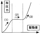
図7は、端部綴じ部25での綴じ処理時における、モータの駆動量と用紙に加わる圧力との関係を示すグラフである。図7中の区間(1)、区間(2)、区間(3)のそれぞれが、図3(b)、図3(c)、図3(d)の各状態でのモータ駆動量と用紙に加わる圧力との関係を示している。
FIG. 7 is a graph showing the relationship between the driving amount of the motor and the pressure applied to the paper during the binding process in the
図8は用紙綴じ装置6の制御に係るブロック図である。用紙綴じ装置6に設けられた制御部66は、綴じ制御手段62によって、綴じDCモータ60を動作させるための綴じ駆動部61を制御して綴じDCモータ60の動作を指示する。
FIG. 8 is a block diagram relating to the control of the
綴じ制御手段62による綴じ駆動部61の制御は、まず綴じDCモータ60の変動を検出する綴じモータ変動検出手段63で検出した変動から、加圧力変動検出手段64により目標加圧力との比較結果を加圧力変動として算出する。そして、その算出結果をもとに異常判定手段65で加圧力が正常であるかを判定して、判定した結果に応じて綴じ制御手段62で綴じDCモータ60の制御を行う。なお、モータ変動検出としては、綴じDCモータ60の電流値変動や速度変動などが挙げられる。
Control of the
モータ変動検出の例として、綴じDCモータ60の速度変動で行う場合について、図9(a)、図9(b)、図9(c)、図9(d)を用いて説明する。 As an example of motor fluctuation detection, a case where the speed fluctuation of the binding DC motor 60 is performed will be described with reference to FIGS. 9A, 9B, 9C, and 9D.
図9(a)、図9(b)、図9(c)は、綴じDCモータ60の定速駆動に関する波形である。図9(a)は綴じDCモータ60を駆動させる目標速度であり、図9(b)は高い加圧力時に綴じDCモータ60を動かした場合の実動作波形であり、図9(c)は低い加圧力時に綴じDCモータ60を動かした場合の実動作波形の一例である。 FIGS. 9A, 9 </ b> B, and 9 </ b> C are waveforms relating to constant speed driving of the binding DC motor 60. FIG. 9A shows a target speed for driving the binding DC motor 60, FIG. 9B shows an actual operation waveform when the binding DC motor 60 is moved at a high pressure, and FIG. 9C is low. It is an example of an actual operation | movement waveform at the time of moving the binding DC motor 60 at the time of pressurization.
図9(a)と、図9(b)または図9(c)とを比較すると、実動作の速度は目標速度に対してバラツキが見て取れる。 When FIG. 9 (a) is compared with FIG. 9 (b) or FIG. 9 (c), it can be seen that the actual operation speed varies with respect to the target speed.
次に、図9(b)と図9(c)とを比較すると、図9(b)に示す加圧力が高い場合の実動作波形の方が、図9(c)に示す加圧力が低い場合の実動作波形よりも、目標速度に対して大きな差異が発生する回数が多いことが分かる。 Next, when FIG. 9B is compared with FIG. 9C, the actual operating waveform when the applied pressure shown in FIG. 9B is higher is lower in the applied pressure shown in FIG. 9C. It can be seen that the number of occurrences of a large difference with respect to the target speed is larger than the actual operation waveform.
ここで、「目標速度に対する大きな差異」とは、図9(d)で示す点線の範囲外まで速度が変動したことであり、高い加圧力の場合は速度変動回数が多く、低い加圧力の場合は速度変動回数が少なくなる(図9(d)では速度変動回数が5回となる)。そのため、本実施形態では、この特性を利用して用紙綴じ装置6による用紙束綴じ処理時の加圧力の判定を行う。
Here, “a large difference with respect to the target speed” means that the speed fluctuates outside the range of the dotted line shown in FIG. 9D. When the pressure is high, the number of speed fluctuations is large, and when the pressure is low. The number of speed fluctuations decreases (the number of speed fluctuations is 5 in FIG. 9D). For this reason, in the present embodiment, the pressure applied during the sheet bundle binding process by the
ここで、従来の圧着綴じ方式の用紙綴じ装置では、用紙束の位置や用紙の仕様などにより、正常な綴じ動作が行えず、用紙束が破れたり傷が付いたり、汚れたり、シワが発生して、用紙を無駄にしたり、用紙束を除去する手間が増えるという問題があった。 Here, in the conventional binding and binding paper binding device, the normal binding operation cannot be performed depending on the position of the paper bundle or the paper specifications, and the paper bundle is torn, scratched, dirty, or wrinkled. As a result, there is a problem that paper is wasted and time and effort for removing a bundle of paper are increased.
図10は、正常な綴じ動作が行えない場合の用紙束の状態の一例を示しており、用紙束位置による綴じ不良について説明する。 FIG. 10 shows an example of the state of the sheet bundle when the normal binding operation cannot be performed, and the binding failure due to the sheet bundle position will be described.
図10に示すように用紙束の位置が綴じ範囲(圧着歯が用紙束と当接する範囲)からズレており、この状態では用紙束に対して綴じ処理を施すことができない。そのため、用紙束の用紙がバラバラなままで次処理(搬送や排出)が行われ、用紙同士が邪魔をし合い、搬送路上での引っ掛かりなどが原因で、用紙端部が折れ曲がる耳折れなどの現象が発生する虞がある。また、搬送されない用紙が残紙として判断され、処理が停止することで、使用者に装置内から用紙の除去処理を負担させることになる。 As shown in FIG. 10, the position of the sheet bundle is deviated from the binding range (the range where the crimping teeth are in contact with the sheet bundle). In this state, the binding process cannot be performed on the sheet bundle. For this reason, the next processing (conveying and discharging) is performed while the sheets in the sheet bundle are separated, causing the paper to get in the way and be caught on the conveyance path, etc. May occur. In addition, a sheet that is not transported is determined as a remaining sheet, and the process is stopped, so that the user is burdened with a process for removing the sheet from the apparatus.
次に、用紙の仕様による綴じ不良について説明する。画像形成システムでは、用紙の厚みや用紙束の枚数を使用者が指定し、指定された処理が可能であるかを判断している。しかし、指定用紙とは異なる用紙が画像形成装置の給紙トレイにセットされている場合などがあり、処理を実施しようとしても、正常な綴じ処理が行えない場合がある。無理に綴じ処理を実施すると、用紙綴じ装置の圧着歯が必要以上に強く押し付けられることで、用紙に破れやシワなどが発生する。また、綴じ処理が完了せず、綴じ処理が停止となり、使用者に装置内から用紙の除去処理を負担させることになる。 Next, a binding failure due to paper specifications will be described. In the image forming system, the user designates the thickness of the paper and the number of paper bundles, and determines whether the designated processing is possible. However, there is a case where a sheet different from the designated sheet is set in the sheet feed tray of the image forming apparatus, and normal binding processing may not be performed even if the processing is attempted. When the binding process is forcibly performed, the crimping teeth of the sheet binding device are pressed more strongly than necessary, and the sheet is torn or wrinkled. Further, the binding process is not completed, the binding process is stopped, and the user is burdened with the sheet removal process from within the apparatus.
そのため、本実施形態では、異常な綴じ動作が継続して行われるのを抑制できるように用紙綴じ装置6を構成している。
For this reason, in the present embodiment, the
図1に用紙綴じ装置6による用紙束綴じ処理の異常を判定するフローの一例を示す。なお、本フローは、図7が示す特性がみられる綴じ動作や、図3(b)、図3(c)、図3(d)の動作で説明している。
FIG. 1 shows an example of a flow for determining an abnormality in sheet bundle binding processing by the
まず、用紙後処理装置3での綴じ処理が設定される(S1)。次に、端部綴じ部25に画像形成済みの用紙が搬送されてくる(S2)。端部綴じ部25に用紙が到達したら、用紙綴じ装置6の綴じDCモータ60を駆動させ用紙綴じ装置6による用紙束の綴じ処理を開始する(S3)。そして、綴じDCモータ60の変動計測を開始する(S4)。
First, binding processing in the
なお、変動結果として、一時結果をN、最新の結果をn1、ひとつ前の結果をn2とする。 As the fluctuation result, the temporary result is N, the latest result is n1, and the previous result is n2.
綴じDCモータ60の変動を随時監視し(S5)、綴じDCモータ60に変動があれば(S5でYES)、変動結果をNとして、ひとつ前の結果を反映(n2=n1)し(S6)、一時結果を最新結果に反映(n1=N)する(S7)。そして、駆動開始から一定距離を駆動したかを判定する(S8)。なお、綴じDCモータ60の変動を随時監視し(S5)、綴じDCモータ60に変動がない場合にも(S5でNO)、駆動開始から一定距離を駆動したかを判定する(S8)。駆動開始から一定距離を駆動していれば(S8でYES)、綴じDCモータ60の変動計測を終了する(S9)。一方、駆動開始から一定距離を駆動していなければ(S8でNO)、綴じDCモータ60の変動計測を継続して行う。 The fluctuation of the binding DC motor 60 is monitored as needed (S5), and if there is a fluctuation in the binding DC motor 60 (YES in S5), the fluctuation result is set as N and the previous result is reflected (n2 = n1) (S6). The temporary result is reflected in the latest result (n1 = N) (S7). Then, it is determined whether a certain distance has been driven from the start of driving (S8). Note that the fluctuation of the binding DC motor 60 is monitored as needed (S5), and even when there is no fluctuation in the binding DC motor 60 (NO in S5), it is determined whether a certain distance has been driven from the start of driving (S8). If driving a certain distance from the start of driving (YES in S8), the variation measurement of the binding DC motor 60 is terminated (S9). On the other hand, if the fixed distance has not been driven since the start of driving (NO in S8), the fluctuation measurement of the binding DC motor 60 is continuously performed.
綴じDCモータ60の変動計測を終了した後、n1とn2とを比較して、加圧力に異常があるかを判定する(S10)。異常無しと判定された場合には(S10でYES)、綴じ処理を継続して行う。一方、異常有りと判定された場合には(S10でNO)、後述する異常処理の制御を実行する。 After measuring the fluctuation of the binding DC motor 60, n1 and n2 are compared to determine whether there is an abnormality in the applied pressure (S10). If it is determined that there is no abnormality (YES in S10), the binding process is continued. On the other hand, when it is determined that there is an abnormality (NO in S10), control of an abnormality process described later is executed.
<異常処理>
まず、綴じDCモータ60を停止する(S1’)。次に、綴じDCモータ60を初期位置まで移動させ、用紙束を解放する(S2’)。そして、解放された用紙束に排出処理を実施する(S3’)。
<Abnormal processing>
First, the binding DC motor 60 is stopped (S1 ′). Next, the binding DC motor 60 is moved to the initial position to release the sheet bundle (S2 ′). Then, discharge processing is performed on the released sheet bundle (S3 ′).
このように、異常有りと判定された場合には、無理やり綴じ処理を続行しないので、用紙への大きなダメージが発生しない。また、異常時にも用紙束が排出されるため、ユーザーが装置内から用紙束を除去処理する手間を省くことができる。 As described above, when it is determined that there is an abnormality, the binding process is not forcibly continued, so that the paper is not significantly damaged. Further, since the sheet bundle is discharged even in an abnormal state, it is possible to save the user from having to remove the sheet bundle from the apparatus.
図11に用紙綴じ装置6による用紙束綴じ処理の異常を判定するフローの他例を示す。
図7の区間(1)では、圧着歯が用紙束に接触して、徐々に用紙を押し込んでいく状態である。動作としては、図3(b)に示すように圧着歯が用紙に接触し、用紙表面に力が加わった状態ある。この際、異常を判定する制御のフローは、図11に示すフローチャートに従い、以下のようになる。
FIG. 11 shows another example of a flow for determining an abnormality in the sheet bundle binding process by the
In the section (1) in FIG. 7, the crimping teeth are in contact with the sheet bundle and the sheet is gradually pushed in. As an operation, as shown in FIG. 3B, the crimping teeth are in contact with the paper and a force is applied to the paper surface. At this time, the control flow for determining abnormality is as follows according to the flowchart shown in FIG.
まず、用紙後処理装置3での綴じ処理が設定される(S1)。次に、端部綴じ部25に画像形成済みの用紙が搬送されてくる(S2)。端部綴じ部25に用紙が到達したら、用紙束を整合手段で整合する(S3)。用紙束の整合が終わったら、用紙綴じ装置6の綴じDCモータ60を駆動させ用紙綴じ装置6による用紙束の綴じ処理を開始する(S4)。そして、綴じDCモータ60の変動計測を開始する(S5)。
First, binding processing in the
なお、変動結果として、一時結果をN、最新の結果をn1、ひとつ前の結果をn2とする。 As the fluctuation result, the temporary result is N, the latest result is n1, and the previous result is n2.
綴じDCモータ60の変動を随時監視し(S6)、綴じDCモータ60に変動があれば(S6でYES)、変動結果をNとして、ひとつ前の結果を反映(n2=n1)し(S7)、一時結果を最新結果に反映(n1=N)する(S8)。そして、駆動開始から一定距離を駆動したかを判定する(S9)。なお、綴じDCモータ60の変動を随時監視し(S6)、綴じDCモータ60に変動がない場合にも(S6でNO)、駆動開始から一定距離を駆動したかを判定する(S9)。駆動開始から一定距離を駆動していれば(S9でYES)、綴じDCモータ60の変動計測を終了する(S10)。一方、駆動開始から一定距離を駆動していなければ(S9でNO)、綴じDCモータ60の変動計測を継続して行う。 The fluctuation of the binding DC motor 60 is monitored as needed (S6), and if there is a fluctuation in the binding DC motor 60 (YES in S6), the fluctuation result is set as N and the previous result is reflected (n2 = n1) (S7). The temporary result is reflected in the latest result (n1 = N) (S8). Then, it is determined whether a certain distance has been driven from the start of driving (S9). Note that the fluctuation of the binding DC motor 60 is monitored as needed (S6), and even when there is no fluctuation in the binding DC motor 60 (NO in S6), it is determined whether or not a fixed distance has been driven (S9). If driving a certain distance from the start of driving (YES in S9), the variation measurement of the binding DC motor 60 is terminated (S10). On the other hand, if the fixed distance is not driven from the start of driving (NO in S9), the fluctuation measurement of the binding DC motor 60 is continuously performed.
綴じDCモータ60の変動計測を終了した後、n1とn2とを比較して、加圧力に異常があるかを判定する(S11)。n1>n2の場合には異常無しと判定し(S11でYES)、綴じ処理を継続して行う。一方、n1>n2ではない場合、すなわち、n1≦n2の場合には異常有りと判定し(S11でNO)、異常処理中であるかどうかを判定する(S12)。異常処理中である場合には(S12でYES)、処理状態フラグをEX=0として(S13)、後述する異常処理の制御を実行する。一方、異常処理中でない場合には(S12でNO)、処理状態フラグをEX=1として(S14)、後述する異常処理の制御を実行する。 After measuring the fluctuation of the binding DC motor 60, n1 and n2 are compared to determine whether there is an abnormality in the applied pressure (S11). If n1> n2, it is determined that there is no abnormality (YES in S11), and the binding process is continued. On the other hand, if n1> n2 is not satisfied, that is, if n1 ≦ n2, it is determined that there is an abnormality (NO in S11), and it is determined whether abnormality processing is being performed (S12). If abnormal processing is in progress (YES in S12), the processing status flag is set to EX = 0 (S13), and control of abnormal processing described later is executed. On the other hand, when the abnormal process is not in progress (NO in S12), the process state flag is set to EX = 1 (S14), and the control of the abnormal process described later is executed.
<異常処理>
まじ、綴じDCモータ60を停止する(S1’)。次に、綴じDCモータ60を初期位置まで移動させ、用紙束を解放する(S2’)。そして、処理フラグを判定し(S3’)、EX=0の場合には(S3’でYES)、解放された用紙束に排出処理を実施する(S4’)。一方、処理フラグを判定し(S3’)、EX=0でない場合、すなわち、EX=1の場合には(S3’でNO)、通常の綴じ処理の制御フローに戻って用紙束の整合を行い(S3)、一連の制御を繰り返し行う。
<Abnormal processing>
Seriously, the binding DC motor 60 is stopped (S1 ′). Next, the binding DC motor 60 is moved to the initial position to release the sheet bundle (S2 ′). Then, the processing flag is determined (S3 ′). When EX = 0 (YES in S3 ′), the discharged sheet bundle is discharged (S4 ′). On the other hand, if the processing flag is determined (S3 ′) and EX = 0 is not satisfied, that is, if EX = 1 (NO in S3 ′), the process returns to the normal binding processing control flow to perform sheet bundle alignment. (S3) A series of control is repeated.
これにより、圧着歯に対して確実に用紙束が整合されるため、綴じ位置がズレたり、用紙1枚だけに綴じ処理されるような綴じ不良の発生を抑制することができる。 Thereby, since the sheet bundle is reliably aligned with the crimping tooth, it is possible to suppress the occurrence of a binding failure in which the binding position is shifted or the binding process is performed on only one sheet.
図12に用紙綴じ装置6による用紙束綴じ処理の異常を判定するフローの他例を示す。
図7の区間(1)と区間(2)とでは、用紙束が圧着歯の形状に合わせて、徐々に変形していく状態である。動作としては、図3(b)に示す状態から始まり図3(c)に示すように用紙が圧着歯の形状に沿うように変形する前までである。この際、異常を判定する制御のフローは、図12に示すフローチャートに従い、以下のようになる。
FIG. 12 shows another example of a flow for determining an abnormality in the sheet bundle binding process by the
In section (1) and section (2) in FIG. 7, the sheet bundle is gradually deformed in accordance with the shape of the pressure-bonding teeth. The operation starts from the state shown in FIG. 3B and before the sheet is deformed so as to conform to the shape of the crimp tooth as shown in FIG. 3C. At this time, the flow of control for determining abnormality is as follows according to the flowchart shown in FIG.
まず、用紙後処理装置3での綴じ処理が設定される(S1)。次に、端部綴じ部25に画像形成済みの用紙が搬送されてくる(S2)。端部綴じ部25に用紙が到達したら、用紙束を整合手段で整合する(S3)。用紙束の整合が終わったら、用紙綴じ装置6の綴じDCモータ60を駆動させ用紙綴じ装置6による用紙束の綴じ処理を開始する(S4)。そして、綴じDCモータ60の変動計測を開始する(S5)。
First, binding processing in the
なお、変動結果として、一時結果をN、最新の結果をn1、ひとつ前の結果をn2とする。 As the fluctuation result, the temporary result is N, the latest result is n1, and the previous result is n2.
綴じDCモータ60の変動を随時監視し(S6)、綴じDCモータ60に変動があれば(S6でYES)、変動結果をNとして、ひとつ前の結果を反映(n2=n1)し(S7)、一時結果を最新結果に反映(n1=N)する(S8)。そして、駆動開始から一定距離を駆動したかを判定する(S9)。なお、綴じDCモータ60の変動を随時監視し(S6)、綴じDCモータ60に変動がない場合にも(S6でNO)、駆動開始から一定距離を駆動したかを判定する(S9)。駆動開始から一定距離を駆動していれば(S9でYES)、綴じDCモータ60の変動計測を終了する(S10)。一方、駆動開始から一定距離を駆動していなければ(S9でNO)、綴じDCモータ60の変動計測を継続して行う。 The fluctuation of the binding DC motor 60 is monitored as needed (S6), and if there is a fluctuation in the binding DC motor 60 (YES in S6), the fluctuation result is set as N and the previous result is reflected (n2 = n1) (S7). The temporary result is reflected in the latest result (n1 = N) (S8). Then, it is determined whether a certain distance has been driven from the start of driving (S9). Note that the fluctuation of the binding DC motor 60 is monitored as needed (S6), and even when there is no fluctuation in the binding DC motor 60 (NO in S6), it is determined whether or not a fixed distance has been driven (S9). If driving a certain distance from the start of driving (YES in S9), the variation measurement of the binding DC motor 60 is terminated (S10). On the other hand, if the fixed distance is not driven from the start of driving (NO in S9), the fluctuation measurement of the binding DC motor 60 is continuously performed.
綴じDCモータ60の変動計測を終了した後、n1とn2とを比較して、加圧力に異常があるかを判定する(S11)。n1<n2の場合には異常無しと判定し(S11でYES)、綴じ処理を継続して行う。一方、n1<n2でない場合、すなわち、n1≧n2の場合には異常有りと判定し(S11でNO)、後述する異常処理の制御を実行する。 After measuring the fluctuation of the binding DC motor 60, n1 and n2 are compared to determine whether there is an abnormality in the applied pressure (S11). If n1 <n2, it is determined that there is no abnormality (YES in S11), and the binding process is continued. On the other hand, if n1 <n2, that is, if n1 ≧ n2, it is determined that there is an abnormality (NO in S11), and control of an abnormality process described later is executed.
<異常処理>
まず、綴じDCモータ60を停止する(S1’)。次に、綴じDCモータ60を初期位置まで移動させ、用紙束を解放する(S2’)。そして、解放された用紙束に排出処理を実施する(S3’)。
<Abnormal processing>
First, the binding DC motor 60 is stopped (S1 ′). Next, the binding DC motor 60 is moved to the initial position to release the sheet bundle (S2 ′). Then, discharge processing is performed on the released sheet bundle (S3 ′).
これにより、無理やり綴じ処理を続行しないため、圧着歯による用紙表面での破れが発生するのを抑制することができる。また、異常時にも用紙束が排出されるため、ユーザーが装置内から用紙束を除去処理する手間を省くことができる。 Accordingly, the binding process is not continued forcibly, so that it is possible to suppress the tearing of the paper surface due to the crimping teeth. Further, since the sheet bundle is discharged even in an abnormal state, it is possible to save the user from having to remove the sheet bundle from the apparatus.
図13に用紙綴じ装置6による用紙束綴じ処理の異常を判定するフローの他例を示す。
図7の区間(2)と区間(3)とでは、用紙束が圧着歯の形状に合わせて、押しつぶされていく状態である。動作としては、図3(c)の状態から始まり図3(d)のように用紙が圧着歯の形状に沿うように変形する前までである。この際、異常を判定する制御のフローは、図13に示すフローチャートに従い、以下のようになる。
FIG. 13 shows another example of a flow for determining an abnormality in the sheet bundle binding process by the
In the section (2) and the section (3) in FIG. 7, the sheet bundle is crushed in accordance with the shape of the crimp tooth. The operation starts from the state shown in FIG. 3C and before the sheet is deformed so as to follow the shape of the pressure-bonding teeth as shown in FIG. 3D. At this time, the control flow for determining abnormality is as follows according to the flowchart shown in FIG.
まず、用紙後処理装置3での綴じ処理が設定される(S1)。次に、端部綴じ部25に画像形成済みの用紙が搬送されてくる(S2)。端部綴じ部25に用紙が到達したら、用紙束を整合手段で整合する(S3)。用紙束の整合が終わったら、用紙綴じ装置6の綴じDCモータ60を駆動させ、用紙綴じ装置6による用紙束の綴じ処理を開始する(S4)。そして、綴じDCモータ60の変動計測を開始する(S5)。
First, binding processing in the
なお、変動結果として、一時結果をN、最新の結果をn1、ひとつ前の結果をn2とする。 As the fluctuation result, the temporary result is N, the latest result is n1, and the previous result is n2.
綴じDCモータ60の変動を随時監視し(S6)、綴じDCモータ60に変動があれば(S6でYES)、変動結果をNとして、ひとつ前の結果を反映(n2=n1)し(S7)、一時結果を最新結果に反映(n1=N)する(S8)。そして、駆動開始から一定距離を駆動したかを判定する(S9)。なお、綴じDCモータ60の変動を随時監視し(S6)、綴じDCモータ60に変動がない場合にも(S6でNO)、駆動開始から一定距離を駆動したかを判定する(S9)。駆動開始から一定距離を駆動していれば(S9でYES)、綴じDCモータ60の変動計測を終了する(S10)。一方、駆動開始から一定距離を駆動していなければ(S9でNO)、綴じDCモータ60の変動計測を継続して行う。 The fluctuation of the binding DC motor 60 is monitored as needed (S6), and if there is a fluctuation in the binding DC motor 60 (YES in S6), the fluctuation result is set as N and the previous result is reflected (n2 = n1) (S7). The temporary result is reflected in the latest result (n1 = N) (S8). Then, it is determined whether a certain distance has been driven from the start of driving (S9). Note that the fluctuation of the binding DC motor 60 is monitored as needed (S6), and even when there is no fluctuation in the binding DC motor 60 (NO in S6), it is determined whether or not a fixed distance has been driven (S9). If driving a certain distance from the start of driving (YES in S9), the variation measurement of the binding DC motor 60 is terminated (S10). On the other hand, if the fixed distance is not driven from the start of driving (NO in S9), the fluctuation measurement of the binding DC motor 60 is continuously performed.
綴じDCモータ60の変動計測を終了した後、n1とn2とを比較して、加圧力に異常があるかを判定する(S11)。n1>n2の場合には異常無しと判定し(S11でYES)、綴じ処理を継続して行う。一方、n1>n2でない場合、すなわち、n1≦n2の場合には異常有りと判定し(S11でNO)、後述する異常処理の制御を実行する。 After measuring the fluctuation of the binding DC motor 60, n1 and n2 are compared to determine whether there is an abnormality in the applied pressure (S11). If n1> n2, it is determined that there is no abnormality (YES in S11), and the binding process is continued. On the other hand, if n1> n2 is not satisfied, that is, if n1 ≦ n2, it is determined that there is an abnormality (NO in S11), and control of an abnormality process described later is executed.
<異常処理>
まず、綴じDCモータ60を停止する(S1’)。次に、綴じDCモータ60を初期位置まで移動させ、用紙束を解放する(S2’)。そして、解放された用紙束に排出処理を実施する(S3’)。
<Abnormal processing>
First, the binding DC motor 60 is stopped (S1 ′). Next, the binding DC motor 60 is moved to the initial position to release the sheet bundle (S2 ′). Then, discharge processing is performed on the released sheet bundle (S3 ′).
これにより、無理やり綴じ処理を続行しないため、圧着歯による用紙束のシワや破れが発生するのを抑制することができる。また、異常時にも用紙束が排出されるため、ユーザーが装置内から用紙束を除去処理する手間を省くことができる。 As a result, the binding process is not forcibly continued, so that it is possible to prevent the sheet bundle from being wrinkled or torn due to the crimping teeth. Further, since the sheet bundle is discharged even in an abnormal state, it is possible to save the user from having to remove the sheet bundle from the apparatus.
以上に説明したものは一例であり、本発明は、次の態様毎に特有の効果を奏する。
(態様A)
用紙を積載する用紙積載トレイ23などの用紙積載手段と、凹凸形状を有する一対の上圧着歯101及び下圧着歯102などの圧着部材を有する綴じ手段とを備え、前記用紙積載手段に積載された用紙束を前記綴じ手段によって綴じる圧着綴じ方式の用紙綴じ装置6などの用紙綴じ装置において、前記綴じ手段による前記用紙束の綴じ動作時に用紙束に加わる圧力を検知する綴じモータ変動検出手段63や加圧力変動検出手段64などの圧力検知手段と、前記圧力検知手段の検知結果に基づいて前記用紙束に所定の圧力が加えられているかを判定する異常判定手段65などの判定手段と、前記判定手段の判定結果に応じて前記用紙束に所定の圧力が加えられていない場合に、前記綴じ手段による綴じ動作を停止させる制御を行う綴じ制御手段などの制御手段とを有する。これよれば、上記実施形態について説明したように、異常な綴じ動作が継続して行われるのを抑制することができる。
(態様B)
(態様A)において、上記用紙積載手段に積載された用紙を整合する第1のジョガーフェンス24などの用紙整合手段とを有しており、上記判定手段によって上記用紙束に所定の圧力が加わっていないと判定した場合には、上記制御手段によって上記綴じ手段による綴じ動作を停止させ、前記用紙整合手段による整合動作を実施後、綴じ手段による綴じ動作を再開する。これによれば、上記実施形態について説明したように、整合不良のままで用紙束を綴じないので、用紙端部などが折れるなどの綴じ不良の発生を抑えることができる。
(態様C)
(態様A)または(態様B)において、上記用紙積載手段に積載された用紙を排出する排出手段を有しており、上記判定手段によって上記用紙束への圧力が一定時間経過後も所定の圧力より上昇し続けていると判定した場合には、上記制御手段によって上記綴じ手段による綴じ動作を停止させ、前記用紙積載手段に積載された用紙束を前記排出手段により排出する。これによれば、上記実施形態について説明したように、種類の異なる用紙の混載や設定ミスなどで用紙綴じ装置の仕様を超えていても、圧着歯によって用紙に破れが発生するのを抑制することができる。
(態様D)
(態様A)、(態様B)または(態様C)において、上記判定手段によって上記用紙束への圧力が一定時間変動していないと判定した場合には、上記制御手段によって上記綴じ手段による綴じ動作を停止させ、上記用紙積載手段に積載された前記用紙束を上記排出手段により排出する。これによれば、上記実施形態について説明したように、種類の異なる用紙の混載や設定ミスなどで用紙綴じ装置の仕様を超えていても、圧着歯によって用紙に破れが発生するのを抑制することができる。
(態様E)
用紙束に対して綴じ処理を施す用紙綴じ装置を少なくとも備えた用紙後処理装置3などの用紙処理装置において、前記用紙綴じ装置として、(態様A)、(態様B)、(態様C)または(態様D)の用紙綴じ装置を用いた。これによれば、上記実施形態について説明したように、異常な綴じ動作が継続して行われるのを抑制し、良好な綴じ処理を行うことができる。
(態様F)
用紙上に画像を形成する画像形成装置2などの画像形成装置と、前記画像形成装置によって画像が形成された用紙の束に綴じ処理を施す用紙綴じ装置を少なくとも備えた用紙後処理装置3などの用紙処理装置とを備えた画像形成システム1などの画像形成システムにおいて、前記用紙処理装置として、(態様E)の用紙処理装置を用いた。これによれば、上記実施形態について説明したように、異常な綴じ動作が継続して行われるのを抑制し、画像が形成された用紙の束に対して良好な綴じ処理を行うことができる。
What has been described above is merely an example, and the present invention has a specific effect for each of the following modes.
(Aspect A)
A sheet stacking unit such as a
(Aspect B)
(Aspect A) includes sheet aligning means such as a
(Aspect C)
In (Aspect A) or (Aspect B), a discharge unit that discharges the paper stacked on the paper stacking unit is provided, and the determination unit applies a predetermined pressure even after a predetermined time has passed. When it is determined that the sheet continues to rise, the control unit stops the binding operation by the binding unit, and the stack of sheets stacked on the sheet stacking unit is discharged by the discharge unit. According to this, as described in the above embodiment, even if the specifications of the paper binding device exceed the specifications of the paper binding apparatus due to mixed loading of different types of paper or setting mistakes, it is possible to suppress tearing of the paper due to the crimping teeth. Can do.
(Aspect D)
In (Aspect A), (Aspect B), or (Aspect C), when the determination unit determines that the pressure on the sheet bundle has not fluctuated for a certain period of time, the control unit performs the binding operation by the binding unit. Is stopped, and the sheet bundle loaded on the sheet stacking means is discharged by the discharging means. According to this, as described in the above embodiment, even if the specifications of the paper binding device exceed the specifications of the paper binding apparatus due to mixed loading of different types of paper or setting mistakes, it is possible to suppress tearing of the paper due to the crimping teeth. Can do.
(Aspect E)
In a sheet processing apparatus such as the sheet
(Aspect F)
An image forming apparatus such as an
1 画像形成システム
2 画像形成装置
3 用紙後処理装置
6 用紙綴じ装置
10 排紙トレイ
11 入口ローラ
12 搬送ローラ
13 搬送ローラ
14 排紙ローラ
15 入口センサ
17 分岐爪
20 搬送ローラ
21 搬送ローラ
22 搬送ローラ
23 用紙積載トレイ
24 ジョガーフェンス
25 端部綴じ部
26 分岐爪
27 分岐爪
28 束化部
31 搬送ローラ
32 搬送ローラ
33 中綴じ折り部
34 中折り部
35 中綴じ部
36 束化部
37 可動基準フェンス
38 ブレード
39 押圧ローラ
40 押圧ローラ
41 排紙ローラ
42 排紙トレイ
51 搬送部
52 経路切り替え部
60 綴じDCモータ
61 綴じ駆動部
62 綴じ制御手段
63 綴じモータ変動検出手段
64 加圧力変動検出手段
65 異常判定手段
66 制御部
101 上圧着歯
102 下圧着歯
111 上歯アーム
112 下歯アーム
113 アーム回転中心部
114 ギヤ
115 カム駆動ギヤ
116 歯押しカム
117 歯戻しバネ
DESCRIPTION OF
Claims (6)
凹凸形状を有する一対の圧着部材を有する綴じ手段とを備え、
前記用紙積載手段に積載された用紙束を前記綴じ手段によって綴じる圧着綴じ方式の用紙綴じ装置において、
前記綴じ手段による前記用紙束の綴じ動作時に該用紙束に加わる圧力を検知する圧力検知手段と、
前記圧力検知手段の検知結果に基づいて前記用紙束に所定の圧力が加えられているかを判定する判定手段と、
前記判定手段の判定結果に応じて前記用紙束に所定の圧力が加えられていない場合に、前記綴じ手段による綴じ動作を停止させる制御を行う制御手段とを有することを特徴とする用紙綴じ装置。 Paper loading means for loading paper;
Binding means having a pair of crimping members having an uneven shape,
In the paper binding apparatus of the pressure binding method that binds the paper stack loaded on the paper stacking means by the binding means,
Pressure detecting means for detecting pressure applied to the sheet bundle during the binding operation of the sheet bundle by the binding means;
Determination means for determining whether a predetermined pressure is applied to the sheet bundle based on a detection result of the pressure detection means;
And a control unit configured to control to stop a binding operation by the binding unit when a predetermined pressure is not applied to the sheet bundle according to a determination result of the determination unit.
上記用紙積載手段に積載された用紙を整合する用紙整合手段とを有しており、
上記判定手段によって上記用紙束に所定の圧力が加わっていないと判定した場合には、上記制御手段によって上記綴じ手段による綴じ動作を停止させ、前記用紙整合手段による整合動作を実施後、該綴じ手段による綴じ動作を再開することを特徴とする用紙綴じ装置。 In the paper binding apparatus according to claim 1,
Paper aligning means for aligning the paper loaded on the paper stacking means,
When the determination means determines that a predetermined pressure is not applied to the sheet bundle, the control means stops the binding operation by the binding means, and after the alignment operation by the paper alignment means is performed, the binding means The sheet binding apparatus is characterized by restarting the binding operation by the printer.
上記用紙積載手段に積載された用紙を排出する排出手段を有しており、
上記判定手段によって上記用紙束への圧力が一定時間経過後も所定の圧力より上昇し続けていると判定した場合には、上記制御手段によって上記綴じ手段による綴じ動作を停止させ、前記用紙積載手段に積載された用紙束を前記排出手段により排出することを特徴とする用紙綴じ装置。 In the paper binding apparatus according to claim 1 or 2,
A discharge means for discharging the paper loaded on the paper stacking means;
If it is determined by the determination means that the pressure on the sheet bundle continues to rise above a predetermined pressure even after a predetermined time has elapsed, the control means stops the binding operation by the binding means, and the sheet stacking means A sheet binding device, wherein the sheet bundle loaded on the sheet is discharged by the discharge unit.
上記判定手段によって上記用紙束への圧力が一定時間変動していないと判定した場合には、上記制御手段によって上記綴じ手段による綴じ動作を停止させ、上記用紙積載手段に積載された前記用紙束を上記排出手段により排出することを特徴とする用紙綴じ装置。 In the paper binding apparatus according to claim 3 ,
If the determination means determines that the pressure on the sheet bundle has not fluctuated for a certain period of time, the control means stops the binding operation by the binding means, and removes the sheet bundle loaded on the sheet stacking means. A paper binding apparatus, wherein the paper is discharged by the discharge means.
前記用紙綴じ装置として、請求項1、2、3または4の用紙綴じ装置を用いたことを特徴とする用紙処理装置。 In a paper processing apparatus including at least a paper binding device that performs a binding process on a paper bundle,
5. A sheet processing apparatus using the sheet binding apparatus according to claim 1, 2, 3, or 4 as the sheet binding apparatus.
前記画像形成装置によって画像が形成された用紙の束に綴じ処理を施す用紙綴じ装置を少なくとも備えた用紙処理装置とを備えた画像形成システムにおいて、
前記用紙処理装置として、請求項5の用紙処理装置を用いたことを特徴とする画像形成システム。 An image forming apparatus for forming an image on paper;
In an image forming system comprising: a sheet processing apparatus including at least a sheet binding apparatus that performs a binding process on a bundle of sheets on which images are formed by the image forming apparatus.
An image forming system using the sheet processing apparatus according to claim 5 as the sheet processing apparatus.
Priority Applications (1)
| Application Number | Priority Date | Filing Date | Title |
|---|---|---|---|
| JP2012252316A JP6004268B2 (en) | 2012-11-16 | 2012-11-16 | Sheet binding apparatus, sheet processing apparatus, and image forming system |
Applications Claiming Priority (1)
| Application Number | Priority Date | Filing Date | Title |
|---|---|---|---|
| JP2012252316A JP6004268B2 (en) | 2012-11-16 | 2012-11-16 | Sheet binding apparatus, sheet processing apparatus, and image forming system |
Publications (2)
| Publication Number | Publication Date |
|---|---|
| JP2014101157A JP2014101157A (en) | 2014-06-05 |
| JP6004268B2 true JP6004268B2 (en) | 2016-10-05 |
Family
ID=51024045
Family Applications (1)
| Application Number | Title | Priority Date | Filing Date |
|---|---|---|---|
| JP2012252316A Active JP6004268B2 (en) | 2012-11-16 | 2012-11-16 | Sheet binding apparatus, sheet processing apparatus, and image forming system |
Country Status (1)
| Country | Link |
|---|---|
| JP (1) | JP6004268B2 (en) |
Family Cites Families (4)
| Publication number | Priority date | Publication date | Assignee | Title |
|---|---|---|---|---|
| JP3197029B2 (en) * | 1991-08-30 | 2001-08-13 | キヤノン株式会社 | Sheet feeding device |
| JP4445943B2 (en) * | 2006-05-22 | 2010-04-07 | 京セラミタ株式会社 | Image forming system and image forming method |
| JP5376985B2 (en) * | 2009-02-17 | 2013-12-25 | キヤノン株式会社 | Sheet binding apparatus and image forming apparatus |
| JP5447075B2 (en) * | 2010-03-26 | 2014-03-19 | 富士ゼロックス株式会社 | Image forming system and recording material post-processing apparatus |
-
2012
- 2012-11-16 JP JP2012252316A patent/JP6004268B2/en active Active
Also Published As
| Publication number | Publication date |
|---|---|
| JP2014101157A (en) | 2014-06-05 |
Similar Documents
| Publication | Publication Date | Title |
|---|---|---|
| JP6288543B2 (en) | Sheet processing apparatus, image forming system, and image forming apparatus | |
| JP6308418B2 (en) | Paper binding device, paper processing device, and image forming system | |
| JP6232704B2 (en) | Sheet processing apparatus and image forming system | |
| JP7064712B2 (en) | Sheet processing equipment and image forming system | |
| JP7064714B2 (en) | Sheet processing equipment and image forming system | |
| JP4143446B2 (en) | Sheet processing apparatus and image forming apparatus provided with the apparatus | |
| JP2013234068A (en) | Sheet processing device and image forming system | |
| JP2015020339A (en) | Sheet bundle binding processing apparatus and image forming system having the same | |
| JP5971032B2 (en) | Paper post-processing apparatus and image forming system | |
| US20130127106A1 (en) | Post-processing apparatus and post-processing method | |
| JP2014108871A (en) | Post-processing device, image formation apparatus including post-processing device, and image formation system including post-processing device | |
| JP2020093929A (en) | Post-processing device, image formation device and image formation system | |
| WO2017209162A1 (en) | Teeth part, binder, paper-processing apparatus, and image formation system | |
| JP4800022B2 (en) | Sheet processing apparatus and image forming apparatus | |
| JP5929237B2 (en) | Sheet processing apparatus, image forming system, and sheet stacking method | |
| JP6004268B2 (en) | Sheet binding apparatus, sheet processing apparatus, and image forming system | |
| JP4842725B2 (en) | Sheet processing apparatus and image forming apparatus | |
| JP2017071467A (en) | Sheet bundle binding process device and image formation system equipped with the same | |
| JP6558657B2 (en) | Sheet processing apparatus, image forming system, and image forming apparatus | |
| JP6737362B2 (en) | Sheet processing apparatus and image forming system | |
| JP6988968B2 (en) | Teeth, binding tools, paper processing equipment and image forming systems | |
| JP2014058383A (en) | Sheet processing device, image forming system and sheet binding method | |
| JP2014172693A (en) | Paper processing device, image formation system and paper bundle binding method | |
| JP5685977B2 (en) | Paper post-processing apparatus and image forming system | |
| JP4522149B2 (en) | Paper processing device |
Legal Events
| Date | Code | Title | Description |
|---|---|---|---|
| A621 | Written request for application examination |
Free format text: JAPANESE INTERMEDIATE CODE: A621 Effective date: 20151015 |
|
| A131 | Notification of reasons for refusal |
Free format text: JAPANESE INTERMEDIATE CODE: A131 Effective date: 20160610 |
|
| A521 | Written amendment |
Free format text: JAPANESE INTERMEDIATE CODE: A523 Effective date: 20160706 |
|
| TRDD | Decision of grant or rejection written | ||
| A01 | Written decision to grant a patent or to grant a registration (utility model) |
Free format text: JAPANESE INTERMEDIATE CODE: A01 Effective date: 20160812 |
|
| A61 | First payment of annual fees (during grant procedure) |
Free format text: JAPANESE INTERMEDIATE CODE: A61 Effective date: 20160825 |
|
| R151 | Written notification of patent or utility model registration |
Ref document number: 6004268 Country of ref document: JP Free format text: JAPANESE INTERMEDIATE CODE: R151 |