JP6760963B2 - Angled torque transmission system and method - Google Patents
Angled torque transmission system and method Download PDFInfo
- Publication number
- JP6760963B2 JP6760963B2 JP2017557037A JP2017557037A JP6760963B2 JP 6760963 B2 JP6760963 B2 JP 6760963B2 JP 2017557037 A JP2017557037 A JP 2017557037A JP 2017557037 A JP2017557037 A JP 2017557037A JP 6760963 B2 JP6760963 B2 JP 6760963B2
- Authority
- JP
- Japan
- Prior art keywords
- torque
- clutch device
- pulley
- output
- clutch
- Prior art date
- Legal status (The legal status is an assumption and is not a legal conclusion. Google has not performed a legal analysis and makes no representation as to the accuracy of the status listed.)
- Active
Links
Images


Classifications
-
- B—PERFORMING OPERATIONS; TRANSPORTING
- B60—VEHICLES IN GENERAL
- B60K—ARRANGEMENT OR MOUNTING OF PROPULSION UNITS OR OF TRANSMISSIONS IN VEHICLES; ARRANGEMENT OR MOUNTING OF PLURAL DIVERSE PRIME-MOVERS IN VEHICLES; AUXILIARY DRIVES FOR VEHICLES; INSTRUMENTATION OR DASHBOARDS FOR VEHICLES; ARRANGEMENTS IN CONNECTION WITH COOLING, AIR INTAKE, GAS EXHAUST OR FUEL SUPPLY OF PROPULSION UNITS IN VEHICLES
- B60K11/00—Arrangement in connection with cooling of propulsion units
- B60K11/06—Arrangement in connection with cooling of propulsion units with air cooling
-
- F—MECHANICAL ENGINEERING; LIGHTING; HEATING; WEAPONS; BLASTING
- F02—COMBUSTION ENGINES; HOT-GAS OR COMBUSTION-PRODUCT ENGINE PLANTS
- F02B—INTERNAL-COMBUSTION PISTON ENGINES; COMBUSTION ENGINES IN GENERAL
- F02B67/00—Engines characterised by the arrangement of auxiliary apparatus not being otherwise provided for, e.g. the apparatus having different functions; Driving auxiliary apparatus from engines, not otherwise provided for
- F02B67/04—Engines characterised by the arrangement of auxiliary apparatus not being otherwise provided for, e.g. the apparatus having different functions; Driving auxiliary apparatus from engines, not otherwise provided for of mechanically-driven auxiliary apparatus
- F02B67/06—Engines characterised by the arrangement of auxiliary apparatus not being otherwise provided for, e.g. the apparatus having different functions; Driving auxiliary apparatus from engines, not otherwise provided for of mechanically-driven auxiliary apparatus driven by means of chains, belts, or like endless members
-
- B—PERFORMING OPERATIONS; TRANSPORTING
- B60—VEHICLES IN GENERAL
- B60K—ARRANGEMENT OR MOUNTING OF PROPULSION UNITS OR OF TRANSMISSIONS IN VEHICLES; ARRANGEMENT OR MOUNTING OF PLURAL DIVERSE PRIME-MOVERS IN VEHICLES; AUXILIARY DRIVES FOR VEHICLES; INSTRUMENTATION OR DASHBOARDS FOR VEHICLES; ARRANGEMENTS IN CONNECTION WITH COOLING, AIR INTAKE, GAS EXHAUST OR FUEL SUPPLY OF PROPULSION UNITS IN VEHICLES
- B60K25/00—Auxiliary drives
- B60K25/02—Auxiliary drives directly from an engine shaft
-
- F—MECHANICAL ENGINEERING; LIGHTING; HEATING; WEAPONS; BLASTING
- F01—MACHINES OR ENGINES IN GENERAL; ENGINE PLANTS IN GENERAL; STEAM ENGINES
- F01P—COOLING OF MACHINES OR ENGINES IN GENERAL; COOLING OF INTERNAL-COMBUSTION ENGINES
- F01P7/00—Controlling of coolant flow
- F01P7/02—Controlling of coolant flow the coolant being cooling-air
- F01P7/04—Controlling of coolant flow the coolant being cooling-air by varying pump speed, e.g. by changing pump-drive gear ratio
- F01P7/042—Controlling of coolant flow the coolant being cooling-air by varying pump speed, e.g. by changing pump-drive gear ratio using fluid couplings
-
- F—MECHANICAL ENGINEERING; LIGHTING; HEATING; WEAPONS; BLASTING
- F01—MACHINES OR ENGINES IN GENERAL; ENGINE PLANTS IN GENERAL; STEAM ENGINES
- F01P—COOLING OF MACHINES OR ENGINES IN GENERAL; COOLING OF INTERNAL-COMBUSTION ENGINES
- F01P7/00—Controlling of coolant flow
- F01P7/02—Controlling of coolant flow the coolant being cooling-air
- F01P7/08—Controlling of coolant flow the coolant being cooling-air by cutting in or out of pumps
- F01P7/081—Controlling of coolant flow the coolant being cooling-air by cutting in or out of pumps using clutches, e.g. electro-magnetic or induction clutches
-
- F—MECHANICAL ENGINEERING; LIGHTING; HEATING; WEAPONS; BLASTING
- F16—ENGINEERING ELEMENTS AND UNITS; GENERAL MEASURES FOR PRODUCING AND MAINTAINING EFFECTIVE FUNCTIONING OF MACHINES OR INSTALLATIONS; THERMAL INSULATION IN GENERAL
- F16H—GEARING
- F16H55/00—Elements with teeth or friction surfaces for conveying motion; Worms, pulleys or sheaves for gearing mechanisms
- F16H55/32—Friction members
- F16H55/36—Pulleys
-
- B—PERFORMING OPERATIONS; TRANSPORTING
- B60—VEHICLES IN GENERAL
- B60K—ARRANGEMENT OR MOUNTING OF PROPULSION UNITS OR OF TRANSMISSIONS IN VEHICLES; ARRANGEMENT OR MOUNTING OF PLURAL DIVERSE PRIME-MOVERS IN VEHICLES; AUXILIARY DRIVES FOR VEHICLES; INSTRUMENTATION OR DASHBOARDS FOR VEHICLES; ARRANGEMENTS IN CONNECTION WITH COOLING, AIR INTAKE, GAS EXHAUST OR FUEL SUPPLY OF PROPULSION UNITS IN VEHICLES
- B60K25/00—Auxiliary drives
- B60K25/02—Auxiliary drives directly from an engine shaft
- B60K2025/022—Auxiliary drives directly from an engine shaft by a mechanical transmission
Description
本発明は一般的にトルク伝達システム及びその関連の方法、より詳しくは、トルク入力に対して或る角度(例えば90°)にて出力を提供する選択的に制御可能なトルク伝達システム及びその関連の方法に関する。 The present invention generally provides torque transmission systems and related methods, more specifically, selectively controllable torque transmission systems and related methods that provide output at an angle (eg, 90 °) with respect to torque input. Regarding the method of.
冷却風を提供するため、自動車や職業及び産業上の多様な場面でファンが使用されている。バスやリクレーション車両(RVs)等の幾つかの自動車への適用に際し、その車両構成は、ファンを駆動するエンジンに対してファンを位置付け可能な場所に重大な制限を課す。例えば、このような車両構成は、車両シャーシに対して後部又は側部に位置付けられたエンジンを含み、エンジンルームのスペースは、ファン及びファンクラッチの両方を同軸配置にしてエンジンに直接に取り付けることを許容しない。しかも、側部及び後部に取り付けられたエンジンを備えた車両にとっては、車両の作動中、冷却のための突き当て空気が制限されるために冷却風を発生するファンは重要である。 Fans are used in a variety of automotive, professional and industrial settings to provide cooling air. When applied to some vehicles, such as buses and recreational vehicles (RVs), the vehicle configuration imposes significant restrictions on where the fan can be positioned with respect to the engine that drives the fan. For example, such a vehicle configuration may include an engine located at the rear or side of the vehicle chassis, and the space in the engine room may be mounted directly on the engine with both the fan and the fan clutch coaxially arranged. Not allowed. Moreover, for vehicles equipped with engines mounted on the sides and rear, a fan that generates cooling air is important because the abutting air for cooling is restricted during the operation of the vehicle.
それ故、内燃エンジン等の原動機からのトルク出力に対して、或る角度(例えば90°)にて、出力装置(例えばファン)の選択的な制御を許容したトルク伝達システムを提供することが望まれている。 Therefore, it is desired to provide a torque transmission system that allows selective control of an output device (for example, a fan) at a certain angle (for example, 90 °) with respect to a torque output from a prime mover such as an internal combustion engine. It is rare.
本発明の1つの局面において、駆動トレインに沿い原動機からトルクを伝達するトルク伝達システムは、原動機からトルク入力を受け取るべく構成されたクラッチ装置と、中間プーリと、クラッチ装置と中間プーリとの間に作動的に係合されたベルトと、その入力と出力との間で伝達されるトルクの空間的な方向付けを変更するように構成された角度ギヤボックスと、中間プーリと角度ギヤボックスとの間に作動的に係合された駆動シャフトと、角度ギヤボックスから出力されたトルクを受け取るべく構成された出力装置とを具備する。クラッチ装置は、駆動トレインに沿い中間プーリ及び角度ギヤボックスの上流に位置付けられている。 In one aspect of the invention, the torque transmission system that transmits torque from the prime mover along the drive train is between a clutch device configured to receive torque input from the prime mover, an intermediate pulley, and between the clutch device and the intermediate pulley. Between an operatively engaged belt and an angular gearbox configured to change the spatial orientation of torque transmitted between its inputs and outputs, and between an intermediate pulley and an angular gearbox. It comprises a drive shaft operatively engaged with the gearbox and an output device configured to receive the torque output from the angular gearbox. The clutch device is located along the drive train and upstream of the intermediate pulley and angle gearbox.
本局面は一例として提供されているのみで、限定されるものではない。 This aspect is provided as an example only and is not limited.
本発明の他の局面は、本文、請求の範囲及び添付図面を含む本開示の全体に照らしてみて認識され得る。例えば、本発明の他の局面は方法を含む。 Other aspects of the invention may be recognized in the light of the entire disclosure, including the text, claims and accompanying drawings. For example, other aspects of the invention include methods.
一般的に、本発明は、例えば、自動車(例えば、バス、レクリエーション車両、トラック等)や、職業及び産業上の適用で、出力装置(例えばファン)を選択的に駆動するのに適したトルク伝達・クラッチシステムを提供し、出力装置は原動機(例えば、車両のエンジン)からのトルク出力に対して角度(例えば、90°)を存して配置されている。粘性クラッチ等のクラッチはクラッチシステムに含まれ、原動機からシステムの他の構成部品へのトルク伝達を規制する。一実施形態では、クラッチはベルト入力及びベルト出力を有することができ、他の実施形態では駆動チェーン、シャフト又は他の機構を使用可能である。ベルトに張力を付与するために1つ以上のテンショナを備えることもできる。クラッチと出力装置との間には、直角の出力を備えたギヤボックスが介装され、クラッチはギヤボックス、中間ベルト、プーリ(またシーブと称される)、駆動シャフト等を介して入力トルクの伝達を規制する。幾つかの実施形態では、クラッチは電子的に制御可能であって、システムにおける全ての構成部品の完全な可変速度制御を可能にし、原動機(例えば内燃エンジン)に加わる寄生負荷の低減を導く。システムの駆動トレインにおいて、クラッチの上流の位置付けはシステムの構成部品の不所望な回転を低減する性能上の利点を提供する。これは、ノイズの低減や駆動トレインにおける構成部品の摩耗の減少を促進する。更にまた、システムはフレキシブルな包装や、比較的コンパクトな全体サイズを許容し、種々の適用への使用を許容する。本発明における多数の他の特徴及び利点は、添付図面を含む本開示の全体からみて認識され得る。 In general, the present invention provides torque transfer suitable for selectively driving output devices (eg fans), for example in automobiles (eg buses, recreation vehicles, trucks, etc.) and in professional and industrial applications. -Providing a clutch system, the output device is arranged at an angle (eg, 90 °) with respect to the torque output from the prime mover (eg, vehicle engine). Clutches such as viscous clutches are included in the clutch system and regulate torque transmission from the prime mover to other components of the system. In one embodiment the clutch can have a belt input and a belt output, and in other embodiments a drive chain, shaft or other mechanism can be used. One or more tensioners may be provided to apply tension to the belt. A gearbox having a right-angled output is interposed between the clutch and the output device, and the clutch receives input torque via the gearbox, intermediate belt, pulley (also called sheave), drive shaft, etc. Regulate transmission. In some embodiments, the clutch is electronically controllable, allowing full variable speed control of all components in the system, leading to a reduction in parasitic loads on the prime mover (eg, an internal combustion engine). In the drive train of the system, the upstream positioning of the clutch provides a performance advantage in reducing undesired rotation of system components. This promotes reduced noise and reduced wear of components in the drive train. Furthermore, the system allows for flexible packaging and a relatively compact overall size, allowing for use in a variety of applications. Many other features and advantages in the present invention can be recognized in view of the entire disclosure, including the accompanying drawings.
本願は、2016年5月19日付け提出の米国予備特許出願第62/163,659号に対する優先権を主張し、ここには、該特許出願全体が参照して組み込まれる。 This application claims priority to US Preliminary Patent Application No. 62 / 163,659 filed May 19, 2016, which is incorporated herein by reference in its entirety.
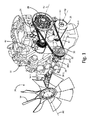
図1は、クラッチシステム20における一実施形態の斜視図であり、クラッチシステム20は内燃エンジン22と共に示されている。図1は原動機としての内燃エンジン22(例えば、ディーゼルエンジン)を示し、内燃エンジン22はクラッチシステム20にトルク入力を提供するが、他の実施形態では他のタイプの原動機も利用可能である。
FIG. 1 is a perspective view of an embodiment of the
図示の実施形態では、エンジン22はブロック24及び出力部材26を含み、該出力部材26はトルク出力を提供する。ブロック24はクラッチシステム20の複数の部分のために取り付け点を提供できる。出力部材26は典型的にはエンジン22から突出し、ベルト26-1に係合可能である。出力部材26の回転速度は作動中、エンジン22へのスロットル指令に依存して変化でき、この結果、クラッチシステム20への回転入力もまた変化する。
In the illustrated embodiment, the
クラッチシステム20は駆動トレインを提供し、該駆動トレインはクラッチ装置28、ベルト30、中間プーリ32、駆動シャフト34及び角度ギヤボックス36を含む。クラッチシステム20の駆動トレインはその最も下流端にて出力部材38に係合する。クラッチ装置28はエンジン22からベルト26-1を経てトルク入力を受け入れ、中間プーリ32にベルト30を介してトルクを選択的に伝達する。中間プーリ32は駆動シャフト34にトルクを伝達し、該駆動シャフト34は次に角度ギヤボックス36にトルクを伝達する。出力部材38がファンであるとき、該ファンはエンジン22に冷却空気流を向けるか、又は、可能な他の機能のなかでは熱交換器(図示しない)を通じて冷却空気流を移動させるべく位置付け可能である。
The
図示の実施形態では、クラッチ装置28はエンジン22のブロック24に対して、出力部材26に隣接又はその近傍に直接取り付けられている。ベルト26-1は出力部材26及びクラッチ装置28に結合している。また、図示の実施形態では、ベルト26-1にテンショナ40及び補機42(例えば発電機、空気調和圧縮機等)が結合されている。ベルト26-1の特定の配置やベルト26-1に共通して結合された特定の装置は特定の適用に際して所望されるとき、変更可能である。例えば、アンドラや他の構成部品もまたベルト26-1に係合可能である。
In the illustrated embodiment, the
図1に示されるように、中間プーリ32は回転軸線A1を備えて配置され、該回転軸線A1はクラッチ装置28の回転軸線A2(及び出力部材26の回転軸線A3)と平行(即ち、同一角度)であるが、クラッチ装置28の回転軸線A2からは或る距離を存してオフセットしている。更に、中間プーリ32はエンジン22から離間している。ベルト30はクラッチ装置28と中間プーリ32との間で結合されている。中間プーリ32の回転速度は、クラッチ装置28の出力速度を選択的に制御することで制御可能である。プーリのサイズは、中間プーリ32とクラッチ装置28の出力との間に所望の速度比を達成すべく選択可能である。
As shown in FIG. 1, the
駆動シャフトは中間プーリ32と角度ギヤボックス36との間で結合されている。図示の実施形態の駆動シャフト34は、長さが調整可能な主シャフト34-1、ユニバーサルジョイント34-2及び支持軸受34-3を含む。長さが調整可能な主シャフト34-1及びユニバーサルジョイント34-2の使用は多様な適用に際してシステム20の適合を許容し、そして、中間プーリ32と角度ギヤボックス36との間のオフセットを許容する(即ち、中間プーリ32の回転軸線A1は、角度ギヤボックス36への回転トルク軸線(図1に図示せず)からオフセット可能である)。システム20の構成部品の中でも、ユニバーサルジョイント34-2及び支持軸受34-3はシステム20の抗力(drag)及び慣性に寄与し、これら抗力及び慣性は一般的には損失と考えられるものの、本発明者等は以下に詳述するように、抗力及び慣性の特性がシステム20の特定の状況にて、或る利点を有することを明らかにした。
The drive shaft is coupled between the
一般的に、角度ギヤボックス36は、ベベルギヤ又は他の適切な機構を使用し、入力と出力との間で伝達されるトルクの空間的な方向付けを変更させる。図示の実施形態では、角度ギヤボックス36は直角ギヤボックスであって、伝達トルクの空間的な方向付けを90°だけ変更させ、代替の実施形態では別の角度でも可能である。角度ギヤボックス36は1:1のギヤ比を提供可能できるが(即ち、入力速度に対して出力速度の増減は無い)、代替の実施形態にて、特定の適用に際して所望されるならば、他のギヤ比も提供可能である。角度ギヤボックス36の出力はハブ又は出力シャフトを介して出力装置38(例えばファン)に作動的に受け取られ、回転軸線A4回りに出力装置38を駆動する。出力装置38の回転速度はクラッチ装置28によって管理される。このようにして出力装置38、角度ギヤボックス36の出力及び回転軸線A4は、クラッチ装置28及び/又はエンジン22の出力部材26の回転軸線A2,A3や、また、中間プーリ32の回転軸線A1とは異なる角度で空間的に方向付け可能となる。
Generally, the
クラッチ装置28は、エンジン20に対して直接的且つ物理的な取り付け係合をなし、そして、単一のベルト(ベルト26-1)がエンジン22とクラッチ装置28との間のトルク結合を提供する状態で、システム20の上流端又は従動端に位置付けることができる。このことは、クラッチシステム20における駆動トレインの最も上流位置にクラッチ装置28を配置することになる。このようにしてエンジン20から出力されたトルクはクラッチ装置28により、クラッチシステム20の入口で選択的に制御される。これに対して、従来技術のシステムは、下流端又は駆動端にクラッチ機構を含み、該クラッチ機構は角度ギヤボックス内に組み込まれているか、又は、ファン(即ち、出力部材)に直接取り付けられている。本発明の構成は、クラッチ装置28がシステム20における必須構成部品の全ての作動を管理するのを許容し、そして、システム20の他の構成部品へのトルクを選択的に停止するのを許容する。例えば、(システム20の駆動トレインにおいて、クラッチ装置28から下流に位置付けられた)角度ギヤボックス36へのトルク入力は、エンジン22の出力とは無関係にクラッチ装置28によって制御可能である。更に、駆動トレインの構成部品の中でも、駆動シャフト34におけるユニバーサルジョイント34-2及び支持軸受34-3、角度ギヤボックス36での噛み合うギヤ及び/又は中間プーリ32の抗力及び慣性の全てがクラッチ装置28の出力回転を制限し、それ故、クラッチ装置28の出力速度が増加する傾向を零に近付ける。クラッチシステム20における駆動トレインの下流部分の抗力及び慣性はクラッチ装置28における完全な「オフ」状態の提供を助け、「オフ」に切り換えられたとき、クラッチ装置28の出力、即ち、その回転は効果的に停止され、クラッチ装置28よりも向こう側/その下流のシステム20の構成部品の全てが本質的に停止可能となる(即ち、幾つか場合、出力装置38は非動力のファン風車となる)。これに対し、従来技術のシステムでは、駆動トレインの上流側の数多くの構成部分(駆動トレインの大部分の構成部品でないとしても)が(エンジンの駆動中)常時、回転する。
The
図1に示されたシステム20の実施形態が単に一例として提示され、限定されるものでないことに留意すべきである。例えば、他の実施形態では、付加的な中間プーリやベルトを備えることもでき、及び/又は、システムの構成部品間の相対的なスペースは特定の適用に際して適切に調整可能である。
It should be noted that the embodiment of
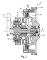
図2は、クラッチ装置28における一実施形態を個別に示す断面図である。図示の実施形態では、クラッチ装置28は、(固定の取り付けシャフトを備えた)ブラケット28-1、クラッチ(又はクラッチパック)28-2、及びプーリ28-3,28-4を含む。クラッチ28-2は、入力と出力との間でのトルクの選択的な伝達を提供する。クラッチ28-2は、米国特許番号8,887,888に開示された粘性クラッチと同様な構成の粘性クラッチである。このような粘性クラッチの構成は完全な可変滑り速度を許容する、即ち、クラッチ出力速度は、入力及び出力の構成要素間(例えば、ロータとハウジングとの間、ここで、該ハウジングはベース及びカバー備えたツーピースのハウジングからなる)の作動室に存在する剪断流体の容量を制御することで、本質的にクラッチ入力速度の0〜100%の所望の設定値に制御可能である。クラッチ装置28は、適切な制御部(図示しない)を使用して電子的に制御可能である。代替の実施形態では、活軸(live-shaft)粘性クラッチ、摩擦クラッチ、渦電流クラッチ又は他の適切なクラッチが利用可能である。
FIG. 2 is a cross-sectional view showing one embodiment of the
プーリ28-3,28-4はクラッチ28-2に係合されている。プーリ28-3はクラッチ28-2の入力部材として機能し、トルク入力を提供するベルト26-1に係合されている。プーリ28-4はクラッチ28-2の出力部材として機能し、トルク出力を(中間プーリ32に)伝達するベルト30に係合されている。図示の実施形態では、プーリ28-3,28-4は互いに平行に配置され、より詳しくは、回転の共通軸線(軸線A2)と同軸に配置されている。
The pulleys 28-3 and 28-4 are engaged with the clutch 28-2. The pulley 28-3 functions as an input member of the clutch 28-2 and is engaged with a belt 26-1 that provides torque input. The pulley 28-4 functions as an output member of the clutch 28-2 and is engaged with a
クラッチ28-2は複数の外側フィン28-5を含むことができ、これら外側フィン28-5は作動中、冷却空気流を発生し、クラッチ28-2によって発生された熱を散逸させる助けとなる。クラッチ28は、出力装置38として役立つファンから離れて位置付けられ、そして、著しい突き当て空気流に潜在的に晒されることがないので、熱を能動的に散逸する能力に有利なものとなる。フィン28-5はクラッチ装置28に対する熱負荷を比較的均一に分配して維持する助けとなる。
The clutch 28-2 can include a plurality of outer fins 28-5, which during operation generate a cooling air flow to help dissipate the heat generated by the clutch 28-2. .. The clutch 28 is positioned away from the fan serving as the
付け加えて、クラッチ28-2は、ブラケット28-1における固定の取り付けシャフトの先端又はその近傍にプーリ28-4とアライメントされた支持軸受セット28-6を含むことができ、該支持軸受セット28-6はベルト30からのベルト負荷を支持する助けとなる。同様に、ブラケット28-1における固定の取り付けシャフトの基端又はその近傍にはプーリ28-3とアライメントされた支持軸受セット28-7を含むことができ、該支持軸受セット28-7はベルト26-1からのベルト負荷を支持する助けとなる。
In addition, the clutch 28-2 may include a support bearing set 28-6 aligned with the pulley 28-4 at or near the tip of the fixed mounting shaft in the bracket 28-1, said support bearing set 28-. 6 helps to support the belt load from the
固定の取り付けシャフトは、ブラケット28-1の他の部分と一体的且つ一枚岩的に形成できるか、又は、ブラケット28-1を形成する1つ以上の他の部品に取り付けられた別個の部品である。 A fixed mounting shaft can be formed integrally and monolithically with other parts of bracket 28-1, or is a separate component attached to one or more other parts forming bracket 28-1. ..
図3,4は、試験室において実施された試験に基づき、従来技術に対する性能特性及び利点を表したグラフである。図3は、従来技術のクラッチシステムでの時間に対する速度のグラフであり、図4はクラッチシステム20の試作での時間に対する速度のグラフである。
3 and 4 are graphs showing the performance characteristics and advantages over the prior art based on the tests performed in the laboratory. FIG. 3 is a graph of speed with respect to time in the clutch system of the prior art, and FIG. 4 is a graph of speed with respect to time in the trial production of the
図3にグラフ化された従来技術では、直接検出且つ電子制御の粘性クラッチが直角ギヤボックスに直接に取り付けられ、そして、ファンが出力装置として直接検出且つ電子制御の粘性クラッチに直接に取り付けられた。換言すれば、粘性クラッチはファンに直に隣接した駆動トレインの下流に位置付けられた。図3のグラフは、入力速度(即ち、原動機からのトルク入力)をライン100、クラッチ速度指令をライン102、そして、ファン速度をライン104で描いている。粘性クラッチを使用する如何なるシステムでも、ファン速度(ライン104)が決して入力速度(ライン100)の100%に達することはなく、一般的には、ファン速度(ライン104)は、入力速度(ライン100)に密接に結び付けられた速度指令(ライン102)に順応する。しかしながら、システムの遅れが存在し、そして、ファン速度(ライン104)は零より相当大きな下限値に遭遇する。例えば、図3は2つの時間期間を表し、これら時間期間中、速度指令(ライン102)は零になってファンクラッチが「オフ」に切り換えられ、一方、入力速度(ライン100)は非零の状態を維持し、その時間中、ファン速度(ライン104)が約650 RPMの下限値106, 106’に低下することを示している。更にまた、零に低下する速度指令(ライン102)と下限値106, 106’に低下するファン速度(ライン104)との間にて、約1〜3分の遅れ時間が生じた。
In the prior art graphed in FIG. 3, a directly detected and electronically controlled viscous clutch was mounted directly on the right angle gearbox, and a fan was directly mounted as an output device on the directly detected and electronically controlled viscous clutch. .. In other words, the viscous clutch was located downstream of the drive train directly adjacent to the fan. In the graph of FIG. 3, the input speed (that is, the torque input from the prime mover) is drawn on
システム20の試作は図4のグラフを生成するために使用された。図4は入力速度(即ち、原動機からのトルク入力)をライン200、クラッチ速度指令をライン202、ファン速度をライン204で描いている。図4は多数の時間期間を表しており、これら時間期間中、速度指令(ライン202)は零になってファンクラッチが「オフ」に切り換えられ、一方、入力速度(ライン200)は非零の状態を維持し、該時間中、ファン速度(ライン204)は約0RPMの下限値206に低下する。更にまた、零に低下する速度指令(ライン202)と下限値206に低下するファン速度(ライン204)との間にて、約1〜1.5分の遅れ時間が生じた。
The prototype of
図3,4を比較すれば、システム20の下限値206が従来技術のシステムの下限値106, 106’よりも相当低いことは明らかである。そのうえ、システム20の遅れ時間は従来技術のシステムの遅れ時間と同等か又はそれよりも短い。このことは、システム20のクラッチ装置29の上流配置やシステム20における駆動トレインの下流の構成部品の抗力及び慣性等のパラメータの少なくとも一部に帰して、システム20の「オフ」応答時間に関して著しい改善を表す。
Comparing FIGS. 3 and 4, it is clear that the
(クラッチ装置を通過する)駆動トレイン全体を停止するのに有利な点が数多く存在する。これら有利な点は、殆ど零の出力装置(例えばファン)速度が得られることを含み、該ファン速度は寒中での適用に際して好都合であって、ノイズの低減を助け、そして、駆動トレインの構成部品における摩耗の低減を助ける。クラッチ装置28が「オフ」となり(即ち、トルク出力が零)、一方、寄生的な損失として働くことになる抗力及び慣性がクラッチ装置28及び出力装置38の出力を零の回転速度(又はその近傍)に、より詳しくは、従来技術のシステムよりも低い「オフ」速度に保持することで有益な作用を提供し、システム20における駆動トレインの下流にてエンジパワーの寄生的な損失が零になることで、寄生的な損失が最小化される。
There are many advantages to stopping the entire drive train (passing through the clutch device). These advantages include obtaining near zero output device (eg fan) speeds, which are convenient for cold weather applications, help reduce noise, and drive train components. Helps reduce wear in. The
当業者は、添付図面含む開示全体からみて本発明の数多くの他の利点や有益さを認識し得る。 One of ordinary skill in the art will recognize many other advantages and benefits of the invention in view of the entire disclosure, including the accompanying drawings.
可能な実施形態の検討
以下は、本発明における可能性があるものの排他的な実施形態の記述である。
原動機から駆動トレインに沿ってトルクを伝達するトルク伝達システムは、原動機からトルク入力を受け取るべく構成されたクラッチ装置と、該クラッチ装置と中間プーリとの間に作動的に係合されたベルトと、その入力及び出力間で伝達されるトルクの空間的方向付けを変更させる角度ギヤボックスと、該角度ギヤボックスからの出力されたトルクを受け取るべく構成された出力装置とを含むことができる。クラッチ装置は駆動トレインに沿い中間プーリ及び角度ギヤボックスの上流に位置付けられている。
Examination of Possible Embodiments The following is a description of possible but exclusive embodiments of the present invention.
A torque transmission system that transmits torque from a prime mover along a drive train includes a clutch device configured to receive torque input from the prime mover, a belt operatively engaged between the clutch device and an intermediate pulley, and It can include an angular gearbox that modifies the spatial orientation of the torque transmitted between its inputs and outputs, and an output device configured to receive the torque output from the angular gearbox. The clutch device is located along the drive train and upstream of the intermediate pulley and angle gearbox.
前記段落のシステムは、以下の特徴、構成及び/又は付加的な構成部品の1つ以上を選択的、付加的及び/又は代替的に含む、
・クラッチ装置は粘性クラッチを含み、
・クラッチ装置は、原動機からトルク入力を受け取る入力プーリと、クラッチ装置と中間プーリとの間に作動的に係合されたベルトにトルクを伝達する出力プーリとを含み、
・入力プーリ及び出力プーリは同軸的に配置可能であり、
・角度ギヤボックスは直角ギヤボックスであり、
・クラッチ装置はトルク伝達システムにおける駆動トレインの最も上流に位置付け可能であり、
・駆動シャフトはユニバーサルジョイントを含み、
・駆動トレインのクラッチ装置の下流に位置付けられた支持軸受、及び/又は
・出力装置はファンである。
The system in the paragraph above selectively, additionally and / or optionally comprises one or more of the following features, configurations and / or additional components:
・ The clutch device includes a viscous clutch
The clutch device includes an input pulley that receives torque input from the prime mover and an output pulley that transmits torque to a belt that is operatively engaged between the clutch device and the intermediate pulley.
-The input pulley and output pulley can be arranged coaxially.
・ The angle gearbox is a right angle gearbox.
-The clutch device can be positioned at the most upstream of the drive train in the torque transmission system.
・ The drive shaft includes a universal joint
-Support bearings located downstream of the drive train clutch device and / or-The output device is a fan.
駆動トレインに沿って原動機から出力装置にトルクを伝達する方法は、原動機からベルトにトルクを選択的に伝達するクラッチ装置を選択的に係合させ、ベルトで中間プーリを回転させ、中間プーリからのトルクで駆動シャフトを回転させ、駆動シャフトからのトルクを異なる空間的方向に角度ギヤボックスを介して向け直し、角度ギヤボックスから出力されたトルクで出力装置を回転させることを含むことができる。 The method of transmitting torque from the prime mover to the output device along the drive train is to selectively engage a clutch device that selectively transmits torque from the prime mover to the belt, rotate the intermediate pulley with the belt, and from the intermediate pulley. It can include rotating the drive shaft with torque, redirecting the torque from the drive shaft in different spatial directions through the angular gearbox, and rotating the output device with the torque output from the angular gearbox.
前記段落の方法は、以下の特徴、構成及び/又は付加的な構成部品の1つ以上を選択的、付加的及び/又は代替的に含む、
・駆動トレインの構成部品の特質を使用して出力装置の回転を制限し、ここでは、駆動トレインの構成部品の特質が抗力及び慣性からなるグループから選択される、
・駆動シャフトからのトルクが90°向け直され、及び/又は
・原動機からクラッチ装置へのトルクを提供する付加的なベルトを回転させる。
冷却システムは、内燃エンジンと、内燃エンジンからのトルクを伝達すべく構成された第1ベルトと、駆動トレインと、ファンとを含む。駆動トレインは、第1ベルトから出力されたトルクを受け取るべく構成されたクラッチ装置と、中間プーリと、クラッチ装置と中間プーリとの間に作動的に係合されたる第2ベルトと、その入力と出力との間で伝達されるトルクの空間的な方向付けを変更すべく構成された角度ギヤボックスと、中間プーリと角度ギヤボックスとの間に作動的に係合する駆動シャフトとを含む。クラッチ装置は駆動トレインに沿い中間プーリ及び角度ギヤボックスの上流に位置付けられている。ファンは駆動トレインから出力されたトルクを受け取るべく構成されている。
The method of the paragraph selectively comprises one or more of the following features, configurations and / or additional components, selectively, additionally and / or alternatives.
-Use the characteristics of the drive train components to limit the rotation of the output device, where the characteristics of the drive train components are selected from the group consisting of drag and inertia.
-Torque from the drive shaft is redirected 90 ° and / or-Rotates an additional belt that provides torque from the prime mover to the clutch device.
The cooling system includes an internal combustion engine, a first belt configured to transmit torque from the internal combustion engine, a drive train, and a fan. The drive train includes a clutch device configured to receive the torque output from the first belt, an intermediate pulley, a second belt operatively engaged between the clutch device and the intermediate pulley, and its input. It includes an angular gearbox configured to change the spatial orientation of torque transmitted to and from the output, and a drive shaft that operatively engages between the intermediate pulley and the angular gearbox. The clutch device is located along the drive train and upstream of the intermediate pulley and angle gearbox. The fan is configured to receive the torque output from the drive train.
前記段落のシステムは、以下の特徴、構成及び/又は付加的な構成部品の1つ以上を選択的、付加的及び/又は代替的に含む、
・クラッチ装置は粘性クラッチを含むことができ、
・クラッチ装置は、第1ベルトからトルク入力を受け取る入力プーリと、第2ベルトにトルクを伝達する出力プーリとを含むことができ、
・入力プーリ及び出力プーリは同軸的に配置でき、
・角度ギヤボックスは直角ギヤボックスであり、
・クラッチ装置はトルク伝達システムにおける駆動トレインの最も上流端に位置付け可能であり、
・駆動シャフトはユニバーサルジョイントを含むことができ、及び/又は
・クラッチ装置の下流に位置付けられた支持軸受。
The system in the paragraph above selectively, additionally and / or optionally comprises one or more of the following features, configurations and / or additional components:
・ The clutch device can include a viscous clutch,
The clutch device can include an input pulley that receives torque input from the first belt and an output pulley that transmits torque to the second belt.
・ Input pulley and output pulley can be arranged coaxially.
・ The angle gearbox is a right angle gearbox.
-The clutch device can be positioned at the most upstream end of the drive train in the torque transmission system.
The drive shaft can include universal joints and / or support bearings located downstream of the clutch device.
要約
ここで、「実質的」、「本質的」、「一般的」、「約」等の使用された相対的又は程度の語句は、明示的に述べられた適切な規定又は制限に応じて又は従い解釈されるべきである。全ての場合で、ここで使用された相対的又は程度の語句は、本開示全体に照らしてみて、熱や、回転的又は振動的な作動条件等によって誘発される製造誤差の変動、偶発的なアライメント変動、過渡的なアライメント又は形状の変動を包含することが当業者に認識されるように、関連して開示された実施形態や、範囲又は変動を広く含んで解釈されるべきである。そのうえ、ここで使用された相対的又は程度の語句は、所定の開示又は引用において相対的又は程度の語句を制限していないなら、指定の品質、特性、パラメータ又は値を明示的に含む範囲を変動無く包含するように解釈されるべきである。
Summary Here, the relative or degree terms used, such as "substantial,""essential,""general,""about," etc., are used in accordance with the appropriate provisions or restrictions explicitly stated. It should be interpreted accordingly. In all cases, the terms relative or degree used herein are, in the light of the entire disclosure, variations in manufacturing error, accidental, caused by heat, rotational or oscillating operating conditions, etc. It should be broadly interpreted to include the relevant disclosed embodiments, ranges or variations so that those skilled in the art will recognize that they include alignment variations, transient alignments or shape variations. Moreover, the relative or degree terms used herein include a range that explicitly includes the specified quality, characteristics, parameters or values, provided that the relative or degree terms are not restricted in the given disclosure or citation. It should be interpreted to include without change.
本発明は好適な実施形態を参照して記載されたが、当業者は本発明の趣旨や範囲から逸脱することなしに、形態や詳細の変更がなされることを認識している。 Although the present invention has been described with reference to preferred embodiments, those skilled in the art will recognize that modifications will be made in embodiments and details without departing from the spirit and scope of the invention.
Claims (16)
前記原動機からトルク入力を受け取るべく構成されたクラッチ装置であって、前記原動機からのトルク入力を受け取る入力プーリを備えている粘性クラッチを含むクラッチ装置と、
出力プーリであって、前記入力プーリと同軸的に配置される出力プーリと、
中間プーリと、
前記出力プーリと前記中間プーリとの間に作動的に係合されたベルトと、
その入力と出力との間で伝達されるトルクの空間的な方向付けを変更すべく構成された角度ギヤボックスと、
前記中間プーリと前記角度ギヤボックスとの間に作動的に係合された駆動シャフトと、
前記角度ギヤボックスから出力されたトルクを受け取るべく構成された出力装置を具備し、前記出力装置がファンであり、
前記クラッチ装置は、前記駆動トレインに沿い前記中間プーリ及び前記角度ギヤボックスの上流に位置付けられている、トルク伝達システム。 A torque transmission system that transmits torque from the prime mover along the drive train.
A clutch device configured to receive torque input from the prime mover, including a viscous clutch including an input pulley for receiving torque input from the prime mover.
An output pulley that is coaxial with the input pulley and
With the intermediate pulley
A belt operatively engaged between the output pulley and the intermediate pulley,
An angular gearbox configured to change the spatial orientation of the torque transmitted between its inputs and outputs,
A drive shaft operatively engaged between the intermediate pulley and the angle gearbox,
The output device is provided with an output device configured to receive the torque output from the angle gearbox , and the output device is a fan .
The clutch device is a torque transmission system located upstream of the intermediate pulley and the angle gearbox along the drive train.
前記原動機からベルトにトルクを選択的に伝達するためにクラッチ装置を選択的に係合させ、前記クラッチ装置は電子的に制御可能な粘性クラッチ装置であり、前記電子的に制御可能な粘性クラッチ装置の選択的な係合は、速度指令を受け取り、入力の構成と出力の構成との間の作動室内に存在する剪断流体の容量を制御することを含んでおり、
前記ベルトで中間プーリを回転させ、
前記中間プーリからのトルクで駆動シャフトを回転させ、
前記駆動シャフトからのトルクを異なる空間的方向に角度ギヤボックスを介して向け直し、
前記角度ギヤボックスからのトルクで前記出力装置を回転させ、
前記クラッチ装置をオフにする速度指令を受け取り、そして
前記クラッチ装置をオフにする速度指令を受け取った後に、駆動トレインの構成部品の特質を使用して前記出力装置の回転を制限しており、前記駆動トレインの構成部品の前記特質は抗力及び慣性からなるグループから選択される、
ことを具備する方法。 A method of transmitting torque from the prime mover to the output device along the drive train.
A clutch device is selectively engaged in order to selectively transmit torque from the prime mover to the belt, and the clutch device is an electronically controllable viscous clutch device, and the electronically controllable viscous clutch device. Selective engagement involves receiving speed commands and controlling the volume of shear fluid present in the working chamber between the input and output configurations.
Rotate the intermediate pulley with the belt
The drive shaft is rotated by the torque from the intermediate pulley,
The torque from the drive shaft is redirected in different spatial directions via the angular gearbox.
The output device is rotated by the torque from the angle gearbox ,
Receives a speed command to turn off the clutch device, and
After receiving the speed command to turn off the clutch device, the characteristics of the drive train components are used to limit the rotation of the output device, and the characteristics of the drive train components are due to drag and inertia. Selected from the group
How to equip that.
内燃エンジンと、
前記内燃エンジンからトルクを伝達すべく構成された第1ベルトと、
駆動トレインであって、
前記第1ベルトからトルク入力を受け取るべく構成されたクラッチ装置と、
中間プーリと、
前記クラッチ装置と前記中間プーリとの間に作動的に係合された第2ベルトと、
その入力と出力との間で伝達されるトルクの空間的な方向付けを変更すべく構成された角度ギヤボックスと、
前記中間プーリと前記角度ギヤボックスとの間に作動的に係合された駆動シャフトと
を含み、前記クラッチ装置が前記駆動トレインに沿い前記中間プーリ及び前記角度ギヤボックスの上流に位置付けられている、駆動トレインと、
前記駆動トレインからトルク出力を受け取るべく構成されたファンと
を具備する冷却システム。 In the cooling system
With an internal combustion engine
A first belt configured to transmit torque from the internal combustion engine and
It ’s a drive train,
A clutch device configured to receive torque input from the first belt, and
With the intermediate pulley
A second belt operatively engaged between the clutch device and the intermediate pulley,
An angular gearbox configured to change the spatial orientation of the torque transmitted between its inputs and outputs,
A drive shaft operably engaged between the intermediate pulley and the angle gearbox is included, and the clutch device is positioned along the drive train upstream of the intermediate pulley and the angle gearbox. With the drive train
A cooling system including a fan configured to receive torque output from the drive train.
前記第1ベルトからトルク入力を受け取る入力プーリと、
前記第2ベルトにトルクを伝達する出力プーリと
を含む、請求項9に記載のシステム。 The clutch device is
An input pulley that receives torque input from the first belt,
9. The system of claim 9 , comprising an output pulley that transmits torque to the second belt.
前記駆動シャフトに沿うユニバーサルジョイントと、
前記クラッチ装置の下流に位置付けられた支持軸受と
を更に含む、請求項9に記載のシステム。 The drive train
A universal joint along the drive shaft,
9. The system of claim 9 , further comprising a support bearing located downstream of the clutch device.
Applications Claiming Priority (3)
| Application Number | Priority Date | Filing Date | Title |
|---|---|---|---|
| US201562163659P | 2015-05-19 | 2015-05-19 | |
| US62/163,659 | 2015-05-19 | ||
| PCT/US2016/032391 WO2016187016A2 (en) | 2015-05-19 | 2016-05-13 | Angled torque transmission system and method |
Publications (3)
| Publication Number | Publication Date |
|---|---|
| JP2018516798A JP2018516798A (en) | 2018-06-28 |
| JP2018516798A5 JP2018516798A5 (en) | 2019-05-09 |
| JP6760963B2 true JP6760963B2 (en) | 2020-09-23 |
Family
ID=57320309
Family Applications (1)
| Application Number | Title | Priority Date | Filing Date |
|---|---|---|---|
| JP2017557037A Active JP6760963B2 (en) | 2015-05-19 | 2016-05-13 | Angled torque transmission system and method |
Country Status (10)
| Country | Link |
|---|---|
| US (1) | US10589619B2 (en) |
| EP (1) | EP3298258B1 (en) |
| JP (1) | JP6760963B2 (en) |
| KR (1) | KR102276836B1 (en) |
| CN (1) | CN107709731B (en) |
| AU (1) | AU2016263118B2 (en) |
| CA (1) | CA2984805C (en) |
| MX (1) | MX2017014107A (en) |
| WO (1) | WO2016187016A2 (en) |
| ZA (1) | ZA201707997B (en) |
Families Citing this family (7)
| Publication number | Priority date | Publication date | Assignee | Title |
|---|---|---|---|---|
| AU2017330214B2 (en) | 2016-09-23 | 2019-08-08 | Horton, Inc. | Modular viscous clutch |
| US11052723B2 (en) * | 2017-10-19 | 2021-07-06 | B & D Technologies, LLC | Air conditioning system for use with unenclosed mowers |
| US11333207B2 (en) | 2018-05-09 | 2022-05-17 | Horton, Inc. | Shaft output viscous clutch |
| WO2020263553A1 (en) * | 2019-06-28 | 2020-12-30 | Horton, Inc. | Transmission system with planetary gearing operable in forward and reverse modes |
| CN114930043A (en) * | 2020-01-21 | 2022-08-19 | 霍顿公司 | Clutch assembly and integrated anti-rotation bracket/guard |
| US11459933B2 (en) | 2020-09-28 | 2022-10-04 | Horton, Inc. | Accessible clutch attachment assembly and method |
| CN112483237B (en) * | 2020-12-08 | 2022-01-11 | 湖南行必达网联科技有限公司 | Electric control silicone oil fan control method, device and system and vehicle |
Family Cites Families (48)
| Publication number | Priority date | Publication date | Assignee | Title |
|---|---|---|---|---|
| US575637A (en) | 1897-01-19 | Fan for baby-carriages | ||
| US918782A (en) | 1908-03-28 | 1909-04-20 | George Siffert | Perambulator or vehicle. |
| US1411126A (en) | 1921-03-15 | 1922-03-28 | Victor W Page | Fan drive |
| US1991575A (en) | 1934-01-20 | 1935-02-19 | Gen Motors Corp | Cross engine drive |
| US2230165A (en) | 1939-10-12 | 1941-01-28 | Allen Jack | Fan attachment for land vehicles |
| FR1595882A (en) | 1968-12-02 | 1970-06-15 | ||
| GB1267436A (en) * | 1969-10-22 | 1972-03-22 | A C M Engineers Ltd Formerly A | Governed power take-off apparatus for internal combustion engines |
| FR2192466A5 (en) | 1972-07-07 | 1974-02-08 | Tecnoma | |
| DE2521331C2 (en) | 1975-05-13 | 1990-03-29 | Zahnräderfabrik Renk AG, 8900 Augsburg | Transmission for full-track vehicles |
| JPS52105748U (en) * | 1976-02-07 | 1977-08-11 | ||
| JPS52105748A (en) * | 1976-03-01 | 1977-09-05 | Nec Corp | Transformer circuit |
| US4157135A (en) | 1977-11-21 | 1979-06-05 | General Motors Corporation | Clutch lock-up mechanism |
| JPS615046Y2 (en) * | 1980-01-24 | 1986-02-17 | ||
| JPS56111603A (en) * | 1980-02-07 | 1981-09-03 | Meinan Machinery Works | Method and device for stacking veneer |
| GB2098146B (en) | 1981-04-30 | 1984-11-07 | Metro Cammell Weymann Ltd | Rear-engined vehicles |
| DE3236794C2 (en) | 1982-10-05 | 1986-01-23 | M.A.N. Maschinenfabrik Augsburg-Nürnberg AG, 8000 München | Cooler-fan system, especially for buses with a vehicle engine in the rear |
| US4756208A (en) | 1986-01-08 | 1988-07-12 | Kubota, Ltd. | Mid-mount tractor |
| GB2188963B (en) * | 1986-04-14 | 1989-11-22 | Johnston Eng Ltd | Improvements in or relating to road sweeping vehicles |
| FR2673242B1 (en) | 1991-02-21 | 1995-01-20 | Valeo Thermique Moteur Sa | MOUNTING OF A MOTOR-FAN GROUP ON A MOTOR VEHICLE COOLING RADIATOR. |
| JP3294120B2 (en) * | 1996-08-21 | 2002-06-24 | 株式会社デンソー | Vehicle heating system |
| JPH10225925A (en) * | 1997-02-14 | 1998-08-25 | Kioritz Corp | Power-driven cutter and centrifugal clutch for power-driven cutter |
| US7192376B2 (en) | 1997-03-12 | 2007-03-20 | Norihiro Ishii | Axle driving apparatus |
| EP0967104A3 (en) | 1998-06-17 | 2001-03-21 | Baruffaldi S.p.A. | Apparatus with directable blades for conveying air to radiators of motor vehicles and the like |
| DE10030607A1 (en) | 2000-06-21 | 2002-01-03 | Linnig Antriebstechnik Gmbh | Gearbox for converting rotational movement into translation movement has linear gearing with two gearwheels on common shaft driven at different speeds with one secured to common shaft |
| GB0017785D0 (en) * | 2000-07-21 | 2000-09-06 | Gibbs Tech Ltd | Power take off |
| JP2002081523A (en) | 2000-09-05 | 2002-03-22 | Kubota Corp | Transmission for work vehicle |
| US6439172B1 (en) * | 2001-01-24 | 2002-08-27 | Borg Warner, Inc. | Water-cooled remote fan drive |
| EP1248007B1 (en) | 2001-04-06 | 2004-01-14 | BorgWarner Inc. | Viscous coupling |
| AU2002329966A1 (en) | 2001-09-04 | 2003-03-18 | Paul E. Arlton | Rotor system for helicopters |
| CN2538594Y (en) | 2002-03-28 | 2003-03-05 | 孙福生 | Power transmission clutch for combine |
| CN2752453Y (en) | 2004-05-16 | 2006-01-18 | 王永钦 | Assembly of vehicle cooling fan driving mechanism |
| DE202007001923U1 (en) | 2007-02-09 | 2007-04-12 | Karl Heinz Linnig Gmbh & Co Kg | Drive system for engine cooling of heavy motor vehicles e.g. for omnibus, has single stage electromagnetic coupling arranged between gear and fan, whereby eddy-current coupling is mounted on single stage electromagnetic coupling |
| ITMI20070379A1 (en) | 2007-02-27 | 2008-08-28 | Baruffaldi Spa | BIDIRECTIONAL CONICAL GROUP FOR MOTORCYCLE TRANSMISSION FROM A CRANKSHAFT TO A DRIVE SHAFT |
| US8111028B2 (en) | 2007-10-10 | 2012-02-07 | Prime Datum, Inc. | Integrated fan drive system for cooling tower |
| WO2009067048A1 (en) | 2007-11-20 | 2009-05-28 | Volvo Aero Corporation | Gas turbine engine |
| JP2009210097A (en) * | 2008-03-06 | 2009-09-17 | Hitachi Ltd | Viscous fluid joint |
| DE202008005470U1 (en) | 2008-04-18 | 2008-08-07 | Linnig Antriebstechnik Gmbh | Friction clutch and drive system for cooling an internal combustion engine of a vehicle with a friction clutch |
| CN201265448Y (en) | 2008-09-04 | 2009-07-01 | 中顺汽车控股有限公司 | Vehicle cooling fan actuating mechanism |
| CN102667213B (en) | 2009-11-17 | 2015-02-11 | 霍顿公司 | Integrated viscous clutch |
| US8732947B2 (en) * | 2010-02-25 | 2014-05-27 | Kit Masters Inc. | Method for accessing components of a fan clutch system |
| JPWO2012005254A1 (en) | 2010-07-09 | 2013-10-03 | 日産自動車株式会社 | Driving force distribution control device |
| KR101204942B1 (en) * | 2012-06-05 | 2012-11-26 | 삼건세기(주) | Energy saving type clutch assembly |
| EP2892749A1 (en) * | 2012-09-04 | 2015-07-15 | Clark Equipment Company | Front power takeoff for utility vehicle |
| US9777639B2 (en) * | 2012-12-23 | 2017-10-03 | United Technologies Corporation | Turbine engine gearbox mount with multiple fuse joints |
| CN203067072U (en) * | 2013-01-29 | 2013-07-17 | 安徽安凯汽车股份有限公司 | Cooling system for passenger car engine |
| CN203090461U (en) | 2013-01-31 | 2013-07-31 | 苏州益童游乐设备有限公司 | Wind power toy car |
| WO2014158397A1 (en) | 2013-03-14 | 2014-10-02 | Horton, Inc. | Viscous clutch with minimum output speed |
| CN103967579B (en) | 2014-03-18 | 2018-12-18 | 龙口中宇热管理系统科技有限公司 | Angle is driven cooling device |
-
2016
- 2016-05-13 US US15/570,813 patent/US10589619B2/en active Active
- 2016-05-13 MX MX2017014107A patent/MX2017014107A/en unknown
- 2016-05-13 AU AU2016263118A patent/AU2016263118B2/en active Active
- 2016-05-13 CN CN201680028492.2A patent/CN107709731B/en active Active
- 2016-05-13 KR KR1020177036630A patent/KR102276836B1/en active IP Right Grant
- 2016-05-13 CA CA2984805A patent/CA2984805C/en active Active
- 2016-05-13 EP EP16797012.8A patent/EP3298258B1/en active Active
- 2016-05-13 JP JP2017557037A patent/JP6760963B2/en active Active
- 2016-05-13 WO PCT/US2016/032391 patent/WO2016187016A2/en active Application Filing
-
2017
- 2017-11-24 ZA ZA2017/07997A patent/ZA201707997B/en unknown
Also Published As
| Publication number | Publication date |
|---|---|
| CA2984805C (en) | 2021-10-19 |
| CN107709731B (en) | 2020-07-31 |
| KR102276836B1 (en) | 2021-07-12 |
| JP2018516798A (en) | 2018-06-28 |
| MX2017014107A (en) | 2018-03-16 |
| KR20180000736A (en) | 2018-01-03 |
| AU2016263118A1 (en) | 2017-12-07 |
| AU2016263118B2 (en) | 2020-01-30 |
| EP3298258B1 (en) | 2020-04-01 |
| WO2016187016A3 (en) | 2018-02-08 |
| EP3298258A4 (en) | 2019-05-22 |
| CN107709731A (en) | 2018-02-16 |
| CA2984805A1 (en) | 2016-11-24 |
| WO2016187016A2 (en) | 2016-11-24 |
| ZA201707997B (en) | 2018-11-28 |
| BR112017024155A2 (en) | 2018-07-17 |
| US20180162217A1 (en) | 2018-06-14 |
| US10589619B2 (en) | 2020-03-17 |
| EP3298258A2 (en) | 2018-03-28 |
Similar Documents
| Publication | Publication Date | Title |
|---|---|---|
| JP6760963B2 (en) | Angled torque transmission system and method | |
| CN1926357B (en) | Dual ratio belt drive system | |
| US8454463B2 (en) | Engine powered device having accessory drive and reversing motor for selectively starting engine and powering accessory drive | |
| US9181850B2 (en) | Hybrid fan drive with CVT and electric motor | |
| MX2008011512A (en) | Variable ratio belt drive system. | |
| JP6952119B2 (en) | Auxiliary belt transmission system with multiple gear ratios and torque reversals | |
| JPH04166619A (en) | Accessory driving device in power unit | |
| JP4124596B2 (en) | Water-cooled remote control fan drive assembly and method for improving its cooling capacity | |
| US7568888B2 (en) | Fan blades having variable pitch compliantly responsive to a linear actuator | |
| US8256550B2 (en) | Cooling device for vehicle | |
| US20160121899A1 (en) | System with slippable torque-transmission device connecting engine crankshaft and engine-driven component and vehicle | |
| CN103154465B (en) | Device for transmitting mechanical torque between a driving member and a driven member, and air-compression system for supplying power to an engine using such a device | |
| BR112017024155B1 (en) | TORQUE TRANSMISSION METHOD AND SYSTEM FOR TRANSMITTING TORQUE FROM A MOTOR AGENT | |
| CN109690133B (en) | Endless drive and improved two-arm tensioning system for an endless drive | |
| US20080216598A1 (en) | Coupling shaft adaptor for harmonic balancer | |
| JP2015140878A (en) | Structure for transmitting power from vehicle engine to auxiliary equipment | |
| US20180363544A1 (en) | Shaft driven engine accessories | |
| CN108944344A (en) | A kind of improved fuel oil Air conditioner on car system | |
| US6789654B2 (en) | Multiple coupling fan drive | |
| JPS5934501Y2 (en) | Vehicle cooling system | |
| JP2019156069A (en) | Gear device for diesel railcar | |
| JP2008164154A (en) | Damper pulley | |
| EP3201452A1 (en) | Shaft driven engine accessories | |
| SE525088C2 (en) | Vehicles with engine-driven auxiliary units | |
| JP2000205355A (en) | Autotensioner |
Legal Events
| Date | Code | Title | Description |
|---|---|---|---|
| A521 | Request for written amendment filed |
Free format text: JAPANESE INTERMEDIATE CODE: A523 Effective date: 20190320 |
|
| A621 | Written request for application examination |
Free format text: JAPANESE INTERMEDIATE CODE: A621 Effective date: 20190320 |
|
| A977 | Report on retrieval |
Free format text: JAPANESE INTERMEDIATE CODE: A971007 Effective date: 20200225 |
|
| A131 | Notification of reasons for refusal |
Free format text: JAPANESE INTERMEDIATE CODE: A131 Effective date: 20200311 |
|
| A521 | Request for written amendment filed |
Free format text: JAPANESE INTERMEDIATE CODE: A523 Effective date: 20200605 |
|
| TRDD | Decision of grant or rejection written | ||
| A01 | Written decision to grant a patent or to grant a registration (utility model) |
Free format text: JAPANESE INTERMEDIATE CODE: A01 Effective date: 20200805 |
|
| A61 | First payment of annual fees (during grant procedure) |
Free format text: JAPANESE INTERMEDIATE CODE: A61 Effective date: 20200903 |
|
| R150 | Certificate of patent or registration of utility model |
Ref document number: 6760963 Country of ref document: JP Free format text: JAPANESE INTERMEDIATE CODE: R150 |
|
| R250 | Receipt of annual fees |
Free format text: JAPANESE INTERMEDIATE CODE: R250 |