JP6760351B2 - In-vehicle short-range wireless communication device, master unit, and slave unit - Google Patents
In-vehicle short-range wireless communication device, master unit, and slave unit Download PDFInfo
- Publication number
- JP6760351B2 JP6760351B2 JP2018204069A JP2018204069A JP6760351B2 JP 6760351 B2 JP6760351 B2 JP 6760351B2 JP 2018204069 A JP2018204069 A JP 2018204069A JP 2018204069 A JP2018204069 A JP 2018204069A JP 6760351 B2 JP6760351 B2 JP 6760351B2
- Authority
- JP
- Japan
- Prior art keywords
- mobile terminal
- unit
- vehicle
- wireless communication
- slave
- Prior art date
- Legal status (The legal status is an assumption and is not a legal conclusion. Google has not performed a legal analysis and makes no representation as to the accuracy of the status listed.)
- Active
Links
Images


Classifications
-
- Y—GENERAL TAGGING OF NEW TECHNOLOGICAL DEVELOPMENTS; GENERAL TAGGING OF CROSS-SECTIONAL TECHNOLOGIES SPANNING OVER SEVERAL SECTIONS OF THE IPC; TECHNICAL SUBJECTS COVERED BY FORMER USPC CROSS-REFERENCE ART COLLECTIONS [XRACs] AND DIGESTS
- Y02—TECHNOLOGIES OR APPLICATIONS FOR MITIGATION OR ADAPTATION AGAINST CLIMATE CHANGE
- Y02D—CLIMATE CHANGE MITIGATION TECHNOLOGIES IN INFORMATION AND COMMUNICATION TECHNOLOGIES [ICT], I.E. INFORMATION AND COMMUNICATION TECHNOLOGIES AIMING AT THE REDUCTION OF THEIR OWN ENERGY USE
- Y02D30/00—Reducing energy consumption in communication networks
- Y02D30/70—Reducing energy consumption in communication networks in wireless communication networks
Description
本発明は、車載近距離無線通信装置、親機、及び子機に関するものである。The present invention relates to an in-vehicle short-range wireless communication device , a master unit, and a slave unit .
従来、特許文献1に開示されているように、ユーザが携帯する携帯端末と車両に搭載された近距離無線通信装置との無線通信を用いて、ハンズフリー通話などの種々のサービスをユーザが受けられるようにする技術が知られている。 Conventionally, as disclosed in Patent Document 1, a user receives various services such as hands-free calling by using wireless communication between a mobile terminal carried by the user and a short-range wireless communication device mounted on a vehicle. The technology to make it possible is known.
携帯端末と近距離無線通信装置との無線通信を用いたサービスは、特許文献1に開示のハンズフリー通話といった車室内に限るサービスだけではない。例えば、車両に関するデータを車外で受け取るデータ通信などのサービスの需要も今後見込まれる。サービスの種類によっては、近距離無線通信装置を車両に複数台搭載し、この複数台の近距離無線通信装置の各々で携帯端末から受信する電波の強度などから携帯端末の位置を推定したりすることも必要になると考えられる。 Services using wireless communication between a mobile terminal and a short-range wireless communication device are not limited to services limited to the vehicle interior, such as hands-free calling disclosed in Patent Document 1. For example, demand for services such as data communication that receives data on vehicles outside the vehicle is expected in the future. Depending on the type of service, multiple short-range wireless communication devices may be installed in the vehicle, and the position of the mobile terminal may be estimated from the strength of radio waves received from the mobile terminal by each of these multiple short-range wireless communication devices. It is thought that this will also be necessary.
本発明は、車両のどの方位に位置する携帯端末も検知できる車載近距離無線通信装置、 親機、及び子機を提供することを目的としている。An object of the present invention is to provide an in-vehicle short-range wireless communication device , a master unit, and a slave unit that can detect a mobile terminal located in any direction of a vehicle.
本発明の車載近距離無線通信装置は、車両に搭載され、どの位置に携帯端末が存在するか位置検出するための車載近距離無線通信装置であって、通信範囲に位置する携帯端末と通信接続して近距離無線通信を行う装置として、1台の親機(1)と、複数台の子機(2a,2b,2c)とを有し、親機は、車両に対して全周範囲の通信範囲を持ち、その通信範囲に位置する携帯端末を検知する携帯端末検知部(13)を有し、複数台の子機は、それぞれ車両の右側と左側に配置され、上記通信範囲と異なる通信範囲を持ち、親機は、自身が携帯端末と通信接続されると、複数台の子機の電源供給をオンに切り替えて、複数台の子機にて携帯端末からの電波の受信を開始させ、複数台の子機で受信した電波から位置検出させる起動制御部(14)を備えることを特徴としている。
本発明の親機は、車両に搭載され、どの位置に携帯端末が存在するか位置検出するための車載近距離無線通信装置に用いられる親機であって、通信範囲に位置する携帯端末と通信接続して近距離無線通信を行う装置としての親機であり、車両に対して全周範囲の通信範囲を持ち、その通信範囲に位置する携帯端末を検知する携帯端末検知部(13)と、親機は、自身が携帯端末と通信接続されると、それぞれ車両の右側と左側に配置されて上記通信範囲と異なる通信範囲を持つ、通信範囲に位置する携帯端末と通信接続して近距離無線通信を行う装置としての複数台の子機の電源供給をオンに切り替えて、複数台の子機にて携帯端末からの電波の受信を開始させ、複数台の子機で受信した電波から位置検出させる起動制御部(14)とを備えることを特徴としている。
本発明の子機は、車両に搭載され、どの位置に携帯端末が存在するか位置検出するための車載近距離無線通信装置に用いられる子機であって、通信範囲に位置する携帯端末と通信接続して近距離無線通信を行う装置としての、それぞれ車両の右側と左側に配置されるうちのいずれかの子機であって、車両の右側と左側に配置されるそれらの複数台で受信した電波から位置検出が行われる子機であり、車両に対して全周範囲の通信範囲を持ってその通信範囲に位置する携帯端末を検知する親機の通信範囲と異なる通信範囲を持ち、親機が携帯端末と通信接続される場合に、電源供給をオンに切り替えて携帯端末からの電波の受信を開始させることを特徴としている。
The in-vehicle short-range wireless communication device of the present invention is an in-vehicle short-range wireless communication device mounted on a vehicle and for detecting the position of a mobile terminal, and is connected to a mobile terminal located in a communication range. As a device for performing short-range wireless communication, it has one master unit (1) and a plurality of slave units (2a, 2b, 2c), and the master unit covers the entire circumference of the vehicle. It has a communication range and has a mobile terminal detection unit (13) that detects a mobile terminal located in the communication range, and a plurality of slave units are arranged on the right side and the left side of the vehicle, respectively, and communication different from the above communication range. Having a range, when the master unit is connected to the mobile terminal by communication, the power supply of multiple slave units is switched on, and the multiple slave units start receiving radio waves from the mobile terminal. It is characterized by including an activation control unit (14) that detects a position from radio waves received by a plurality of slave units.
The master unit of the present invention is a master unit mounted on a vehicle and used in an in-vehicle short-range wireless communication device for detecting the position of a mobile terminal, and communicates with a mobile terminal located in a communication range. A mobile terminal detector (13), which is a master unit as a device for connecting and performing short-range wireless communication, has a communication range of the entire circumference with respect to the vehicle, and detects a mobile terminal located in the communication range. When the master unit is connected to the mobile terminal by communication, the master unit communicates with the mobile terminal located in the communication range, which is arranged on the right side and the left side of the vehicle and has a communication range different from the above communication range, respectively, for short-range wireless communication. The power supply of multiple slave units as a communication device is switched on, the reception of radio waves from the mobile terminal is started by the multiple slave units, and the position is detected from the radio waves received by the multiple slave units. It is characterized in that it is provided with an activation control unit (14) to be operated.
The slave unit of the present invention is a slave unit mounted on a vehicle and used in an in-vehicle short-range radio communication device for detecting the position of a mobile terminal, and communicates with a mobile terminal located within a communication range. of the apparatus for performing short-range wireless communication by connecting, it either handset der of which is disposed on the right and left sides of the vehicle respectively, radio waves received by a plurality thereof are arranged on the right and left sides of the vehicle It is a slave unit whose position is detected from, and has a communication range that is different from the communication range of the master unit that has a communication range of the entire circumference with respect to the vehicle and detects a mobile terminal located in that communication range. When a communication connection is made with a mobile terminal, the power supply is switched on to start receiving radio waves from the mobile terminal.
(実施形態1)
<近距離無線通信システム100の概略構成>
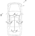
以下、本発明の実施形態について図面を用いて説明する。図1は、本発明が適用された近距離無線通信システム100の概略的な構成の一例を示す図である。図1に示すように、近距離無線通信システム100は、車両Aに搭載された親機としての近距離無線通信装置(以下、親機1)、子機としての複数台の近距離無線通信装置(以下、子機2a〜2c)、及び携帯端末3を含んでいる。親機1と子機2a〜2cとは、例えば車載LAN等で接続されている。この親機と子機2a〜2cが請求項の近距離無線通信システムに相当する。
(Embodiment 1)
<Rough configuration of short-range
Hereinafter, embodiments of the present invention will be described with reference to the drawings. FIG. 1 is a diagram showing an example of a schematic configuration of a short-range
携帯端末3は、ユーザが携帯して持ち運ぶことができる多機能携帯電話機等の携帯端末である。親機1及び子機2a〜2cは、前述したように車両Aに搭載されるものであって、自装置の通信範囲に位置する携帯端末3と通信接続して無線通信を行う。また、親機1は、子機2a〜2cの起動を制御し、子機2a〜2cは、車両Aに搭載された機器を制御して、携帯端末3との間での無線通信を用いたサービスを行う。
The mobile terminal 3 is a mobile terminal such as a multifunctional mobile phone that the user can carry and carry. The master unit 1 and the
サービスの一例としては、携帯端末3で通話を行う代わりに車両Aに搭載されたスピーカおよびマイクを用いて通話を行うハンズフリー通話、携帯端末3に記憶されている楽曲をカーオーディオで再生させるオーディオストリーミングがある。また、車両Aの機器から携帯端末3が情報を取得するデータ通信、携帯端末3から車両Aの機器を操作するリモート操作もある。データ通信で携帯端末3が取得する情報の一例としては、車両Aの平均燃費や走行距離やタイヤ空気圧などが挙げられる。リモート操作の一例としては、車外からカーエアコンを起動させる操作などが挙げられる。 As an example of the service, a hands-free call is made by using a speaker and a microphone mounted on the vehicle A instead of making a call by the mobile terminal 3, and an audio that reproduces a music stored in the mobile terminal 3 by car audio. There is streaming. There is also data communication in which the mobile terminal 3 acquires information from the device of the vehicle A, and remote operation of operating the device of the vehicle A from the mobile terminal 3. Examples of the information acquired by the mobile terminal 3 in the data communication include the average fuel consumption, the mileage, and the tire pressure of the vehicle A. An example of remote operation is an operation of starting a car air conditioner from outside the vehicle.
子機2a〜2cは、それぞれ車両Aの異なる位置に搭載されており、それぞれ通信範囲が異なっている。例えば、子機2aは、車両Aの左側方寄りの位置に搭載されており、車両Aの左側方寄りの車室内から車室外までを通信範囲としている。子機2bは、車両Aの右側方寄りの位置に搭載されており、車両Aの右側方寄りの車室内から車室外までを通信範囲としている。子機2cは、車両Aの後方寄りの位置に搭載されており、車両Aの後方寄りの車室内から車室外までを通信範囲としている。
The
なお、以降では、子機2a〜2cを区別しない場合には子機2と呼ぶものとする。本実施形態では、近距離無線通信システム100において子機2を3台含む構成を示したが、必ずしもこれに限らず、複数台であれば3台以外の数の子機2を近距離無線通信システム100に含む構成としてもよい。
Hereinafter, when the
<親機1の概略構成>
ここで、図2を用いて、親機1の概略的な構成の一例について説明を行う。図2に示すように、親機1は、無線通信部11、携帯端末検知部13、子機起動制御部14、及び端末位置推定部15を備えている。
<Outline configuration of master unit 1>
Here, an example of a schematic configuration of the master unit 1 will be described with reference to FIG. As shown in FIG. 2, the master unit 1 includes a
無線通信部11は、アンテナ12を有しており、携帯端末3との間で、通信範囲が例えば最大でも数十メートル程度の近距離無線通信を行う。無線通信部11の通信範囲は、車両Aのどの方位に位置する携帯端末3も検知できるように、車両Aの全周にわたっていることが好ましい。また、無線通信部11の通信範囲は、車両Aから離れすぎたユーザの携帯端末3を検知しないように、車両Aから1メートル以内や数メートル以内程度にとどめるなど、車両Aの近傍にとどまる範囲とすることが好ましい。
The
アンテナ12は、例えば送受信アンテナとするが、送信アンテナと受信アンテナとを無線通信部11が有する構成としてもよい。また、近距離無線通信としては、利便性の点から、多機能型携帯電話機で標準的に用いられているBluetooth(登録商標)やWi-Fi(登録商標)等の近距離無線通信規格に従った近距離無線通信を採用することが好ましい。
The
他にも、スマートエントリーシステムといった電子キーシステムにおいて、電子キーの代わりに携帯端末3を用いるとともに、無線通信部11を電子キーシステムで用いる無線通信部と共有にするために、UHF帯を用いた近距離無線通信を採用する構成としてもよい。
In addition, in an electronic key system such as a smart entry system, a mobile terminal 3 is used instead of the electronic key, and a UHF band is used in order to share the
携帯端末検知部13は、親機1の通信範囲に位置する、親機1に登録済みの携帯端末3を検知する。例えば、登録は、親機1の不揮発性メモリに、携帯端末3を識別するためのコードを記憶することで行われているものとする。登録済みか否かの判断は、親機1に記憶されているコードと、無線通信部11で受信した携帯端末3のコードとが一致するか否かによって行えばよい。そして、携帯端末検知部13は、無線通信部11が登録済みの携帯端末3と通信接続した場合に、通信範囲に位置する登録済みの携帯端末3を検知する。ここで言うところの通信接続とは、通信プロトコルに従って接続が確立した状態を示している。
The mobile
また、携帯端末検知部13は、登録済みの携帯端末3から電波を受信した場合であって、且つ、その受信電波強度(つまり、RSSI)が閾値以上であった場合にも、通信範囲に位置する登録済みの携帯端末3を検知する。ここで言うところの閾値とは、車両Aからどの程度離れた携帯端末3までを検知対象とするかに応じて任意に設定可能とする。
Further, the mobile
子機起動制御部14は、子機2の起動を制御する。この子機起動制御部14が請求項の起動制御部に相当する。子機2の起動の制御は、子機2への電源供給のオンオフを切り替えることで行う構成としてもよいが、本実施形態では、子機2へ指示を送ることで行う場合を例に挙げて以降の説明を行う。子機起動制御部14は、携帯端末検知部13で携帯端末3を検知したことをもとに、子機2を起動させる。子機起動制御部14での処理については後に詳述する。
The slave unit
端末位置推定部15は、子機2から送られてくる情報をもとに、子機2に対する携帯端末3の位置を推定する。端末位置推定部15での処理についても後に詳述する。
The terminal
<子機2の概略構成>
続いて、図3を用いて、子機2の概略的な構成の一例について説明を行う。図3に示すように、子機2は、電源制御部21、無線通信部22、及び携帯端末検知部24を備えている。図3では、無線通信を用いたサービスに関する機能を担う部材について説明を省略している。
<Outline configuration of slave unit 2>
Subsequently, an example of a schematic configuration of the slave unit 2 will be described with reference to FIG. As shown in FIG. 3, the slave unit 2 includes a power
電源制御部21は、親機1からの指示に従って、自装置の電源供給のオンオフを切り替える。電源制御部21で電源供給をオンに切り替えた場合に、自装置が起動し、無線通信が可能な状態となる。一方、電源制御部21で電源供給をオフに切り替えた場合には、自装置が停止し、無線通信を行うことができない状態となる。一例として、子機2は、電源供給がオンになるまではスリープ状態となっている構成とすればよい。
The
無線通信部22は、アンテナ23を有しており、携帯端末3との間で、通信範囲が例えば最大でも数メートル程度の近距離無線通信を行う。携帯端末検知部24は、携帯端末検知部13と同様にして、自装置の通信範囲に位置する、子機2に登録済みの携帯端末3を検知する。また、携帯端末検知部24は、登録済みの携帯端末3から電波を受信した場合に、その電波のRSSIを親機1に送る。
The
<子機起動制御関連処理>
続いて、図4のフローチャートを用いて、親機1での子機2の起動の制御に関連する処理である子機起動制御関連処理の流れの一例について説明を行う。図4のフローチャートは、例えば、親機1の電源がオンになったときに開始し、親機1の電源がオフになったときに終了する構成とすればよい。なお、親機1及び子機2の使用の有無をユーザ操作によって切り替えるスイッチがある場合には、使用ありとするユーザ操作をスイッチで受け付けた場合に開始し、使用なしとするユーザ操作をスイッチで受け付けた場合に終了する構成としてもよい。また、子機2a〜2cは、デフォルトでは停止している。
<Processing related to slave unit startup control>
Subsequently, an example of the flow of the slave unit activation control-related processing, which is the processing related to the control of the activation of the slave unit 2 in the master unit 1, will be described with reference to the flowchart of FIG. The flowchart of FIG. 4 may be configured to start when the power of the master unit 1 is turned on and end when the power of the master unit 1 is turned off, for example. If there is a switch that switches between the use of the master unit 1 and the slave unit 2 by user operation, the switch starts when the switch accepts the user operation to be used, and the switch is used to switch the user operation to be unused. It may be configured to end when it is accepted. In addition, the
まず、ステップS1では、親機1が起動する。ステップS2では、携帯端末検知部13が、登録済みの携帯端末3の検知(以下、端末検知)を行う。ここで、図5のフローチャートを用いて、携帯端末検知部13での端末検知の概略について説明を行う。
First, in step S1, the master unit 1 is activated. In step S2, the mobile
まず、ステップS21では、無線通信部11が登録済みの携帯端末3と通信接続した場合(S21でYES)に、ステップS24に移る。一方、登録済みの携帯端末3と通信接続していない場合(S21でNO)には、ステップS22に移る。
First, in step S21, when the
ステップS22では、登録済みの携帯端末3から電波を受信した場合(ステップS22でYES)には、ステップS23に移る。一方、登録済みの携帯端末3から電波を受信していない場合(ステップS22でNO)には、ステップS25に移る。 In step S22, when the radio wave is received from the registered mobile terminal 3 (YES in step S22), the process proceeds to step S23. On the other hand, when the radio wave is not received from the registered mobile terminal 3 (NO in step S22), the process proceeds to step S25.
ステップS23では、登録済みの携帯端末3から受信した電波のRSSIが閾値以上であった場合(ステップS23でYES)には、ステップS24に移る。一方、登録済みの携帯端末3から受信した電波のRSSIが閾値未満であった場合(ステップS23でNO)には、ステップS25に移る。 In step S23, if the RSSI of the radio wave received from the registered mobile terminal 3 is equal to or greater than the threshold value (YES in step S23), the process proceeds to step S24. On the other hand, if the RSSI of the radio wave received from the registered mobile terminal 3 is less than the threshold value (NO in step S23), the process proceeds to step S25.
ステップS24では、登録済みの携帯端末3を検知したものとして、ステップS3に移る。一方、ステップS25では、登録済みの携帯端末3を検知しなかったものとして、ステップS3に移る。 In step S24, it is assumed that the registered mobile terminal 3 has been detected, and the process proceeds to step S3. On the other hand, in step S25, it is assumed that the registered mobile terminal 3 has not been detected, and the process proceeds to step S3.
図4に戻って、ステップS3では、端末検知によって登録済みの携帯端末3を検知した場合(S3でYES)には、ステップS4に移る。一方、登録済みの携帯端末3を検知しなかった場合(S3でNO)には、S2に戻って処理を繰り返す。 Returning to FIG. 4, in step S3, when the registered mobile terminal 3 is detected by the terminal detection (YES in S3), the process proceeds to step S4. On the other hand, when the registered mobile terminal 3 is not detected (NO in S3), the process returns to S2 and the process is repeated.
ステップS4では、子機起動制御部14が、全ての子機2(つまり、子機2a〜2c)を起動させる。一例として、全ての子機2を同時に起動させるものとする。ここで言うところの同時とは、誤差程度のずれを含んでいてもよい。起動した子機2a〜2cは、携帯端末3から電波を受信した場合に、その電波のRSSIを親機1に送る。
In step S4, the slave unit
ステップS5では、子機2からRSSIが送られてきた場合に、端末位置推定部15がこのRSSIを取得する。ステップS6では、S5で取得した子機2のRSSIをもとに、子機2に対する携帯端末3の位置(以下、端末位置)を推定する。一例として、子機2a〜2cのうちの1台の子機2のみからしかRSSIを取得できなかった場合には、RSSIを取得できた子機2に最も近い位置に携帯端末3が位置すると推定する。また、子機2a〜2cのうちの複数台の子機2からRSSIを取得できた場合には、RSSIの値がより大きい子機2に、携帯端末3がより近い位置にあると推定する。
In step S5, when the RSSI is sent from the slave unit 2, the terminal
ステップS7では、S6で推定した端末位置をもとに、子機起動制御部14が、携帯端末3に最も近い子機2以外の子機2の起動を停止させる。携帯端末3に最も近い子機2が子機2aであった場合には、子機2aの起動は継続させ、子機2b,2cは停止させる。そして、起動が継続された子機2と携帯端末3との無線通信によって、前述したサービスを実施する。
In step S7, the handset
ステップS8では、S2と同様にして、携帯端末検知部13が端末検知を行う。ステップS9では、端末検知によって登録済みの携帯端末3を検知した場合(S9でYES)には、S8に戻って処理を繰り返す。一方、登録済みの携帯端末3を検知しなかった場合(S9でNO)には、S10に移る。ステップS10では、子機起動制御部14が、起動させていた子機2を停止させ、全ての子機2を停止させる。そして、S2に戻って処理を繰り返す。
In step S8, the mobile
ここで、図6を用いて、親機1及び子機2a〜2cの起動の状態の遷移の一例について説明を行う。遷移は矢印に示した順で行われる。図6では、携帯端末3が最初は子機2aに最も近い位置にあり、その後に車両Aの近傍に存在しなくなった場合を例に挙げる。図6のBが親機1の通信範囲、C1が子機2aの通信範囲、C2が子機2bの通信範囲、C3が子機2cの通信範囲を示している。
Here, an example of the transition of the activation state of the master unit 1 and the
最初は、親機1及び子機2a〜2cのうちの親機1のみが起動しており、子機2a〜2cは停止している。ここで、親機1の通信範囲Bに携帯端末3が位置し、親機1で端末検知によって検知されると、子機2a〜2cが同時に起動される。続いて、起動した子機2a〜2cで携帯端末3から受信した電波のRSSIをもとに、携帯端末3に最も近い子機2aの起動は継続される一方、子機2b,2cは停止される。そして、親機1の端末検知によって携帯端末3が検知されなくなると、子機2aも停止され、子機2a〜2cの全てが停止される。
At first, only the master unit 1 of the master unit 1 and the
<実施形態1のまとめ>
実施形態1の構成によれば、登録済みの携帯端末3を親機1の携帯端末検知部13で検知するまでは、子機2a〜2cは起動されず、携帯端末検知部13で登録済みの携帯端末を検知した場合に子機2a〜2cが起動されるので、複数台の子機2a〜2cを起動させ続ける必要がない。よって、複数台の子機2a〜2cを起動させ続ける場合に比べて、無駄な消費電力を抑制することができる。
<Summary of Embodiment 1>
According to the configuration of the first embodiment, the
また、子機起動制御部14は、複数台の子機2a〜2cを起動させ場合に、全ての子機2a〜2cを同時に起動させる。よって、子機2a〜2cのRSSIをもとに子機2に対する携帯端末3の位置を推定するまでにかかる時間を、子機2a〜2cを1台ずつ起動させる場合に比べて短縮することができる。
Further, the slave unit
他にも、子機起動制御部14は、携帯端末3に最も近い子機2の起動は継続させる一方、それ以外の子機2は停止させる。携帯端末3に最も近い子機2は、携帯端末3との間で無線通信を用いたサービスを実施するのに都合のよい子機2である可能性が高い。よって、実施形態1の構成によれば、携帯端末3との間で無線通信を用いたサービスを実施するのに都合のよい子機2以外を停止させて無駄な消費電力を抑制することが可能になる。
In addition, the slave unit
さらに、実施形態1の構成によれば、子機2を起動させた後に、登録済みの携帯端末3を携帯端末検知部13で検知しなくなった場合には、全ての子機2を停止させる。よって、登録済みの携帯端末3が車両Aの近辺に位置せず、子機2で無線通信を行う必要性が乏しくなった場合に、全ての子機2を停止させて無駄な消費電力を抑制することが可能になる。
Further, according to the configuration of the first embodiment, if the registered mobile terminal 3 is no longer detected by the mobile
(変形例1)
実施形態1では、携帯端末検知部13での端末検知で携帯端末3を検知した場合に、子機起動制御部14が全ての子機2を同時に起動させる構成を示したが、必ずしもこれに限らない。例えば、子機2を1台ずつ起動させる構成(以下、変形例1)としてもよい。なお、説明の便宜上、この変形例1以降の説明において、それまでの説明に用いた図に示した部材と同一の機能を有する部材については、同一の符号を付し、その説明を省略する。
(Modification example 1)
In the first embodiment, when the mobile terminal 3 is detected by the terminal detection by the mobile
例えば、変形例1では、携帯端末検知部13での端末検知で携帯端末3を検知した場合に、子機起動制御部14が、子機2a〜2cを一定の時間間隔をおいて順番に起動させればよい。ここで言うところの一定の時間間隔は、同時と言えない程度の間隔であって、例えば100msecや1secなどとすればよい。
For example, in the first modification, when the mobile terminal 3 is detected by the terminal detection by the mobile
ここで、図7を用いて、変形例1における親機1及び子機2a〜2cの起動の状態の遷移の一例について説明を行う。遷移は矢印に示した順で行われる。図7では、携帯端末3が最初は子機2aに最も近い位置にあり、その後に車両Aの近傍に存在しなくなった場合を例に挙げる。図7のBが親機1の通信範囲、C1が子機2aの通信範囲、C2が子機2bの通信範囲、C3が子機2cの通信範囲を示している。また、図7では、子機2a、子機2b、子機2cの順に起動される場合を例に挙げて説明を行う。
Here, an example of the transition of the activation state of the master unit 1 and the
最初は、親機1及び子機2a〜2cのうちの親機1のみが起動しており、子機2a〜2cは停止している。ここで、親機1の通信範囲Bに携帯端末3が位置し、親機1で端末検知によって検知されると、一定の時間間隔をおいて子機2a、子機2b、子機2cの順に、1台ずつ起動される。具体的には、子機2aの起動中には子機2b,2cは停止され、子機2bの起動中には子機2a,2cは停止され、子機2cの起動中には子機2a,2bは停止される。
At first, only the master unit 1 of the master unit 1 and the
続いて、起動した子機2a,2b,2cで携帯端末3から受信した電波のRSSIをもとに、携帯端末3に最も近い子機2aが起動される一方、子機2b,2cは停止される。そして、親機1の端末検知によって携帯端末3が検知されなくなると、子機2aも停止され、子機2a〜2cの全てが停止される。
Subsequently, the
なお、子機2a、子機2b、子機2cの順に起動させる場合に、起動させた子機2の起動を継続しながら一旦全ての子機2a〜2cを起動させる構成としてもよい。
When the
(変形例2)
親機1の携帯端末検知部13での端末検知は、登録済みの携帯端末3から受信した電波のRSSIが閾値以上であった否かを条件としない構成としてもよい。この場合、図5のフローチャートでは、S22及びS23の処理を省略し、S21でNOであった場合にS25に移る構成とすればよい。
(Modification 2)
The terminal detection by the mobile
(変形例3)
親機1の携帯端末検知部13での端末検知は、無線通信部11が登録済みの携帯端末3と通信接続したか否かを条件としない構成としてもよい。この場合、図5のフローチャートでは、S21の処理を省略し、S2からS22に移る構成とすればよい。
(Modification 3)
The terminal detection by the mobile
(変形例4)
実施形態1では、携帯端末3に最も近い子機2以外の子機2を停止させた場合にも、親機1の起動を継続させている構成を示したが、必ずしもこれに限らない。例えば、携帯端末3に最も近い子機2以外の子機2を停止させた場合に、親機1も停止させる構成(以下、変形例4)としてもよい。
(Modification example 4)
In the first embodiment, the configuration in which the master unit 1 is continuously started even when the slave unit 2 other than the slave unit 2 closest to the mobile terminal 3 is stopped is shown, but the present invention is not necessarily limited to this. For example, when the slave unit 2 other than the slave unit 2 closest to the mobile terminal 3 is stopped, the master unit 1 may also be stopped (hereinafter, modification 4).
この構成では、起動させていた子機2での端末検知によって携帯端末3が検知できなくなった場合に、親機1を再起動させるとともにその子機2を停止させる構成とすればよい。親機1の再起動は、起動している子機2から、指示を行ったり電源供給のオンへの切り替えを行ったりすることで行う構成とすればよい。また、子機2の停止は、その子機2自身の指示によって行う構成としてもよいし、再起動した親機1による指示や電源供給のオフへの切り替えによって行う構成とすればよい。 In this configuration, when the mobile terminal 3 cannot be detected due to the terminal detection by the activated slave unit 2, the master unit 1 may be restarted and the slave unit 2 may be stopped. The restart of the master unit 1 may be performed by giving an instruction or switching the power supply to on from the activated slave unit 2. Further, the slave unit 2 may be stopped by the instruction of the slave unit 2 itself, or by the instruction of the restarted master unit 1 or the switching of the power supply to off.
変形例4の構成によれば、携帯端末3に最も近い位置にある子機2と携帯端末3とが無線通信によって前述のサービスを実施している場合に、親機1を停止させることができるので、親機1を起動させている場合に比べて消費電力を抑制することができる。 According to the configuration of the modified example 4, the master unit 1 can be stopped when the slave unit 2 closest to the mobile terminal 3 and the mobile terminal 3 are performing the above-mentioned service by wireless communication. Therefore, the power consumption can be suppressed as compared with the case where the master unit 1 is activated.
なお、本発明は、上述した各実施形態に限定されるものではなく、請求項に示した範囲で種々の変更が可能であり、異なる実施形態にそれぞれ開示された技術的手段を適宜組み合わせて得られる実施形態についても本発明の技術的範囲に含まれる。 The present invention is not limited to the above-described embodiments, and various modifications can be made within the scope of the claims, and the technical means disclosed in the different embodiments can be appropriately combined. Also included in the technical scope of the present invention.
1 親機(近距離無線通信装置)、2a,2b,2c 子機(近距離無線通信装置)、3 携帯端末、13 携帯端末検知部、14 子機起動制御部(起動制御)、15 端末位置推定部、100 近距離無線通信システム 1 master unit (short-range wireless communication device), 2a, 2b, 2c slave unit (short-range wireless communication device), 3 mobile terminal, 13 mobile terminal detection unit, 14 slave unit activation control unit (startup control), 15 terminal position Estimator, 100 Near Field Communication
Claims (8)
通信範囲に位置する携帯端末と通信接続して近距離無線通信を行う装置として、1台の親機(1)と、複数台の子機(2a,2b,2c)とを有し、
前記親機は、前記車両に対して全周範囲の通信範囲を持ち、その通信範囲に位置する携帯端末を検知する携帯端末検知部(13)を有し、
複数台の前記子機は、それぞれ前記車両の右側と左側に配置され、上記通信範囲と異なる通信範囲を持ち、
前記親機は、自身が前記携帯端末と通信接続されると、複数台の前記子機の電源供給をオンに切り替えて、複数台の前記子機にて前記携帯端末からの電波の受信を開始させ、複数台の前記子機で受信した電波から前記位置検出させる起動制御部(14)を備えることを特徴とする車載近距離無線通信装置。 An in-vehicle short-range wireless communication device that is mounted on a vehicle and for detecting the position of a mobile terminal.
As a device for performing short-range wireless communication by communicating with a mobile terminal located in the communication range, it has one master unit (1) and a plurality of slave units (2a, 2b, 2c).
The master unit has a communication range of the entire circumference with respect to the vehicle, and has a mobile terminal detection unit (13) that detects a mobile terminal located in the communication range.
The plurality of slave units are arranged on the right side and the left side of the vehicle, respectively, and have a communication range different from the communication range.
When the master unit itself is connected to the mobile terminal by communication, the power supply of the plurality of slave units is switched on, and the plurality of slave units start receiving radio waves from the mobile terminal. An in-vehicle short-range wireless communication device including an activation control unit (14) for detecting the position from radio waves received by a plurality of the slave units.
前記携帯端末検知部は、前記携帯端末と通信接続したことから前記携帯端末を検知することを特徴とする車載近距離無線通信装置。In claim 1,
The mobile terminal detection unit is an in-vehicle short-range wireless communication device characterized in that it detects the mobile terminal because it is connected to the mobile terminal by communication.
前記携帯端末検知部は、前記携帯端末から受信する電波の強度が閾値以上であった場合に、前記携帯端末を検知することを特徴とする車載近距離無線通信装置。In claim 1 or 2,
The mobile terminal detection unit is an in-vehicle short-range wireless communication device, characterized in that it detects the mobile terminal when the intensity of radio waves received from the mobile terminal is equal to or higher than a threshold value.
前記起動制御部は、複数台の前記子機の全てを同時に起動させることを特徴とする車載近距離無線通信装置。In any one of claims 1 to 3,
The activation control unit is an in-vehicle short-range wireless communication device characterized in that all of the plurality of slave units are activated at the same time.
前記起動制御部は、複数台の前記子機を1台ずつ起動させることを特徴とする車載近距離無線通信装置。In any one of claims 1 to 4,
The activation control unit is an in-vehicle short-range wireless communication device characterized in that a plurality of the slave units are activated one by one.
前記親機は、
前記起動制御部による前記子機の起動後に、前記携帯端末検知部で前記携帯端末を検知しなくなった場合に、前記子機での電波の受信を停止させる制御を行うことを特徴とする車載近距離無線通信装置。In any one of claims 1 to 5,
The master unit is
After the slave unit is activated by the activation control unit, when the mobile terminal detection unit no longer detects the mobile terminal, control is performed to stop the reception of radio waves by the slave unit. Near field communication device.
通信範囲に位置する携帯端末と通信接続して近距離無線通信を行う装置としての親機であり、
前記車両に対して全周範囲の通信範囲を持ち、その通信範囲に位置する携帯端末を検知する携帯端末検知部(13)と、
前記親機は、自身が前記携帯端末と通信接続されると、それぞれ前記車両の右側と左側に配置されて上記通信範囲と異なる通信範囲を持つ、通信範囲に位置する携帯端末と通信接続して近距離無線通信を行う装置としての複数台の子機の電源供給をオンに切り替えて、複数台の前記子機にて前記携帯端末からの電波の受信を開始させ、複数台の前記子機で受信した電波から前記位置検出させる起動制御部(14)とを備えることを特徴とする親機。 It is a master unit that is mounted on a vehicle and is used in an in-vehicle short-range wireless communication device for detecting the position of a mobile terminal.
It is a master unit as a device that performs short-range wireless communication by communicating with a mobile terminal located in the communication range.
A mobile terminal detection unit (13) having a communication range of the entire circumference with respect to the vehicle and detecting a mobile terminal located in the communication range,
When the master unit is connected to the mobile terminal by communication, the master unit communicates with a mobile terminal located in the communication range, which is arranged on the right side and the left side of the vehicle and has a communication range different from the communication range. The power supply of a plurality of slave units as a device for performing short-range wireless communication is switched on , the plurality of slave units start receiving radio waves from the mobile terminal, and the plurality of slave units start receiving radio waves. A master unit including a start control unit (14) for detecting the position from received radio waves.
通信範囲に位置する携帯端末と通信接続して近距離無線通信を行う装置としての、それぞれ前記車両の右側と左側に配置されるうちのいずれかの子機であって、
前記車両の右側と左側に配置されるそれらの複数台で受信した電波から前記位置検出が行われる子機であり、
前記車両に対して全周範囲の通信範囲を持ってその通信範囲に位置する携帯端末を検知する親機の通信範囲と異なる通信範囲を持ち、
前記親機が前記携帯端末と通信接続される場合に、電源供給をオンに切り替えて前記携帯端末からの電波の受信を開始させることを特徴とする子機。 It is a slave unit mounted on a vehicle and used in an in-vehicle short-range wireless communication device for detecting the position of a mobile terminal.
Of the apparatus for performing short-range wireless communication by the communication connection with the mobile terminal located in the communication range, I either handset der of which is disposed on the right and left sides of each said vehicle,
It is a slave unit that performs the position detection from the radio waves received by the plurality of vehicles arranged on the right side and the left side of the vehicle.
It has a communication range of the entire circumference of the vehicle and has a communication range different from that of the master unit that detects a mobile terminal located in the communication range.
A slave unit characterized in that when the master unit is connected to the mobile terminal by communication, the power supply is switched on and reception of radio waves from the mobile terminal is started.
Priority Applications (1)
| Application Number | Priority Date | Filing Date | Title |
|---|---|---|---|
| JP2018204069A JP6760351B2 (en) | 2018-10-30 | 2018-10-30 | In-vehicle short-range wireless communication device, master unit, and slave unit |
Applications Claiming Priority (1)
| Application Number | Priority Date | Filing Date | Title |
|---|---|---|---|
| JP2018204069A JP6760351B2 (en) | 2018-10-30 | 2018-10-30 | In-vehicle short-range wireless communication device, master unit, and slave unit |
Related Parent Applications (1)
| Application Number | Title | Priority Date | Filing Date |
|---|---|---|---|
| JP2015048777A Division JP6428395B2 (en) | 2015-03-11 | 2015-03-11 | Short-range wireless communication system and short-range wireless communication device |
Publications (2)
| Publication Number | Publication Date |
|---|---|
| JP2019047509A JP2019047509A (en) | 2019-03-22 |
| JP6760351B2 true JP6760351B2 (en) | 2020-09-23 |
Family
ID=65814776
Family Applications (1)
| Application Number | Title | Priority Date | Filing Date |
|---|---|---|---|
| JP2018204069A Active JP6760351B2 (en) | 2018-10-30 | 2018-10-30 | In-vehicle short-range wireless communication device, master unit, and slave unit |
Country Status (1)
| Country | Link |
|---|---|
| JP (1) | JP6760351B2 (en) |
Family Cites Families (5)
| Publication number | Priority date | Publication date | Assignee | Title |
|---|---|---|---|---|
| JP3533966B2 (en) * | 1998-06-18 | 2004-06-07 | トヨタ自動車株式会社 | Vehicle control system |
| JP5237909B2 (en) * | 2009-09-16 | 2013-07-17 | 株式会社東海理化電機製作所 | Electronic key |
| US8145199B2 (en) * | 2009-10-31 | 2012-03-27 | BT Patent LLC | Controlling mobile device functions |
| JP5974876B2 (en) * | 2012-12-07 | 2016-08-23 | 株式会社オートネットワーク技術研究所 | Vehicle lock control device |
| JP6428395B2 (en) * | 2015-03-11 | 2018-11-28 | 株式会社デンソー | Short-range wireless communication system and short-range wireless communication device |
-
2018
- 2018-10-30 JP JP2018204069A patent/JP6760351B2/en active Active
Also Published As
| Publication number | Publication date |
|---|---|
| JP2019047509A (en) | 2019-03-22 |
Similar Documents
| Publication | Publication Date | Title |
|---|---|---|
| JP6428395B2 (en) | Short-range wireless communication system and short-range wireless communication device | |
| US9532163B2 (en) | Short range radio communication system and short range radio communication terminal | |
| JP5538436B2 (en) | System and method for secondary communication device detection and connection | |
| CN102342174B (en) | In-vehicle terminal apparatus and radio connection program for in-vehicle terminal apparatus | |
| US20120003932A1 (en) | Method and system for reducing power consumption in bluetooth proximity implementations | |
| JP2006138156A (en) | Portable communication device, communication device for mounting portable electronic equipment thereon, and program | |
| CN107182035B (en) | Wireless vehicle charging communication system and method using location-based services | |
| US20070129116A1 (en) | On-vehicle hands-free device and system | |
| US10341481B2 (en) | Bluetooth apparatus of vehicle and method and apparatus for managing communication connection of vehicle | |
| JP5300890B2 (en) | Wireless communication system, in-vehicle wireless communication device, portable terminal, and wireless communication method | |
| KR102110579B1 (en) | Device for hands-free of vehicle and method for controlling the connection with mobile phone | |
| JP5344007B2 (en) | Near field communication device | |
| US20120329396A1 (en) | Short-range wireless communication apparatus and system | |
| US10039063B2 (en) | Parking and location determination on-vehicle device | |
| JP4861842B2 (en) | Wireless communication device | |
| US9886283B2 (en) | Adaptive boot sequence for vehicle infotainment system | |
| JP6760351B2 (en) | In-vehicle short-range wireless communication device, master unit, and slave unit | |
| JP5267498B2 (en) | Remote vehicle customization system | |
| JP5227937B2 (en) | Call confirmation method for hands-free system | |
| JP3801095B2 (en) | In-vehicle wireless communication device | |
| JP2002271252A (en) | Short-distance radio communication system, fixed-side communication equipment and portable radio telephone set | |
| JP2008300960A (en) | Car-mounted radio device | |
| JP2004336669A (en) | Data communication system | |
| JP2003018076A (en) | Radio terminal unit | |
| US20060209776A1 (en) | In-vehicle wireless communications device |
Legal Events
| Date | Code | Title | Description |
|---|---|---|---|
| A621 | Written request for application examination |
Free format text: JAPANESE INTERMEDIATE CODE: A621 Effective date: 20181030 |
|
| A521 | Request for written amendment filed |
Free format text: JAPANESE INTERMEDIATE CODE: A523 Effective date: 20181225 |
|
| A131 | Notification of reasons for refusal |
Free format text: JAPANESE INTERMEDIATE CODE: A131 Effective date: 20190806 |
|
| A601 | Written request for extension of time |
Free format text: JAPANESE INTERMEDIATE CODE: A601 Effective date: 20191001 |
|
| A521 | Request for written amendment filed |
Free format text: JAPANESE INTERMEDIATE CODE: A523 Effective date: 20191118 |
|
| A131 | Notification of reasons for refusal |
Free format text: JAPANESE INTERMEDIATE CODE: A131 Effective date: 20200310 |
|
| A601 | Written request for extension of time |
Free format text: JAPANESE INTERMEDIATE CODE: A601 Effective date: 20200427 |
|
| A521 | Request for written amendment filed |
Free format text: JAPANESE INTERMEDIATE CODE: A523 Effective date: 20200708 |
|
| TRDD | Decision of grant or rejection written | ||
| A01 | Written decision to grant a patent or to grant a registration (utility model) |
Free format text: JAPANESE INTERMEDIATE CODE: A01 Effective date: 20200804 |
|
| A61 | First payment of annual fees (during grant procedure) |
Free format text: JAPANESE INTERMEDIATE CODE: A61 Effective date: 20200817 |
|
| R151 | Written notification of patent or utility model registration |
Ref document number: 6760351 Country of ref document: JP Free format text: JAPANESE INTERMEDIATE CODE: R151 |
|
| R250 | Receipt of annual fees |
Free format text: JAPANESE INTERMEDIATE CODE: R250 |