JP6749712B2 - glasses - Google Patents
glasses Download PDFInfo
- Publication number
- JP6749712B2 JP6749712B2 JP2019134270A JP2019134270A JP6749712B2 JP 6749712 B2 JP6749712 B2 JP 6749712B2 JP 2019134270 A JP2019134270 A JP 2019134270A JP 2019134270 A JP2019134270 A JP 2019134270A JP 6749712 B2 JP6749712 B2 JP 6749712B2
- Authority
- JP
- Japan
- Prior art keywords
- temple
- pad
- tip
- temples
- spectacles
- Prior art date
- Legal status (The legal status is an assumption and is not a legal conclusion. Google has not performed a legal analysis and makes no representation as to the accuracy of the status listed.)
- Active
Links
Images


Classifications
-
- G—PHYSICS
- G02—OPTICS
- G02C—SPECTACLES; SUNGLASSES OR GOGGLES INSOFAR AS THEY HAVE THE SAME FEATURES AS SPECTACLES; CONTACT LENSES
- G02C5/00—Constructions of non-optical parts
- G02C5/14—Side-members
- G02C5/143—Side-members having special ear pieces
-
- G—PHYSICS
- G02—OPTICS
- G02C—SPECTACLES; SUNGLASSES OR GOGGLES INSOFAR AS THEY HAVE THE SAME FEATURES AS SPECTACLES; CONTACT LENSES
- G02C5/00—Constructions of non-optical parts
- G02C5/14—Side-members
- G02C5/16—Side-members resilient or with resilient parts
-
- G—PHYSICS
- G02—OPTICS
- G02C—SPECTACLES; SUNGLASSES OR GOGGLES INSOFAR AS THEY HAVE THE SAME FEATURES AS SPECTACLES; CONTACT LENSES
- G02C5/00—Constructions of non-optical parts
- G02C5/14—Side-members
- G02C5/20—Side-members adjustable, e.g. telescopic
Description
本発明は、眼鏡に関し、特に鼻パッドなしで安定的に装着可能な眼鏡に関する。 The present invention relates to eyeglasses, and more particularly to eyeglasses that can be stably worn without a nose pad.
一般的に眼鏡は、左右一対のレンズが固定されたフロントと、フロントの左右両端から延びるテンプルと、テンプルの先に取り付けられたモダンとから構成される。また、眼鏡の装着時にフロントが顔面からずり落ちるのを防止するために、フロントの中央部分に鼻あてあるいは鼻パッドが設けられる。 Generally, the spectacles include a front to which a pair of left and right lenses are fixed, a temple extending from both left and right ends of the front, and a modern attached to the tip of the temple. Further, in order to prevent the front from slipping off the face when wearing the glasses, a nose pad or a nose pad is provided at the center of the front.
このような眼鏡を長時間装着していると、鼻パッドが接触する鼻の付け根に眼鏡のフロントの荷重がかかり続けて不快感を覚えることがある。また、眼鏡を外したときに鼻の付け根に鼻パッドの痕が残ってしまうことがあり、美容上好ましくない。かかる問題に対して鼻パッドをなくした眼鏡が多く提案されている(例えば、特許文献1ないし5を参照)。
When such glasses are worn for a long time, the load on the front of the glasses continues to be applied to the base of the nose with which the nose pad comes into contact, which may cause discomfort. In addition, when the glasses are removed, a trace of the nose pad may remain on the base of the nose, which is not cosmetically preferable. Many spectacles without a nose pad have been proposed for such a problem (see, for example,
鼻パッドをなくすと鼻の付け根で眼鏡のフロントの荷重を支えられなくなるため、従来の鼻パッドなしの眼鏡はいずれもこめかみで荷重を支える構造を採用している。 Since the load on the front of the glasses cannot be supported by the base of the nose when the nose pad is removed, the conventional glasses without a nose pad have a structure in which the load is supported by the temples.
顔面に位置する眼鏡のフロントの荷重を側頭部のこめかみで安定的に支えるには、こめかみとの接触部分の面積を大きくするなど支持構造をある程度大きくする必要がある。しかし、当該支持構造を大きくすると、眼鏡の装着時に支持構造が目立ってしまい、見た目が悪くなる。特にファッション性が求められる眼鏡では支持構造は極力目立たなくすることが望ましい。一方、見た目を優先して支持構造を細く、小さくすると、今度は装着時の安定性が損なわれてしまう。このように鼻パッドなしの眼鏡では装着安定性と見た目のよさがトレードオフの関係にある。 In order to stably support the front load of the spectacles located on the face by the temples of the temporal region, it is necessary to enlarge the support structure to some extent by increasing the area of the contact portion with the temples. However, if the supporting structure is made large, the supporting structure becomes conspicuous when the glasses are worn, and the appearance becomes poor. Especially for eyeglasses that are required to be fashionable, it is desirable that the support structure be as inconspicuous as possible. On the other hand, if the support structure is made thinner and smaller by giving priority to appearance, the stability at the time of mounting will be impaired. As described above, in eyeglasses without a nose pad, there is a trade-off relationship between wearing stability and good appearance.
上記問題に鑑み、本発明は、鼻パッドなしで安定的に装着可能であるとともに装着時に支持構造が目立たない眼鏡を提供することを目的とする。 In view of the above problems, it is an object of the present invention to provide eyeglasses that can be stably worn without a nose pad and have a support structure that is inconspicuous when worn.
本発明の一局面に従った眼鏡は、上下方向に幅広のテンプルと、根元がテンプルの内側の所定位置に固定され、そこから先端にかけてテンプルの内側面から徐々に逸れるようにテンプルの延在方向に沿って延びるテンプルパッドと、を備え、テンプルパッドは、根元部分が細く、かつ、眼鏡を装着した際に装着者のこめかみに接する先端部分が下方に緩やかに膨らむ肉厚形状に形成されており、側面視でテンプルパッドの全体またはほとんどがテンプルに隠れて見えないようになっている。 The spectacles according to one aspect of the present invention include a temple that is wide in the vertical direction, and a root that is fixed to a predetermined position inside the temple, and an extending direction of the temple that gradually deviates from the inner surface of the temple toward the tip. The temple pad has a thin root portion and is formed in a thick wall shape in which a tip portion which comes into contact with the wearer's temple when the spectacles are worn gently swells downward. , The whole or most of the temple pad is hidden from view by the temple in a side view.
テンプルパッドが、塑性変形可能な金属製の芯材と、芯材の一端が露出するように芯材に被せられ、根元部分およびそれに続く先端部分が一体部材として形成された合成樹脂製のパッド本体と、を有していてもよく、芯材が、パッド本体から露出した一端がテンプルの内側の所定位置に固定され、そこから他端にかけてテンプルの内側面から徐々に逸れるようにテンプルの延在方向に沿って延びていてもよい。 A temple pad is a synthetic resin pad body in which a plastically deformable metal core material is covered with a core material so that one end of the core material is exposed, and a root portion and a tip portion following the core portion are formed as an integral member. The core material is fixed at a predetermined position inside the temple at one end exposed from the pad body, and extends from the inner surface of the temple toward the other end. It may extend along a direction.
テンプルが、内側面上に、テンプルの延在方向に開口するポケットを有していてもよく、テンプルパッドの根元部分の先端がポケットに差し込まれてテンプルパッドがテンプルに固定されていてもよい。 The temple may have a pocket on the inner surface that opens in the extending direction of the temple, and the tip of the root portion of the temple pad may be inserted into the pocket to fix the temple pad to the temple.
テンプル、ポケット、およびモダンが一体部材として形成されていてもよい。さらに、モダンの先端付近が最厚部の厚み7mm程度で内側に膨らんでいてもよい。 テンプルパッドは、根元がテンプルの後方寄りの所定位置に固定され、そこから前方に延びていてもよい。さらに、テンプルパッドの根元部分のテンプルに面する側に当該根元部分におけるテンプルパッドとテンプルとの隙間を埋める程度に突起した凸部が形成されていてもよい。 The temples, pockets, and moderns may be formed as one piece. Further, the vicinity of the tip of the modern may bulge inward at the thickness of the thickest part of about 7 mm. The root of the temple pad may be fixed at a predetermined position rearward of the temple, and may extend forward from the position. Further, a convex portion may be formed on the side of the root portion of the temple pad facing the temple so as to fill the gap between the temple pad and the temple in the root portion.
テンプルパッドがテンプルに着脱自在に固定されていてもよい。 The temple pad may be detachably fixed to the temple.
本発明によると、鼻パッドなしで安定的に装着可能であるとともに装着時に支持構造が目立たないようにすることができる。 According to the present invention, it is possible to stably wear without a nose pad, and it is possible to make the support structure inconspicuous during wearing.
以下、適宜図面を参照しながら、実施の形態を詳細に説明する。ただし、必要以上に詳細な説明は省略する場合がある。例えば、既によく知られた事項の詳細説明や実質的に同一の構成に対する重複説明を省略する場合がある。これは、以下の説明が不必要に冗長になるのを避け、当業者の理解を容易にするためである。 Hereinafter, embodiments will be described in detail with reference to the drawings as appropriate. However, more detailed description than necessary may be omitted. For example, detailed description of well-known matters and repeated description of substantially the same configuration may be omitted. This is for avoiding unnecessary redundancy in the following description and for facilitating understanding by those skilled in the art.
なお、発明者は、当業者が本発明を十分に理解するために添付図面および以下の説明を提供するのであって、これらによって特許請求の範囲に記載の主題を限定することを意図するものではない。また、図面に描かれた各部材の寸法、厚み、細部の詳細形状などは実際のものとは異なることがある。 It is to be noted that the inventor provides the accompanying drawings and the following description in order for those skilled in the art to fully understand the present invention, and is not intended to limit the subject matter described in the claims by these. Absent. Further, the dimensions, thicknesses, detailed shapes of details, and the like of each member depicted in the drawings may be different from the actual ones.
図1は、本発明の一実施形態に係る眼鏡の斜視図である。図2は、本発明の一実施形態に係る眼鏡の平面図である。図3は、本発明の一実施形態に係る眼鏡の側面図である。なお、本明細書では、眼鏡を装着したときの頭部の矢状方向、水平方向、および垂直方向を、それぞれ眼鏡の前後方向、左右方向、および上下方向とする。 FIG. 1 is a perspective view of eyeglasses according to an embodiment of the present invention. FIG. 2 is a plan view of the eyeglasses according to the embodiment of the present invention. FIG. 3 is a side view of the eyeglasses according to the embodiment of the present invention. In this specification, the sagittal direction, the horizontal direction, and the vertical direction of the head when the spectacles are worn are referred to as the anteroposterior direction, the lateral direction, and the vertical direction of the spectacles, respectively.
≪眼鏡の概略構成≫
本実施形態に係る眼鏡100は、左右一対のレンズ10L,10Rを固定するフロント20と、左右一対のテンプル30L,30Rと、テンプル30L,30Rの内側の所定位置に固定された左右一対のテンプルパッド40L,40Rと、を備えている。テンプル30L,30Rは、フロント20の左右両端に設けられたヒンジ50L,50Rのそれぞれを介してフロント20に接続されており、フロント20側に折りたたむことができるようになっている。
<<Schematic configuration of glasses>>
The
≪フロントの構成例≫
フロント20は、前方にやや膨らむように緩やかに湾曲している。その湾曲度合いは眼鏡10の用途に応じて設計すればよく、例えばファッション眼鏡では湾曲を大きくし、視力矯正用眼鏡では湾曲を小さくすることができる。また、フロント20は、湾曲しないストレート形状であってもよい。
≪Front configuration example≫
The
具体的に、フロント20は、レンズ10L,10Rを固定可能な左右一対のリム21L,21Rと、リム21L,21Rを繋ぐブリッジ22と、リム21Lの左端およびリム21Rの右端に設けられた左右一対のヨロイ23L,23Rとから構成される。ヒンジ50L,50Rは、それぞれ、ヨロイ23L,23Rに取り付けられている。
Specifically, the
レンズ10L,10Rは、視力矯正用レンズや遮光レンズの他、いわゆる度なしレンズであってもよい。リム21L,21R、ブリッジ22、ヨロイ23L,23Rは一体形成されていても、それぞれ別のパーツとして形成されてつなぎ合わされていてもよい。
The lenses 10</b>L and 10</b>R may be so-called powerless lenses, as well as vision correction lenses and light blocking lenses. The
なお、フロント20の材質は、合成樹脂でも金属でも何でもよい。
The
≪テンプルの構成例≫
テンプル30L,30Rは細い棒状の部材ではなく上下方向に一定の幅を持つ部材で構成されている。テンプル30L,30Rの材質は、合成樹脂でも金属でも何でもよい。
<<Example of temple configuration>>
The
具体的には、テンプル30L,30Rは、ヒンジ50L,50Rとの接続部分から末端部分にかけて上下方向の幅が徐々に狭くなる形状をしている。テンプル30L,30Rの最広部(ヒンジ50L,50Rとの接続部分)の幅はおよそ15mmであり、最狭部(後述するモダンとの境界部分)の幅はおよそ4mmである。なお、これら寸法は一例であり、本発明はこれに限定されない。
Specifically, the
テンプル30L,30Rにおいて、眼鏡100を装着したときにこめかみから耳の上部に至る略直線部分31L,31Rは外側にわずかに膨らんだ弧を描いて前後方向に延び、耳の上部から後ろに至るモダン32L,32Rは曲率を小さくして内側に入り込むとともに下方に向けて湾曲している。略直線部分31L,31Rの横断面は略矩形であり、その内側面33L,33Rおよび外側面34L,34Rはほぼ平らである。また、テンプル30L,30Rの角は面取りされている。一方、モダン32L,32Rの末端部分は内側に緩やかに膨らんだ肉厚の立体曲面形状をしている。
In the
さらに、テンプル30L,30Rは、それぞれ、内側面33L,33R上に、テンプル30L,30Rの延在方向に開口するポケット35L,35Rを備えている。ポケット35L,35Rにテンプルパッド40L,40Rの根元部分の先端がそれぞれ差し込まれてテンプルパッド40L,40Rがテンプル30L,30Rに固定されるようになっている。
Further, the
図4は、テンプルパッド差し込み用のポケット35R付近の拡大図である。テンプル30Rの略直線部分31Rの後端付近がテンプル30Rの内側面33Rから内側へ突出するように肉厚にされており、そこにポケット35Rが形成されている。内側面33Rから内側へ突出する肉厚部分はモダン32Rへと滑らかに繋がっており、モダン32Rの内側面36Rが形成されている。
FIG. 4 is an enlarged view of the vicinity of the
ポケット35Rはその前方端面が開口しており、開口部の上下方向の長さはおよそ3mm、左右方向の長さはおよそ2mm、前後方向(テンプル30Rの延在方向)の奥行きはおよそ6mmである。なお、これら寸法は一例であって、本発明はこれに限定されない。
The front end face of the
ポケット35Rの上部においてテンプル30Rの内側面33Rの上端からモダン32Rの内側面36Rの上端にかけて滑らかに続くリブ37Rが形成されている。また、ポケット35Rの下部においてテンプル30Rの内側面33Rの下端からモダン32Rの内側面36Rの下端にかけて滑らかに続くリブ38Rが形成されている。ポケット35Rは、これら二つのリブ37Rおよび38Rに挟まれた空間の奥にある。これら二つのリブ37Rおよび38Rはテンプルパッド40Rの根元部分の先端をポケット35Rに差し込む際のガイドの役割を果たす。
A rib 37R that smoothly follows from the upper end of the
モダン32Rの内側面36R上のポケット35Rの開口部から後方に3mmほど離れた位置に孔39Rが空いている。この孔39Rは、ポケット35Rに差し込まれたテンプルパッド40Rをネジ止めするための孔である。
A hole 39R is formed at a position rearwardly about 3 mm from the opening of the
なお、ポケット35Lは上述のポケット35Rと形状が鏡面対称になるだけであるため、詳細な説明を省略する。
The
≪テンプルパッドの構成例≫
図1ないし3を再び参照し、テンプルパッド40L,40Rは、それぞれ、根元がテンプル30L,30Rの内側の所定位置に固定され、そこから先端にかけてテンプル30L,30Rの内側面33L,33Rから徐々に逸れるようにテンプル30L,30Rの延在方向に沿って延びている。具体的には、テンプルパッド40L,40Rの根元は、それぞれ、テンプル30L,30Rの略直線部分31L,31Rの後端付近に設けられたポケット35L,35Rに差し込まれて固定され、そこからテンプル30L,30Rの内側面33L,33Rから徐々に逸れるように略直線部分31L,31Rに沿って前方、すなわち、フロント20側に延びている。
<<Example of temple pad configuration>>
Referring again to FIGS. 1 to 3, the
テンプルパッド40L,40Rは、根元部分41L,41Rが細く、かつ、眼鏡100を装着した際に装着者のこめかみに接する先端部分42L,42Rが下方に緩やかに膨らむ肉厚形状に形成されている。また、先端部分42L,42Rは、モダン32L,32Rの末端部分と同様に、内側に緩やかに膨らんだ肉厚の立体曲面形状をしている。
The
テンプル30L,30Rの内側面33L,33Rとテンプルパッド40L,40Rの先端とのギャップはおよそ7mmである。また、テンプル30L,30Rを開いた状態においてテンプルパッド40L,40Rの根元部分41L,41R間はおよそ130mm、先端部分42L,42R間はおよそ120mmである。なお、これら寸法は一例であって、本発明はこれらに限定されない。
The gap between the inner side surfaces 33L, 33R of the
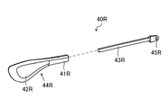
図5は、テンプルパッド40Rの分解拡大図である。テンプルパッド40Rは、塑性変形可能な金属製の芯材43Rと、根元部分41Rおよびそれに続く先端部分42Rが一体部材として形成された合成樹脂(好ましくはやや軟質の合成樹脂)製のパッド本体44Rと、を備えている。芯材43Rの一端は上下方向にわずかに膨らんでネジ穴45Rが設けられている。パッド本体44Rの根元部分41Rの側面には芯材43Rを差し込むための開口部があり、その開口部からパッド本体44Rの全長方向に向けて芯材43Rにパッド本体44Rを被せることができるようになっている。芯材43Rにパッド本体44Rの奥まで被せた状態において、ネジ穴45Rを含む芯材43Rの一端が露出するようになっている。
FIG. 5 is an exploded enlarged view of the
芯材43Rの寸法は、長さがおよそ40mm、厚みがおよそ1mm、上下方向の幅がおよそ1mm、パッド本体44Rから露出する部分の上下方向の幅がおよそ3mm、当該部分の長さがおよそ5mm、ネジ穴45Rの直径がおよそ1mmである。パッド本体44Rの寸法は、全長がおよそ44mm、厚みがおよそ3mm、根元部分41Rの上下方向の幅がおよそ4mm、先端部分42Rの上下方向の最大幅がおよそ12mm、パッド本体44Rの最先端部から上下方向が最大幅の部分までの長さはおよそ10mmである。なお、これら寸法は一例であって、本発明はこれらに限定されない。
The
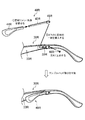
図6は、テンプルパッド40Rの取り付けを説明する図である。同図に示すように、(1)芯材43Rにパッド本体44Rを被せ、(2)ネジ穴45Rが設けられた芯材43Rの一端をポケット35Rに差し込み、(3)孔39Rにネジ46Rを通してネジ止めすることで、テンプルパッド40Rをテンプル30Rの内側の所定位置に固定することができる。
FIG. 6 is a diagram illustrating attachment of the
ネジ46Rの長さはおよそ3mmであり、直径はおよそ1mmである。なお、これら寸法は一例であって、本発明はこれに限定されない。
The
テンプルパッド40Rを交換する場合、ネジ46Rを外してポケット35Rからテンプルパッド40Rを引き抜いて新たなテンプルパッド40Rと交換すればよい。あるいは、ポケット35Rに芯材43Rをネジ止めしたままでパッド本体44Rのみを交換することもできる。
When replacing the
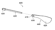
図7は、テンプルパッド40Rからパッド本体44Rを引き抜いた状態を示す図である。テンプルパッド40Rからパッド本体44Rを引き抜くと芯材43Rが現れる。芯材43Rは、ネジ穴45Rが設けられた一端から他端にかけてテンプル30Rの内側面33Rから徐々に逸れるようにテンプル30Rの延在方向に沿って延びている。同図に示したように芯材43Rを露出させた状態で新たなパッド本体44Rを芯材43Rに被せればよい。
FIG. 7 is a diagram showing a state where the
なお、テンプルパッド40Lは上述のテンプルパッド40Rと形状が鏡面対称になるだけであるため、詳細な説明を省略する。
The
≪効果≫
本実施形態に係る眼鏡100は、左側のテンプル30L、モダン32L、ポケット35L、および右側のテンプル30R、モダン32R、ポケット35Rがそれぞれ一体部材として形成されており、特に、テンプル30L,30Rの外側面34L,34Rは、それぞれ、ヒンジ50L,50Rに接続される部分からモダン32L,32Rの末端に至るまで段差のない滑らかな曲面に形成されている。さらに、ヨロイ23L,23Rの上下方向の幅および厚みがそれぞれテンプル30L,30Rの上下方向の幅および厚みに合わされている。これによりテンプル30L,30Rを広げた状態において、フロント20から左右のテンプル30L,30R、さらに左右のモダン32L,32Rに至るまでの部分が一体的に続いてすっきりとした印象を与えるデザインとなっている。
<<Effect>>
In the
また、眼鏡100を装着する際にモダン32L,32Rの末端部分の内側の立体曲面形状部分が側頭部に接触しながら耳の上部から後ろにかけて移動し、眼鏡100を装着した状態においてモダン32L,32Rの末端部分が耳の後ろを左右両側から適度な力で挟み込んで眼鏡100の後端を頭部にしっかりとホールドすることができる。
In addition, when wearing the
また、テンプルパッド40L,40Rの根元を、それぞれ、テンプル30L,30Rの略直線部分31L,31Rの後端付近に固定し、そこからテンプル30L,30Rの内側面33L,33Rから徐々に逸れるように略直線部分31L,31Rに沿ってフロント20側に延びるようにテンプルパッド40L,40Rを配置したことで、眼鏡100を装着する際にテンプルパッド40L,40Rの先端部分42L,42Rが側頭部に引っかからずにスムースに眼鏡100を装着することができる。
Further, the roots of the
また、金属製の芯材を有するテンプルパッド40L,40Rが適度な弾力性を呈することで、眼鏡100を装着した状態においてテンプルパッド40L,40Rの先端部分42L,42Rが左右からこめかみを適度な力で挟み込んで、鼻パッドなしでもフロント20がずり落ちないようにしっかりとサポートすることができる。
In addition, since the
さらに、眼鏡100を装着していない状態においてテンプルパッド40L,40Rに指で力を加えるなどして、テンプルパッド40L,40Rの先端部分42L,42Rを眼鏡100の装着者の頭部形状に合うようにより内側またはより外側に寄せることもできる。
Furthermore, by applying a force to the
また、テンプルパッド40L,40Rの芯材43L,43Rをテンプル30L,30Rに固定したままパッド本体が外せるため、テンプルパッド40L,40Rの交換が容易である。
Further, since the pad body can be removed while the
さらに特筆すべきは、本実施形態に係る眼鏡100は、側面視でテンプルパッド40L,40Rのほとんどがテンプル30L,30Rに隠れて見えなくなっていることである。図3は眼鏡100の左側面図であるが、テンプル30Lからテンプルパッド40Lの先端部分42Lの下部がわずかに覗く程度である。
It should be further noted that in the
このように、本実施形態に係る眼鏡100は、こめかみとの接触部分の面積が比較的大きいテンプルパッド40L,40Rを採用しつつ、眼鏡100の装着時にテンプルパッド40L,40Rが目立たないようになっている。これにより鼻パッドなしで安定的に装着可能であるとともに装着時に支持構造を目立たなくするといった所期の目的が達成されている。
As described above, the
≪変形例≫
上記の眼鏡100は次のように適宜変形してもよい。例えば、左側のテンプル30L、モダン32L、ポケット35L、および右側のテンプル30R、モダン32R、ポケット35Rをそれぞれ別のパーツで形成して繋ぎ合わせるようにしてもよい。
≪Modification≫
The
ポケット35L,35Rを設けずに、テンプル30L,30Rの内側面33L,33Rにテンプルパッド40L,40Rを直接固定するようにしてもよい。
The
フレーム21L,21Rをツーポイントフレームやナイロールフレームにしてもよい。
The
ヒンジ50L,50Rをなくしてもよい。
The
テンプル30L,30Rの上下方向の幅を少し広くする、あるいは、テンプルパッド40L,40Rの先端部分42L,42Rの上下方向の幅を少し狭くする、またはその両方を行って、側面視でテンプルパッド40L,40Rの全体がテンプル30L,30Rに隠れて見えないようにしてもよい。
The width of the
≪髪の毛の挟み込み対策≫
上記実施形態に係る眼鏡100では、テンプルパッド40L,40Rがテンプル30L,30Rの後端部分からフロント20側に向けてテンプル30L,30Rの内側面33L,33Rから徐々に逸れるように配置されているため、眼鏡100を装着する際に髪の毛がテンプル30L,30Rとテンプルパッド40L,40Rとの隙間に入り込んでテンプルパッド40L,40Rの根元部分41L,41Rに引っ掛かって抜けなくなってしまうおそれがある。そこで、テンプルパッド40L,40Rを逆向きに配置してもよい。すなわち、テンプルパッド40L,40Rの根元をヒンジ50L,50R付近に固定して、そこから後方に向けて先端部分42L,42Rがテンプル30L,30Rの内側面33L,33Rから徐々に逸れるようにテンプル30L,30Rの延在方向に沿ってテンプルパッド40L,40Rを取り付けてもよい。
<<Countermeasures for pinching hair>>
In the
あるいは、テンプルパッド40L,40Rの根元部分41Rに凸部を設けてもよい。図8は、変形例に係るテンプルパッド40Rの斜視図であり、図5を裏から見た図である。当該変形例に係るテンプルパッド40Rにおいて、パッド本体44Rの根元部分41Rのテンプル30R(図略)に面する側に、根元部分41Rにおけるテンプルパッド40Rとテンプル30Rとの隙間を埋める程度にわずかに突起した凸部47Rが形成されている。一例として、凸部47Rは、パッド本体44Rの根元部分41Rの表面からおよそ1mm突起して、パッド本体44Rの根元部分41Rの側面(芯材43Rを差し込むための開口部端)からおよそ2mmの幅で先端部分42Rに向けておよそ6mm延びている。図9は、図8のテンプルパッド40Rをテンプル30Rに取り付けたときの取り付け部分の拡大図である。凸部47Rによってテンプルパッド40Rの根元部分41Rにおけるテンプルパッド40Rとテンプル30Rとの隙間が埋められることにより、眼鏡100を装着する際に髪の毛がテンプル30Rとテンプルパッド40Rとの隙間に入り込んでもテンプルパッド40Rの根元部分41Rに引っ掛からずにすっと抜けることができる。
Alternatively, a convex portion may be provided on the
凸部47Rの形状は図5に示したものに限られず、断面形状が三角形やかまぼこ型であってもよい。また、凸部47Rは、テンプルパッド40Rの根元部分41Rの側面から延在していなくてもよく、根元部分41Rの側面から6mm程度の位置において突起するように設けてもよい。あるいは、テンプルパッド40Rに凸部47Rを設けずに、テンプル30Rの内側面33R(図7参照)に凸部を設けるようにしてもよい。なお、テンプルパッド40Lはテンプルパッド40Rと形状が鏡面対称になるだけであるため、テンプルパッド40Lの変形例についての詳細な説明を省略する。
The shape of the
≪フロントのずり落ち対策≫
眼鏡100には鼻パッドがないため、装着時にモダン32L,32Rが装着者の後頭部(耳の後ろ)をしっかり保持できていないとテンプルパッド40L,40Rの先端部分42L,42Rを支点にしてフロント20がずり落ちてしまうおそれがある。そこで、後頭部をよりしっかり保持できるようにモダン32L,32Rの厚みをより厚くしてもよい。図10は、通常のモダンと変形例に係るモダンとの比較図である。通常のモダンと同様に変形例に係るモダンも先端付近が肉厚に形成されて内側に膨らんでいるが、その最厚部の厚みは通常のモダンのおよそ3倍の7mm程度にされている。このようにモダンの先端付近の厚みを厚くすることで眼鏡100を装着したときにモダン32L,32Rが装着者の後頭部をしっかり保持することができ、フロント20のずり落ちを防いで眼鏡100の装着感を向上させることができる。
≪Prevention of front slippage≫
Since the
以上のように、本発明における技術の例示として、実施の形態を説明した。そのために、添付図面および詳細な説明を提供した。 As described above, the embodiment has been described as an example of the technique of the present invention. To that end, the accompanying drawings and detailed description are provided.
したがって、添付図面および詳細な説明に記載された構成要素の中には、課題解決のために必須な構成要素だけでなく、上記技術を例示するために、課題解決のためには必須でない構成要素も含まれ得る。そのため、それらの必須ではない構成要素が添付図面や詳細な説明に記載されていることをもって、直ちに、それらの必須ではない構成要素が必須であるとの認定をするべきではない。 Therefore, among the components described in the accompanying drawings and the detailed description, not only the components essential for solving the problem but also the components not essential for solving the problem in order to exemplify the above technology Can also be included. Therefore, it should not be immediately recognized that the non-essential components are essential by the fact that the non-essential components are described in the accompanying drawings and the detailed description.
また、上述の実施の形態は、本発明における技術を例示するためのものであるから、特許請求の範囲またはその均等の範囲において種々の変更、置き換え、付加、省略などを行うことができる。 Further, since the above-described embodiment is for exemplifying the technique of the present invention, various changes, replacements, additions, omissions, etc. can be made within the scope of the claims or the scope equivalent thereto.
100…眼鏡、30L,30R…テンプル、32L,32R…モダン、35L,35R…ポケット、40L,40R…テンプルパッド、41L,41R…根元部分、42L,42R…先端部分、43R…芯材、44R…パッド本体、47R…凸部 100... Glasses, 30L, 30R... Temple, 32L, 32R... Modern, 35L, 35R... Pocket, 40L, 40R... Temple pad, 41L, 41R... Root part, 42L, 42R... Tip part, 43R... Core material, 44R... Pad body, 47R... convex portion
Claims (6)
上下方向に幅広のテンプルと、
根元が前記テンプルの内側の所定位置に固定され、そこから先端にかけて前記テンプルの内側面から徐々に逸れるように前記テンプルの延在方向に沿って延びるテンプルパッドと、を備え、
前記テンプルパッドは、根元部分が細く、かつ、前記眼鏡を装着した際に装着者のこめかみに接する先端部分が下方に緩やかに膨らむ肉厚形状に形成されており、
側面視で前記テンプルパッドの全体またはほとんどが前記テンプルに隠れて見えないようになっており、
前記テンプルパッドは、根元が前記テンプルの後方寄りの所定位置に固定され、そこから前方に延びており、
前記テンプルパッドの根元部分の前記テンプルに面する側に当該根元部分における前記テンプルパッドと前記テンプルとの隙間を埋める程度に突起した凸部が形成されている
ことを特徴とする眼鏡。 Glasses,
A wide temple in the vertical direction,
A root is fixed at a predetermined position inside the temple, and a temple pad extending along the extending direction of the temple so as to gradually deviate from the inner side surface of the temple from there to a tip, and,
The temple pad has a thin root portion, and the tip portion in contact with the temples of the wearer when the eyeglasses are worn is formed in a thick shape that gently swells downward,
All or most of the temple pad is hidden from view by the temple in a side view ,
The temple pad, the root is fixed at a predetermined position near the rear of the temple, and extends forward from there,
The spectacles , wherein a convex portion is formed on a side of the root portion of the temple pad facing the temple so as to fill a gap between the temple pad and the temple in the root portion .
前記テンプルパッドの根元部分の先端が前記ポケットに差し込まれて前記テンプルパッドが前記テンプルに固定されている
ことを特徴とする請求項1に記載の眼鏡。 The temple has a pocket opening on the inner side surface in the extending direction of the temple,
The spectacles according to claim 1 , wherein a tip of a root portion of the temple pad is inserted into the pocket to fix the temple pad to the temple.
ことを特徴とする請求項2に記載の眼鏡。 The spectacles according to claim 2 , wherein the temple, the pocket, and the modern are formed as an integral member.
ことを特徴とする請求項3に記載の眼鏡。 The spectacles according to claim 3 , wherein the vicinity of the tip of the modern bulge inward at a thickness of the thickest part of about 7 mm.
塑性変形可能な金属製の芯材と、
前記芯材の一端が露出するように前記芯材に被せられ、前記根元部分およびそれに続く前記先端部分が一体部材として形成された合成樹脂製のパッド本体と、を有しており、
前記芯材が、前記パッド本体から露出した一端が前記テンプルの内側の前記所定位置に固定され、そこから他端にかけて前記テンプルの内側面から徐々に逸れるように前記テンプルの延在方向に沿って延びている
ことを特徴とする請求項1ないし4のいずれかに記載の眼鏡。 The temple pad is
A plastically deformable metal core,
The core material is covered with the core material so that one end of the core material is exposed, and the root portion and the tip portion subsequent thereto have a synthetic resin pad body formed as an integral member,
One end of the core member, which is exposed from the pad body, is fixed to the predetermined position inside the temple, and along the extending direction of the temple so as to gradually deviate from the inner surface of the temple toward the other end. The spectacles according to any one of claims 1 to 4, which are extended.
ことを特徴とする請求項1ないし4のいずれかに記載の眼鏡。 The spectacles according to any one of claims 1 to 4 , wherein the temple pad is detachably fixed to the temple.
Priority Applications (6)
| Application Number | Priority Date | Filing Date | Title |
|---|---|---|---|
| PCT/JP2019/046701 WO2020116333A1 (en) | 2018-12-04 | 2019-11-29 | Eyeglasses |
| CN201980029238.8A CN112074776B (en) | 2018-12-04 | 2019-11-29 | Glasses |
| KR1020207029670A KR102289399B1 (en) | 2018-12-04 | 2019-11-29 | glasses |
| EP19892234.6A EP3767373B1 (en) | 2018-12-04 | 2019-11-29 | Eyeglasses |
| US17/051,418 US11281021B2 (en) | 2018-12-04 | 2019-11-29 | Eyeglasses |
| TW108144067A TWI723661B (en) | 2018-12-04 | 2019-12-03 | Glasses |
Applications Claiming Priority (2)
| Application Number | Priority Date | Filing Date | Title |
|---|---|---|---|
| JP2018226945 | 2018-12-04 | ||
| JP2018226945 | 2018-12-04 |
Publications (3)
| Publication Number | Publication Date |
|---|---|
| JP2020095243A JP2020095243A (en) | 2020-06-18 |
| JP2020095243A5 JP2020095243A5 (en) | 2020-08-13 |
| JP6749712B2 true JP6749712B2 (en) | 2020-09-02 |
Family
ID=71086159
Family Applications (1)
| Application Number | Title | Priority Date | Filing Date |
|---|---|---|---|
| JP2019134270A Active JP6749712B2 (en) | 2018-12-04 | 2019-07-22 | glasses |
Country Status (5)
| Country | Link |
|---|---|
| EP (1) | EP3767373B1 (en) |
| JP (1) | JP6749712B2 (en) |
| KR (1) | KR102289399B1 (en) |
| CN (1) | CN112074776B (en) |
| TW (1) | TWI723661B (en) |
Families Citing this family (3)
| Publication number | Priority date | Publication date | Assignee | Title |
|---|---|---|---|---|
| US20210247625A1 (en) * | 2019-08-19 | 2021-08-12 | Troy Adam Devore | Eyewear design with temple retention features |
| JP7313044B2 (en) * | 2019-09-06 | 2023-07-24 | 山本光学株式会社 | glasses |
| JP2022191931A (en) | 2021-06-16 | 2022-12-28 | ライン工業株式会社 | Spectacles |
Family Cites Families (13)
| Publication number | Priority date | Publication date | Assignee | Title |
|---|---|---|---|---|
| US1719957A (en) * | 1926-04-28 | 1929-07-09 | Burton M Arrick | Spectacle template |
| JPS5414551U (en) * | 1977-07-04 | 1979-01-30 | ||
| JPS565058Y2 (en) * | 1977-09-01 | 1981-02-04 | ||
| JP2001201721A (en) | 2000-01-17 | 2001-07-27 | Katsuki Optical Co Ltd | Spectacle frame |
| JP2003121800A (en) | 2001-10-19 | 2003-04-23 | Keite Optica:Kk | Temple of spectacle frame |
| US8168701B2 (en) | 2008-04-24 | 2012-05-01 | W. R. Grace & Co.-Conn. | Concrete or mortar admixture composition |
| KR20110099939A (en) | 2010-03-03 | 2011-09-09 | 숭실대학교산학협력단 | Liquid crystal device and its method for homeotropic alignment by using liquid crystal and photocurable monomer composite system through light irradiation |
| TWM404392U (en) * | 2010-12-30 | 2011-05-21 | All Logic Internat Co Ltd | Temple of eyeglasses with auxiliary pad holder |
| CN103246079A (en) * | 2012-02-03 | 2013-08-14 | 浩捷光学有限公司 | Glasses |
| JP3198964U (en) | 2015-05-19 | 2015-07-30 | 株式会社シャルマン | glasses |
| CN205899173U (en) * | 2016-06-28 | 2017-01-18 | 亮风台(上海)信息科技有限公司 | Glasses are dressed to intelligence |
| CN106773140B (en) * | 2016-11-24 | 2019-03-12 | 厦门大学 | Glasses automated assembly machine |
| JP3214365U (en) | 2017-10-24 | 2018-01-11 | 国立大学法人福井大学 | Medical equipment |
-
2019
- 2019-07-22 JP JP2019134270A patent/JP6749712B2/en active Active
- 2019-11-29 EP EP19892234.6A patent/EP3767373B1/en active Active
- 2019-11-29 KR KR1020207029670A patent/KR102289399B1/en active IP Right Grant
- 2019-11-29 CN CN201980029238.8A patent/CN112074776B/en active Active
- 2019-12-03 TW TW108144067A patent/TWI723661B/en active
Also Published As
| Publication number | Publication date |
|---|---|
| EP3767373C0 (en) | 2023-10-18 |
| TWI723661B (en) | 2021-04-01 |
| EP3767373A4 (en) | 2021-06-30 |
| EP3767373A1 (en) | 2021-01-20 |
| EP3767373B1 (en) | 2023-10-18 |
| JP2020095243A (en) | 2020-06-18 |
| TW202024726A (en) | 2020-07-01 |
| CN112074776A (en) | 2020-12-11 |
| CN112074776B (en) | 2022-12-09 |
| KR20200125741A (en) | 2020-11-04 |
| KR102289399B1 (en) | 2021-08-13 |
Similar Documents
| Publication | Publication Date | Title |
|---|---|---|
| JP6749712B2 (en) | glasses | |
| WO2020116333A1 (en) | Eyeglasses | |
| US9535261B2 (en) | Eyeglass temple having an auxiliary cushion frame | |
| JP2015038608A (en) | Spectacle without nose pad | |
| KR20140039091A (en) | Nose pad and eyewear | |
| JP5697196B2 (en) | Nose padless glasses | |
| US20140132911A1 (en) | Temple for eyeglass frame, and method for producing temple | |
| JP5690907B1 (en) | Glasses front frame with inner frame | |
| JP6407793B2 (en) | Head-mounted display device | |
| TWM597882U (en) | Eyeglasses with function of assembling and disassembling of lens | |
| JP5961776B2 (en) | glasses | |
| WO2020255470A1 (en) | Glasses | |
| JP7301099B2 (en) | nose pads and eyewear | |
| KR102565302B1 (en) | Nose bridge for eyeglass frames with seating power and excellent tightness | |
| JP6848007B2 (en) | Nose pad and eyewear | |
| JP5038873B2 (en) | Eyeglass frame and eyeglass frame armor | |
| JP3880927B2 (en) | Glasses nose pad | |
| JP3107987U (en) | Eyeglass frames | |
| JP2009008927A (en) | Protective eyeglasses | |
| JP2023106681A (en) | Lens and glasses | |
| JP2006106273A (en) | Nose pad | |
| JP3688247B2 (en) | Free size glasses | |
| JP3133220U (en) | Additional eyeglass frame | |
| JP5390350B2 (en) | Glasses temple and glasses | |
| KR20200058875A (en) | The glass frame with anti-exit features |
Legal Events
| Date | Code | Title | Description |
|---|---|---|---|
| A521 | Request for written amendment filed |
Free format text: JAPANESE INTERMEDIATE CODE: A523 Effective date: 20191122 |
|
| A521 | Request for written amendment filed |
Free format text: JAPANESE INTERMEDIATE CODE: A523 Effective date: 20200629 |
|
| A621 | Written request for application examination |
Free format text: JAPANESE INTERMEDIATE CODE: A621 Effective date: 20200629 |
|
| A871 | Explanation of circumstances concerning accelerated examination |
Free format text: JAPANESE INTERMEDIATE CODE: A871 Effective date: 20200629 |
|
| A975 | Report on accelerated examination |
Free format text: JAPANESE INTERMEDIATE CODE: A971005 Effective date: 20200706 |
|
| A131 | Notification of reasons for refusal |
Free format text: JAPANESE INTERMEDIATE CODE: A131 Effective date: 20200714 |
|
| TRDD | Decision of grant or rejection written | ||
| A01 | Written decision to grant a patent or to grant a registration (utility model) |
Free format text: JAPANESE INTERMEDIATE CODE: A01 Effective date: 20200805 |
|
| A61 | First payment of annual fees (during grant procedure) |
Free format text: JAPANESE INTERMEDIATE CODE: A61 Effective date: 20200806 |
|
| R150 | Certificate of patent or registration of utility model |
Ref document number: 6749712 Country of ref document: JP Free format text: JAPANESE INTERMEDIATE CODE: R150 |
|
| R250 | Receipt of annual fees |
Free format text: JAPANESE INTERMEDIATE CODE: R250 |