JP6747460B2 - Control device for internal combustion engine - Google Patents
Control device for internal combustion engine Download PDFInfo
- Publication number
- JP6747460B2 JP6747460B2 JP2018013054A JP2018013054A JP6747460B2 JP 6747460 B2 JP6747460 B2 JP 6747460B2 JP 2018013054 A JP2018013054 A JP 2018013054A JP 2018013054 A JP2018013054 A JP 2018013054A JP 6747460 B2 JP6747460 B2 JP 6747460B2
- Authority
- JP
- Japan
- Prior art keywords
- injection
- fuel
- fuel pressure
- internal combustion
- combustion engine
- Prior art date
- Legal status (The legal status is an assumption and is not a legal conclusion. Google has not performed a legal analysis and makes no representation as to the accuracy of the status listed.)
- Active
Links
Images


Classifications
-
- F—MECHANICAL ENGINEERING; LIGHTING; HEATING; WEAPONS; BLASTING
- F02—COMBUSTION ENGINES; HOT-GAS OR COMBUSTION-PRODUCT ENGINE PLANTS
- F02D—CONTROLLING COMBUSTION ENGINES
- F02D43/00—Conjoint electrical control of two or more functions, e.g. ignition, fuel-air mixture, recirculation, supercharging or exhaust-gas treatment
-
- F—MECHANICAL ENGINEERING; LIGHTING; HEATING; WEAPONS; BLASTING
- F02—COMBUSTION ENGINES; HOT-GAS OR COMBUSTION-PRODUCT ENGINE PLANTS
- F02D—CONTROLLING COMBUSTION ENGINES
- F02D41/00—Electrical control of supply of combustible mixture or its constituents
- F02D41/30—Controlling fuel injection
- F02D41/38—Controlling fuel injection of the high pressure type
- F02D41/40—Controlling fuel injection of the high pressure type with means for controlling injection timing or duration
- F02D41/402—Multiple injections
-
- F—MECHANICAL ENGINEERING; LIGHTING; HEATING; WEAPONS; BLASTING
- F02—COMBUSTION ENGINES; HOT-GAS OR COMBUSTION-PRODUCT ENGINE PLANTS
- F02D—CONTROLLING COMBUSTION ENGINES
- F02D37/00—Non-electrical conjoint control of two or more functions of engines, not otherwise provided for
- F02D37/02—Non-electrical conjoint control of two or more functions of engines, not otherwise provided for one of the functions being ignition
-
- F—MECHANICAL ENGINEERING; LIGHTING; HEATING; WEAPONS; BLASTING
- F02—COMBUSTION ENGINES; HOT-GAS OR COMBUSTION-PRODUCT ENGINE PLANTS
- F02D—CONTROLLING COMBUSTION ENGINES
- F02D41/00—Electrical control of supply of combustible mixture or its constituents
- F02D41/009—Electrical control of supply of combustible mixture or its constituents using means for generating position or synchronisation signals
-
- F—MECHANICAL ENGINEERING; LIGHTING; HEATING; WEAPONS; BLASTING
- F02—COMBUSTION ENGINES; HOT-GAS OR COMBUSTION-PRODUCT ENGINE PLANTS
- F02P—IGNITION, OTHER THAN COMPRESSION IGNITION, FOR INTERNAL-COMBUSTION ENGINES; TESTING OF IGNITION TIMING IN COMPRESSION-IGNITION ENGINES
- F02P5/00—Advancing or retarding ignition; Control therefor
- F02P5/04—Advancing or retarding ignition; Control therefor automatically, as a function of the working conditions of the engine or vehicle or of the atmospheric conditions
- F02P5/045—Advancing or retarding ignition; Control therefor automatically, as a function of the working conditions of the engine or vehicle or of the atmospheric conditions combined with electronic control of other engine functions, e.g. fuel injection
-
- F—MECHANICAL ENGINEERING; LIGHTING; HEATING; WEAPONS; BLASTING
- F02—COMBUSTION ENGINES; HOT-GAS OR COMBUSTION-PRODUCT ENGINE PLANTS
- F02P—IGNITION, OTHER THAN COMPRESSION IGNITION, FOR INTERNAL-COMBUSTION ENGINES; TESTING OF IGNITION TIMING IN COMPRESSION-IGNITION ENGINES
- F02P5/00—Advancing or retarding ignition; Control therefor
- F02P5/04—Advancing or retarding ignition; Control therefor automatically, as a function of the working conditions of the engine or vehicle or of the atmospheric conditions
- F02P5/05—Advancing or retarding ignition; Control therefor automatically, as a function of the working conditions of the engine or vehicle or of the atmospheric conditions using mechanical means
- F02P5/06—Advancing or retarding ignition; Control therefor automatically, as a function of the working conditions of the engine or vehicle or of the atmospheric conditions using mechanical means dependent on engine speed
-
- F—MECHANICAL ENGINEERING; LIGHTING; HEATING; WEAPONS; BLASTING
- F02—COMBUSTION ENGINES; HOT-GAS OR COMBUSTION-PRODUCT ENGINE PLANTS
- F02P—IGNITION, OTHER THAN COMPRESSION IGNITION, FOR INTERNAL-COMBUSTION ENGINES; TESTING OF IGNITION TIMING IN COMPRESSION-IGNITION ENGINES
- F02P5/00—Advancing or retarding ignition; Control therefor
- F02P5/04—Advancing or retarding ignition; Control therefor automatically, as a function of the working conditions of the engine or vehicle or of the atmospheric conditions
- F02P5/145—Advancing or retarding ignition; Control therefor automatically, as a function of the working conditions of the engine or vehicle or of the atmospheric conditions using electrical means
- F02P5/15—Digital data processing
- F02P5/1502—Digital data processing using one central computing unit
-
- F—MECHANICAL ENGINEERING; LIGHTING; HEATING; WEAPONS; BLASTING
- F02—COMBUSTION ENGINES; HOT-GAS OR COMBUSTION-PRODUCT ENGINE PLANTS
- F02D—CONTROLLING COMBUSTION ENGINES
- F02D41/00—Electrical control of supply of combustible mixture or its constituents
- F02D41/30—Controlling fuel injection
- F02D41/38—Controlling fuel injection of the high pressure type
- F02D2041/389—Controlling fuel injection of the high pressure type for injecting directly into the cylinder
-
- F—MECHANICAL ENGINEERING; LIGHTING; HEATING; WEAPONS; BLASTING
- F02—COMBUSTION ENGINES; HOT-GAS OR COMBUSTION-PRODUCT ENGINE PLANTS
- F02D—CONTROLLING COMBUSTION ENGINES
- F02D2200/00—Input parameters for engine control
- F02D2200/02—Input parameters for engine control the parameters being related to the engine
- F02D2200/06—Fuel or fuel supply system parameters
- F02D2200/0602—Fuel pressure
-
- F—MECHANICAL ENGINEERING; LIGHTING; HEATING; WEAPONS; BLASTING
- F02—COMBUSTION ENGINES; HOT-GAS OR COMBUSTION-PRODUCT ENGINE PLANTS
- F02D—CONTROLLING COMBUSTION ENGINES
- F02D41/00—Electrical control of supply of combustible mixture or its constituents
- F02D41/02—Circuit arrangements for generating control signals
- F02D41/18—Circuit arrangements for generating control signals by measuring intake air flow
-
- F—MECHANICAL ENGINEERING; LIGHTING; HEATING; WEAPONS; BLASTING
- F02—COMBUSTION ENGINES; HOT-GAS OR COMBUSTION-PRODUCT ENGINE PLANTS
- F02D—CONTROLLING COMBUSTION ENGINES
- F02D41/00—Electrical control of supply of combustible mixture or its constituents
- F02D41/30—Controlling fuel injection
- F02D41/38—Controlling fuel injection of the high pressure type
- F02D41/40—Controlling fuel injection of the high pressure type with means for controlling injection timing or duration
- F02D41/402—Multiple injections
- F02D41/403—Multiple injections with pilot injections
-
- Y—GENERAL TAGGING OF NEW TECHNOLOGICAL DEVELOPMENTS; GENERAL TAGGING OF CROSS-SECTIONAL TECHNOLOGIES SPANNING OVER SEVERAL SECTIONS OF THE IPC; TECHNICAL SUBJECTS COVERED BY FORMER USPC CROSS-REFERENCE ART COLLECTIONS [XRACs] AND DIGESTS
- Y02—TECHNOLOGIES OR APPLICATIONS FOR MITIGATION OR ADAPTATION AGAINST CLIMATE CHANGE
- Y02T—CLIMATE CHANGE MITIGATION TECHNOLOGIES RELATED TO TRANSPORTATION
- Y02T10/00—Road transport of goods or passengers
- Y02T10/10—Internal combustion engine [ICE] based vehicles
- Y02T10/40—Engine management systems
Description
筒内噴射方式の内燃機関に適用される内燃機関の制御装置に関する。 The present invention relates to a control device for an internal combustion engine which is applied to a cylinder injection type internal combustion engine.
内燃機関の燃焼室へ燃料を直接噴射する筒内噴射方式の内燃機関が知られている。また、特許文献1には、筒内噴射方式の内燃機関において、燃料噴射弁に1燃焼サイクル中に噴射される総噴射量を複数に分割して噴射させるものが開示されている。特許文献1に開示された内燃機関では、最終回の分割噴射が圧縮行程後半に実施されることで、燃焼室内において点火プラグの点火位置周辺を局部的にリッチ状態とし、内燃機関の燃焼性を向上させている。
A cylinder injection type internal combustion engine in which fuel is directly injected into a combustion chamber of the internal combustion engine is known.
特許文献1では、各分割噴射の噴射時期は、出力軸の回転角度を示すクランク角により定められている。また、点火プラグの点火時期も、クランク角により定められている。このため、最終回の分割噴射での噴射時期から点火時期までの間隔が、クランク角により規定されることとなり、出力軸の回転速度の影響を受ける。そのため、出力軸の回転速度に応じて、最終回の分割噴射において燃料が噴射されてから点火時期までの時間が異なる場合がある。その結果、出力軸の回転速度の変化に伴い、燃焼室内の点火位置周囲に形成される燃料噴霧の拡散状態が変化し、内燃機関の燃焼性を低下させるおそれがある。
In
本発明は上記課題に鑑みたものであり、内燃機関において燃焼状態を適正化することができる内燃機関の制御装置を提供することを目的とする。 The present invention has been made in view of the above problems, and an object of the present invention is to provide a control device for an internal combustion engine that can optimize the combustion state of the internal combustion engine.
上記課題を解決するために本発明に係る制御装置は、燃焼室内へ燃料を直接噴射する燃料噴射弁と、前記燃焼室内に点火火花を生じさせる点火プラグと、を備える内燃機関に適用され、1燃焼サイクル中に前記燃料噴射弁による複数回の分割噴射を実施させるとともに、前記分割噴射のうち、最終回の分割噴射を圧縮行程後半で実施させる噴射制御部を備える。また、制御装置は、前記最終回の分割噴射での噴射時期から前記点火プラグの点火時期までの時間間隔を、燃圧が同一となる領域において一定時間に設定する時間設定部と、前記時間間隔と前記内燃機関の出力軸の回転速度とに基づいて、前記最終回の分割噴射での噴射時期を示すクランク角位置を設定する噴射時期設定部と、を備える。 In order to solve the above problems, the control device according to the present invention is applied to an internal combustion engine that includes a fuel injection valve that directly injects fuel into a combustion chamber and an ignition plug that produces an ignition spark in the combustion chamber. An injection control unit is provided which causes the fuel injection valve to perform a plurality of divided injections during a combustion cycle and also performs the final divided injection among the divided injections in the latter half of the compression stroke. In addition, the control device, the time interval from the injection timing in the last split injection to the ignition timing of the spark plug, a time setting unit that sets a constant time in the region where the fuel pressure is the same, and the time interval. An injection timing setting unit that sets a crank angle position indicating an injection timing in the final divided injection based on the rotation speed of the output shaft of the internal combustion engine.
燃焼室内において、点火位置の周囲に形成される燃料噴霧の拡散状態は、同一の燃圧領域であれば、最終回の分割噴射が実施されてからの時間に応じて定まる。そこで、本発明では、最終回の分割噴射での噴射時期から点火プラグの点火時期までの時間間隔が、燃圧が同一となる領域において一定時間に設定される。そして、時間間隔と内燃機関の出力軸の回転速度とに基づいて、最終回の分割噴射での噴射時期を示すクランク角位置が設定される。この場合、同一の燃圧領域であれば、最終回の分割噴射が実施されてから点火時期までが同じ時間に設定されることで、最終回の分割噴射により形成された燃料噴霧を点火位置の周囲に適正に拡散させることができ、内燃機関の燃焼状態を適正化することができる。 In the combustion chamber, the diffusion state of the fuel spray formed around the ignition position is determined according to the time after the last split injection is performed, if the fuel pressure is in the same fuel pressure region. Therefore, in the present invention, the time interval from the injection timing of the final split injection to the ignition timing of the spark plug is set to a constant time in the region where the fuel pressure is the same. Then, based on the time interval and the rotation speed of the output shaft of the internal combustion engine, the crank angle position indicating the injection timing in the final split injection is set. In this case, in the same fuel pressure region, the fuel spray formed by the final split injection is set around the ignition position by setting the same time from the final split injection to the ignition timing. Therefore, the combustion state of the internal combustion engine can be optimized.
以下、本実施形態について図面を参照しつつ説明する。本実施形態は、内燃機関である筒内噴射式の多気筒4サイクルガソリンエンジンを対象にエンジン制御システムを構築するものとしている。 Hereinafter, the present embodiment will be described with reference to the drawings. In the present embodiment, an engine control system is constructed for a cylinder injection type multi-cylinder 4-cycle gasoline engine which is an internal combustion engine.
図1に示すエンジン制御システムは、エンジン10と、制御装置としてのECU40とを備えている。エンジン10は、4つの気筒を備える4気筒エンジンである。なお、図1では、1つの気筒のみを図示し、他の気筒については図示を省略している。
The engine control system shown in FIG. 1 includes an
エンジン10は、気筒が設けられたエンジン本体20を備えている。このうち、燃焼室21は、気筒において、シリンダ内壁とピストン22の上面(頂部)とにより区画形成される空間である。
The
エンジン本体20の上部に位置するシリンダヘッドには、燃焼室21毎に点火プラグ29が設けられている。点火プラグ29には、図示しない点火コイル等を通じて、所望とする点火時期において点火パルスが印加される。この点火パルスの印加により、各点火プラグ29の対向電極間に点火火花が発生する。
A
エンジン本体20には燃焼室21毎に燃料噴射弁としてのインジェクタ30が設けられている。インジェクタ30は、シリンダヘッドにおいて、点火プラグ29の近傍に配置されており、かつ燃焼室21の上側から下側に向けて燃料を燃焼室21内に直接噴射するセンター噴射式のインジェクタである。インジェクタ30は、電磁駆動式であり、不図示の駆動回路を通じて、所望とする噴射時期において駆動パルスが印加される。この駆動パルスの印加により、インジェクタ30が開弁状態となり、燃料が噴射される。
The
インジェクタ30は、燃料配管24を介して燃料タンク25に接続されている。燃料タンク25内の燃料は、低圧ポンプ26により汲み上げられた後、高圧ポンプ27により加圧される。高圧ポンプ27の駆動を制御することで、燃料に加圧される圧力を可変設定することが可能となる。高圧ポンプ27により高圧化された高圧燃料は、デリバリパイプ28に圧送され、デリバリパイプ28から各気筒のインジェクタ30に供給される。また、デリバリパイプ28には、インジェクタ30に供給される燃料の圧力を燃圧Pfとして検出する燃圧センサ35が設けられている。
The
エンジン本体20の吸気ポート及び排気ポートには、それぞれ図示しないカム軸の回転に応じて開閉動作する吸気弁18及び排気弁19が設けられている。吸気弁18の開動作により吸気通路11を流れる吸入空気が燃焼室21内に導入される。また、排気弁19の開動作により燃焼後の排気が排気通路33に排出される。吸気弁18及び排気弁19それぞれには、吸気弁18及び排気弁19の開閉タイミングを可変とする可変動弁機構18A,19Aが設けられている。可変動弁機構18A,19Aは、エンジン10のクランク軸と吸排気の各カム軸との相対回転位相を調整するものであり、所定の基準位置に対して進角側及び遅角側への位相調整が可能となっている。
The intake port and the exhaust port of the
エンジン本体20には、エンジン10の運転時に所定クランク角ごとに矩形状のクランク角信号を出力するクランク角度センサ34が設けられている。ECU40は、クランク角信号に基づいて、出力軸23の回転速度を回転速度NEとして検出することができる。
The
吸気通路11には、吸入空気量を検出するためのエアフロメータ12が設けられている。エアフロメータ12の下流側には、DCモータ等のスロットルアクチュエータ13によって開度調節されるスロットルバルブ14が設けられている。スロットルバルブ14の下流側にはサージタンク15が設けられている。また、サージタンク15には、エンジン10の各気筒に空気を導入する吸気マニホールド17が接続されており、吸気マニホールド17において各気筒の吸気ポートに接続されている。
The
排気通路33には、排ガス中のCO,HC,NOx等を浄化するための三元触媒等の触媒31が設けられている。
The
上述した各種センサの出力は、ECU40に入力される。ECU40は、CPU、ROM、RAM等よりなるマイクロコンピュータを備え、ROMに記憶された各種の制御プログラムを実行することで、エンジン運転状態に応じたインジェクタ30の燃料噴射量の制御、点火プラグ29の点火時期の可変設定、及び高圧ポンプ27による燃料圧力の可変制御を行う。本実施形態では、ECU40が点火時期設定部に相当する。
The outputs of the various sensors described above are input to the
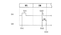
図2は、1燃焼サイクルにおける、インジェクタ30の駆動パルスGA及び点火プラグ29の点火パルスGBの推移を示すタイミングチャートである。
FIG. 2 is a timing chart showing transitions of the drive pulse GA of the
ECU40は、1燃焼サイクルで燃焼室21内に噴射される総噴射量を、複数回に分割してインジェクタ30に噴射させる分割噴射制御を実施する。具体的には、分割噴射制御では、吸気行程において、1又は2回の駆動パルスGA1によりインジェクタ30での分割噴射が行われた後、圧縮行程後半において、駆動パルスGA2によりインジェクタ30での最終回の分割噴射が行われる。ここで、噴射時期CA1は、吸気行程内での分割噴射が開始されるクランク角位置を示し、本実施形態では、駆動パルスGA1が立ち上がるタイミングである。噴射時期CA2は、圧縮行程後半での分割噴射が開始されるクランク角位置を示し、本実施形態では、駆動パルスGA2が立ち上がるタイミングである。また、点火時期CA3は、点火プラグ29が点火するクランク角位置を示し、本実施形態では、点火パルスGBが立ち上がるタイミングである。なお、クランク角位置は、出力軸23の回転位置を示し、本実施形態では、この回転位置により定められる時期としての意味をも有する。以下、最終回の分割噴射での噴射時期CA2を、単に最終噴射時期CA2とも称する。本実施形態では、ECU40が噴射制御部に相当する。
The
上記各噴射時期CA1,CA2で噴射された燃料は、インジェクタ30の噴孔から噴射された後、燃料噴霧となって点火プラグ29の電極の周囲又はその付近に到達し、点火プラグ29からの点火火花により着火する。
The fuel injected at each of the injection timings CA1 and CA2 is injected from the injection hole of the
図3は、最終回の分割噴射により形成される燃料噴霧FSの拡散状態を示している。分割噴射のうち、最終回の分割噴射が圧縮行程後半に実施されることで、最終回の分割噴射で形成された燃料噴霧FSにより、点火プラグ29の点火直前において、点火プラグ29の電極29Aの周辺又は付近が局部的に筒内の混合気よりもリッチ状態となる。そして、点火時期CA3において、燃料噴霧に着火した火は、燃焼室21内を燃え広がり、混合気の燃焼が促進される。燃焼室21内において点火プラグ29の電極周囲又は付近を点火位置とも称する。
FIG. 3 shows a diffusion state of the fuel spray FS formed by the final split injection. Of the split injections, the final split injection is performed in the latter half of the compression stroke, so that the fuel spray FS formed in the final split injection causes the electrode 29A of the
点火位置周囲又は付近に適正な拡散状態での燃料噴霧を形成することができれば、エンジン10の燃焼性を高めることができる。ここで、燃料噴霧の拡散状態は、最終噴射時期CA2から点火時期CA3までの間隔を示すインターバルの長さに応じて変化する。具体的には、インターバルが長いほど、燃料噴霧における燃焼室21の上側から下側に向けた拡散状態が大きくなり、インターバルが短いほど、燃料噴霧における燃焼室21の上側から下側に向けた拡散状態が小さくなる。
If it is possible to form the fuel spray in an appropriate diffusion state around or near the ignition position, the combustibility of the
各分割噴射を1燃焼サイクル中の所望の時期に実施するため、各噴射時期CA1,CA2は、出力軸23の回転角度位置を示すクランク角位置により定められている。また、点火プラグ29の点火時期CA3も、クランク角位置により定められる。このため、最終噴射時期CA2から点火時期CA3までの間隔を示すインターバルが、クランク角位置により規定されることとなり、出力軸23の回転速度NEの影響を受ける。インターバルがクランク角位置では同じ間隔で規定されていても、回転速度NEが大きくなるほど、インターバルの時間が短くなる。また、回転速度NEが小さくなるほど、インターバルの時間が長くなる。そのため、回転速度NEに応じて、点火位置周囲に形成される燃料噴霧の拡散状態が変化し、燃焼室21内の燃焼性が低下するおそれがある。例えば、回転速度が1000rpmから2000rpmへ2倍となることで、インターバルは、半分の時間となる。
In order to carry out each divided injection at a desired timing in one combustion cycle, the respective injection timings CA1 and CA2 are determined by the crank angle position indicating the rotational angle position of the
本発明者は、燃焼室21内において、点火位置の周囲に形成される燃料噴霧の拡散状態は、同一の燃圧領域であれば、最終噴射時期CA2からの時間に応じて定まることを着目した。また、燃料の圧力が一定であれば、時間経過に伴う燃料噴霧の拡散状態が同じであることに着目した。そこで、ECU40は、最終噴射時期CA2から点火時期CA3までのインターバルを、燃圧Pfが同一となる領域において一定時間に設定する。そして、ECU40は、設定した時間間隔と出力軸23の回転速度NEとに基づいて、最終噴射時期CA2をクランク角位置により設定することとした。
The present inventor has noticed that the diffusion state of the fuel spray formed around the ignition position in the
次に、本実施形態での分割噴射制御の手順を、図4を用いて説明する。図4に示す処理は、ECU40により所定周期で繰り返し実施される。
Next, the procedure of the split injection control in this embodiment will be described with reference to FIG. The process shown in FIG. 4 is repeatedly executed by the
ステップS11では、1燃焼サイクル中の総噴射量FTを設定する。例えば、エンジン10の運転状態に応じて、総噴射量FTを設定する。
In step S11, the total injection amount FT in one combustion cycle is set. For example, the total injection amount FT is set according to the operating state of the
ステップS12では、燃圧センサ35の検出値から現在の燃圧Pfを取得する。 In step S12, the current fuel pressure Pf is acquired from the detection value of the fuel pressure sensor 35.
燃料噴霧の微粒化は、燃圧Pfが高いほど促進されるため、燃圧Pfが低い場合に圧縮行程後半に分割噴射が行われることで、燃料噴霧の気化が起こりにくくなるおそれがある。そこで、本実施形態では、燃圧Pfが燃圧判定値SH1よりも小さな値である場合は、圧縮行程後半での分割噴射を実施しないこととしている。 The atomization of the fuel spray is promoted as the fuel pressure Pf is higher. Therefore, when the fuel pressure Pf is low, the divided injection is performed in the latter half of the compression stroke, which may make the vaporization of the fuel spray less likely to occur. Therefore, in the present embodiment, when the fuel pressure Pf is a value smaller than the fuel pressure determination value SH1, split injection in the latter half of the compression stroke is not performed.
ステップS13では、ステップS12で取得した燃圧Pfが燃圧判定値SH1よりも小さな値であるか否かを判定する。燃圧判定値SH1は、例えば、エンジン10において、圧縮行程後半での分割噴射を実施した場合に、排気中の未燃ガスやPMが所定値以上となる燃圧Pfとして定められている。燃圧Pfが燃圧判定値SH1よりも小さいと判定すると、ステップS21に進む。ステップS13が判定部に相当する。
In step S13, it is determined whether the fuel pressure Pf acquired in step S12 is a value smaller than the fuel pressure determination value SH1. The fuel pressure determination value SH1 is defined as, for example, the fuel pressure Pf at which unburned gas or PM in the exhaust gas becomes a predetermined value or more when the
ステップS21では、最終噴射時期CA2を圧縮行程後半に設定しないように、インジェクタ30による分割噴射を実施させる。本実施形態では、2回の分割噴射の噴射時期CA1,CA2を、圧縮行程後半よりも前に設定することで、インジェクタ30による分割噴射を実施させる。なお、ステップS21において、吸気行程において、インジェクタ30に総噴射量FTを1回で噴射させてもよい。
In step S21, the divided injection by the
一方、燃圧Pfが燃圧判定値SH1以上であると判定すると、ステップS14に進む。ステップS14では、ステップS11で設定した総噴射量FTに基づいて、各分割噴射により噴射される分割噴射量を設定する。本実施形態では、燃料噴霧の分散性を同じ条件に揃えるために、最終回の分割噴射による噴射量を、回転速度NEによらず同じ値としている。また、最終回の分割噴射での分割噴射量を、初回の分割噴射での分割噴射量よりも小さな値に設定している。 On the other hand, when it is determined that the fuel pressure Pf is equal to or higher than the fuel pressure determination value SH1, the process proceeds to step S14. In step S14, the split injection amount injected by each split injection is set based on the total injection amount FT set in step S11. In the present embodiment, in order to make the dispersibility of the fuel spray uniform under the same conditions, the injection amount of the final divided injection is set to the same value regardless of the rotation speed NE. Further, the divided injection amount in the final divided injection is set to a value smaller than the divided injection amount in the first divided injection.
ステップS15では、点火プラグ29の点火が開始される点火時期CA3を取得する。
In step S15, the ignition timing CA3 at which the ignition of the
ステップS16では、ステップS12で取得した燃圧Pfに基づいて、最終噴射時期CA2から点火時期CA3までのインターバルを、実時間で定めた時間間隔TWとして設定する。時間間隔TWは、エンジン10の燃焼性を適正とする燃料噴霧が形成される時間に応じてその値が定められている。より具体的には、インジェクタ30の燃料噴射により形成された燃料噴霧が点火プラグ29の電極29Aの位置又はその付近に到達するのに要する時間を示している。ステップS16が時間設定部に相当する。
In step S16, the interval from the final injection timing CA2 to the ignition timing CA3 is set as the time interval TW determined in real time based on the fuel pressure Pf acquired in step S12. The value of the time interval TW is set according to the time when the fuel spray that makes the combustibility of the
図5は、所定の燃圧領域における時間間隔TWの定め方を説明する図である。図5では、横軸を実時間で定めたインターバルとし、縦軸を燃焼安定指数COV(Coefficient Of Variation)とした図である。燃焼安定指数COVとは、エンジン10の燃焼において、最も安定性の悪い失火から最も安定性の良い完全燃焼までの度合を示す指数であり、その値が小さいほど燃焼の安定性が高いことを示している。
FIG. 5 is a diagram illustrating how to set the time interval TW in a predetermined fuel pressure region. In FIG. 5, the horizontal axis is an interval determined in real time, and the vertical axis is a combustion stability index COV (Coefficient Of Variation). The combustion stability index COV is an index indicating the degree of misfire from the worst stability to the most stable complete combustion in the combustion of the
図5では、時間間隔がW1からW4の範囲において、燃焼安定指数COVが目標値以下となり、時間間隔がW1よりも小さい範囲、及びW4よりも大きい範囲において、燃焼安定指数COVが目標値よりも大きくなっている。すなわち、時間間隔TWをW1からW4の範囲内の時間間隔で設定すれば、燃焼安定指数COVを目標値以下にでき、燃焼安定性を高めることができる。本実施形態では、外乱等を考慮して、時間間隔TWを、W1からW4までの範囲よりも狭いW2からW3までの範囲において定めている。 In FIG. 5, the combustion stability index COV is less than or equal to the target value in the time interval W1 to W4, and the combustion stability index COV is less than the target value in the range where the time interval is smaller than W1 and larger than W4. It's getting bigger. That is, if the time interval TW is set at a time interval within the range of W1 to W4, the combustion stability index COV can be made equal to or less than the target value, and the combustion stability can be improved. In the present embodiment, the time interval TW is set in the range from W2 to W3, which is narrower than the range from W1 to W4, in consideration of disturbance and the like.
また、燃圧Pfの変化により、インジェクタ30により噴射される燃料の初速が変化し、燃料噴霧が点火位置周辺まで拡散する時間に影響を与える。具体的には、燃圧Pfが高くなるほど、燃料噴霧が点火位置周辺まで拡散するのに要する時間が短くなる。そこで、本実施形態では、ステップS12で取得した燃圧Pfが属する燃圧領域APが大きくなるほど、時間間隔TWを小さく設定している。図6は、燃圧領域APと、時間間隔TWとの関係を説明する図である。
Further, the change in the fuel pressure Pf changes the initial velocity of the fuel injected by the
図6では、一例として、エンジン10が燃圧Pfを可変することで取り得る燃圧範囲を5つの燃圧領域AP1,AP2,AP3,AP4,AP5に分割している。本実施形態では、各燃圧領域AP1〜AP5は、均等に定められている。図6において、燃圧領域AP1〜AP5の値が大きくなるほど、各燃圧領域AP1〜AP5に対応づけられた時間間隔TWが小さくなっている。例えば、燃圧領域AP1〜AP5と時間間隔TWとの関係を定めるマップを保持しておく。そして、ステップS12で取得した燃圧Pfが属する燃圧領域AP1〜AP5に対応する時間間隔TWをマップから参照すればよい。
In FIG. 6, as an example, the fuel pressure range that the
図4に戻り、ステップS17では、現在の出力軸23の回転速度NEを取得する。
Returning to FIG. 4, in step S17, the current rotational speed NE of the
ステップS18では、ステップS17で取得した回転速度NEに基づいて、ステップS16で設定した時間間隔TWで示される時間間隔を、クランク角により規定した角度換算値CWに変換する。角度換算値CWは、出力軸23が、現在の回転速度NEで時間間隔TWだけ回転する場合のクランク角の変化量を示す値である。本実施形態では、角度換算値CWが角度間隔に相当する。
In step S18, the time interval indicated by the time interval TW set in step S16 is converted into the angle conversion value CW defined by the crank angle based on the rotation speed NE acquired in step S17. The angle conversion value CW is a value that indicates the amount of change in the crank angle when the
本実施形態では、最終噴射時期CA2を圧縮行程後半に設定するため、所定の回転速度NEにおける角度換算値CWの最大値は、圧縮行程前半と圧縮行程後半との境界を示すクランク角位置から点火時期CA3までのクランク角位置までの変化量以下にすることが望ましい。 In the present embodiment, since the final injection timing CA2 is set in the latter half of the compression stroke, the maximum value of the angle conversion value CW at the predetermined rotation speed NE is ignition from the crank angle position indicating the boundary between the first half of the compression stroke and the second half of the compression stroke. It is desirable that the amount of change to the crank angle position up to the timing CA3 is equal to or less than the change amount.
ステップS19では、ステップS18で取得した角度換算値CWに基づいて、最終噴射時期CA2を設定する。本実施形態では、図7に示すように、点火時期CA3から角度換算値CWだけ戻ったクランク角位置を最終噴射時期CA2として設定する。そのため、最終噴射時期CA2から点火時期CA3までのインターバルが、角度換算値CWが示す一定の時間(=TW)に定められる。ステップS18及びステップS19が、噴射時期設定部に相当する。 In step S19, the final injection timing CA2 is set based on the angle conversion value CW acquired in step S18. In the present embodiment, as shown in FIG. 7, the crank angle position returned from the ignition timing CA3 by the angle conversion value CW is set as the final injection timing CA2. Therefore, the interval from the final injection timing CA2 to the ignition timing CA3 is set to a fixed time (=TW) indicated by the angle conversion value CW. Step S18 and step S19 correspond to the injection timing setting unit.
図4に戻り、ステップS20では、分割噴射を実施させる。このとき、吸気行程において、初回の分割噴射の噴射時期CA1に応じて、駆動パルスGA1がインジェクタ30に印加される。その後、圧縮構成後半において、最終噴射時期CA2に応じて、駆動パルスGA2がインジェクタ30に印加される。
Returning to FIG. 4, in step S20, split injection is performed. At this time, in the intake stroke, the drive pulse GA1 is applied to the
以上説明した本実施形態では、以下の効果を奏する。 The present embodiment described above has the following effects.
・ECU40は、最終噴射時期CA2から点火時期CA3までの時間間隔を、燃圧Pfが同一となる領域において一定の時間間隔TWに設定する。そして、設定した時間間隔TWと出力軸23の回転速度NEとに基づいて、最終噴射時期CA2を示すクランク角位置を設定する。この場合、同一の燃圧領域APであれば、最終噴射時期CA2から点火時期CA3までが同一時間に設定されることで、最終回の分割噴射により形成された燃料噴霧を点火位置の周囲に適正に拡散させることができる。その結果、エンジン10の燃焼状態を適正化することができる。
The
・ECU40は、時間間隔TWを、エンジン10の出力軸23の回転速度NEに基づいて、クランク角で規定される角度換算値CWに変換し、点火時期CA3と、角度換算値CWとにより最終噴射時期CA2を設定する。この場合、出力軸23の回転速度NEを考慮して、インターバルを設定でき、エンジン10の燃焼状態をいっそう適正化することができる。
The
・ECU40は、燃圧Pfが属する燃圧領域APに基づいて、時間間隔TWを設定する。具体的には、燃圧Pfが属する燃圧領域APが大きくなるほど、時間間隔TWを小さくする。この場合、燃圧の変化に起因する燃料噴霧の拡散性を考慮した時間間隔によりインターバルを設定でき、エンジン10の燃焼状態をいっそう適正化することができる。
The
・ECU40は、インターバルを同一の時間間隔に設定することに加えて、最終回の分割噴射での燃料噴射量を一定とする。この場合、運転条件によらず、燃料噴霧の分散性が同じ条件となることで、エンジン10の燃焼状態をいっそう適正化することができる。
The
・インジェクタ30は、点火プラグ29の近傍に配置されたセンター噴射式である。また、ECU40は、インジェクタ30から噴射された燃料が点火プラグ29の電極29Aの位置又はその付近に到達するまでの時間を、時間間隔TWとして設定する。この場合、インジェクタ30により噴射された燃料噴霧が、直ちに点火位置周辺に到達することで、燃焼室21内の気流の影響を低減することができ、エンジン10の燃焼状態をいっそう適正化することができる。
The
・ECU40は、燃圧Pfが所定の燃圧判定値SH1以上と判定した場合に、圧縮行程後半での分割噴射が実施される。一方、燃圧Pfが燃圧判定値SH1よりも小さいと判定した場合に、圧縮行程後半での分割噴射を実施しない。この場合、エンジン10において、気化していない燃料の増加による排気の悪化を抑制することができる。
When the
(その他の実施形態)
・点火プラグ29は、センター噴射式のものに代えて、燃料を燃焼室21の横方向から噴射するサイド噴射式のものであってもよい。この場合においても、ECU40は、インジェクタ30から噴射された燃料が点火プラグ29の電極29Aの位置又はその付近に到達するまでの時間を、時間間隔TWとして設定すればよい。
(Other embodiments)
The
・最終回の分割噴射量を、回転速度NEによらず一定とすることに代えて、最終回の分割噴射量を、回転速度NEに応じて可変としてもよい。 The final divided injection amount may be variable according to the rotational speed NE, instead of being constant regardless of the rotational speed NE.
・エンジン10が取り得る燃圧範囲を均等に分割することに代えて、燃圧範囲を不均等に分割することで燃圧領域を定めてもよい。
The fuel pressure range may be defined by unevenly dividing the fuel pressure range instead of dividing the fuel pressure range that the
10…エンジン、21…燃焼室、29…点火プラグ、30…インジェクタ、40…ECU。 10... Engine, 21... Combustion chamber, 29... Spark plug, 30... Injector, 40... ECU.
Claims (5)
前記最終回の分割噴射での噴射時期から前記点火プラグの点火時期までの時間間隔を、燃圧が同一となる領域において、一定時間に設定する時間設定部と、
前記時間設定部により設定された前記時間間隔と、前記内燃機関の出力軸の回転速度とに基づいて、前記最終回の分割噴射での噴射時期を示すクランク角位置を設定する噴射時期設定部と、を備え、
前記噴射制御部は、前記最終回の分割噴射による噴射量を、前記回転速度によらず同じ噴射量に設定する内燃機関の制御装置。 It is applied to an internal combustion engine (10) including a fuel injection valve (30) for directly injecting fuel into a combustion chamber (21) and a spark plug (29) for producing an ignition spark in the combustion chamber, and one combustion cycle. A control device (40) for an internal combustion engine, comprising: an injection control unit that causes a plurality of divided injections by the fuel injection valve to be performed therein and the final divided injection among the divided injections in the latter half of the compression stroke. hand,
A time setting unit that sets a time interval from the injection timing in the final divided injection to the ignition timing of the spark plug in a region where the fuel pressure is the same, to a constant time,
An injection timing setting unit that sets a crank angle position indicating an injection timing in the final divided injection based on the time interval set by the time setting unit and the rotation speed of the output shaft of the internal combustion engine. , equipped with a,
The control device for an internal combustion engine, wherein the injection control unit sets the injection amount of the final divided injection to the same injection amount regardless of the rotation speed .
前記噴射時期設定部は、
前記内燃機関の出力軸の回転速度に基づいて、前記時間設定部により設定された前記時間間隔を、クランク角で規定される角度間隔に変換し、
前記点火プラグの点火時期と、前記角度間隔とにより前記最終回の分割噴射での噴射時期を設定する請求項1に記載の内燃機関の制御装置。 An ignition timing setting unit for setting the ignition timing,
The injection timing setting unit,
Based on the rotation speed of the output shaft of the internal combustion engine, the time interval set by the time setting unit is converted into an angular interval defined by a crank angle,
The control device for an internal combustion engine according to claim 1, wherein the injection timing in the final divided injection is set based on the ignition timing of the spark plug and the angular interval.
前記時間設定部は、前記燃圧が属する燃圧領域に基づいて、前記時間間隔を設定する請求項1又は2に記載の内燃機関の制御装置。 The fuel pressure is set to be variable,
The control device for an internal combustion engine according to claim 1, wherein the time setting unit sets the time interval based on a fuel pressure region to which the fuel pressure belongs.
前記時間設定部は、前記燃料噴射弁から噴射された燃料が前記点火プラグの電極の位置又はその付近に到達するまでの時間を、前記時間間隔として設定する請求項1〜3のいずれか一項に記載の内燃機関の制御装置。 The fuel injection valve is a center injection type disposed near the spark plug,
The time setting unit, the time until the fuel injected from the fuel injection valve reaches the position or near the electrodes of the spark plug, any one of claim 1 to 3 is set as the time interval A control device for an internal combustion engine according to item 1.
前記噴射制御部は、前記燃圧が前記燃圧判定値以上と判定された場合に、前記燃料噴射弁に前記圧縮行程後半での前記分割噴射を実施させ、前記燃圧が前記燃圧判定値よりも小さいと判定された場合に、前記燃料噴射弁に前記圧縮行程後半での前記分割噴射を実施させない請求項1〜4のいずれか一項に記載の内燃機関の制御装置。 A determination unit for determining whether or not the fuel pressure is lower than a predetermined fuel pressure determination value,
When the fuel pressure is determined to be equal to or higher than the fuel pressure determination value, the injection control unit causes the fuel injection valve to perform the split injection in the latter half of the compression stroke, and the fuel pressure is lower than the fuel pressure determination value. If it is determined, the control apparatus for an internal combustion engine according to any one of the split injection does not implement the claims 1-4 in the latter half of the compression stroke to the fuel injection valve.
Priority Applications (4)
| Application Number | Priority Date | Filing Date | Title |
|---|---|---|---|
| JP2018013054A JP6747460B2 (en) | 2018-01-29 | 2018-01-29 | Control device for internal combustion engine |
| DE112019000562.6T DE112019000562T5 (en) | 2018-01-29 | 2019-01-21 | Control device of a machine with internal combustion |
| PCT/JP2019/001636 WO2019146541A1 (en) | 2018-01-29 | 2019-01-21 | Internal combustion engine control device |
| US16/928,141 US11421623B2 (en) | 2018-01-29 | 2020-07-14 | Internal combustion engine control device |
Applications Claiming Priority (1)
| Application Number | Priority Date | Filing Date | Title |
|---|---|---|---|
| JP2018013054A JP6747460B2 (en) | 2018-01-29 | 2018-01-29 | Control device for internal combustion engine |
Publications (3)
| Publication Number | Publication Date |
|---|---|
| JP2019132148A JP2019132148A (en) | 2019-08-08 |
| JP2019132148A5 JP2019132148A5 (en) | 2020-01-23 |
| JP6747460B2 true JP6747460B2 (en) | 2020-08-26 |
Family
ID=67394941
Family Applications (1)
| Application Number | Title | Priority Date | Filing Date |
|---|---|---|---|
| JP2018013054A Active JP6747460B2 (en) | 2018-01-29 | 2018-01-29 | Control device for internal combustion engine |
Country Status (4)
| Country | Link |
|---|---|
| US (1) | US11421623B2 (en) |
| JP (1) | JP6747460B2 (en) |
| DE (1) | DE112019000562T5 (en) |
| WO (1) | WO2019146541A1 (en) |
Family Cites Families (7)
| Publication number | Priority date | Publication date | Assignee | Title |
|---|---|---|---|---|
| JP2002038993A (en) * | 2000-07-24 | 2002-02-06 | Hitachi Ltd | Control device for cylinder injection engine |
| JP2002054486A (en) * | 2000-08-10 | 2002-02-20 | Honda Motor Co Ltd | Control device for internal combustion engine |
| JP3968331B2 (en) * | 2003-08-14 | 2007-08-29 | 株式会社日立製作所 | Fuel injection control device and method for in-cylinder internal combustion engine |
| JP2006169976A (en) * | 2004-12-13 | 2006-06-29 | Toyota Motor Corp | Fuel injector of internal combustion engine |
| JP4492399B2 (en) * | 2005-03-16 | 2010-06-30 | 日産自動車株式会社 | In-cylinder direct injection spark ignition internal combustion engine control device and control method |
| JP5543843B2 (en) * | 2010-05-20 | 2014-07-09 | 本田技研工業株式会社 | Control device for internal combustion engine |
| JP2015151977A (en) | 2014-02-18 | 2015-08-24 | 日立オートモティブシステムズ株式会社 | Control device for direct fuel injection type internal combustion engine |
-
2018
- 2018-01-29 JP JP2018013054A patent/JP6747460B2/en active Active
-
2019
- 2019-01-21 DE DE112019000562.6T patent/DE112019000562T5/en active Pending
- 2019-01-21 WO PCT/JP2019/001636 patent/WO2019146541A1/en active Application Filing
-
2020
- 2020-07-14 US US16/928,141 patent/US11421623B2/en active Active
Also Published As
| Publication number | Publication date |
|---|---|
| WO2019146541A1 (en) | 2019-08-01 |
| US20200340422A1 (en) | 2020-10-29 |
| US11421623B2 (en) | 2022-08-23 |
| DE112019000562T5 (en) | 2020-10-08 |
| JP2019132148A (en) | 2019-08-08 |
Similar Documents
| Publication | Publication Date | Title |
|---|---|---|
| JP6784214B2 (en) | Internal combustion engine control device | |
| JP3692930B2 (en) | Combustion control device for direct-injection spark-ignition internal combustion engine | |
| JP6376289B2 (en) | Internal combustion engine control device and internal combustion engine control method | |
| JP4085900B2 (en) | Fuel injection control device for in-cylinder direct injection spark ignition engine | |
| JP4089109B2 (en) | Ignition control device for internal combustion engine | |
| JP3893909B2 (en) | Control device for direct-injection spark-ignition internal combustion engine | |
| US20180010548A1 (en) | Control device for internal combustion engine | |
| JP4492399B2 (en) | In-cylinder direct injection spark ignition internal combustion engine control device and control method | |
| JP4631725B2 (en) | In-cylinder direct injection spark ignition internal combustion engine controller | |
| JP6747460B2 (en) | Control device for internal combustion engine | |
| JPH11173180A (en) | Cylinder injection type spark ignition engine | |
| JP5282636B2 (en) | Control device for internal combustion engine | |
| JP4379670B2 (en) | Fuel property determination device for internal combustion engine | |
| JP2017166493A (en) | Control device for direct injection engine | |
| JP4055292B2 (en) | Direct injection spark ignition internal combustion engine fuel injection control device | |
| JP2006177179A (en) | Control device for cylinder direct injection type spark ignition internal combustion engine | |
| US9903303B2 (en) | Control apparatus for internal combustion engine | |
| JP2018178891A (en) | Control device of internal combustion engine | |
| JP2015004343A (en) | Control device of direct injection engine | |
| JP5195383B2 (en) | In-cylinder direct injection spark ignition internal combustion engine | |
| JP3572372B2 (en) | Fuel injection control device for direct injection spark ignition engine | |
| JP4407442B2 (en) | Fuel pressure control device for in-cylinder injection engine | |
| JPH10331682A (en) | Combustion stabilizing device of direct injection type spark ignition engine | |
| JP2000337235A (en) | Ignition control device of internal combustion engine | |
| JP4389831B2 (en) | In-cylinder direct injection spark ignition internal combustion engine controller |
Legal Events
| Date | Code | Title | Description |
|---|---|---|---|
| A521 | Request for written amendment filed |
Free format text: JAPANESE INTERMEDIATE CODE: A523 Effective date: 20191204 |
|
| A621 | Written request for application examination |
Free format text: JAPANESE INTERMEDIATE CODE: A621 Effective date: 20191204 |
|
| TRDD | Decision of grant or rejection written | ||
| A01 | Written decision to grant a patent or to grant a registration (utility model) |
Free format text: JAPANESE INTERMEDIATE CODE: A01 Effective date: 20200707 |
|
| A61 | First payment of annual fees (during grant procedure) |
Free format text: JAPANESE INTERMEDIATE CODE: A61 Effective date: 20200720 |
|
| R151 | Written notification of patent or utility model registration |
Ref document number: 6747460 Country of ref document: JP Free format text: JAPANESE INTERMEDIATE CODE: R151 |
|
| R250 | Receipt of annual fees |
Free format text: JAPANESE INTERMEDIATE CODE: R250 |