JP6745557B2 - Gas discharge nozzle and carrier - Google Patents
Gas discharge nozzle and carrier Download PDFInfo
- Publication number
- JP6745557B2 JP6745557B2 JP2020038518A JP2020038518A JP6745557B2 JP 6745557 B2 JP6745557 B2 JP 6745557B2 JP 2020038518 A JP2020038518 A JP 2020038518A JP 2020038518 A JP2020038518 A JP 2020038518A JP 6745557 B2 JP6745557 B2 JP 6745557B2
- Authority
- JP
- Japan
- Prior art keywords
- laminar flow
- flow passage
- gas
- discharge nozzle
- gas discharge
- Prior art date
- Legal status (The legal status is an assumption and is not a legal conclusion. Google has not performed a legal analysis and makes no representation as to the accuracy of the status listed.)
- Active
Links
Images


Landscapes
- Nozzles (AREA)
Description
この発明は、高圧気体を吐出する気体吐出用ノズルであって所定の吐出方向に沿って層流気体を形成する気体吐出用ノズル、及びこの気体吐出用ノズルから吐出された層流気体によって被搬送物の搬送性能を向上させる搬送装置に関する。 The present invention relates to a gas discharge nozzle for discharging a high-pressure gas, which forms a laminar flow gas along a predetermined discharge direction, and a laminar flow gas discharged from the gas discharge nozzle. The present invention relates to a transfer device that improves the transfer performance of objects.
搬送中の被搬送物の表面に付着した液滴を除去する手法として、被搬送物の表面に圧縮空気等の高圧気体を吐出する気体吐出用ノズルが用いられる。例えば、エアナイフと呼ばれる気体吐出用ノズルから搬送中の円筒状の容器に高圧の空気を吹き付け、容器の所定の領域から水分を除去するものがある(例えば、特許文献1参照。)。 As a method for removing droplets adhering to the surface of the transported object being transported, a gas ejection nozzle for ejecting high-pressure gas such as compressed air onto the surface of the transported object is used. For example, there is a device in which high-pressure air is blown from a gas discharge nozzle called an air knife to a cylindrical container being conveyed to remove water from a predetermined region of the container (for example, refer to Patent Document 1).
エアナイフから搬送中の容器に向けて吐出される高圧の空気は、容器の姿勢に影響を与える可能性がある。このため、エアナイフは、容器に対して所定の角度を維持するように位置決めされる。 The high-pressure air discharged from the air knife toward the container being conveyed may affect the posture of the container. Therefore, the air knife is positioned so as to maintain a predetermined angle with respect to the container.
しかし、従来の気体吐出用ノズルは、被搬送物から液滴を除去することのみを目的としており、搬送装置の搬送性能を考慮したものではなかった。このため、従来の気体吐出用ノズルは、被搬送物の搬送に寄与できないばかりか、エアナイフから被搬送物に向けて吐出される高圧気体が搬送の負荷となって搬送性能を低下させる可能性がある。 However, the conventional gas discharge nozzle has only the purpose of removing droplets from the object to be conveyed, and does not consider the conveying performance of the conveying device. For this reason, the conventional gas discharge nozzles cannot not only contribute to the conveyance of the conveyed object, but also the high-pressure gas ejected from the air knife toward the conveyed object may cause a conveyance load and deteriorate the conveyance performance. is there.
この発明の目的は、高圧気体の吐出方向に沿って層流気体を形成することで、搬送装置の搬送性能の向上に寄与できる気体吐出用ノズル及び搬送装置を提供することにある。 An object of the present invention is to provide a gas discharge nozzle and a carrier device that can contribute to improving the carrier performance of the carrier device by forming a laminar gas along the discharge direction of high-pressure gas.
この発明の気体吐出用ノズルは、上面における一端側の所定範囲を除いて長手方向に沿って形成された層流通過面と、前記一端側の所定範囲で下面側に向かって傾斜した傾斜面と、外部から高圧空気が流入する流入口を有する空間部であって前記傾斜面の形範囲内で上面に開放した空間部と、を有し、前記空間部内の高圧気体を前記層流通過面に向けて吐出するスリットが形成される本体と、前記空間部の前記上面側を被覆するカバーと、を備え、前記スリットは、前記本体内における前記空間部から前記層流通過面に至る間に形成された第1面であって前記層流通過面に向けて吐出した高圧気体が前記層流通過面に沿う前記長手方向の層流となる所定の層流形成角度で前記層流通過面に連続する第1面と、前記カバーの下面であって前記第1面に平行で前記第1面よりも前記本体の外側に位置する第2面と、の間隙に前記長手方向に傾斜して交差するように形成されるとともに、前記層流通過面側で前記長手方向に直交する方向に沿って開口し、前記カバーにおける前記第2面より外側の部分は、前記層流通過面の延長線より前記第1面側に位置し、前記流入口は、前記本体の前記下面から前記空間部に連通する。 The gas discharge nozzle according to the present invention includes a laminar flow passage surface formed along the longitudinal direction excluding a predetermined range on the one end side of the upper surface, and an inclined surface inclined toward the lower surface side in the predetermined range on the one end side. A space portion having an inflow port through which high-pressure air flows from the outside, the space portion being open to the upper surface within the shape range of the inclined surface, and the high-pressure gas in the space portion to the laminar flow passage surface. A main body in which a slit for discharging toward is formed, and a cover that covers the upper surface side of the space portion, and the slit is formed between the space portion and the laminar flow passage surface in the main body. The first surface, which is the formed first surface, is continuous to the laminar flow passage surface at a predetermined laminar flow formation angle at which the high-pressure gas discharged toward the laminar flow passage surface becomes a laminar flow in the longitudinal direction along the laminar flow passage surface. And a second surface, which is a lower surface of the cover and which is parallel to the first surface and is located outside the main body with respect to the first surface, intersects with a slope in the longitudinal direction. And the opening on the side of the laminar flow passage surface along the direction orthogonal to the longitudinal direction, and the portion of the cover outside the second surface is the extension line of the laminar flow passage surface. Located on the first surface side, the inflow port communicates with the space from the lower surface of the main body.
スリットから吐出された高圧気体は、層流通過面の表面に沿って層流を形成し、層流に接する部分に位置する外気を層流内に二次気体として誘引する。スリットから吐出された高圧気体は誘引した二次気体によって増幅され、スリットから吐出方向の下流側に向かって吐出量よりも多量の気体による気流が層流通過面の表面に沿って形成される。本体における第2面より外側の部分が第1面に連続する層流通過面の延長線よりも第1面側に位置しているため、スリットを層流通過面の表面側に突出しないように配置することができる。 The high-pressure gas discharged from the slit forms a laminar flow along the surface of the laminar flow passage surface, and attracts outside air located in a portion in contact with the laminar flow into the laminar flow as a secondary gas. The high-pressure gas discharged from the slit is amplified by the attracted secondary gas, and a gas flow of a larger amount than the discharge amount is formed along the surface of the laminar flow surface from the slit toward the downstream side in the discharge direction. Since the portion of the main body outside the second surface is located on the first surface side with respect to the extension line of the laminar flow passage surface continuous with the first surface, the slit should not project to the surface side of the laminar flow passage surface. Can be placed.
この発明の搬送装置は、上述の気体吐出用ノズルと気体供給装置とを備えている。気体供給装置は、気体吐出用ノズルに高圧気体を供給する。気体吐出用ノズルの表面は、被搬送物の搬送方向に沿って配置される。 A carrier device of the present invention includes the above-described gas discharge nozzle and gas supply device. The gas supply device supplies high pressure gas to the gas discharge nozzle. The surface of the gas discharge nozzle is arranged along the transport direction of the transported object.
気体吐出用ノズルのスリットから吐出された高圧気体が層流通過面に沿って形成する層流方向は、被搬送物の搬送方向と平行になる。高圧気体の層流方向を被搬送物の搬送方向に一致させると、被搬送物の搬送方向に沿って形成される多量の気体による気流が、被搬送物の搬送に寄与する。高圧気体の層流方向を被搬送物の搬送方向とは逆方向にすると、搬送中の被搬送物に回転力を供給できる。スリットが層流通過面に突出しないため、複数の気体吐出用ノズルを搬送方向に連続して配置した場合でも、層流通過面を搬送方向のガイドとして被搬送物が搬送される。 The laminar flow direction formed by the high-pressure gas discharged from the slit of the gas discharging nozzle along the laminar flow passage surface is parallel to the transport direction of the transported object. When the laminar flow direction of the high-pressure gas is made to coincide with the transport direction of the transported object, an air flow of a large amount of gas formed along the transport direction of the transported object contributes to the transportation of the transported object. When the laminar flow direction of the high-pressure gas is opposite to the transport direction of the transported object, the rotational force can be supplied to the transported object being transported. Since the slit does not project to the laminar flow passage surface, even when a plurality of gas ejection nozzles are continuously arranged in the conveyance direction, the object to be conveyed is conveyed using the laminar flow passage surface as a guide in the conveyance direction.
この発明によれば、気体の吐出方向に沿って層流気体を形成することで、搬送装置における被搬送物の搬送性能の向上に寄与することができる。高圧気体を吐出するスリットを層流通過面に突出しないように配置することができ、層流通過面を被搬送物のガイドとして使用できる。 According to the present invention, by forming the laminar gas along the gas discharge direction, it is possible to contribute to the improvement of the transport performance of the transported object in the transport device. The slit for discharging the high-pressure gas can be arranged so as not to project to the laminar flow passage surface, and the laminar flow passage surface can be used as a guide for the transported object.
以下に、この発明の実施形態に係る気体吐出用ノズル及び搬送装置について、図面を参照しつつ説明する。 Hereinafter, a gas discharge nozzle and a transfer device according to an embodiment of the present invention will be described with reference to the drawings.
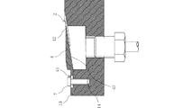
図1(A)及び(B)に示すように、この発明の実施形態に係る気体吐出用ノズル10は、一例として、矩形断面の中実長尺体である金属製又は樹脂製の本体1に、スリット2及び層流通過面3を形成している。本体1の上面は、一端側の所定範囲を除いて、平面状を呈する層流通過面3にされている。本体1の上面における一端側の所定範囲は、層流通過面3に対して所定の層流形成角度で本体1の下面側に向かって傾斜した傾斜面11にされている。傾斜面11における層流通過面3側の一部には、傾斜面11よりも本体1の下面側に位置する傾斜面12が形成されている。傾斜面12は、この発明の第1面に相当する。層流通過面3は、傾斜面11及び12に円弧を介して所定の層流形成角度で連続している。層流形成角度は、5°〜35°の範囲で適宜選択することができる。
As shown in FIGS. 1(A) and 1(B), a
なお、層流通過面3に層流を形成することができることを条件に、層流通過面3と傾斜面11及び12との間の円弧部分を省略することもできる。
Note that the arc portion between the laminar
傾斜面11には、薄板状の金属製又は樹脂製のカバー4が本体1の上面側から固定されている。カバー4は、図示しないネジ又は接着剤によって本体1に固定することができるが、これらに限らず、本体1及びカバー4が金属を素材とする場合には溶接によって本体1に固定することができる。カバー4の上面41における層流通過面3側の所定範囲は、カバー4の下面42との間に楔状を呈するように傾斜している。カバー4の下面42は、この発明の第2面に相当する。
A thin plate-shaped metal or
本体1には、傾斜面11の形範囲内に上面に開放した空間部5が形成されている。下面42を傾斜面11に密着させて固定すると、空間部5の上面側がカバー4によって被覆される。このとき、カバー4の下面42と傾斜面12との間には層流通過面3側に開口を有する間隙が形成され、この間隙がスリット2にされる。したがって、スリット2は、空間部5の層流通過面3側の側面51の上部において、下面42と傾斜面12との間に形成されている。下面42の開口側の端部は、層流通過面3よりも傾斜面12側に位置している。このため、カバー4の全体は層流通過面3よりも下方に位置し、層流通過面3の上方に突出しない。
The
空間部5の底面52には、本体1の下面に貫通したネジ孔53が形成されている。スリット2とネジ孔53とは、空間部5における互いに異なる面に形成されている。ネジ孔53は、この発明の流入口に相当する。ネジ孔53には、下方から接続器具6のネジ部が螺合している。接続器具6は、軸方向の貫通孔61を備えている。貫通孔61及びネジ孔53を経由して、空間部5内に図示しない供給装置から圧縮気体を含む高圧気体が供給される。
The
貫通孔61及びネジ孔53を経由して空間部5内に供給された高圧気体は、下面42と傾斜面12との間のスリット2から吐出され、図1(A)中に二点鎖線矢印で示すように、外気を取り込みながら、層流通過面3に沿う層流を形成してスリット2から離間していく。
The high-pressure gas supplied into the space 5 through the through
図2(A)及び(B)に示すように、一例として、層流形成角度を16°、本体1の幅を30mm、スリット2の高さ(傾斜面12と下面42との間隔。図1参照。)を0.5mm、スリット2の幅をmmとした気体吐出用ノズル10において、空間部5に0.8MPaの高圧気体を供給した場合、スリット2から略175mmまでは本体1の幅で高さ5mmの層流通過面3に沿う気流が維持される。スリット2から475mm離間下位置では、気流の幅は約150mm、気流の高さは約50mmに拡がる。
As shown in FIGS. 2A and 2B, as an example, the laminar flow forming angle is 16°, the width of the
なお、各部の寸法はこれに限るものではなく、例えば、層流形成角度は5°〜35°の範囲で選択することができ、本体1の幅は10〜100mmの範囲で選択することができる。
The size of each part is not limited to this. For example, the laminar flow forming angle can be selected in the range of 5° to 35°, and the width of the
スリット2から吐出された高圧気体は、外気を二次気体として誘引することで増量されて吐出量よりも多量の気流を形成する。この気流により、例えばシート体等の軽量の被搬送物を矢印C方向に沿って層流通過面3の表面から浮遊させて搬送することができる。層流通過面3の長さが150mm程度の気体吐出用ノズル10を矢印C方向に沿って複数連続させて配置することにより、上記の寸法及び圧力で被搬送物を所望の搬送距離にわたって安定して搬送することができる。
The high-pressure gas discharged from the
気体吐出用ノズル10が形成する層流気体を被搬送物の搬送に補助的に使用する場合には、層流通過面3の長さを450mm程度とすることもできる。層流通過面3は、搬送ガイドとして利用できる。スリット2は層流通過面3よりも外側に突出しないため、複数の気体吐出用ノズル10を搬送方向に沿って連続させて配置した場合にも、スリット2が搬送の障害となることがない。
When the laminar flow gas formed by the
また、搬送中の被搬送物の表面に付着した液滴を除去する目的で気体吐出用ノズル10を使用する場合、スリット2から吐出した高圧気体によって液滴の除去と同時に搬送を補助することができ、搬送効率を向上させることができる。
Further, when the
さらに、スリット2から吐出された高圧気体は、外気を二次気体として誘引するため、排気装置等の気体搬送装置として使用することができる。
Furthermore, since the high-pressure gas discharged from the
なお、層流通過面3は、本体1に一体的に形成する必要はなく、スリット2を構成する第1面に層流形成角度で連続することを条件に、別部品で構成することもできる。
The laminar
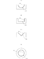
図3に示すように、カバー4を本体1の上面に沿ってスライド自在にすることにより、スリット2の高さを調整できるようにしてもよい。固定ネジ7のネジ部をカバー4に形成した長孔43に貫通させた後に取付面13のネジ穴14に螺合させ、固定ネジ7の頭部でカバー4を取付面13に圧着させて固定する。
As shown in FIG. 3, the height of the
図4(A)〜(D)に示すように、層流通過面3は平面に限るものではなく、被搬送物の形状に応じて、層流通過面103〜403のように、高圧気体の吐出方向(被搬送物の搬送方向)に直交する断面形状を円弧状、矩形状若しくは角状の凹断面、又は筒状とし、スリット102〜402をこれに応じた形状とすることができる。
As shown in FIGS. 4(A) to 4(D), the laminar
また、層流通過面3は、高圧気体の吐出方向に平行な断面において必ずしも直線である必要はなく、高圧気体の層流が剥離しない範囲で湾曲させることもできる。
Further, the laminar
図5に示す気体吐出用ノズル410は、円筒状の本体401を備えている。本体401の外周面には軸方向における中間部の傾斜面412を挟んで大径部と小径部とが形成されており、大径部が円筒状の層流通過面403にされている。層流通過面403は、この発明の第1面に相当する傾斜面412に所定の層流形成角度で連続している。本体401の内周面は、小径部側から中間部に向かって縮径された後、大径部側の端部に向かって拡径され、軸を含む断面は層流通過面403との間に楔状を呈している。
The
本体401の外周面の小径部には、軸方向の一部に全周にわたる凹状の空間部405が形成されており、空間部405を覆う円筒状のカバー404が外嵌している。カバー404の内周面の一端部には、この発明の第2面に相当する傾斜面442が、傾斜面412と同一の角度で形成されている。傾斜面412と傾斜面442との間にスリット402がカバー401の全周にわたって形成される。カバー404には、周面の少なくとも1カ所に空間部405を外部に連通する貫通孔53が形成されている。
In the small diameter portion of the outer peripheral surface of the
本体401の外周面の小径部の端部には、調整ナット412が螺合するネジ部411が形成されている。調整ナット412は、カバー404における傾斜面412とは反対側の端部に回転自在に固定されている。ネジ部411に螺合した調整ナット412を正逆回転させることで、カバー404が軸方向に進退し、傾斜面412と傾斜面442との間隔が調整される。
A threaded
層流通過面403の一部を円筒状の被処理物400の内部に挿入した状態で、貫通孔453を経由して空間部405に高圧気体を供給すると、高圧気体は傾斜面412と傾斜面442との間のスリット402から吐出され、カバー404の外側に位置する外気を誘引しつつ層流通過面403の表面に沿って層流を形成する。この層流が本体1の大径部側の端部に達すると、さらに本体1の内部を経由して本体1の小径部側の端部の外側に位置する外気を誘引しつつ、被処理物400の内周面に沿って層流を形成する。大量の気体が被処理物400の内周面に沿って流れるこたにより、被処理物400の内周面に付着した液滴を確実に除去できる。
When a high-pressure gas is supplied to the
図6に示すように、この発明の第1の実施形態に係る搬送装置100は、気体吐出用ノズル10、コンベア101、圧縮エアポンプ102、調整バルブ103を備えている。コンベア101は、上面に搭載された円柱状の被搬送物Cを搬送方向Xに沿って連続して搬送する。
As shown in FIG. 6, the
気体吐出用ノズル10は、図1及び図2に示した構成を有する。一対の気体吐出用ノズル10は、各層流通過面3が対向する状態でコンベア101を挟んで互いに平行に配置されている。また、各気体吐出用ノズル10は、それぞれの層流通過面3を搬送方向Xに沿って配置されている。一対の気体吐出用ノズル10の各層流通過面3の間隔は、被搬送物Cの直径に略等しくされている。気体吐出用ノズル10は、スリット2側の端部を搬送方向Xの上流側に位置させて配置される。
The
圧縮エアポンプ102は、所謂コンプレッサを含み、外気を圧縮した高圧空気を調整バルブ103を介して気体吐出用ノズル10に供給する。圧縮エアポンプ102がこの発明の気体供給装置に相当し、調整バルブ103が同じく圧力調整機構に相当する。圧縮エアポンプ102は、高圧空気を供給するものに限るものではなく、搬送装置100の設置場所における環境性及び安全性が確保されることを条件に空気以外の高圧気体を供給するものを用いることができる。
The
図6に示す例では、一対の気体吐出用ノズル10のそれぞれに個別に圧縮エアポンプ102及び調整バルブ103を備えているが、単一の圧縮エアポンプ102から単一又は個別の調整バルブ103を介して一対の気体吐出用ノズル10のそれぞれに高圧空気を供給することもできる。
In the example shown in FIG. 6, each of the pair of
圧縮エアポンプ102から調整バルブ103を介して気体吐出用ノズル10に供給された高圧空気は、スリット2から吐出されてスリット2の周囲の外気を誘引しつつ層流通過面3に沿う多量の空気の層流となって搬送方向Xの上流側から下流側に流れる(図中二点鎖線矢印参照。)。
The high-pressure air supplied from the
気体吐出用ノズル10の層流通過面3に形成される層流の気流方向がコンベア101による被搬送物Cの搬送方向Xに一致するため、被搬送物Cはコンベア101の搬送速度よりも高速で搬送方向Xに沿って移動する。一対の気体吐出用ノズル10の層流通過面3は、コンベア101を挟んで互いに平行に配置されているため、搬送ガイドとして被搬送物Cの搬送方向を規定することができ、被搬送物Cがコンベア101から逸脱することがない。被搬送物Cの表面に付着している液滴は、気体吐出用ノズル10の層流通過面3に形成される高圧空気の層流によって除去される。
Since the air flow direction of the laminar flow formed on the laminar
一対の気体吐出用ノズル10の層流通過面3は、コンベア101を挟んで互いに平行に配置されているため、搬送ガイドとして被搬送物Cの搬送方向を規定することができ、被搬送物Cがコンベア101から逸脱することがない。被搬送物Cの表面に付着している液滴は、気体吐出用ノズル10の層流通過面3に形成される高圧気体の層流によって除去される。
Since the laminar flow passage surfaces 3 of the pair of
調整バルブ103による各気体吐出ノズル10に対する高圧空気の供給量を変化させることにより、コンベア101によって搬送中の被搬送物Cを回転させることができる。例えば、図6中上側の気体吐出ノズル10に対する高圧空気の供給量を図6中下側の気体吐出用ノズル10に対する高圧空気の供給量よりも小さくすると、被搬送物Cは矢印R方向に回転する。この回転によって被搬送物Cの全周から液滴を除去することができる。
By changing the supply amount of high-pressure air to each
図7に示すように、一方の気体吐出用ノズル10に代えて搬送ガイド104を備えることでも、被搬送物Cを矢印R方向に回転させることができ、被搬送物Cの表面の全周に高圧空気の層流を接触させることができる。
As shown in FIG. 7, by providing the
また、図8に示すように、被搬送物Cの寸法形状及び周面に対する液滴の付着状態等に応じて、被搬送物Cの搬送方向Xにおける下流側から上流側に向かって気体吐出用ノズル10のスリット2からフ層流通過面3に沿って高圧空気を吐出させることもできる。被搬送物Cの搬送速度は低下するが、被搬送物Cを矢印R′方向に確実に回転させることができ、被搬送物Cの周面の全面から液滴を除去するためにコンベア101に被搬送物Cの回転機構を備える必要がない。
Further, as shown in FIG. 8, for gas ejection from the downstream side to the upstream side in the transport direction X of the transported object C, depending on the size and shape of the transported object C, the attachment state of droplets on the peripheral surface, and the like. High-pressure air can be discharged from the
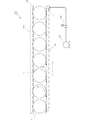
さらに、図9に示すように、複数の気体吐出用ノズル10を被搬送物Cの高さ方向に搬送方向Xに直交する方向に対して傾斜させて並べて配置することもできる。複数の気体吐出用ノズル10の各スリット2から各層流通過面3に沿って吐出される層流の高圧空気により、重量が比較的重い被搬送物Cを確実に回転させることができる。
Further, as shown in FIG. 9, a plurality of
また、図10に示すように、カバー4の上面に副カバー501によってタンク502を形成し、タンク502にソケット503及び液体用ノズル505を備えることもできる。タンク502内には、ソケット503を介して外部から水等の洗浄用液体を導入する。液体用ノズル505は、先端部をスリット2に近接させて配置する。接続器具6を介して空間部5に供給された高圧気体がスリット2から吐出される際に、液体用ノズル505の先端部の周囲が負圧にされ、タンク502内の洗浄用液体が液体用ノズル505を経由して吸い出される。液体用ノズル505から吸い出された洗浄用液体は、層流の高圧気体とともに層流通過面3に沿って噴出され、被搬送物を洗浄する。
Further, as shown in FIG. 10, the
副カバー501は、カバー4の上面に接着、ネジ止め又は溶接等、素材に応じた方法で固定することができる。副カバー501は、被搬送物の搬送性を考慮して、カバー4の上面側への突出量をできるだけ小さくすべきである。
The sub-cover 501 can be fixed to the upper surface of the
なお、上記の実施形態はいずれも一例であり、この発明はこれらに限定されるものではなく、この発明の範囲内で種々の変更を加えることが可能である。例えば、層流通過面3は、高圧気体の吐出方向について層流が剥離しない範囲で湾曲させることもできる。
It should be noted that the above embodiments are all examples, and the present invention is not limited to these, and various modifications can be made within the scope of the present invention. For example, the laminar
1−本体
2−スリット
3−層流通過面
4−カバー
5−空間部
10−気体吐出用ノズル
12−傾斜面(第1面)
42−下面(第2面)
53−ネジ孔(流入口)
100,200,300−搬送装置
102−圧縮エアポンプ(気体供給装置)
103−調整バルブ(圧力調整機構)
C−被搬送物
1-Main Body 2-Slit 3-Laminar Flow Passing Surface 4-Cover 5-Space 10-Gas Discharge Nozzle 12-Inclined Surface (First Surface)
42-bottom surface (second surface)
53-Screw Hole (Inlet)
100, 200, 300-Transfer device 102-Compressed air pump (gas supply device)
103-Adjusting valve (pressure adjusting mechanism)
C-object to be transported
Claims (4)
前記空間部の前記上面側を被覆するカバーと、を備え、
前記スリットは、前記本体内における前記空間部から前記層流通過面に至る間に形成された第1面であって前記層流通過面に向けて吐出した高圧気体が前記層流通過面に沿う前記長手方向の層流となる所定の層流形成角度で前記層流通過面に連続する第1面と、前記カバーの下面であって前記第1面に平行で前記第1面よりも前記本体の外側に位置する第2面と、の間隙に前記長手方向に傾斜して交差するように形成されるとともに、前記層流通過面側で前記長手方向に直交する方向に沿って開口し、
前記カバーにおける前記第2面より外側の部分は、前記層流通過面の延長線より前記第1面側に位置し、
前記流入口は、前記本体の前記下面から前記空間部に連通する気体吐出用ノズル。 A laminar flow passage surface formed along the longitudinal direction excluding a predetermined range on the one end side of the upper surface, an inclined surface inclined toward the lower surface side in the predetermined range on the one end side, and a flow into which high-pressure air flows from the outside. A space part having an inlet and a space part open to the upper surface within the shape range of the inclined surface, and a slit for discharging high-pressure gas in the space part toward the laminar flow passage surface is formed. Body,
A cover that covers the upper surface side of the space portion,
The slit is a first surface formed between the space in the main body and the laminar flow passage surface, and the high-pressure gas discharged toward the laminar flow passage surface is along the laminar flow passage surface. A first surface that is continuous with the laminar flow passage surface at a predetermined laminar flow forming angle that is a laminar flow in the longitudinal direction, and a lower surface of the cover that is parallel to the first surface and that is more than the first surface than the main body. A second surface located on the outer side of the second surface is formed so as to intersect with the second surface while being inclined in the longitudinal direction, and is opened along the direction orthogonal to the longitudinal direction on the laminar flow passage surface side,
A portion of the cover outside the second surface is located on the first surface side with respect to an extension of the laminar flow passage surface,
The inflow port is a gas ejection nozzle that communicates with the space from the lower surface of the main body.
請求項1に記載の気体吐出用ノズルと、
前記気体吐出用ノズルに前記高圧気体を供給する気体供給装置と、
を備え、
前記気体吐出用ノズルにおける前記層流通過面を前記被搬送物の搬送方向に沿って配置した搬送装置。 A transport device for transporting an object to be transported,
A gas discharge nozzle according to claim 1;
A gas supply device for supplying the high-pressure gas to the gas discharge nozzle,
Equipped with
A transport device in which the laminar flow passage surface of the gas discharge nozzle is arranged along the transport direction of the transported object.
少なくとも1対の請求項1に記載の気体吐出用ノズルと、
前記気体吐出用ノズルに前記高圧気体を供給する気体供給装置と、
を備え、
前記1対の気体吐出用ノズルを、それぞれの前記層流通過面が前記被搬送物の直径に略等しい間隔で互いに平行に対向するように配置した搬送装置。 A transport device for transporting a columnar object to be transported,
At least one pair of nozzles for discharging gas according to claim 1;
A gas supply device for supplying the high-pressure gas to the gas discharge nozzle,
Equipped with
A conveying device in which the pair of gas discharging nozzles are arranged so that the laminar flow passage surfaces face each other in parallel with each other at intervals substantially equal to the diameter of the conveyed object.
Priority Applications (1)
| Application Number | Priority Date | Filing Date | Title |
|---|---|---|---|
| JP2020038518A JP6745557B2 (en) | 2020-03-06 | 2020-03-06 | Gas discharge nozzle and carrier |
Applications Claiming Priority (1)
| Application Number | Priority Date | Filing Date | Title |
|---|---|---|---|
| JP2020038518A JP6745557B2 (en) | 2020-03-06 | 2020-03-06 | Gas discharge nozzle and carrier |
Related Parent Applications (1)
| Application Number | Title | Priority Date | Filing Date |
|---|---|---|---|
| JP2017121328A Division JP6750779B2 (en) | 2017-06-21 | 2017-06-21 | Gas discharge nozzle and carrier |
Publications (2)
| Publication Number | Publication Date |
|---|---|
| JP2020099908A JP2020099908A (en) | 2020-07-02 |
| JP6745557B2 true JP6745557B2 (en) | 2020-08-26 |
Family
ID=71140609
Family Applications (1)
| Application Number | Title | Priority Date | Filing Date |
|---|---|---|---|
| JP2020038518A Active JP6745557B2 (en) | 2020-03-06 | 2020-03-06 | Gas discharge nozzle and carrier |
Country Status (1)
| Country | Link |
|---|---|
| JP (1) | JP6745557B2 (en) |
-
2020
- 2020-03-06 JP JP2020038518A patent/JP6745557B2/en active Active
Also Published As
| Publication number | Publication date |
|---|---|
| JP2020099908A (en) | 2020-07-02 |
Similar Documents
| Publication | Publication Date | Title |
|---|---|---|
| US8382013B2 (en) | Air knife | |
| US9150022B2 (en) | Printing apparatus | |
| US8960572B2 (en) | Air manifold having nozzles | |
| US9080728B2 (en) | Wiping device, ink-jet device, and wiping method | |
| JP6253249B2 (en) | Pneumatic solid material transfer pump | |
| US20110048557A1 (en) | Mounting system for fluid discharge devices | |
| JP4868987B2 (en) | Container lid foreign substance removal device | |
| JP6745557B2 (en) | Gas discharge nozzle and carrier | |
| JP6396123B2 (en) | Powder coating equipment | |
| JP5453829B2 (en) | Droplet discharge device | |
| JP6791998B2 (en) | Conveyor device and image forming device | |
| US6899327B2 (en) | Sheet guide apparatus | |
| JP6750779B2 (en) | Gas discharge nozzle and carrier | |
| US4274812A (en) | Jet pump | |
| JP2004174845A (en) | Cleaning device for inkjet head | |
| FR3031059A1 (en) | ||
| JP5794516B2 (en) | Powder conveying device | |
| TW201900505A (en) | Funnel device | |
| JP2003251289A (en) | Dust collector for chute conveying article | |
| JP2001314806A (en) | Powder coating feeder | |
| JP2018083196A (en) | Dust collection device | |
| JP3929284B2 (en) | Parts alignment supply device | |
| TWI510379B (en) | An ink tank, and an ink stirring method using the ink tank | |
| JP3230634U (en) | Gas discharge nozzle | |
| JP7044618B2 (en) | Etching device |
Legal Events
| Date | Code | Title | Description |
|---|---|---|---|
| A621 | Written request for application examination |
Free format text: JAPANESE INTERMEDIATE CODE: A621 Effective date: 20200306 |
|
| A871 | Explanation of circumstances concerning accelerated examination |
Free format text: JAPANESE INTERMEDIATE CODE: A871 Effective date: 20200306 |
|
| A975 | Report on accelerated examination |
Free format text: JAPANESE INTERMEDIATE CODE: A971005 Effective date: 20200616 |
|
| TRDD | Decision of grant or rejection written | ||
| A01 | Written decision to grant a patent or to grant a registration (utility model) |
Free format text: JAPANESE INTERMEDIATE CODE: A01 Effective date: 20200707 |
|
| A61 | First payment of annual fees (during grant procedure) |
Free format text: JAPANESE INTERMEDIATE CODE: A61 Effective date: 20200729 |
|
| R150 | Certificate of patent or registration of utility model |
Ref document number: 6745557 Country of ref document: JP Free format text: JAPANESE INTERMEDIATE CODE: R150 |
|
| S531 | Written request for registration of change of domicile |
Free format text: JAPANESE INTERMEDIATE CODE: R313531 |
|
| R350 | Written notification of registration of transfer |
Free format text: JAPANESE INTERMEDIATE CODE: R350 |
|
| R250 | Receipt of annual fees |
Free format text: JAPANESE INTERMEDIATE CODE: R250 |