JP6744758B2 - Image forming device - Google Patents
Image forming device Download PDFInfo
- Publication number
- JP6744758B2 JP6744758B2 JP2016097388A JP2016097388A JP6744758B2 JP 6744758 B2 JP6744758 B2 JP 6744758B2 JP 2016097388 A JP2016097388 A JP 2016097388A JP 2016097388 A JP2016097388 A JP 2016097388A JP 6744758 B2 JP6744758 B2 JP 6744758B2
- Authority
- JP
- Japan
- Prior art keywords
- image
- scanning direction
- sub
- detection
- pattern
- Prior art date
- Legal status (The legal status is an assumption and is not a legal conclusion. Google has not performed a legal analysis and makes no representation as to the accuracy of the status listed.)
- Active
Links
Images


Classifications
-
- G—PHYSICS
- G03—PHOTOGRAPHY; CINEMATOGRAPHY; ANALOGOUS TECHNIQUES USING WAVES OTHER THAN OPTICAL WAVES; ELECTROGRAPHY; HOLOGRAPHY
- G03G—ELECTROGRAPHY; ELECTROPHOTOGRAPHY; MAGNETOGRAPHY
- G03G15/00—Apparatus for electrographic processes using a charge pattern
- G03G15/50—Machine control of apparatus for electrographic processes using a charge pattern, e.g. regulating differents parts of the machine, multimode copiers, microprocessor control
- G03G15/5054—Machine control of apparatus for electrographic processes using a charge pattern, e.g. regulating differents parts of the machine, multimode copiers, microprocessor control by measuring the characteristics of an intermediate image carrying member or the characteristics of an image on an intermediate image carrying member, e.g. intermediate transfer belt or drum, conveyor belt
-
- G—PHYSICS
- G03—PHOTOGRAPHY; CINEMATOGRAPHY; ANALOGOUS TECHNIQUES USING WAVES OTHER THAN OPTICAL WAVES; ELECTROGRAPHY; HOLOGRAPHY
- G03G—ELECTROGRAPHY; ELECTROPHOTOGRAPHY; MAGNETOGRAPHY
- G03G15/00—Apparatus for electrographic processes using a charge pattern
- G03G15/01—Apparatus for electrographic processes using a charge pattern for producing multicoloured copies
- G03G15/0142—Structure of complete machines
- G03G15/0178—Structure of complete machines using more than one reusable electrographic recording member, e.g. one for every monocolour image
- G03G15/0189—Structure of complete machines using more than one reusable electrographic recording member, e.g. one for every monocolour image primary transfer to an intermediate transfer belt
-
- G—PHYSICS
- G03—PHOTOGRAPHY; CINEMATOGRAPHY; ANALOGOUS TECHNIQUES USING WAVES OTHER THAN OPTICAL WAVES; ELECTROGRAPHY; HOLOGRAPHY
- G03G—ELECTROGRAPHY; ELECTROPHOTOGRAPHY; MAGNETOGRAPHY
- G03G15/00—Apparatus for electrographic processes using a charge pattern
- G03G15/50—Machine control of apparatus for electrographic processes using a charge pattern, e.g. regulating differents parts of the machine, multimode copiers, microprocessor control
- G03G15/5054—Machine control of apparatus for electrographic processes using a charge pattern, e.g. regulating differents parts of the machine, multimode copiers, microprocessor control by measuring the characteristics of an intermediate image carrying member or the characteristics of an image on an intermediate image carrying member, e.g. intermediate transfer belt or drum, conveyor belt
- G03G15/5058—Machine control of apparatus for electrographic processes using a charge pattern, e.g. regulating differents parts of the machine, multimode copiers, microprocessor control by measuring the characteristics of an intermediate image carrying member or the characteristics of an image on an intermediate image carrying member, e.g. intermediate transfer belt or drum, conveyor belt using a test patch
-
- G—PHYSICS
- G03—PHOTOGRAPHY; CINEMATOGRAPHY; ANALOGOUS TECHNIQUES USING WAVES OTHER THAN OPTICAL WAVES; ELECTROGRAPHY; HOLOGRAPHY
- G03G—ELECTROGRAPHY; ELECTROPHOTOGRAPHY; MAGNETOGRAPHY
- G03G2215/00—Apparatus for electrophotographic processes
- G03G2215/01—Apparatus for electrophotographic processes for producing multicoloured copies
- G03G2215/0151—Apparatus for electrophotographic processes for producing multicoloured copies characterised by the technical problem
- G03G2215/0158—Colour registration
- G03G2215/0161—Generation of registration marks
Description
本発明は、画像信号に基づいて画像を形成するプリンタ・複写機・記録機・ファクシミリなどの画像形成装置に関する。 The present invention relates to an image forming apparatus such as a printer, a copying machine, a recording machine, and a facsimile that forms an image based on an image signal.
近年、電子写真方式を採用した画像形成装置による印刷が広く行われている。各色の画像形成部を独立して設けた、所謂、タンデム方式のカラー画像形成装置では、各色の画像形成部における機械的要因や環境的要因により、画像を重ね合わせたときに色ずれが生じ得る。色ずれが発生すると、エッジのにじみや色むらが生じ画質が劣化する。特に、光走査部と感光体を各色のトナー像を形成する画像形成部にそれぞれ設ける構成では、定常的な色ずれ(以下、DC色ずれと呼ぶ)が生じ得る。 In recent years, printing by an image forming apparatus adopting an electrophotographic method has been widely performed. In the so-called tandem type color image forming apparatus in which the image forming units for the respective colors are independently provided, a color shift may occur when the images are superposed due to mechanical factors or environmental factors in the image forming units for the respective colors. .. When the color shift occurs, the blurring of the edge and the color unevenness occur and the image quality deteriorates. In particular, in a configuration in which the optical scanning unit and the photoconductor are provided in the image forming units that form the toner images of the respective colors, steady color misregistration (hereinafter referred to as DC color misregistration) may occur.
DC色ずれを補正するため、画像形成装置は、感光体から転写ベルトに色ずれ量を検出するためのトナー像(以下、検出パターンと呼ぶ)を転写し、各色のトナー像の相対位置をセンサにより検出し、検出結果に基づいて色ずれ補正を行う。しかしながら、感光体や転写ベルトを駆動するローラの偏心、転写ベルトの厚みムラなどの要因により、感光体や転写ベルトに周期的な回転速度の変動が発生する。これら回転速度の変動により、転写ベルト上の検出パターンの形成位置によって色ずれ量が変化する非定常的な色ずれ(以下、AC色ずれと呼ぶ)が発生する。AC色ずれが生じると、検出パターンの検出結果に基づく色ずれ量に検出誤差が生じる。AC色ずれによる検出誤差を抑えるため、AC色ずれの1周期内に複数の検出パターンを形成し、この検出結果を平均化することが考えられる。特許文献1は、ベルト駆動ローラとその駆動源の周期を同時に打ち消すための検出パターンの配置を開示している。 In order to correct the DC color misregistration, the image forming apparatus transfers a toner image (hereinafter, referred to as a detection pattern) for detecting the color misregistration amount from the photoconductor to the transfer belt, and detects the relative position of each color toner image as a sensor. The color misregistration correction is performed based on the detection result. However, due to factors such as the eccentricity of the roller driving the photoconductor or the transfer belt and the unevenness of the thickness of the transfer belt, the rotational speed of the photoconductor or the transfer belt varies periodically. Due to these fluctuations in the rotational speed, unsteady color shift (hereinafter referred to as AC color shift) in which the amount of color shift changes depending on the position where the detection pattern is formed on the transfer belt. When the AC color shift occurs, a detection error occurs in the color shift amount based on the detection result of the detection pattern. In order to suppress the detection error due to the AC color shift, it is possible to form a plurality of detection patterns within one cycle of the AC color shift and average the detection results. Japanese Unexamined Patent Application Publication No. 2004-242242 discloses an arrangement of detection patterns for canceling the cycles of the belt drive roller and its drive source at the same time.
画像形成装置において、AC色ずれを生じさせる回転部材が複数ある場合がある。また、1つの回転部材から、当該回転部材の1回転の周期のAC色ずれのみならず、その1/2、1/3周期成分といった高調波のAC色ずれが生じる場合がある。この様な場合、画像形成装置には、複数周期のAC色ずれが生じる。また、AC色ずれの時間変化が正弦波状にならない場合もある。これらAC周期を抑制するには、多くの検出パターンを形成する必要があるが、消費するトナー量が増大する。また、検出パターンの検出後、転写ベルトの検出パターンを除去する必要があり、クリーニング部の負荷が増加する。さらに、限られた領域内に配置できる検出パターンの数には制限がある。 In the image forming apparatus, there may be a plurality of rotating members that cause AC color shift. In addition, not only the AC color shift of one rotation cycle of the rotary member but also the AC color shift of harmonics such as 1/2 and 1/3 cycle components may occur from one rotating member. In such a case, the AC color shift of a plurality of cycles occurs in the image forming apparatus. In addition, there are cases where the AC color shift does not have a sinusoidal change with time. To suppress these AC cycles, it is necessary to form many detection patterns, but the amount of toner consumed increases. Further, after the detection pattern is detected, it is necessary to remove the detection pattern on the transfer belt, which increases the load on the cleaning unit. Furthermore, there is a limit to the number of detection patterns that can be arranged in a limited area.
本発明は、効果的にAC色ずれを抑制できる画像形成装置を提供するものである。 The present invention provides an image forming apparatus capable of effectively suppressing AC color shift.
本発明の一側面によると、画像形成装置は、感光体にトナー像を形成し、前記感光体のトナー像を、回転駆動される像担持体に転写することで、前記像担持体に検出パターンを形成する形成手段と、前記検出パターンを検出する検出手段と、前記検出手段による前記検出パターンの検出結果に基づき色ずれ補正制御を行う制御手段と、を備えており、前記検出パターンは、前記像担持体の回転方向である副走査方向に沿って第1間隔で配置された複数の基本パターンを含み、前記複数の基本パターンのそれぞれは、前記副走査方向に沿って第2間隔で配置されたN個の画像群(Nは3以上の整数)を含み、前記N個の画像群は、前記副走査方向に対して第1角度の画像を含む第1画像群と、前記副走査方向に対して前記第1角度とは異なる第2角度の画像を含む第2画像群と、を前記副走査方向に沿って交互に配置したものであり、前記第1間隔は、前記感光体又は前記感光体を駆動するモータの回転周期に対応する第1周期のM(Mは2以上の整数)倍の期間に前記像担持体の表面が移動する距離に対応し、前記第2間隔は、前記第1周期の(N−1)分の1の期間に前記像担持体の表面が移動する距離に対応することを特徴とする。 According to one aspect of the present invention, an image forming apparatus forms a toner image on a photoconductor, and transfers the toner image on the photoconductor to an image carrier that is rotationally driven to detect a detection pattern on the image carrier. Forming means for forming, a detection means for detecting the detection pattern, and a control means for performing color misregistration correction control based on the detection result of the detection pattern by the detection means, wherein the detection pattern is A plurality of basic patterns are arranged at a first interval along a sub-scanning direction which is a rotation direction of the image carrier, and each of the plurality of basic patterns is arranged at a second interval along the sub-scanning direction. And N image groups (N is an integer of 3 or more), the N image groups including a first image group including an image at a first angle with respect to the sub-scanning direction and the N image group in the sub-scanning direction. On the other hand, a second image group including an image of a second angle different from the first angle is alternately arranged along the sub-scanning direction, and the first interval is the photoconductor or the photoconductor. The second interval corresponds to the distance that the surface of the image carrier moves in a period of M times (M is an integer of 2 or more) times the first cycle corresponding to the rotation cycle of the motor that drives the body . It corresponds to the distance traveled by the surface of the image carrier in a period of (N-1)th of one cycle.
本発明によると、効果的にAC色ずれを抑制できる。 According to the present invention, AC color shift can be effectively suppressed.
以下、本発明の例示的な実施形態について図面を参照して説明する。なお、以下の実施形態は例示であり、本発明を実施形態の内容に限定するものではない。また、以下の各図においては、実施形態の説明に必要ではない構成要素については図から省略する。 Hereinafter, exemplary embodiments of the present invention will be described with reference to the drawings. The following embodiments are exemplifications, and the present invention is not limited to the contents of the embodiments. Further, in each of the following drawings, components that are not necessary for explaining the embodiment are omitted from the drawings.
<第一実施形態>
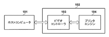
図1は、本実施形態による画像形成装置102を含むシステム構成図である。ホストコンピュータ101が画像形成装置102に画像データを送信して画像形成を指示すると、画像形成装置102は画像形成を行う。ビデオコントローラ103は、ホストコンピュータ101から画像形成が指示されると、色変換やハーフトーン処理などの各種データ処理を行い、プリンタエンジン104に処理後の画像データを送信して画像形成を指示する。プリンタエンジン104は、ビデオコントローラ103から画像形成が指示されると、受信する画像データに従い図2に示す画像形成装置の機構部を制御して記録媒体に画像形成を行う。
<First embodiment>
FIG. 1 is a system configuration diagram including an
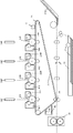
図2は、プリンタエンジン104が制御する画像形成装置の機構部を示す断面図である。図2において、参照符号の末尾のアルファベットY、M、C、Kは、それぞれ、対応する部材が形成に関わるトナー像の色が、イエロー、マゼンタ、シアン、ブラックであることを示している。なお、以下の説明において、色を区別する必要が無い場合には、末尾のアルファベットを除いた参照符号を使用する。感光体22は、画像形成時、図の反時計周り方向に回転駆動される。露光部23は、感光体22の表面を一様な電位に帯電させる。光走査部24は、一様な電位に帯電された感光体22を、画像データに基づき露光して静電潜像を形成する。現像部26は、感光体22に形成された静電潜像をトナーで現像しトナー像として可視化する。感光体22のトナー像は、像担持体である転写ベルト27に転写される。なお、各感光体22のトナー像を重ねて転写ベルト27に転写することで、転写ベルト27には、フルカラーのトナー像が形成される。
FIG. 2 is a sectional view showing a mechanical portion of the image forming apparatus controlled by the
転写ベルト27は、画像形成時、駆動ローラ25により図の時計周り方向に回転駆動される。これにより、転写ベルト27のトナー像は、転写ローラ28の対向位置へと搬送される。一方、カセット21a又はトレイ21bの記録媒体11は、転写ベルト27のトナー像が転写ローラ28の対向位置へと搬送されるタイミングに合わせて、転写ローラ28の対向位置へと搬送される。そして、転写ローラ28は、転写ベルト27のトナー像を、搬送路を搬送される記録媒体11に転写する。クリーニング部29は、記録媒体11に転写されず、転写ベルト27に残留したトナーを除去する。トナー像の転写後、記録媒体11は、定着部30に搬送される。定着部30は、記録媒体11を加熱・加圧してトナー像を記録媒体11に定着させる。トナー像の定着後、記録媒体11は、画像形成装置外へと排出される。センサ6は、転写ベルト27の対向位置に設けられており検出パターンを検出する。
The
図3は、プリンタエンジン104の概略的な構成図である。プリンタエンジン104のエンジン制御部301は、図2に示す機構部302を制御して画像形成を行う。CPU303は、RAM305を主メモリ、ワークエリアとして利用し、不揮発性記憶部306に格納される各種制御プログラムに従い機構部の制御を行う。また、ASIC304も、CPU303の指示のもと、CPU303と協働して機構部を制御する。エンジンインタフェース部(I/F)307は、ビデオコントローラ103との通信部である。エンジン制御部301の各機能ブロックは、システムバス312により相互に通信可能な様に構成されている。なお、CPU303の機能の一部或いは全てをASIC304に行わせても良く、また、逆にASIC304の機能の一部或いは全てをCPU303に行なわせても良い。また、別途の専用ハードウェアを設け、CPU303やASIC304の機能の一部をその専用ハードウェアに行なわせるようにしても良い。
FIG. 3 is a schematic configuration diagram of the
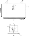
図4は、本実施形態によるセンサ6の説明図である。図4(A)に示す様に、センサ6は、転写ベルト27の搬送方向と直交する方向の端部、それぞれに、設けられる。なお、その一方をセンサ6Lと呼び、他方をセンサ6Rと呼ぶ。しかしながら、2つのセンサを区別する必要が無い場合にはセンサ6と表記する。図4(B)は、センサ6の構成図である。発光部61は、例えば、LEDであり、転写ベルト27に向けて光を照射する。受光部62は、例えば、フォトトランジスタであり、発光部61が照射し、転写ベルト27の表面や、その上に形成された検出パターンでの反射光を受光する。なお、発光部61と受光部62は、光学的に対称となるように、それぞれ、転写ベルト27の法線方向に対して角度Aだけ傾けて配置する。これにより、受光部62は、主に、転写ベルト27での正反射光を受光する。なお、乱反射光を検出する別の受光部をさらに設ける構成であっても良い。
FIG. 4 is an explanatory diagram of the
図5は、本実施形態によるセンサ6の制御構成である。なお、センサ制御部51は、例えば、ASIC304により実現される。しかしながら、CPU303により実現しても良い。駆動部52は、センサ6R及び6Lをオン/オフするための駆動信号を出力する。センサ6R及び6Lは、オン状態になると、発光部61が光を照射し、受光部62は、受光強度又は受光量を示す検出信号を出力する。計測部53は、センサ6R及び6Lが出力する検出信号を受信し、閾値と比較することで検出パターンの各色のトナー像の検出タイミングを計測する。演算部55は、検出パターンの各色のトナー像の検出タイミングに基づき色ずれ量を演算し、色ずれを補正するための補正パラメータを求める。なお、本実施形態において、センサ6が出力する検出信号は、受光部62の受光強度に応じた信号であり、計測部53は、検出信号と閾値を比較することで検出パターンの各色のトナー像の検出タイミングを求める。しかしながら、センサ6内で閾値と比較し、センサ6が2値化信号を検出信号として計測部53に出力する構成であっても良い。この場合、計測部53は、2値化信号のエッジに基づき検出パターンの各色のトナー像の検出タイミングを検出する。
FIG. 5 is a control configuration of the
続いて、本実施形態において使用する検出パターンについて説明する。なお、図7において、白抜きの矢印は転写ベルト27の回転方向、つまり、副走査方向を示している。また、副走査方向に直交する方向が主走査方向、つまり、光走査部24による感光体22の走査方向である。また、図7において参照符号701は、センサ6の検出位置を示している。
Next, the detection pattern used in this embodiment will be described. Note that, in FIG. 7, white arrows indicate the rotation direction of the
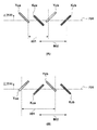
図7(A)は、副走査方向に対して45度の各色の斜線Yza、Mza、Cza、Kzaと、副走査方向に対して−45度の各色の斜線Yzb、Mzb、Czb、Kzbと、を有する。なお、各斜線を示す文字列の最初の文字Y、M、C、Kは、それぞれ、トナーの色が、イエロー、マゼンタ、シアン、ブラックであることを示している。また、以下では、斜線Yza、Mza、Cza、Kzaを含む画像群を第1画像群と呼び、斜線Yzb、Mzb、Czb、Kzbを含む画像群を第2画像群と呼ぶものとする。さらに、第1画像群と第2画像群を区別しない場合、これらを纏めて画像群と呼ぶものとする。本実施形態において、第1画像群と第2画像群は、副走査方向に対して線対称である。 FIG. 7A shows diagonal lines Yza, Mza, Cza, Kza of 45 degrees with respect to the sub-scanning direction, and diagonal lines Yzb, Mzb, Czb, Kzb of −45 degrees with respect to the sub-scanning direction. Have. The first letters Y, M, C, and K of the character string indicating the diagonal lines indicate that the toner colors are yellow, magenta, cyan, and black, respectively. Further, hereinafter, an image group including the diagonal lines Yza, Mza, Cza, and Kza is referred to as a first image group, and an image group including the diagonal lines Yzb, Mzb, Czb, and Kzb is referred to as a second image group. Furthermore, when the first image group and the second image group are not distinguished, they are collectively referred to as an image group. In the present embodiment, the first image group and the second image group are line-symmetric with respect to the sub scanning direction.
図7(A)のパターンは、副走査方向に沿って第2画像群を第1画像群の後側に配置したものであり、図7(B)のパターンは、副走査方向に沿って第2画像群を第1画像群の前側に配置したものである。なお、前側とは、センサ6により先に検出される側であり、下流側とも呼ぶ。一方、後側とは、センサ6により後に検出される側であり、上流側とも呼ぶ。本実施形態では、位置ずれのない理想状態において、画像群内の各斜線の副走査方向の幅をwとし、1つの画像群内の隣接する2つの斜線間のトナーが付着しない部分の副走査方向の幅をsとする。また、前側の画像群の最後の斜線と、後側の画像群の最初の斜線との副走査方向の最短距離をgとする。さらに、各斜線の主走査方向の長さをLsとする。この場合、図7(A)又は(B)に示すパターンの副走査方向の長さLbase=w×8+s×6+Ls×2+gとなる。例えば、w=2[mm]、s=4[mm]、g=4[mm]、Ls=12[mm]であると、図7のパターンの副走査方向の長さLbase=68[mm]となる。なお、画像形成装置は、理想的な状態において、センサ6の検出位置に各斜線の主走査方向の中心が来るように検出パターンを形成する。
The pattern of FIG. 7A is obtained by arranging the second image group on the rear side of the first image group in the sub-scanning direction, and the pattern of FIG. 7B is the second image group in the sub-scanning direction. The two image groups are arranged in front of the first image group. The front side is the side detected first by the
続いて、図7(A)のパターンの検出結果に基づく副走査方向及び主走査方向の色ずれ量の求め方について説明する。なお、以下の説明において、パターン内の各斜線の検出位置を、図7(A)の各斜線を示す文字列にdを付して表す。つまり、例えば、斜線Yzaの検出位置をdYzaと表記する。なお、各斜線の検出位置の求め方については後述する。また、以下では基準色をブラックとし、ブラックに対するイエロー、マゼンタ及びシアンそれぞれの色ずれ量を求めるものとする。 Subsequently, a method of obtaining the color misregistration amount in the sub-scanning direction and the main scanning direction based on the detection result of the pattern of FIG. In addition, in the following description, the detection position of each diagonal line in the pattern is represented by adding a d to the character string indicating each diagonal line in FIG. That is, for example, the detection position of the diagonal line Yza is described as dYza. The method of obtaining the detection position of each diagonal line will be described later. Further, in the following description, it is assumed that the reference color is black and the color shift amounts of yellow, magenta, and cyan with respect to black are obtained.
まず、イエローの副走査方向の色ずれ量は、以下の式により求めることができる。
|(dYza+dYzb)/2−(dKza+dKzb)/2|−3×(w+s)
上記式は、第1画像群及び第2画像群のイエローの斜線の平均位置と、第1画像群及び第2画像群のブラックの斜線の平均位置との距離から、イエローとブラックの副走査方向の理想的な距離を減じたものである。なお、上記式において色ずれ量が負であることは、イエローとブラックの副走査方向の距離が理想より狭くなっていること、つまり、イエローが副走査方向の上流側にずれていることを示している。反対に、色ずれ量が正であることは、イエローとブラックとの副走査方向の距離が理想より広くなっていること、つまり、イエローが副走査方向の下流側にずれていることを示している。マゼンタ及びシアンの副走査方向の色ずれ量も同様の考え方により求めることができる。なお、マゼンタとブラックの理想的な距離は、2×(w+s)であり、シアンとブラックの理想的な距離は(w+s)である。
First, the color shift amount of yellow in the sub-scanning direction can be obtained by the following formula.
|(dYza+dYzb)/2-(dKza+dKzb)/2|-3*(w+s)
The above formula is calculated from the distance between the average position of the diagonal lines of yellow in the first image group and the second image group and the average position of the diagonal lines of black in the first image group and the second image group, in the sub-scanning directions of yellow and black. The ideal distance is reduced. It should be noted that a negative color shift amount in the above equation indicates that the distance between yellow and black in the sub-scanning direction is smaller than the ideal, that is, yellow is shifted upstream in the sub-scanning direction. ing. On the other hand, a positive amount of color misregistration indicates that the distance between yellow and black in the sub-scanning direction is wider than the ideal, that is, yellow is displaced downstream in the sub-scanning direction. There is. The amount of color misregistration of magenta and cyan in the sub-scanning direction can be obtained by the same idea. The ideal distance between magenta and black is 2×(w+s), and the ideal distance between cyan and black is (w+s).
また、イエローの主走査方向の色ずれ量は、以下の式により求めることができる。
(|dKzb−dKza|−|dYzb−dYza|)/2
図8(A)に示す様に、上記式の|dKzb−dKza|は、第1画像群と第2画像群のブラックの斜線の副走査方向の距離802を示している。同様に、|dYzb−dYza|は、第1画像群と第2画像群のイエローの斜線の副走査方向の距離801を示している。したがって、上記式の分子は、距離802から距離801を減じた値を示している。本実施形態において斜線の副走査方向に対する角度の絶対値は45度であるため、距離802と距離801の差は主走査方向の色ずれ量の2倍となる。したがって、距離802から距離801を減じた値を2で割ることで主走査方向の色ずれ量が求められる。図8(A)から明らかな様に、イエローがブラックに対して正側にずれると、距離801は、距離802より小さくなる。なお、本実施形態では、図8(A)の矢印方向が正側のずれとしている。したがって、本実施形態では、距離802から距離801を減じることで、その符号がずれの方向を示すことになる。なお、マゼンタ、シアンについても同様である。
Further, the color shift amount of yellow in the main scanning direction can be obtained by the following formula.
(|dKzb-dKza|-|dYzb-dYza|)/2
As shown in FIG. 8A, |dKzb−dKza| in the above equation indicates the
続いて、図7(B)のパターンの検出結果に基づく副走査方向及び主走査方向の色ずれ量の求め方について説明する。副走査方向の色ずれ量の求め方は図7(A)のパターンと同様である。一方、主走査方向についても、色ずれ量の絶対値の求め方は同じであるが、符号とずれの方向との関係が図7(A)のパターンとは異なる。これは、図8(B)に示す様に、イエローがブラックに対して正側にずれると、距離801が距離802より長くなるからである。つまり、図7(B)のパターンにおいては、図7(A)のパターンと同じ計算式で計算したときにその値が負であると、イエローが正側にずれていることになる。
Subsequently, a method of obtaining the color misregistration amount in the sub-scanning direction and the main scanning direction based on the detection result of the pattern of FIG. 7B will be described. The method of obtaining the amount of color misregistration in the sub-scanning direction is the same as in the pattern of FIG. On the other hand, in the main scanning direction as well, the method of obtaining the absolute value of the color misregistration amount is the same, but the relationship between the sign and the misregistration direction is different from the pattern of FIG. This is because the
以上を踏まえて、本実施形態による検出パターンを図9により説明する。なお、本実施形態の画像形成装置では、感光体22が1回転する周期と、その2倍高調波である感光体の半周期と、転写ベルト27が1回転する周期の3つの周期で、回転ムラによるAC色ずれが発生するものとする。なお、周期は時間であるが、以下では説明の簡略化のため、各周期を、当該周期における転写ベルト27の表面の移動量で示すものとする。具体的には、感光体22が1回転する間の転写ベルト27の表面の移動量をドラム周期Ldと呼び、転写ベルト27が1回転する間の転写ベルト27の表面の移動量をベルト周期Lbと呼ぶものとする。そして、ドラム周期Ldの1/2の周期をドラム半周期と呼ぶものとする。そして、具体的な数値例として、以下では、Ld=108[mm]、Lb=900[mm]を使用する。
Based on the above, the detection pattern according to the present embodiment will be described with reference to FIG. In the image forming apparatus according to the present exemplary embodiment, the photoconductor 22 rotates once in three cycles, a half cycle of the photoconductor that is a double harmonic thereof, and the
図9は、本実施形態における検出パターンを示している。図9は、センサ6Rが検出する検出パターンのみを示しているが、実際には、センサ6Lの検出位置にも同様の検出パターンが形成される。なお、図9の白抜きの矢印は、転写ベルト27の搬送方向、つまり、副走査方向を示している。本実施形態において、検出パターンは、基本パターン901Rと、基本パターン902Rとを含んでいる。基本パターン901R及び902Rは、それぞれ、第1画像群と第2画像群を副走査方向に沿って交互に配置したものである。本実施形態において、基本パターン901R及び902Rそれぞれは、4つの画像群を含んでおり、隣接する2つの画像群の副走査方向の間隔を、ドラム周期Ldの1/3としている。なお、隣接する2つの画像群の副走査方向の間隔とは、主走査方向の所定位置における、前側の画像群の斜線と、後側の画像群の同じ色の斜線との距離である。本実施形態において、所定位置は、斜線の主走査方向の中心位置とする。一般的に述べると、1つの基本パターンにN個(Nは3以上の整数)の画像群を形成する場合、画像群間の副走査方向の間隔を、ドラム周期Ldの1/(N−1)とする。また、基本パターン間の副走査方向の間隔Laを、本実施形態では、ドラム周期Ldの4倍としている。なお、基本パターン間の副走査方向の間隔Laとは、主走査方向の中心位置における、前側の基本パターンの先頭の斜線と、後側の基本パターンの先頭の斜線との距離である。
FIG. 9 shows a detection pattern in this embodiment. Although FIG. 9 shows only the detection pattern detected by the
図9から明らかな様に、基本パターン901Rの隣接する2つの画像群の組904R及び906Rは、図7(A)のパターンを構成し、隣接する2つの画像群の組905Rは、図7(B)のパターンを構成している。同様に、基本パターン902Rの隣接する2つの画像群の組907R及び909Rは、図7(B)のパターンを構成し、隣接する2つの画像群の組908Rは、図7(A)のパターンを構成している。なお、以下の説明において画像群のサイズや間隔に関するパラメータは、図7(A)に示す通りであり、以下の説明では、具体的な数値例として、w=2[mm]、s=4[mm]、g=4[mm]、Ls=12[mm]を使用する。また、以下の説明において、各斜線を特定する場合には、図9の各斜線に付した文字列を使用する。
As is apparent from FIG. 9, two adjacent image group sets 904R and 906R of the
上述した様に、センサ6Rの検出位置903R上での斜線RY0aと斜線RY0bとの距離を、図9に示す様に、ドラム周期Ldの3分の1とする。上記具体的な数値例を適用すると、斜線RY0aと斜線RY0bとの距離は、w×4+s×3+Ls+g=36[mm]であり、これは、ドラム周期Ld=108[mm]の3分の1である。また、上述した様に、基本パターン901Rと902Rとの距離をLaは、Ld×4=432[mm]となる。
As described above, the distance between the oblique line RY0a and the oblique line RY0b on the
続いて、図9の検出パターンの検出結果に基づく副走査方向及び主走査方向の色ずれ量の求め方について説明する。なお、以下の説明において、検出パターンの各斜線の検出位置を、図9の各斜線を示す文字列にdを付して表す。つまり、例えば、斜線RY0aの検出位置をdRY0aと表記する。なお、各斜線の検出位置の求め方については後述する。また、以下では基準色をブラックとし、ブラックに対するイエロー、マゼンタ及びシアンそれぞれの色ずれ量を求めるものとする。 Subsequently, a method of obtaining the color misregistration amounts in the sub-scanning direction and the main scanning direction based on the detection result of the detection pattern of FIG. 9 will be described. In addition, in the following description, the detection position of each diagonal line of the detection pattern is represented by adding d to the character string indicating each diagonal line in FIG. 9. That is, for example, the detection position of the diagonal line RY0a is described as dRY0a. The method of obtaining the detection position of each diagonal line will be described later. Further, in the following description, it is assumed that the reference color is black and the color shift amounts of yellow, magenta, and cyan with respect to black are obtained.
まず、副走査方向の色ずれ量の求め方について説明する。基本的な考え方は、図7(A)及び(B)で説明したのと同様である。しかしながら、上述した様に、本実施形態では、図7(A)、図7(B)で説明したパターンが計6組ある。したがって、各組のパターンの検出結果から求められる副走査方向の色ずれ量を平均化する。代表例として、イエローの副走査方向の色ずれ量dRYsの計算方法を以下に示す。
dRYs=|(dRY0a+dRY0b)+(dRY0b+dRY1a)+(dRY1a+dRY1b)+(dRY2a+dRY2b)+(dRY2b+dRY3a)+(dRY3a+dRY3b)−(dRK0a+dRK0b)−(dRK0b+dRK1a)−(dRK1a+dRK1b)−(dRK2a+dRK2b)−(dRK2b+dRK3a)−(dRK3a+dRK3b)|/12−3×(w+s)
マゼンタ及びシアンについても、ブラックとの理想的な距離が異なる以外は同様である。
First, a method of obtaining the color shift amount in the sub-scanning direction will be described. The basic idea is the same as that described in FIGS. 7A and 7B. However, as described above, in this embodiment, there are a total of six patterns described in FIGS. 7A and 7B. Therefore, the amount of color misregistration in the sub-scanning direction obtained from the detection results of the patterns of each set is averaged. As a representative example, a method of calculating the color shift amount dRYs of yellow in the sub-scanning direction will be described below.
dRYs = | (dRY0a + dRY0b) + (dRY0b + dRY1a) + (dRY1a + dRY1b) + (dRY2a + dRY2b) + (dRY2b + dRY3a) + (dRY3a + dRY3b) - (dRK0a + dRK0b) - (dRK0b + dRK1a) - (dRK1a + dRK1b) - (dRK2a + dRK2b) - (dRK2b + dRK3a) - (dRK3a + dRK3b) |/12-3×(w+s)
The same applies to magenta and cyan, except that the ideal distance from black is different.
続いて、主走査方向の色ずれ量の求め方について説明する。副走査方向と同様に、6つの組のパターンの検出結果から求められる主査方向の色ずれ量を平均化する。代表例として、イエローの主走査方向の色ずれ量dRymの計算方法を以下に示す。
dRYm=(|dRK0b−dRK0a|−|dRK1a−dRK0b|+|dRK1b−dRK1a|−|dRK2b−dRK2a|+|dRK3a−dRK2b|−|dRK3b−dRK3a|)/12−(|dRY0b−dRY0a|−|dRY1a−dRY0b|+|dRY1b−dRY1a|−|dRY2b−dRY2a|+|dRY3a−dRY2b|−|dRY3b−dRY3a|)/12
なお、ブラックとイエローそれぞれについて、平均値を求める際の符号が異なるのは、図7(A)と図7(B)のパターンでは、符号と色ずれの方向との関係が逆であるからである。
Subsequently, a method of obtaining the color shift amount in the main scanning direction will be described. Similar to the sub-scanning direction, the amount of color misregistration in the main scanning direction obtained from the detection results of the six sets of patterns is averaged. As a representative example, a method of calculating the color deviation amount dRym in the main scanning direction of yellow will be described below.
dRYm = (|dRK0b-dRK0a|-|dRK1a-dRK0b|+|dRK1b-dRK1a|-|dRK2b-dRK2a|+|dRK3a-dRK2b|-|dRK3b-dRK3a| dRY1a-dRY0b|+|dRY1b-dRY1a|-|dRY2b-dRY2a|+|dRY3a-dRY2b|-|dRY3b-dRY3a|)/12
It should be noted that the signs when calculating the average value are different for black and yellow, respectively, because the relationship between the signs and the direction of color misregistration is opposite in the patterns of FIGS. 7A and 7B. is there.
図6は、本実施形態による色ずれ補正処理のフローチャートである。なお、画像形成装置は、所定条件が満たされると色ずれ補正処理を開始する。所定条件は、例えば、電源が投入されたとき、前回の色ずれ補正処理から所定枚数の印刷を行ったとき、前回の色ずれ補正処理から所定時間経過したとき、装置内部の温度が所定値以上変動したときに満たされる。しかしながら、その他の条件を使用することもできる。色ずれ補正の開始によりCPU303は、S10で、機構部302を制御して図9の検出パターンを転写ベルト27に形成する。S11で、計測部53は、検出信号に基づき検出パターンを検出する。図10は、1つの斜線に対応するトナー像がセンサ6の検出領域を通過した際の検出信号を示している。図10に示す様に、トナー像での正反射光は、転写ベルト27の表面での正反射光より弱いため、トナー像がセンサ6の検出領域を通過すると検出信号は一旦減少する。計測部53は、検出信号と閾値と比較し、検出信号が閾値を下回ったタイミングte0をトナー像の前側のエッジの検出タイミングとする。そして、計測部53は、検出信号が閾値を上回ったタイミングte1を、トナー像の後側のエッジの検出タイミングとする。計測部53は、この2つの検出タイミングte0及びte1から、検出した斜線の位置を、(te0+te1)/2×Vpとして求める。ここで、Vpは、転写ベルト27の表面の移動速度[mm/sec]である。
FIG. 6 is a flowchart of color misregistration correction processing according to this embodiment. The image forming apparatus starts the color misregistration correction process when a predetermined condition is satisfied. The predetermined condition is, for example, that when the power is turned on, when a predetermined number of sheets are printed from the previous color misregistration correction process, when a predetermined time has elapsed from the previous color misregistration correction process, the temperature inside the apparatus is a predetermined value or more. It is satisfied when it fluctuates. However, other conditions can be used. Upon starting the color misregistration correction, the
演算部55は、S12で、センサ6R及び6Lが検出した検出パターンの各斜線の位置に基づき、上述した様に、センサ6R及び6Lについて副走査方向と主走査方向の色ずれ量を求める。そして、センサ6Rの検出結果に基づき求めた副走査方向と主走査方向の色ずれ量と、センサ6Lの検出結果に基づき求めた副走査方向と主走査方向の色ずれ量に基づき、副走査色ずれ量、主走査色ずれ量、主走査幅、傾き量をそれぞれ求める。以下では、代表してイエローの副走査色ずれ量、主走査色ずれ量、主走査幅、傾き量の求め方について説明する。なお、センサ6Rの検出結果から求めたイエローの副走査方向及び主走査方向の色ずれ量をdRYs及びdRYmとし、センサ6Lの検出結果から求めたイエローの副走査方向及び主走査方向の色ずれ量をdLYs及びdLYmとする。
In S12, the
まず、イエローの副走査色ずれ量dYsは、dRYsとdLYsの平均値として求める。つまり、
dYs=(dRYs+dLYs)/2
である。同様に、イエローの主走査色ずれ量dYmは、dRYmとdLYmの平均値として求める。つまり、
dYm=(dRYm+dLYm)/2
である。
First, the yellow sub-scanning color shift amount dYs is obtained as an average value of dRYs and dLYs. That is,
dYs=(dRYs+dLYs)/2
Is. Similarly, the yellow main scanning color shift amount dYm is obtained as an average value of dRYm and dLYm. That is,
dYm=(dRYm+dLYm)/2
Is.
イエローの主走査幅dYwは、基準色であるブラックに対するイエローの主走査幅の伸縮量であり、
dYw=dRYm−dLYm
により求めるまた、イエローの傾き量dYkは基準色であるブラックに対する走査線の傾き量であり、
dYk=dRYs−dLYs
により求める。
The yellow main scanning width dYw is the amount of expansion/contraction of the yellow main scanning width with respect to the reference color black,
dYw=dRYm-dLYm
Further, the tilt amount dYk of yellow is the tilt amount of the scanning line with respect to the reference color black,
dYk=dRYs-dLYs
Ask by.
演算部55は、S13で、各色の副走査色ずれ量、主走査色ずれ量、主走査幅、傾き量に基づき補正パラメータを計算する。具体的には「副走査色ずれ量」より、副走査方向の色ずれをキャンセルするための感光体22の露光タイミングの調整量を計算する。「主走査色ずれ量」より、主走査方向の色ずれ量をキャンセルするための主走査方向の露光開始タイミングの調整量を計算する。「主走査幅」より、主走査幅のずれをキャンセルするための、主走査幅の補正伸縮率を計算する。「傾き量」からは、走査線の傾きをキャンセルするための傾き補正角度を計算する。演算部55は、S14で、補正パラメータをビデオコントローラ103へと送信し、ビデオコントローラ103は、不図示の不揮発性記憶部に補正パラメータを記録する。画像形成時、ビデオコントローラ103は、記憶した補正パラメータに基づいてプリンタエンジン104に画像形成の指示を行う。
In S13, the
続いて、本実施形態の効果について説明する。例えば、図7(A)又は(B)のパターンの副走査方向の長さは68[mm]である。したがって、ドラム周期Ld(108[mm])の1/3の間隔、すなわち36[mm]の間隔で、図7(A)又は(B)のパターンを配置することはできない。このため、図11に示す検出パターンが考えられる。図11に示す検出パターンは、図7(A)のパターンを3つ、副走査方向に沿って配置したものである。なお、パターン1104Rとパターン1105Rの副走査方向の間隔を、ドラム周期Ldの2/3とし、パターン1104Rとパターン1106Rとの間隔Lpを、Lp=Ld×4+Ld/3としている。したがって、3つのパターンは、ドラム周期Ldを3等分した位相に配置されている。したがって、3つのパターンそれぞれの検出結果を平均することでドラム周期及びドラム半周期のAC色ずれが低減される。
Then, the effect of this embodiment is explained. For example, the length in the sub-scanning direction of the pattern of FIG. 7A or 7B is 68 [mm]. Therefore, the pattern of FIG. 7A or 7B cannot be arranged at an interval of 1/3 of the drum cycle Ld (108 [mm]), that is, an interval of 36 [mm]. Therefore, the detection pattern shown in FIG. 11 can be considered. The detection pattern shown in FIG. 11 is obtained by arranging three patterns shown in FIG. 7A along the sub-scanning direction. The interval between the
なお、上記具体的な数値を適用すると、Lpは、468[mm]であり、ベルト周期Lb(900[mm])の半分の450[mm]に近い値である。つまり、パターン1104Rとパターン1106Rは、ベルト周期の逆位相に近い位置である。しかしながら、パターン1105Rの存在により、3つのパターンの検出結果の平均では、ベルト周期のAC色ずれの影響を低減できない。また、AC色ずれも正弦波ではない波形になる場合もあり、この場合にはドラム周期Ldに対して3組だけの平均化ではAC色ずれが十分に抑圧されず、ドラム周期、及びドラム半周期のAC色ずれの影響を十分に低減できない。
Applying the above specific numerical values, Lp is 468 [mm], which is a value close to 450 [mm], which is half the belt period Lb (900 [mm]). That is, the
一方、本実施形態では、図9を用いて説明した様に、基本パターン内の最初と最後の画像群以外の画像群を、その前側の画像群及び後側の画像群それぞれと組合せて色ずれ量を算出する様にしている。つまり、1つの基本パターンの3つの組の間隔はドラム周期の1/3の間隔である。さらに、基本パターン間の間隔Laは、La=Ld×4である。つまり、前側の基本パターンの3つのパターンそれぞれは、後側の基本パターンの3つのパターンそれぞれと同位相である。したがって、6つのパターンの検出結果を平均化することでドラム周期及びドラム半周期のAC色ずれを低減することができる。 On the other hand, in the present embodiment, as described with reference to FIG. 9, image groups other than the first and last image groups in the basic pattern are combined with the image groups on the front side and the image groups on the rear side, respectively, to cause color misregistration. I try to calculate the amount. That is, the interval between the three sets of one basic pattern is 1/3 of the drum cycle. Further, the interval La between the basic patterns is La=Ld×4. That is, each of the three basic patterns on the front side has the same phase as each of the three basic patterns on the rear side. Therefore, by averaging the detection results of the six patterns, it is possible to reduce the AC color shift in the drum cycle and the drum half cycle.
さらに、2つの基本パターンの間隔Laは、La=4×Ld=432[mm]と、ベルト周期の1/2=450[mm]に近い値である。また、上述した様に、2つの基本パターンの3つの組それぞれは同位相である。6つの組の検出結果を平均化することは、基本パターン901Rの3つの組の検出結果の平均と、基本パターン902Rの3つの組の検出結果の平均との平均を求めることに相当する。したがって、6つのパターンによる検出結果の平均によりベルト周期のAC色ずれを低減することができる。さらに、本実施形態では、図11の構成より多い6つのパターンの平均を求めるため、AC色ずれが正弦波ではない場合であっても色ずれを効果的に低減することができる。
Further, the distance La between the two basic patterns is La=4×Ld=432 [mm], which is a value close to ½ of the belt cycle=450 [mm]. Further, as described above, each of the three sets of the two basic patterns has the same phase. Averaging the detection results of the six sets corresponds to obtaining the average of the detection results of the three sets of the
以上、本実施形態では、1つの画像群を2つのパターンにおいて共通して使用するため、限られた長さの中で複数のAC色ずれの影響を低減することが可能である。 As described above, in the present embodiment, since one image group is commonly used in two patterns, it is possible to reduce the influence of a plurality of AC color shifts within a limited length.
なお、本実施形態において、基本パターン901Rと基本パターン902Rとの間隔をドラム周期の4倍としたが、これは、転写ベルトのベルト周期Lb=900[mm]に基づき決定する。より具体的には、ドラム周期LdのM倍(Mは2以上の整数)と、ベルト周期Lb=900[mm]を整数で除した値を比較し、その差が小さくなる様にMの値を決定する。さらに、形成する基本パターンの数は、ベルト周期Lbと、ドラム周期Ldと、決定した値Mに基づき決定する。具体的には、本例では、ドラム周期Ldの4倍である432[mm]と、ベルト周期Lbを2で割った450[mm]が近いため、Mを4とした。そして、ベルト周期Lbを除するのに使用した2を形成する基本パターンの数としている。また、本実施形態では、基本パターン内の画像群の数Nを4としたが、Nは4に限定されず、画像形成装置の特性に応じて3以上の任意の数Nを選択することができる。
In the present embodiment, the interval between the
<第二実施形態>
続いて、第二実施形態について第一実施形態との相違点を中心に説明する。図12(A)及び(B)は、図7(A)及び(B)の第1画像群の各画像の副走査方向に対する角度を90度としたものである。図12から明らかな様に、第1画像群の角度を変更したことにより、副走査方向の長さLbaseを、第一実施形態より短くすることができる。なお、副走査方向の色ずれ量の計算方法は第一実施形態と同様である。一方、主走査方向の色ずれ量は、例えば、イエローに関しては以下の式となる。
(|dKzb−dKza|−|dYzb−dYza|)
第一実施形態では、第1画像群の各画像が副走査方向に対して45度であるが、本実施形態では90度となるため、第一実施形態における2で除する部分が無くなる。その他は、第一実施形態と同様である。
<Second embodiment>
Next, the second embodiment will be described focusing on the differences from the first embodiment. 12A and 12B, the angle of each image of the first image group of FIGS. 7A and 7B with respect to the sub-scanning direction is 90 degrees. As is apparent from FIG. 12, by changing the angle of the first image group, the length Lbase in the sub-scanning direction can be made shorter than in the first embodiment. The method of calculating the color misregistration amount in the sub-scanning direction is the same as in the first embodiment. On the other hand, the amount of color misregistration in the main scanning direction is expressed by the following equation for yellow, for example.
(|dKzb-dKza|-|dYzb-dYza|)
In the first embodiment, each image of the first image group is 45 degrees with respect to the sub-scanning direction, but in the present embodiment, it is 90 degrees, so there is no part divided by 2 in the first embodiment. Others are the same as those in the first embodiment.
<第三実施形態>
続いて、第三実施形態について第一実施形態及び第二実施形態との相違点を中心に説明する。図13は、本実施形態による検出パターンを示す図である。本実施形態では、4つの基本パターン1501R、1502R、1503R及び1504Rを形成する。基本パターン1501Rと1503Rとしては、先の第一実施形態の図9における基本パターン901Rと同様のパターンを形成する。また、基本パターン1502Rと1504Rとしては、図9における基本パターン902Rと同様のパターンを形成する。なお、4つの基本パターン1501R、1502R、1503R及び1504Rの第1画像群は第二実施形態のものであっても良い。本実施形態では、基本パターン間の間隔Laを第一実施形態の半分、つまり、2Ldとする。しがって、4つの基本パターンそれぞれに含まれる3組のパターンの位相は同位相となり、12個のパターンの検出結果を平均化することで、ドラム周期及びドラム半周期のAC色ずれを低減することができる。さらに、本実施形態では、基本パターン間の間隔Laを第一実施形態の半分としたため、間隔Laは、ベルト周期の1/4の間隔に近い値となる。したがって、ベルト周期によるAC色ずれを4位相で平均化でき、ベルト周期のAC色ずれを効果的に低減できることになる。さらに、本実施形態では、合計12個のパターンの平均を使用するため、AC色ずれが正弦波ではない波形になった場合においても、より効果的に色ずれを低減することができる。
<Third embodiment>
Next, the third embodiment will be described focusing on the differences from the first and second embodiments. FIG. 13 is a diagram showing a detection pattern according to this embodiment. In this embodiment, four
<まとめ>
以上、画像形成装置は、複数の基本パターンを、副走査方向に沿って所定間隔(第1間隔)で配置した検出パターンを形成する。複数の基本パターンのそれぞれは、副走査方向に沿って所定間隔(第2間隔)で配置されたN個の画像群(Nは3以上の整数)を含んでいる。ここで、N個の画像群は、副走査方向に対して第1角度の線状の画像を含む第1画像群と、第1角度とは異なる第2角度の線状の画像を含む第2画像群と、を副走査方向に沿って交互に配置したものである。一例として、第1角度は45度であり、第2角度は−45度である。また、一例として、第1角度は90度であり、第2角度は−45度である。しかしながら、その他の角度を使用することもできる。
<Summary>
As described above, the image forming apparatus forms a detection pattern in which a plurality of basic patterns are arranged at a predetermined interval (first interval) along the sub-scanning direction. Each of the plurality of basic patterns includes N image groups (N is an integer of 3 or more) arranged at predetermined intervals (second intervals) along the sub-scanning direction. Here, the N image groups include a first image group including a linear image having a first angle with respect to the sub-scanning direction and a second image group including a linear image having a second angle different from the first angle. The image groups and the image groups are alternately arranged along the sub-scanning direction. As an example, the first angle is 45 degrees and the second angle is -45 degrees. Also, as an example, the first angle is 90 degrees and the second angle is -45 degrees. However, other angles can be used.
ここで、画像を像担持体に形成する形成部に含まれる回転部材の回転周期である第1周期で生じるAC色ずれを抑圧するものとする。例えば、感光体又は感光体を駆動するモータの回転周期である第1周期で生じるAC色ずれを抑圧するものとする。なお、第1周期の期間における像担持体の表面の移動距離を第1距離とする。上記例においては、第1距離は、ドラム周期Ld=108[mm]に対応する。この場合、第1間隔は、第1距離のM(Mは2以上の整数)倍であり、第2間隔は、第1距離の(N−1)分の1とする。なお、Mの値は、像担持体の周長を正の整数で除した値と、第1距離との比較に基づき決定する。また、形成する基本パターンの数は、Mの値を決定した際の、像担持体の周長の除数により決定する。これにより、像担持体の回転ムラにより生じるAC色ずれも抑制することができる。 Here, it is assumed that the AC color shift that occurs in the first cycle, which is the rotation cycle of the rotating member included in the forming unit that forms an image on the image carrier, is suppressed. For example, it is assumed that the AC color shift that occurs in the first cycle, which is the rotation cycle of the photoconductor or the motor that drives the photoconductor, is suppressed. The moving distance of the surface of the image carrier during the period of the first cycle is referred to as the first distance. In the above example, the first distance corresponds to the drum cycle Ld=108 [mm]. In this case, the first interval is M times (M is an integer of 2 or more) times the first distance, and the second interval is 1/(N-1)th of the first distance. The value of M is determined based on a comparison between the value obtained by dividing the circumference of the image carrier by a positive integer and the first distance. The number of basic patterns to be formed is determined by the divisor of the peripheral length of the image carrier when the value of M is determined. As a result, it is possible to suppress AC color shift caused by uneven rotation of the image carrier.
そして、色ずれ補正制御を行うエンジン制御部301は、検出パターの各基本パターンについて、隣接する第1画像群と第2画像群をそれぞれ1つの組とする。したがって、1つの基本パターンには(N−1)個の組が存在する。エンジン制御部301は、1つの基本パターンについて、(N−1)個の組それぞれの検出結果から色ずれ量を求める。そして、複数の基本パターンそれぞれの(N−1)個の組の色ずれ量を平均化して検出パターンによる色ずれ量を求める。
Then, the
なお、図9の例において、基本パターン901Rの最初の画像群は第1画像群であり、基本パターン902Rの最初の画像群は第2画像群である。この様に、隣接する基本パターンの最初の画像群についても、第1画像群と第2画像群を交互に配置することで、色ずれ量の検出精度を改良できる。しかしながら、基本パターンの最初の画像群を第1画像群又は第2画像群とすることもできる。
In the example of FIG. 9, the first image group of the
なお、上記実施形態では、像担持体の回転ムラにより生じるAC色ずれを抑えるため、複数の基本パターンを形成したが、1つの基本パターンのみを形成する構成であっても良い。上記実施形態で説明した様に、1つの画像群を、2つの異なるパターンの両方で使用するため、1つの基本パターンであっても限られた領域に多くの組のパターンを形成でき、よって、AC色ずれの高調波成分を効率よく抑えることができる。 In addition, in the above-described embodiment, a plurality of basic patterns are formed in order to suppress the AC color shift caused by the uneven rotation of the image carrier, but a configuration in which only one basic pattern is formed may be used. As described in the above embodiment, since one image group is used for both two different patterns, it is possible to form many sets of patterns in a limited area even with one basic pattern. The harmonic component of the AC color shift can be efficiently suppressed.
なお、上記各実施形態では、基本パターンは、2つの異なる画像群を交互に配置していた。しかしながら、3つ以上の異なる角度の画像群を使用することもできる。例えば、副走査方向に対して45度の角度の第1画像群と、−45度の角度の第2画像群と、90度の第3画像群を使用することもできる。より一般的には、1つの基本パターンを、第1画像群から第N画像群(Nは3以上の整数)のN個の画像群を副走査方向に沿って配置したものとすることができる。ここで、第k画像群(kは1からNの整数)は、副走査方向に対して第k角度の各色の線状の画像で構成されるものとする。この場合、第i角度(iは2〜N−1の整数)が、第(i−1)角度と第(i+1)角度と異なる角度であれば良い。これは、有る画像群の角度が、隣接する画像群の角度と同じであると、主走査方向の色ずれ量が判定できなくなるからである。また、複数の基本パターンを形成する場合において、各基本パターン内の画像群は同じでなくとも良い。 In each of the above embodiments, the basic pattern has two different image groups alternately arranged. However, it is also possible to use groups of images of three or more different angles. For example, a first image group having an angle of 45 degrees with respect to the sub-scanning direction, a second image group having an angle of −45 degrees, and a third image group having a 90 degree angle may be used. More generally, one basic pattern can be formed by arranging N image groups from the first image group to the Nth image group (N is an integer of 3 or more) along the sub-scanning direction. .. Here, it is assumed that the kth image group (k is an integer from 1 to N) is composed of linear images of each color at the kth angle with respect to the sub-scanning direction. In this case, the i-th angle (i is an integer of 2 to N−1) may be different from the (i−1)th angle and the (i+1)th angle. This is because if the angle of a certain image group is the same as the angle of the adjacent image group, the color shift amount in the main scanning direction cannot be determined. Further, when forming a plurality of basic patterns, the image groups in each basic pattern may not be the same.
さらに、上記各実施形態で説明した色ずれ補正処理のための検出パターンと共に、濃度補正のための濃度検出パターンを中間転写ベルト27に形成することができる。この場合、CPU303は、検出パターンの検出結果に基づき色ずれ補正制御を行い、濃度検出パターンの検出結果に基づき濃度補正制御を行う。つまり、一度のキャリブレーションで色ずれ補正と濃度補正を実行する。上述した様に、色ずれ補正処理のための検出パターンでは、1つの画像群を2つのパターンにおいて共通して使用するため副走査方向の長さが短くできる。したがって、例えば、基本パターンの間の領域や、検出パターンの前後等に濃度検出パターンを形成でき、効率よく、色ずれ補正制御と濃度補正制御を行うことができる。
Furthermore, a density detection pattern for density correction can be formed on the
[その他の実施形態]
本発明は、上述の実施形態の1以上の機能を実現するプログラムを、ネットワーク又は記憶媒体を介してシステム又は装置に供給し、そのシステム又は装置のコンピュータにおける1つ以上のプロセッサーがプログラムを読出し実行する処理でも実現可能である。また、1以上の機能を実現する回路(例えば、ASIC)によっても実現可能である。
[Other Embodiments]
The present invention supplies a program that implements one or more functions of the above-described embodiments to a system or apparatus via a network or a storage medium, and one or more processors in a computer of the system or apparatus read and execute the program. It can also be realized by the processing. It can also be realized by a circuit (for example, ASIC) that realizes one or more functions.
22:感光体、23:帯電部、24:光走査部、26:現像部、27:転写ベルト、6:センサ、301:エンジン制御部 22: photoconductor, 23: charging section, 24: optical scanning section, 26: developing section, 27: transfer belt, 6: sensor, 301: engine control section
Claims (14)
前記検出パターンを検出する検出手段と、
前記検出手段による前記検出パターンの検出結果に基づき色ずれ補正制御を行う制御手段と、
を備えており、
前記検出パターンは、前記像担持体の回転方向である副走査方向に沿って第1間隔で配置された複数の基本パターンを含み、
前記複数の基本パターンのそれぞれは、前記副走査方向に沿って第2間隔で配置されたN個の画像群(Nは3以上の整数)を含み、
前記N個の画像群は、前記副走査方向に対して第1角度の画像を含む第1画像群と、前記副走査方向に対して前記第1角度とは異なる第2角度の画像を含む第2画像群と、を前記副走査方向に沿って交互に配置したものであり、
前記第1間隔は、前記感光体又は前記感光体を駆動するモータの回転周期に対応する第1周期のM(Mは2以上の整数)倍の期間に前記像担持体の表面が移動する距離に対応し、
前記第2間隔は、前記第1周期の(N−1)分の1の期間に前記像担持体の表面が移動する距離に対応することを特徴とする画像形成装置。 Forming means for forming a detection pattern on the image carrier by forming a toner image on the photoconductor and transferring the toner image on the photoconductor to the image carrier which is rotationally driven ;
Detection means for detecting the detection pattern,
Control means for performing color misregistration correction control based on the detection result of the detection pattern by the detection means,
Is equipped with
The detection pattern includes a plurality of basic patterns arranged at a first interval along a sub-scanning direction which is a rotation direction of the image carrier,
Each of the plurality of basic patterns includes N image groups (N is an integer of 3 or more) arranged at a second interval along the sub-scanning direction,
The N image groups include a first image group including an image of a first angle with respect to the sub-scanning direction and a second image including an image of a second angle different from the first angle with respect to the sub-scanning direction. Two image groups and are alternately arranged along the sub-scanning direction,
The first interval is a distance by which the surface of the image carrier moves during a period of M times (M is an integer of 2 or more) times the first cycle corresponding to the rotation cycle of the photoconductor or the motor for driving the photoconductor. Corresponding to
The image forming apparatus, wherein the second interval corresponds to a distance that the surface of the image carrier moves during a period of (N-1)th of the first cycle.
前記第2画像群は、前記複数の色それぞれについて、前記第2角度の線状のトナー像を含むことを特徴とする請求項1から4のいずれか1項に記載の画像形成装置。 The first image group includes a linear toner image at the first angle for each of a plurality of colors,
The second image group, for each of the plurality of color image forming apparatus according to any one of claims 1 4, characterized in that it comprises a linear toner image of the second angle.
前記複数の基本パターンのうちの前記副走査方向において隣接する2つの基本パターンの前側の基本パターンの最初の画像群が前記第2画像群であると、後側の基本パターンの最初の画像群は前記第1画像群であることを特徴とする請求項1から7のいずれか1項に記載の画像形成装置。 If the first image group of the front basic patterns of the two basic patterns adjacent in the sub-scanning direction among the plurality of basic patterns is the first image group, the first image group of the rear basic pattern is It is the second image group,
If the first image group of the front side basic pattern of the two basic patterns adjacent in the sub-scanning direction among the plurality of basic patterns is the second image group, the first image group of the rear side basic pattern is the image forming apparatus according to any one of claims 1 to 7, characterized in that the a first image group.
前記制御手段は、前記濃度検出パターンの検出結果に基づき濃度補正制御を行うことを特徴とする請求項1から9のいずれか1項に記載の画像形成装置。 The forming means forms a density detection pattern between two adjacent basic patterns of the plurality of basic patterns,
It said control means, the image forming apparatus according to any one of claims 1 9, characterized in that the density correction control based on the detection result of the density detection pattern.
前記検出パターンを検出する検出手段と、
前記検出手段による前記検出パターンの検出結果に基づき色ずれ補正制御を行う制御手段と、
を備えており、
前記検出パターンは1つ以上の基本パターンを含み、
前記基本パターンは、前記像担持体の回転方向である副走査方向に沿って所定間隔で配置されたN個の画像群(Nは3以上の整数)を含み、
前記N個の画像群は、前記副走査方向に対して第1角度の画像を含む第1画像群と、前記副走査方向に対して前記第1角度とは異なる第2角度の画像を含む第2画像群と、を前記副走査方向に沿って交互に配置したものであり、
前記所定間隔は、前記感光体又は前記感光体を駆動するモータの回転周期に対応する第1周期の(N−1)分の1の期間に前記像担持体の表面が移動する距離に対応し、
前記制御手段は、前記基本パターンの隣接する前記第1画像群と前記第2画像群の(N−1)個の組それぞれについて、前記検出手段による第1画像群と第2画像群の検出結果に基づく色ずれ量を求め、前記1つ以上の基本パターンの(N−1)個の組の色ずれ量を平均化した値に基づき前記色ずれ補正制御を行うことを特徴とする画像形成装置。 Forming means for forming a detection pattern on the image carrier by forming a toner image on the photoconductor and transferring the toner image on the photoconductor to the image carrier which is rotationally driven ;
Detection means for detecting the detection pattern,
Control means for performing color misregistration correction control based on the detection result of the detection pattern by the detection means,
Is equipped with
The detection pattern includes one or more basic patterns,
The basic pattern includes N image groups (N is an integer of 3 or more) arranged at predetermined intervals along a sub-scanning direction which is a rotation direction of the image carrier,
The N image groups include a first image group including an image of a first angle with respect to the sub-scanning direction and a second image including an image of a second angle different from the first angle with respect to the sub-scanning direction. Two image groups and are alternately arranged along the sub-scanning direction,
The predetermined interval corresponds to the distance that the surface of the image carrier moves during a period of (N-1)th of the first cycle corresponding to the rotation cycle of the photoconductor or the motor that drives the photoconductor. ,
The control means detects the detection result of the first image group and the second image group by the detecting means for each of the (N-1) sets of the first image group and the second image group adjacent to each other in the basic pattern. The image forming apparatus is characterized in that the color deviation amount is calculated based on the ..
前記検出パターンを検出する検出手段と、
前記検出手段による前記検出パターンの検出結果に基づき色ずれ補正制御を行う制御手段と、
を備えており、
前記検出パターンは、前記像担持体の回転方向である副走査方向に沿って第1間隔で配置された複数の基本パターンを含み、
前記複数の基本パターンのそれぞれは、前記副走査方向に沿って第2間隔で配置されたN個の画像群(Nは3以上の整数)を含み、
第k画像群(kは1からNの整数)は、前記副走査方向に対して第k角度の画像を含み、
第i角度(iは2からN−1の整数)は、第(i−1)角度と第(i+1)角度とは異なる角度であり、
前記第1間隔は、前記感光体又は前記感光体を駆動するモータの回転周期に対応する第1周期のM(Mは2以上の整数)倍の期間に前記像担持体の表面が移動する距離に対応し、
前記第2間隔は、前記第1周期の(N−1)分の1の期間に前記像担持体の表面が移動する距離に対応することを特徴とする画像形成装置。 Forming means for forming a detection pattern on the image carrier by forming a toner image on the photoconductor and transferring the toner image on the photoconductor to the image carrier which is rotationally driven ;
Detection means for detecting the detection pattern,
Control means for performing color misregistration correction control based on the detection result of the detection pattern by the detection means,
Is equipped with
The detection pattern includes a plurality of basic patterns arranged at a first interval along a sub-scanning direction which is a rotation direction of the image carrier,
Each of the plurality of basic patterns includes N image groups (N is an integer of 3 or more) arranged at a second interval along the sub-scanning direction,
The kth image group (k is an integer from 1 to N) includes an image at the kth angle with respect to the sub-scanning direction,
The i-th angle (i is an integer from 2 to N−1) is an angle different from the (i−1)th angle and the (i+1)th angle,
The first interval is a distance by which the surface of the image carrier moves during a period of M times (M is an integer of 2 or more) times the first cycle corresponding to the rotation cycle of the photoconductor or the motor for driving the photoconductor. Corresponding to
The image forming apparatus, wherein the second interval corresponds to a distance that the surface of the image carrier moves during a period of (N-1)th of the first cycle.
前記検出パターンを検出する検出手段と、
前記検出手段による前記検出パターンの検出結果に基づき色ずれ補正制御を行う制御手段と、
を備えており、
前記検出パターンは1つ以上の基本パターンを含み、
前記1つ以上の基本パターンのそれぞれは、副走査方向に沿って所定間隔で配置されたN個の画像群(Nは3以上の整数)を含み、
第k画像群(kは1からNの整数)は、前記副走査方向に対して第k角度の画像を含み、
第i角度(iは2からN−1の整数)は、第(i−1)角度と第(i+1)角度とは異なる角度であり、
前記所定間隔は、前記感光体又は前記感光体を駆動するモータの回転周期に対応する第1周期の(N−1)分の1の期間に前記像担持体の表面が移動する距離に対応し、
前記制御手段は、前記基本パターンの隣接する2つの画像群の(N−1)個の組それぞれについて、前記検出手段による画像群の検出結果に基づく色ずれ量を求め、前記1つ以上の基本パターンの(N−1)個の組の色ずれ量を平均化した値に基づき前記色ずれ補正制御を行うことを特徴とする画像形成装置。 Forming means for forming a detection pattern on the image carrier by forming a toner image on the photoconductor and transferring the toner image on the photoconductor to the image carrier which is rotationally driven ;
Detection means for detecting the detection pattern,
Control means for performing color misregistration correction control based on the detection result of the detection pattern by the detection means,
Is equipped with
The detection pattern includes one or more basic patterns,
Each of the one or more basic patterns includes N image groups (N is an integer of 3 or more) arranged at predetermined intervals in the sub-scanning direction,
The kth image group (k is an integer from 1 to N) includes an image at the kth angle with respect to the sub-scanning direction,
The i-th angle (i is an integer from 2 to N−1) is an angle different from the (i−1)th angle and the (i+1)th angle,
The predetermined interval corresponds to the distance that the surface of the image carrier moves during a period of (N-1)th of the first cycle corresponding to the rotation cycle of the photoconductor or the motor that drives the photoconductor. ,
The control unit obtains a color misregistration amount based on the detection result of the image group by the detection unit for each of (N-1) sets of two adjacent image groups of the basic pattern, and determines the one or more basic groups. An image forming apparatus, wherein the color misregistration correction control is performed based on a value obtained by averaging color misregistration amounts of (N-1) sets of patterns.
Priority Applications (2)
| Application Number | Priority Date | Filing Date | Title |
|---|---|---|---|
| JP2016097388A JP6744758B2 (en) | 2016-05-13 | 2016-05-13 | Image forming device |
| US15/496,412 US10191428B2 (en) | 2016-05-13 | 2017-04-25 | Image forming apparatus performing misregistration correction control based on detection results of detection pattern |
Applications Claiming Priority (1)
| Application Number | Priority Date | Filing Date | Title |
|---|---|---|---|
| JP2016097388A JP6744758B2 (en) | 2016-05-13 | 2016-05-13 | Image forming device |
Publications (3)
| Publication Number | Publication Date |
|---|---|
| JP2017203964A JP2017203964A (en) | 2017-11-16 |
| JP2017203964A5 JP2017203964A5 (en) | 2019-06-13 |
| JP6744758B2 true JP6744758B2 (en) | 2020-08-19 |
Family
ID=60297463
Family Applications (1)
| Application Number | Title | Priority Date | Filing Date |
|---|---|---|---|
| JP2016097388A Active JP6744758B2 (en) | 2016-05-13 | 2016-05-13 | Image forming device |
Country Status (2)
| Country | Link |
|---|---|
| US (1) | US10191428B2 (en) |
| JP (1) | JP6744758B2 (en) |
Families Citing this family (2)
| Publication number | Priority date | Publication date | Assignee | Title |
|---|---|---|---|---|
| JP2019015786A (en) * | 2017-07-04 | 2019-01-31 | キヤノン株式会社 | Image formation apparatus |
| JP2022157437A (en) | 2021-03-31 | 2022-10-14 | キヤノン株式会社 | Image forming apparatus |
Family Cites Families (15)
| Publication number | Priority date | Publication date | Assignee | Title |
|---|---|---|---|---|
| JP2001356542A (en) | 2000-06-16 | 2001-12-26 | Canon Inc | Color image forming device and control method for color image forming device and storage medium |
| KR20060057119A (en) * | 2004-11-23 | 2006-05-26 | 삼성전자주식회사 | Color image forming machine |
| JP2007232763A (en) * | 2006-02-27 | 2007-09-13 | Canon Inc | Color image forming apparatus |
| JP5101921B2 (en) | 2006-10-04 | 2012-12-19 | 株式会社リコー | Image forming apparatus and color shift detection method |
| JP5251072B2 (en) * | 2007-10-23 | 2013-07-31 | 富士ゼロックス株式会社 | Detection apparatus, image processing apparatus, and image forming apparatus |
| KR101636266B1 (en) * | 2009-01-12 | 2016-07-20 | 삼성전자주식회사 | Image forming apparatus and color registration method thereof |
| JP5852365B2 (en) | 2011-06-30 | 2016-02-03 | キヤノン株式会社 | Image forming apparatus |
| JP6122264B2 (en) | 2011-10-24 | 2017-04-26 | キヤノン株式会社 | Image forming apparatus |
| JP6064560B2 (en) * | 2012-12-04 | 2017-01-25 | 株式会社リコー | Image forming apparatus |
| WO2014097810A1 (en) | 2012-12-19 | 2014-06-26 | Canon Kabushiki Kaisha | Image forming apparatus and detection apparatus |
| US9885990B2 (en) | 2012-12-19 | 2018-02-06 | Canon Kabushiki Kaisha | Image forming apparatus and detection apparatus for detecting position or density information of detection image |
| JP6335435B2 (en) * | 2013-04-24 | 2018-05-30 | キヤノン株式会社 | Image forming apparatus |
| JP6326751B2 (en) | 2013-09-12 | 2018-05-23 | 株式会社リコー | Optical writing control apparatus, image forming apparatus, and optical writing apparatus control method |
| JP2015197469A (en) | 2014-03-31 | 2015-11-09 | キヤノン株式会社 | Image forming apparatus, control method thereof, and program |
| JP6302329B2 (en) * | 2014-04-02 | 2018-03-28 | キヤノン株式会社 | Image forming apparatus |
-
2016
- 2016-05-13 JP JP2016097388A patent/JP6744758B2/en active Active
-
2017
- 2017-04-25 US US15/496,412 patent/US10191428B2/en active Active
Also Published As
| Publication number | Publication date |
|---|---|
| US20170329267A1 (en) | 2017-11-16 |
| US10191428B2 (en) | 2019-01-29 |
| JP2017203964A (en) | 2017-11-16 |
Similar Documents
| Publication | Publication Date | Title |
|---|---|---|
| JP5400920B2 (en) | Image forming apparatus | |
| KR20110045896A (en) | Image forming apparatus and control method the same | |
| JP5181753B2 (en) | Color image forming apparatus, misregistration correction method, misregistration correction program, and recording medium | |
| JP5055807B2 (en) | Image forming apparatus | |
| JP4654708B2 (en) | Image forming apparatus | |
| JP6326751B2 (en) | Optical writing control apparatus, image forming apparatus, and optical writing apparatus control method | |
| JP6744758B2 (en) | Image forming device | |
| JP3698509B2 (en) | Color image forming apparatus | |
| JP2009251109A (en) | Image forming apparatus | |
| JP3558620B2 (en) | Position shift correction method and color image forming apparatus | |
| JP4345837B2 (en) | Image forming apparatus | |
| JP4246811B2 (en) | Image forming apparatus | |
| JP5364985B2 (en) | Image forming apparatus | |
| JP6164139B2 (en) | Image forming apparatus, forming condition adjusting method, and storage medium storing forming condition adjusting program | |
| JP2010204445A (en) | Image forming apparatus | |
| JP2008209659A (en) | Image forming device and control method | |
| JP6614850B2 (en) | Image forming apparatus | |
| JP2009169397A (en) | Apparatus, method and program for detecting amount of positional shift | |
| JP2016157001A (en) | Image forming apparatus | |
| US9008557B2 (en) | Image forming apparatus to form an auto color registration pattern and control method thereof | |
| JP2014215411A (en) | Image forming apparatus | |
| JP7370774B2 (en) | Image forming device | |
| JP5375104B2 (en) | Misregistration amount calculation device, misregistration amount calculation method, misregistration amount calculation program | |
| JP2011085789A (en) | Image forming apparatus | |
| JP7005210B2 (en) | Image forming device |
Legal Events
| Date | Code | Title | Description |
|---|---|---|---|
| A521 | Request for written amendment filed |
Free format text: JAPANESE INTERMEDIATE CODE: A523 Effective date: 20190426 |
|
| A621 | Written request for application examination |
Free format text: JAPANESE INTERMEDIATE CODE: A621 Effective date: 20190426 |
|
| A977 | Report on retrieval |
Free format text: JAPANESE INTERMEDIATE CODE: A971007 Effective date: 20200214 |
|
| A131 | Notification of reasons for refusal |
Free format text: JAPANESE INTERMEDIATE CODE: A131 Effective date: 20200221 |
|
| A521 | Request for written amendment filed |
Free format text: JAPANESE INTERMEDIATE CODE: A523 Effective date: 20200402 |
|
| TRDD | Decision of grant or rejection written | ||
| A01 | Written decision to grant a patent or to grant a registration (utility model) |
Free format text: JAPANESE INTERMEDIATE CODE: A01 Effective date: 20200703 |
|
| A61 | First payment of annual fees (during grant procedure) |
Free format text: JAPANESE INTERMEDIATE CODE: A61 Effective date: 20200731 |
|
| R151 | Written notification of patent or utility model registration |
Ref document number: 6744758 Country of ref document: JP Free format text: JAPANESE INTERMEDIATE CODE: R151 |