JP6743606B2 - Cleaning method of temper rolling equipment for hot dip galvanized steel sheet - Google Patents
Cleaning method of temper rolling equipment for hot dip galvanized steel sheet Download PDFInfo
- Publication number
- JP6743606B2 JP6743606B2 JP2016178198A JP2016178198A JP6743606B2 JP 6743606 B2 JP6743606 B2 JP 6743606B2 JP 2016178198 A JP2016178198 A JP 2016178198A JP 2016178198 A JP2016178198 A JP 2016178198A JP 6743606 B2 JP6743606 B2 JP 6743606B2
- Authority
- JP
- Japan
- Prior art keywords
- temper rolling
- steel sheet
- flow rate
- galvanized steel
- dip galvanized
- Prior art date
- Legal status (The legal status is an assumption and is not a legal conclusion. Google has not performed a legal analysis and makes no representation as to the accuracy of the status listed.)
- Active
Links
Images

Description
本発明は、調質圧延時の鋼板の欠陥発生を防ぐことができる調質圧延設備および調質圧延設備の清掃方法に関する。 The present invention relates to a temper rolling equipment and a method for cleaning the temper rolling equipment, which can prevent the occurrence of defects in the steel sheet during the temper rolling.
連続溶融亜鉛めっき鋼板製造ライン(CGL)において、亜鉛めっきを施した後、予歪の付与、表面調整、形状矯正の3点を目的として調質圧延が実施される。このような調質圧延時の課題の一つに、ゴミなどの外部異物がロールと鋼板の間に噛み込む事でロールが凹み、ロールの凹んだ箇所で圧延された鋼板の一部が凸状疵になる押し疵欠陥がある。従来では、調質圧延機の入側や出側にスプレー(スプレーノズル)を設置して、調質圧延機のロールに定常的に水を噴射し、ロール間への異物の侵入や、ロールへの異物付着を防止することにより欠陥対策を行っている(例えば特許文献1)。 In a continuous hot-dip galvanized steel sheet production line (CGL), after galvanizing, temper rolling is carried out for the purpose of providing pre-strain, surface adjustment, and shape correction. One of the problems during temper rolling is that the foreign material such as dust gets caught between the roll and the steel plate, causing the roll to dent and the rolled steel plate to have a convex There is a flaw defect that causes a flaw. Conventionally, sprays (spray nozzles) are installed on the inlet side and outlet side of the temper rolling mill to constantly inject water into the rolls of the temper rolling mill to prevent foreign matter from entering between the rolls and to the rolls. A defect countermeasure is performed by preventing foreign matter from adhering (for example, Patent Document 1).
従来の欠陥対策では、外部から侵入する異物に関しては効力を発揮する。しかしながら、スプレーの配管内部に蓄積する汚れが原因でスプレーの流量が低下するといった問題や、スプレー配管内部に混入した異物をスプレーで鋼板に吹きつけてしまうといった問題に対しては、従来の欠陥対策を適用することができない。このような問題が起こると、異物の除去能力が低下して欠陥が発生する確率が上がったり、スプレーで吹きつけられた異物に起因する欠陥が発生するといった懸念がある。 Conventional defect countermeasures are effective against foreign substances that enter from the outside. However, the conventional defect countermeasures against the problem that the flow rate of the spray decreases due to the dirt accumulated inside the spray piping and the problem that the foreign substances mixed in the spray piping are sprayed onto the steel plate. Cannot be applied. When such a problem occurs, there is a concern that the ability to remove foreign substances is lowered and the probability of defects is increased, or that defects caused by foreign substances sprayed are generated.
本発明は、上記実情に鑑みてなされたものであって、鋼板の欠陥発生を防ぐことができる調質圧延設備および調質圧延設備の清掃方法を提供することを目的とする。 The present invention has been made in view of the above circumstances, and an object of the present invention is to provide a temper rolling equipment and a method for cleaning the temper rolling equipment that can prevent the occurrence of defects in the steel sheet.
本発明者が検討した結果、スプレーの配管内に圧縮空気を送入することにより、スプレー配管内部の汚れを除去することができ、これにより、異物の除去能力低下や鋼板への異物の吹きつけを防ぐことができるため、その結果、鋼板の欠陥発生を防ぐことができることを見出した。 As a result of a study conducted by the present inventors, it is possible to remove dirt inside the spray piping by sending compressed air into the spray piping, which reduces foreign material removal capability and sprays foreign materials onto the steel sheet. As a result, it has been found that the occurrence of defects in the steel sheet can be prevented.
本発明は、以上の知見をもとに完成されたものであり、その要旨は以下のとおりである。
[1]ワークロール表面に流体を吹きつけるスプレーの配管内に、気体を送入する弁が設けられていることを特徴とする調質圧延設備。
[2][1]に記載の調質圧延設備の清掃方法であって、流量計で前記流体の流量を測定し、前記流体の流量が低下した際に、前記弁を開放して前記スプレーの配管内に気体を送入することを特徴とする調質圧延設備の清掃方法。
The present invention has been completed based on the above findings, and its gist is as follows.
[1] A temper rolling equipment characterized in that a valve for feeding gas is provided in a pipe for spraying a fluid onto the surface of a work roll.
[2] The method for cleaning a temper rolling equipment according to [1], wherein the flow rate of the fluid is measured with a flow meter, and when the flow rate of the fluid decreases, the valve is opened to spray the fluid. A method for cleaning a temper rolling facility, which comprises feeding gas into a pipe.
本発明によれば、鋼板の欠陥発生を防ぐことができる。 According to the present invention, it is possible to prevent the occurrence of defects in the steel sheet.
以下、本発明の構成を説明する。 The configuration of the present invention will be described below.
図1に、本発明の調質圧延設備の概略図を示す。調質圧延設備1は、鋼板Sの調質圧延を行う設備であって、上側ワークロール2および下側ワークロール3と、上側バックアップロール4および下側バックアップロール5と、水(流体)を噴射するスプレー6、7とから構成される。 FIG. 1 shows a schematic diagram of the temper rolling equipment of the present invention. The temper rolling equipment 1 is equipment for temper rolling the steel sheet S, and includes an upper work roll 2 and a lower work roll 3, an upper backup roll 4 and a lower backup roll 5, and water (fluid) injection. It is composed of sprays 6 and 7.
さらに、スプレー6,7は、配管8を介して噴射用の水(ろ過水)と接続されている。配管8には、流量計9、弁10、ストレーナー11および圧力計12が、この順に配置されている。通常時は、ストレーナー11を通過した水を、スプレー6、7から上側ワークロール2および下側ワークロール3に噴射することにより、ロール間への異物の侵入や、ロール表面の異物付着を防止する仕組みになっている。
Further, the sprays 6 and 7 are connected to water for injection (filtered water) via a
弁10は気体に接続されている。弁10の開閉により、配管8内に気体を適宜送入することができる。
The
配管8の内部に汚れが蓄積すると、スプレー6、7の流量が低下する。本発明では、スプレー6、7の流量が低下したときに、弁10を開放し、配管8内に気体を送入すればよい。気体を送入することにより、配管内部の汚れを除去することができる。その結果、スプレー6、7の流量低下を防止することができる。したがって、異物の除去能力が低下することなく、鋼板の欠陥発生を防ぐことができる。
When dirt accumulates inside the
配管8内に送入する気体としては特に限定されず、例えば、空気(圧縮空気)や不活性ガスが好ましい。
The gas fed into the
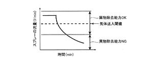
スプレーの流量は、流量計9で適宜確認すればよい。弁10を開放して気体を送入する際のスプレーの流量は、設備仕様によって適宜決めればよい。気体を送入する流量の閾値としては、図2に示すように、スプレーの最大流量と異物除去能力が不足する流量との間に設定することが好ましい。最大流量と異物除去能力が不足する流量との間に閾値を設定する理由は、気体送入頻度を極力減らし、かつ定常的に異物除去能力を満たすスプレー流量を確保するためである。また、異物除去能力を満たすスプレーの流量範囲については、個々の設備によって適宜決めれば良い。
The flow rate of the spray may be appropriately checked with the flow meter 9. The flow rate of the spray when the
なお、スプレーの流量が低下して配管内に気体を送入するのは、高度な表面品質を要求されない製品を製造する際に行えばよい。また、気体を送入する際において、ストレーナー11を通過する水の流量に変化を加えることはない。
Note that the flow rate of the spray is reduced and the gas is introduced into the pipe when the product that does not require high surface quality is manufactured. Further, when the gas is sent in, the flow rate of water passing through the
また、本発明では、ロール交換時などの未調圧状態のときに気体を送入してもよい。配管8内の汚れの蓄積が軽度な段階で配管内に気体を送入することができ、その結果、配管8内の汚れを除去することができる。
Further, in the present invention, the gas may be fed in when the pressure is not adjusted, such as when the roll is replaced. The gas can be fed into the
配管8内の汚れの除去という点から、気体を送入するのは、5分〜10分程度が好ましい。配管8内が気体によりバブリングされるため、配管8内の汚れをより一層除去することができる。
From the viewpoint of removing the dirt in the
以下に、本発明の実施例を説明する。 Examples of the present invention will be described below.
連続溶融亜鉛めっき鋼板製造ライン(CGL)において、亜鉛めっきを施した鋼板(板厚:0.60〜1.0mm、板幅:800〜1800mm)について、調質圧延を施した。 In a continuous hot-dip galvanized steel sheet production line (CGL), temper rolling was performed on a galvanized steel sheet (sheet thickness: 0.60 to 1.0 mm, sheet width: 800 to 1800 mm).
図1に示す調質圧延設備を用いて、調質圧延を行ったものを本発明例とした。スプレー流量については、通常時は70l/minとし、流量が50l/minを下回った場合に、弁10を開放して圧縮空気を送入した。圧縮空気の送入は10分間行った。
What was temper-rolled using the temper-rolling equipment shown in FIG. 1 was made into this invention example. The spray flow rate was usually 70 l/min, and when the flow rate was lower than 50 l/min, the
また、圧縮空気を送入しない従来の調質圧延設備で調質圧延を行ったものを比較例とした。 A comparative example was a case where temper rolling was performed using a conventional temper rolling facility that does not send compressed air.
本発明例および比較例によって得られた鋼板について、格落率(不良品の割合)を求めて比較を行った。具体的には、凸状のスキンパスロールピッチの押し疵欠陥の発生有無をCGL出側の目視検査により評価し、合否判定を実施した。その結果、格落率は圧縮空気を送入しない比較例に対して、本発明例では40%低減した。 With respect to the steel sheets obtained in the examples of the present invention and the comparative examples, the downgrading rate (ratio of defective products) was obtained and compared. Specifically, the presence/absence of occurrence of a flaw on the convex skin pass roll pitch was evaluated by a visual inspection on the CGL exit side, and a pass/fail judgment was made. As a result, the rating rate was reduced by 40% in the example of the present invention as compared with the comparative example in which compressed air was not fed.
1 調質圧延設備
2 上側ワークロール
3 下側ワークロール
4 上側バックアップロール
5 下側バックアップロール
6 スプレー
7 スプレー
8 配管
9 流量計
10 弁
11 ストレーナー
12 圧力計
S 鋼板
1 Temper rolling mill 2 Upper work roll 3 Lower work roll 4 Upper backup roll 5 Lower backup roll 6 Spray 7
Claims (1)
Priority Applications (1)
| Application Number | Priority Date | Filing Date | Title |
|---|---|---|---|
| JP2016178198A JP6743606B2 (en) | 2016-09-13 | 2016-09-13 | Cleaning method of temper rolling equipment for hot dip galvanized steel sheet |
Applications Claiming Priority (1)
| Application Number | Priority Date | Filing Date | Title |
|---|---|---|---|
| JP2016178198A JP6743606B2 (en) | 2016-09-13 | 2016-09-13 | Cleaning method of temper rolling equipment for hot dip galvanized steel sheet |
Publications (2)
| Publication Number | Publication Date |
|---|---|
| JP2018043254A JP2018043254A (en) | 2018-03-22 |
| JP6743606B2 true JP6743606B2 (en) | 2020-08-19 |
Family
ID=61692663
Family Applications (1)
| Application Number | Title | Priority Date | Filing Date |
|---|---|---|---|
| JP2016178198A Active JP6743606B2 (en) | 2016-09-13 | 2016-09-13 | Cleaning method of temper rolling equipment for hot dip galvanized steel sheet |
Country Status (1)
| Country | Link |
|---|---|
| JP (1) | JP6743606B2 (en) |
Families Citing this family (1)
| Publication number | Priority date | Publication date | Assignee | Title |
|---|---|---|---|---|
| CN110538879B (en) * | 2019-08-30 | 2020-10-30 | 攀钢集团攀枝花钢钒有限公司 | Control method for automatic roller washing of cold-rolled roller |
Family Cites Families (5)
| Publication number | Priority date | Publication date | Assignee | Title |
|---|---|---|---|---|
| JPS6122203U (en) * | 1984-07-09 | 1986-02-08 | 新日本製鐵株式会社 | hot rolling equipment |
| JPH0239601Y2 (en) * | 1984-11-02 | 1990-10-24 | ||
| JP2003062533A (en) * | 2001-08-24 | 2003-03-04 | Kimihiko Okanoe | Piping cleaning device |
| JP5131135B2 (en) * | 2008-02-26 | 2013-01-30 | 新日鐵住金株式会社 | Lubricant supply equipment, rolling mill, lubricant supply method and rolling method |
| JP2015167938A (en) * | 2014-03-10 | 2015-09-28 | 株式会社Screenホールディングス | Substrate processing device |
-
2016
- 2016-09-13 JP JP2016178198A patent/JP6743606B2/en active Active
Also Published As
| Publication number | Publication date |
|---|---|
| JP2018043254A (en) | 2018-03-22 |
Similar Documents
| Publication | Publication Date | Title |
|---|---|---|
| JP5433794B2 (en) | Rolling roll cleaning apparatus and cleaning method | |
| JP6743606B2 (en) | Cleaning method of temper rolling equipment for hot dip galvanized steel sheet | |
| JP2016185547A (en) | Draining device of metal strip and draining method of metal strip | |
| KR101903917B1 (en) | Cooling device for hot-dip plated steel sheet | |
| CN110496864B (en) | Cold rolling equipment and cold rolling treatment method | |
| JP5509648B2 (en) | Method and apparatus for draining hot-rolled steel sheet during threading | |
| WO2015144631A1 (en) | Device for the contact-free cleaning of rollers, and method therefor | |
| CN214719375U (en) | Online clearing device for roll mark defects of working roll of wet temper mill | |
| CN209020957U (en) | A kind of device improving the indentation of planisher foreign matter | |
| JP4370996B2 (en) | Descaling method and descaling equipment in hot rolling | |
| JPH0569028A (en) | Skin pass rolling mill | |
| US20200139416A1 (en) | Cleaning rolling stock during cold rolling of the rolling stock | |
| JP5223485B2 (en) | Strip cleaning method, manufacturing method, cleaning device, and continuous steel plate manufacturing facility | |
| JP4159028B2 (en) | Burner abnormality detection method for continuous annealing furnace | |
| US20140290704A1 (en) | Method and Device for Cleaning a Surface of a Steel Product | |
| JP5696456B2 (en) | Cooling method after rolling striped steel plate | |
| JP3858807B2 (en) | Cold tandem rolling mill | |
| JP2008126229A (en) | Continuous cold rolling equipment and its operating method | |
| CN211587981U (en) | Blowing device for preventing dust from being pressed into strip steel | |
| JP2019147165A (en) | Coiler front face purging equipment | |
| JP2004202677A (en) | On-line defect removing device and method for metal strip | |
| JP5974750B2 (en) | Descaling equipment | |
| KR101433459B1 (en) | Apparatus for supply of rolling oil | |
| JP3020864B2 (en) | Rolling equipment for stainless steel strip and method of rolling stainless steel strip | |
| JP4706113B2 (en) | Temper rolling method and hot-rolling equipment for hot-dip galvanized steel strip |
Legal Events
| Date | Code | Title | Description |
|---|---|---|---|
| A621 | Written request for application examination |
Free format text: JAPANESE INTERMEDIATE CODE: A621 Effective date: 20180419 |
|
| RD03 | Notification of appointment of power of attorney |
Free format text: JAPANESE INTERMEDIATE CODE: A7423 Effective date: 20180502 |
|
| RD04 | Notification of resignation of power of attorney |
Free format text: JAPANESE INTERMEDIATE CODE: A7424 Effective date: 20180509 |
|
| A977 | Report on retrieval |
Free format text: JAPANESE INTERMEDIATE CODE: A971007 Effective date: 20181017 |
|
| A131 | Notification of reasons for refusal |
Free format text: JAPANESE INTERMEDIATE CODE: A131 Effective date: 20181023 |
|
| A521 | Request for written amendment filed |
Free format text: JAPANESE INTERMEDIATE CODE: A523 Effective date: 20181213 |
|
| A131 | Notification of reasons for refusal |
Free format text: JAPANESE INTERMEDIATE CODE: A131 Effective date: 20190108 |
|
| RD04 | Notification of resignation of power of attorney |
Free format text: JAPANESE INTERMEDIATE CODE: A7424 Effective date: 20190327 |
|
| A131 | Notification of reasons for refusal |
Free format text: JAPANESE INTERMEDIATE CODE: A131 Effective date: 20190820 |
|
| A521 | Request for written amendment filed |
Free format text: JAPANESE INTERMEDIATE CODE: A523 Effective date: 20190910 |
|
| A02 | Decision of refusal |
Free format text: JAPANESE INTERMEDIATE CODE: A02 Effective date: 20200218 |
|
| RD13 | Notification of appointment of power of sub attorney |
Free format text: JAPANESE INTERMEDIATE CODE: A7433 Effective date: 20200402 |
|
| A521 | Request for written amendment filed |
Free format text: JAPANESE INTERMEDIATE CODE: A523 Effective date: 20200407 |
|
| A521 | Request for written amendment filed |
Free format text: JAPANESE INTERMEDIATE CODE: A821 Effective date: 20200402 |
|
| A911 | Transfer to examiner for re-examination before appeal (zenchi) |
Free format text: JAPANESE INTERMEDIATE CODE: A911 Effective date: 20200428 |
|
| TRDD | Decision of grant or rejection written | ||
| A01 | Written decision to grant a patent or to grant a registration (utility model) |
Free format text: JAPANESE INTERMEDIATE CODE: A01 Effective date: 20200630 |
|
| A61 | First payment of annual fees (during grant procedure) |
Free format text: JAPANESE INTERMEDIATE CODE: A61 Effective date: 20200713 |
|
| R150 | Certificate of patent or registration of utility model |
Ref document number: 6743606 Country of ref document: JP Free format text: JAPANESE INTERMEDIATE CODE: R150 |
|
| R250 | Receipt of annual fees |
Free format text: JAPANESE INTERMEDIATE CODE: R250 |