JP6742446B2 - Radio base station and control method thereof - Google Patents
Radio base station and control method thereof Download PDFInfo
- Publication number
- JP6742446B2 JP6742446B2 JP2018564629A JP2018564629A JP6742446B2 JP 6742446 B2 JP6742446 B2 JP 6742446B2 JP 2018564629 A JP2018564629 A JP 2018564629A JP 2018564629 A JP2018564629 A JP 2018564629A JP 6742446 B2 JP6742446 B2 JP 6742446B2
- Authority
- JP
- Japan
- Prior art keywords
- unit
- signal
- control
- base station
- notification
- Prior art date
- Legal status (The legal status is an assumption and is not a legal conclusion. Google has not performed a legal analysis and makes no representation as to the accuracy of the status listed.)
- Active
Links
Images


Classifications
-
- H—ELECTRICITY
- H04—ELECTRIC COMMUNICATION TECHNIQUE
- H04B—TRANSMISSION
- H04B7/00—Radio transmission systems, i.e. using radiation field
- H04B7/02—Diversity systems; Multi-antenna system, i.e. transmission or reception using multiple antennas
- H04B7/04—Diversity systems; Multi-antenna system, i.e. transmission or reception using multiple antennas using two or more spaced independent antennas
- H04B7/06—Diversity systems; Multi-antenna system, i.e. transmission or reception using multiple antennas using two or more spaced independent antennas at the transmitting station
- H04B7/0602—Diversity systems; Multi-antenna system, i.e. transmission or reception using multiple antennas using two or more spaced independent antennas at the transmitting station using antenna switching
-
- H—ELECTRICITY
- H04—ELECTRIC COMMUNICATION TECHNIQUE
- H04B—TRANSMISSION
- H04B7/00—Radio transmission systems, i.e. using radiation field
- H04B7/02—Diversity systems; Multi-antenna system, i.e. transmission or reception using multiple antennas
- H04B7/04—Diversity systems; Multi-antenna system, i.e. transmission or reception using multiple antennas using two or more spaced independent antennas
- H04B7/0413—MIMO systems
- H04B7/0426—Power distribution
-
- H—ELECTRICITY
- H04—ELECTRIC COMMUNICATION TECHNIQUE
- H04B—TRANSMISSION
- H04B7/00—Radio transmission systems, i.e. using radiation field
- H04B7/02—Diversity systems; Multi-antenna system, i.e. transmission or reception using multiple antennas
- H04B7/04—Diversity systems; Multi-antenna system, i.e. transmission or reception using multiple antennas using two or more spaced independent antennas
- H04B7/06—Diversity systems; Multi-antenna system, i.e. transmission or reception using multiple antennas using two or more spaced independent antennas at the transmitting station
- H04B7/0686—Hybrid systems, i.e. switching and simultaneous transmission
- H04B7/0691—Hybrid systems, i.e. switching and simultaneous transmission using subgroups of transmit antennas
- H04B7/0693—Hybrid systems, i.e. switching and simultaneous transmission using subgroups of transmit antennas switching off a diversity branch, e.g. to save power
-
- H—ELECTRICITY
- H04—ELECTRIC COMMUNICATION TECHNIQUE
- H04W—WIRELESS COMMUNICATION NETWORKS
- H04W16/00—Network planning, e.g. coverage or traffic planning tools; Network deployment, e.g. resource partitioning or cells structures
- H04W16/24—Cell structures
- H04W16/28—Cell structures using beam steering
-
- H—ELECTRICITY
- H04—ELECTRIC COMMUNICATION TECHNIQUE
- H04W—WIRELESS COMMUNICATION NETWORKS
- H04W52/00—Power management, e.g. TPC [Transmission Power Control], power saving or power classes
- H04W52/04—TPC
- H04W52/38—TPC being performed in particular situations
- H04W52/42—TPC being performed in particular situations in systems with time, space, frequency or polarisation diversity
-
- H—ELECTRICITY
- H04—ELECTRIC COMMUNICATION TECHNIQUE
- H04W—WIRELESS COMMUNICATION NETWORKS
- H04W68/00—User notification, e.g. alerting and paging, for incoming communication, change of service or the like
- H04W68/005—Transmission of information for alerting of incoming communication
-
- H—ELECTRICITY
- H04—ELECTRIC COMMUNICATION TECHNIQUE
- H04W—WIRELESS COMMUNICATION NETWORKS
- H04W72/00—Local resource management
- H04W72/20—Control channels or signalling for resource management
-
- H—ELECTRICITY
- H04—ELECTRIC COMMUNICATION TECHNIQUE
- H04W—WIRELESS COMMUNICATION NETWORKS
- H04W84/00—Network topologies
- H04W84/02—Hierarchically pre-organised networks, e.g. paging networks, cellular networks, WLAN [Wireless Local Area Network] or WLL [Wireless Local Loop]
- H04W84/10—Small scale networks; Flat hierarchical networks
- H04W84/12—WLAN [Wireless Local Area Networks]
-
- H—ELECTRICITY
- H04—ELECTRIC COMMUNICATION TECHNIQUE
- H04W—WIRELESS COMMUNICATION NETWORKS
- H04W88/00—Devices specially adapted for wireless communication networks, e.g. terminals, base stations or access point devices
- H04W88/08—Access point devices
-
- H—ELECTRICITY
- H04—ELECTRIC COMMUNICATION TECHNIQUE
- H04W—WIRELESS COMMUNICATION NETWORKS
- H04W72/00—Local resource management
- H04W72/04—Wireless resource allocation
- H04W72/044—Wireless resource allocation based on the type of the allocated resource
- H04W72/0453—Resources in frequency domain, e.g. a carrier in FDMA
Description
本発明は、分散アンテナを用いて1台以上の無線端末局と同一周波数チャネルを共有して無線通信を行う無線基地局において、アンテナの切替、各アンテナで送受信する信号の位相・タイミング・周波数・電力を所定の組み合わせで効率的に制御する無線基地局およびその制御方法に関する。 The present invention relates to a wireless base station that performs wireless communication by sharing the same frequency channel with one or more wireless terminal stations using distributed antennas, switching antennas, and phase/timing/frequency of signals transmitted/received by each antenna. The present invention relates to a wireless base station that efficiently controls power with a predetermined combination and a control method thereof.
近年、スマートフォン等の持ち運び可能で高性能な無線端末の普及により企業や公共スペースだけではなく、一般家庭でもIEEE802.11標準規格の無線LANが広く使われるようになっている。IEEE802.11標準規格の無線LANには、 2.4GHz帯を用いるIEEE802.11b/g/n 規格の無線LANと、5GHz帯を用いるIEEE802.11a/n/ac規格の無線LANがある。 In recent years, with the spread of portable and high-performance wireless terminals such as smartphones, the wireless LAN of the IEEE 802.11 standard has come to be widely used not only in companies and public spaces but also in general households. The wireless LAN of the IEEE802.11 standard includes a wireless LAN of the IEEE802.11b/g/n standard using the 2.4 GHz band and a wireless LAN of the IEEE802.11a/n/ac standard using the 5 GHz band.
IEEE802.11b規格やIEEE802.11g規格の無線LANでは、2400MHzから2483.5MHz間に5MHz間隔で13チャネルが用意されている。ただし、同一場所で複数のチャネルを使用する際には、干渉を避けるために、帯域が重ならないチャネルを使用する。その場合、最大で3チャネル、場合によっては4チャネルまで同時に使用できる。 In the wireless LAN of the IEEE802.11b standard or the IEEE802.11g standard, 13 channels are prepared at intervals of 5 MHz between 2400 MHz and 2483.5 MHz. However, when using multiple channels at the same location, use channels that do not overlap in band in order to avoid interference. In that case, up to 3 channels, and in some cases up to 4 channels can be used simultaneously.
IEEE802.11a規格の無線LANでは、日本の場合は、5170MHzから5330MHz間と、5490MHzから5710MHz間で、それぞれ互いに帯域が重ならない8チャネルおよび11チャネルの合計19チャネルが規定されている。なお、IEEE802.11a規格では、チャネル当たりの帯域幅が20MHzに固定されている。 In the wireless LAN of the IEEE802.11a standard, in the case of Japan, a total of 19 channels of 5 channels from 5170 MHz to 5330 MHz and 5 channels from 5490 MHz to 5710 MHz, which do not overlap each other, are specified. In the IEEE802.11a standard, the bandwidth per channel is fixed at 20 MHz.
無線LANの最大伝送速度は、IEEE802.11b規格の場合は11Mbps であり、IEEE802.11a規格やIEEE802.11g規格の場合は54Mbps である。ただし、ここでの伝送速度は物理レイヤ上での伝送速度である。実際にはMAC(Medium Access Control )レイヤでの伝送効率が50〜70%程度であるため、実際のスループットの上限値はIEEE802.11b規格では5Mbps 程度、IEEE802.11a規格やIEEE802.11g規格では30Mbps 程度である。また、伝送速度は、情報を送信しようとする無線局が増えればさらに低下する。 The maximum transmission rate of the wireless LAN is 11 Mbps in the case of the IEEE802.11b standard, and 54 Mbps in the case of the IEEE802.11a standard and the IEEE802.11g standard. However, the transmission rate here is the transmission rate on the physical layer. Actually, since the transmission efficiency in the MAC (Medium Access Control) layer is about 50 to 70%, the upper limit of the actual throughput is about 5 Mbps in the IEEE802.11b standard, and 30 Mbps in the IEEE802.11a standard and the IEEE802.11g standard. It is a degree. Further, the transmission rate further decreases as the number of wireless stations that transmit information increases.
そのため、2009年に標準化が完了したIEEE802.11n規格では、これまで20MHzと固定されていたチャネル帯域幅が最大で40MHzに拡大されるとともに、空間多重送信技術(MIMO:Multiple input multiple output)技術の導入が決定された。IEEE802.11n規格で規定されているすべての機能を適用して送受信を行うと、物理レイヤでは最大で 600Mbps の通信速度を実現可能である。 Therefore, in the IEEE 802.11n standard, which was standardized in 2009, the channel bandwidth, which was previously fixed at 20 MHz, was expanded to a maximum of 40 MHz, and spatial multiplexing transmission technology (MIMO: Multiple input multiple output) technology was used. The introduction was decided. If all functions defined in the IEEE 802.11n standard are applied for transmission/reception, a maximum communication speed of 600 Mbps can be realized in the physical layer.
さらに、2013年に標準化が完了したIEEE802.11ac規格では、チャネル帯域幅を80MHzや最大で 160MHzまで拡大することや、空間分割多元接続(SDMA:Space Division Multiple Access)を適用したマルチユーザMIMO(MU−MIMO)送信方法の導入が決定している。IEEE802.11ac規格で規定されているすべての機能を適用して送受信を行うと、物理レイヤでは最大で約 6.9Gbps の通信速度を実現可能である。 In addition, the IEEE802.11ac standard, which was standardized in 2013, expands the channel bandwidth to 80 MHz or a maximum of 160 MHz, and multi-user MIMO (MU) that applies space division multiple access (SDMA). -MIMO) transmission method has been decided to be introduced. If all the functions specified in the IEEE802.11ac standard are applied for transmission and reception, a maximum communication speed of approximately 6.9 Gbps can be realized in the physical layer.
このように無線LANでは、標準化規格の進化に伴い通信速度が改善されている。しかしながら、同一周波数チャネルを複数の無線局が共有する場合には、無線局数の増加に伴う通信機会の低下によってスループットが低下することが知られている。これに対して、無線局の送信電力を通信相手の状況に合わせて適応的に制御することで各無線局への干渉電力を抑圧し、結果として各無線局の通信機会を増加させる技術が検討されている(非特許文献1)。送信電力制御法の一例として、送信信号の振幅を可変抵抗器や可変増幅器などの電力調整装置を用いて制御する方法がある。 As described above, in the wireless LAN, the communication speed is improved with the evolution of the standard. However, when a plurality of wireless stations share the same frequency channel, it is known that throughput decreases due to a decrease in communication opportunities as the number of wireless stations increases. On the other hand, a technique to suppress the interference power to each wireless station by adaptively controlling the transmission power of the wireless station according to the situation of the communication partner and consequently increase the communication opportunity of each wireless station is considered. (Non-Patent Document 1). As an example of the transmission power control method, there is a method of controlling the amplitude of the transmission signal by using a power adjustment device such as a variable resistor or a variable amplifier.
図7は、本発明が想定する無線通信システムの構成例を示す。
図7において、ネットワーク30に接続される無線基地局10−1,10−2は同一の周波数チャネルを用いる構成であり、それぞれ配下の無線端末局20と無線通信を行う。また、無線基地局10−1,10−2はそれぞれ複数のアンテナを備え、1つまたは複数の無線端末局20とMIMO通信を行う構成になっている。さらに、無線基地局10−1,10−2は、宛先の無線端末局に応じて各アンテナの送受信電力を調整する機能も備えている。FIG. 7 shows a configuration example of a wireless communication system assumed by the present invention.
In FIG. 7, the wireless base stations 10-1 and 10-2 connected to the network 30 are configured to use the same frequency channel and perform wireless communication with the wireless terminal station 20 under their control. The radio base stations 10-1 and 10-2 each include a plurality of antennas and are configured to perform MIMO communication with one or a plurality of radio terminal stations 20. Furthermore, the wireless base stations 10-1 and 10-2 also have a function of adjusting the transmission/reception power of each antenna according to the destination wireless terminal station.
図8は、従来の無線基地局の構成例を示す。
図8において、無線基地局は、n個(nは2以上の整数)のアンテナ101−1〜101−nと、送信電力および受信電力を変更する電力変更部102−1〜102−nと、n本のアンテナで送受信する信号の送信処理および受信処理を行う送受信部103−1〜103−nと、無線基地局に接続するネットワークとの間で入出力する信号と各アンテナで送受信する信号との変換処理を行う信号処理制御部104と、送受信する信号の宛先無線端末局に応じた電力変更部102−1〜102−nの電力変更量を含む通知信号を出力する電力通知部105と、通知信号に応じて電力変更部102−1〜102−nの電力変更制御を行う電力制御部106とを備える。なお、電力通知部105は、信号処理制御部104内にある。FIG. 8 shows a configuration example of a conventional radio base station.
In FIG. 8, the radio base station includes n antennas 101-1 to 101-n (n is an integer of 2 or more), power changing units 102-1 to 102-n that change transmission power and reception power, Signals input/output between the transmission/reception units 103-1 to 103-n, which perform transmission processing and reception processing of signals transmitted/received by n antennas, and a signal transmitted/received by each antenna. A signal
電力通知部105は、送信処理を行う前に、事前設定された宛先無線端末局に対する各アンテナ対応の送信電力情報を抽出し、電力制御部106に対して各アンテナ対応の送信電力情報を通知する。電力制御部106は、電力通知部105からの通知信号に応じて、各アンテナ101−1〜101−nに対応する電力変更部102−1〜102−nで送信電力を変更する制御を行う。受信信号に対する受信電力の制御についても同様である。これにより、宛先無線端末局に対する最適な送信電力制御が行われるので、他の無線局への干渉電力を同時に抑圧し、無線通信システム全体の通信機会を増加させることが可能となり、スループットの向上が期待される。
Before performing the transmission process, the
さらに、送信電力の低減効果を高める技術として、無線基地局が有する複数のアンテナを分散配置することで、基地局アンテナと端末アンテナとの間の距離を縮め、結果的に各無線局の受信電力を増加させる分散アンテナ技術の検討も進んでいる(非特許文献2)。一方で、増加した受信電力を低減したとしても、従来と同様の通信品質を確保することが可能であることから、さらなる送信電力の低減も可能になっている。 Furthermore, as a technique for enhancing the effect of reducing the transmission power, a plurality of antennas included in the radio base station are dispersedly arranged to reduce the distance between the base station antenna and the terminal antenna, resulting in the reception power of each radio station. A study on a distributed antenna technology for increasing the number of antennas is also in progress (Non-Patent Document 2). On the other hand, even if the increased received power is reduced, it is possible to ensure the same communication quality as the conventional one, so that it is possible to further reduce the transmitted power.
図8に示す無線基地局の電力変更部102−1〜102−nは、電力制御部106によって、宛先無線端末局に応じてアンテナ101−1〜101−nで送受信する信号の電力が制御される。ここで、各アンテナ対応の電力変更量は、宛先無線端末局に応じて信号処理制御部104の電力通知部105で生成されて電力制御部106に通知される。この各アンテナ対応の電力変更量を通知する通知信号の伝送形態としては、次の2つの方法が考えられる。
In the power changing units 102-1 to 102-n of the wireless base station shown in FIG. 8, the
通知信号の第1の伝送形態は、図9の(1) に示すように、複数n本の制御線を用いて電力変更部102−1〜102−nを制御する電力変更用制御情報E1〜Enを並列に通知する。この場合には、電力通知部105から電力制御部106に対して短時間で電力変更用制御情報E1〜Enを通知でき、各アンテナで送受信する信号の電力変更を高速に実現することができる。しかし、複数n本の制御線が必要になるため、回路規模やコストの増加の課題がある。さらに、将来的に無線基地局のアンテナ数が大幅に増加した場合には、この課題を解決する必要がある。
The first transmission mode of the notification signal is, as shown in (1) of FIG. 9, the power change control information E1 to control the power change units 102-1 to 102-n using a plurality of n control lines. Notify En in parallel. In this case, the
通知信号の第2の伝送形態は、図9の(2) に示すように、1本の制御線を用いて電力変更部102−1〜102−nを制御する電力変更用制御情報E1〜Enを直列に通知する。この場合には、制御線の本数を1本にできるが、電力変更用制御情報E1〜Enのすべての通知にアンテナ数nに応じた時間がかかる。例えば、無線パケット単位で送信電力制御を行うには、ミリ秒単位以下の制御が必要になり、通知信号の伝送時間の短縮が課題となる。 The second transmission form of the notification signal is, as shown in (2) of FIG. 9, power change control information E1 to En for controlling the power change units 102-1 to 102-n using one control line. Are notified in series. In this case, the number of control lines can be set to one, but it takes time corresponding to the number of antennas n to notify all of the power change control information E1 to En. For example, in order to control the transmission power in units of wireless packets, control in milliseconds or less is necessary, and shortening the transmission time of the notification signal becomes an issue.
さらに、送信電力制御の効果をさらに高めることを目的として、分散アンテナを利用する場合には、分散アンテナを無線パケット単位で選択する構成が必要になる。この場合には、アンテナ切替部の追加が必要となり、このアンテナ切替部を制御するための制御信号も必要となる。したがって、各アンテナ対応の電力変更量とともに、アンテナ切替部の切替情報を効率よく通知するための技術が必要となる。 Furthermore, when a distributed antenna is used for the purpose of further enhancing the effect of transmission power control, it is necessary to select the distributed antenna in units of radio packets. In this case, an antenna switching unit needs to be added, and a control signal for controlling this antenna switching unit is also required. Therefore, a technique for efficiently notifying the switching information of the antenna switching unit together with the power change amount corresponding to each antenna is required.
また、さらなる通信品質の改善に向けて、各アンテナで送受信される信号の位相変更によって電波の指向性を制御するビームフォーミング技術の検討も進んでいる。ビームフォーミング技術を用いることで、対象となる方向の無線端末局の受信電力を大幅に低下させることなく、非対称の無線局に対して干渉を抑圧できることも注目されている。他にも、送受信のタイミング制御によって無線パケットの衝突を回避する技術や、アンテナ間の周波数同期の技術も検討されているため、将来的にはアンテナごとの位相・タイミング・周波数についても制御対象となる可能性が高い。しかしながら、これらの変更部を制御するためには、効率的な制御情報の通知が必須となる。 In addition, in order to further improve the communication quality, a beamforming technique for controlling the directivity of radio waves by changing the phase of signals transmitted and received by each antenna is being studied. It is also noted that by using the beamforming technology, interference can be suppressed for asymmetric wireless stations without significantly reducing the received power of the wireless terminal stations in the target direction. In addition, technologies for avoiding collisions of wireless packets by controlling transmission/reception timing and technologies for frequency synchronization between antennas are being studied, so in the future, the phase, timing, and frequency of each antenna will also be controlled. Is likely to be. However, in order to control these changing units, efficient notification of control information is essential.
また、アンテナ切替部、アンテナごとの位相・タイミング・周波数・電力を変更する各変更部は、それぞれ切替/変更動作の開始から終了までの反応時間が異なる可能性が高いことから、各部の反応時間も考慮した制御が必要となる。 In addition, the antenna switching unit and each changing unit that changes the phase, timing, frequency, and power for each antenna are likely to have different reaction times from the start to the end of the switching/changing operation. It is also necessary to take control into consideration.
本発明は、アンテナ切替部および信号変更部の位相・タイミング・周波数・電力の各変更部の反応時間を考慮し、複数のアンテナで送受信する信号の切替/変更制御を高速に行うことができる無線基地局およびその制御方法を提供することを目的とする。 The present invention considers the reaction time of each phase/timing/frequency/power changing section of an antenna switching section and a signal changing section, and enables high-speed wireless switching/changing control of signals transmitted/received by a plurality of antennas. An object is to provide a base station and a control method thereof.
第1の発明は、無線基地局と1台以上の無線端末局が同一周波数チャネルを共有する無線通信システムの無線基地局において、1セット複数本のアンテナがnセット(nは2以上の整数)のアンテナセットと、アンテナセットごとに1本のアンテナを選択するn個のアンテナ切替部と、アンテナ切替部でアンテナセットごとに選択されたn本のアンテナで送受信する信号の位相・タイミング・周波数・電力を1以上の組み合わせで変更するn個の信号変更部と、n本のアンテナで送受信する信号の宛先無線端末局に応じたアンテナ切替部および信号変更部の制御情報を、アンテナ切替部の切替時間および信号変更部の各変更時間(各部の反応時間)に応じて配列した通知信号を出力する通知部と、通知信号の各部の制御情報が通知された順に、アンテナ切替部の切替制御および信号変更部の各変更制御を逐次開始する制御部とを備える。 A first invention is a wireless base station of a wireless communication system in which a wireless base station and one or more wireless terminal stations share the same frequency channel, and one set of a plurality of antennas is n sets (n is an integer of 2 or more). Antenna set, n antenna switching units that select one antenna for each antenna set, and phase, timing, and frequency of signals transmitted and received by the n antennas selected for each antenna set by the antenna switching unit. N signal changing units for changing the power in a combination of 1 or more, and the antenna switching unit and the control information of the signal changing unit according to the destination wireless terminal station of the signals transmitted and received by the n antennas are switched by the antenna switching unit. A notification unit that outputs a notification signal arranged according to each change time (reaction time of each unit) of the time and signal change unit, and switching control and signal of the antenna switching unit in the order in which the control information of each unit of the notification signal is notified. And a control unit that sequentially starts each change control of the change unit.
第1の発明の無線基地局において、通知部は、通知信号の各部の制御情報を、各部の反応時間の大きい順に配列する構成である。 In the wireless base station according to the first aspect of the present invention, the notification unit has a configuration in which the control information of each unit of the notification signal is arranged in descending order of reaction time of each unit.
第1の発明の無線基地局において、通知部は、通知信号の各部の制御情報を、アンテナ切替部の切替制御および信号変更部の各変更制御が指定時間内に終了する配列とする構成である。 In the radio base station according to the first aspect of the present invention, the notification unit is configured such that the control information of each unit of the notification signal is an array in which the switching control of the antenna switching unit and the change control of the signal changing unit are completed within a specified time. ..
第1の発明の無線基地局において、通知部は、通知信号の各部の制御情報の情報量を削減する構成であり、制御部、アンテナ切替部および信号変更部は、削減された情報量の制御情報に対応する切替制御および各変更制御を行う構成である。 In the radio base station of the first aspect of the invention, the notification unit is configured to reduce the information amount of the control information of each unit of the notification signal, and the control unit, the antenna switching unit and the signal change unit control the reduced information amount. This is a configuration for performing switching control and each change control corresponding to information.
第1の発明の無線基地局において、信号変更部の位相・タイミング・周波数・電力の少なくとも1つの変更部は、反応時間が異なる複数のデバイスを多段構成し、通知部は、通知信号の各部の制御情報を、反応時間の長いデバイスの制御情報から順に配列する構成である。 In the radio base station according to the first aspect of the invention, at least one of the phase/timing/frequency/power changing unit of the signal changing unit is configured with a plurality of devices having different reaction times in multiple stages, and the notification unit is The control information is arranged in order from the control information of the device having a long reaction time.
第2の発明は、第1の発明の無線基地局の制御方法において、無線基地局が外部のネットワークから入力する信号の宛先無線端末局を抽出し、宛先無線端末局に応じた信号形式、アンテナ切替部で切り替えるアンテナ、信号変更部の位相・タイミング・周波数・電力の各変更部の変更量からなる制御情報を決定するステップと、通知部は、宛先無線端末局に対応する各部の制御情報を各部の反応時間に応じて配列した通知信号を生成し、制御部に送信するステップと、制御部は、通知信号の各部に対する制御情報の到着と同時に、アンテナ切替部の切替制御および信号変更部の変更制御を開始するステップとを有し、アンテナ切替部および信号変更部の制御完了後に信号を送受信する。 A second invention is the method of controlling a wireless base station according to the first invention, wherein the wireless base station extracts a destination wireless terminal station of a signal input from an external network, and a signal format and an antenna corresponding to the destination wireless terminal station are extracted. The step of determining the control information consisting of the amount of change of each phase/timing/frequency/power change section of the antenna and signal change section of the change section, and the notification section, the control information of each section corresponding to the destination wireless terminal station. The step of generating a notification signal arranged according to the reaction time of each part and transmitting it to the control part, and the control part, when the control information arrives at each part of the notification signal, simultaneously with the switching control of the antenna switching part and the signal changing part. Changing control is started, and a signal is transmitted and received after control of the antenna switching unit and the signal changing unit is completed.
第2の発明の無線基地局の制御方法において、通知部は、通知信号の各部の制御情報を、各部の反応時間の大きい順に配置する。 In the wireless base station control method of the second invention, the notification unit arranges the control information of each unit of the notification signal in the descending order of reaction time of each unit.
第2の発明の無線基地局の制御方法において、通知部は、通知信号の各部の制御情報を、アンテナ切替部の切替制御および信号変更部の各変更制御が指定時間内に終了する配列とする。 In the radio base station control method according to the second aspect of the present invention, the notification unit sets the control information of each unit of the notification signal to an array in which the switching control of the antenna switching unit and the change control of the signal changing unit are completed within a specified time. ..
本発明は、アンテナ切替部および信号変更部の位相・タイミング・周波数・電力の各変更部の反応時間に応じた通知信号を構成し、切替/変更の各制御情報の到着と同時に制御を開始することにより、複数のアンテナで送受信する信号の切替/変更処理を高速に行うことができ、高速信号にも対応することができる。 The present invention configures a notification signal according to the reaction time of each phase/timing/frequency/power modification unit of the antenna switching unit and signal modification unit, and starts control at the same time when each control information for switching/modification arrives. As a result, switching/changing processing of signals transmitted/received by a plurality of antennas can be performed at high speed, and high-speed signals can be handled.
図1は、本発明の無線基地局の構成例を示す。
図1において、無線基地局のアンテナセット11−1〜11−nは、1セット複数本のアンテナがnセット(nは2以上の整数)からなる。アンテナ切替部12−1〜12−nは、アンテナセットごとに1本のアンテナを選択し、全体でn本のアンテナを選択する。信号変更部13−1〜13−nは、アンテナセットごとに選択されたn本のアンテナで送受信する信号の位相・タイミング・周波数・電力を変更する。送受信部14−1〜14−nは、n本のアンテナで送受信する信号の送信処理および受信処理を行う。信号処理制御部15は、無線基地局に接続するネットワークとの間で入出力する信号と各アンテナで送受信する信号との変換処理を行う。通知部16は、送受信する信号の宛先無線端末局に応じたアンテナ切替部12−1〜12−nおよび信号変更部13−1〜13−nの制御情報を含む通知信号を出力する。制御部17は、通知信号に応じてアンテナ切替部12−1〜12−nの切替処理および信号変更部13−1〜13−nの変更処理を制御する。
なお、アンテナセット11−1〜11−nの各アンテナは、分散配置されてもよい。また、アンテナごとに異なる指向性を有する構成でもよい。FIG. 1 shows a configuration example of a radio base station of the present invention.
In FIG. 1, each of the antenna sets 11-1 to 11-n of the radio base station includes one set of a plurality of antennas (n sets (n is an integer of 2 or more)). The antenna switching units 12-1 to 12-n select one antenna for each antenna set, and select n antennas as a whole. The signal changing units 13-1 to 13-n change the phase/timing/frequency/power of the signals transmitted/received by the n antennas selected for each antenna set. The transmission/reception units 14-1 to 14-n perform transmission processing and reception processing of signals transmitted/received by n antennas. The signal
The antennas of the antenna sets 11-1 to 11-n may be distributed and arranged. Also, a configuration may be used in which each antenna has a different directivity.
信号変更部13−1〜13−nを構成する位相・タイミング・周波数・電力の各変更部は、宛先無線端末局に応じてすべてまたは一部が変更対象となり、通知信号の制御情報は各変更部の中から変更対象となる組み合わせに応じて構成される。また、各変更部は変更動作の開始から終了までの反応時間がそれぞれ異なり、さらに各変更部はそれぞれ反応時間の異なる複数のデバイスを多段接続する構成であってもよい。 All or some of the phase/timing/frequency/power changing units constituting the signal changing units 13-1 to 13-n are subject to change depending on the destination wireless terminal station, and the control information of the notification signal is changed. It is configured according to the combination to be changed from among the parts. Further, each change unit may have a different reaction time from the start to the end of the change operation, and each change unit may have a configuration in which a plurality of devices having different reaction times are connected in multiple stages.
図2は、本発明の無線基地局の信号送信手順を示す。
図2において、信号処理制御部15は、外部のネットワークから宛先無線端末局に送信する信号を入力すると(S11)、当該送信信号の宛先無線端末局を抽出し、宛先無線端末局に応じた信号形式、アンテナ切替部12−1〜12−nでそれぞれ切り替えるアンテナ、信号変更部13−1〜13−nの各変更部の変更量を決定し、通知部16に通知する(S12)。これらの情報は、信号処理制御部15が宛先無線端末局に対応付けて保持しているか、ネットワークに接続される外部制御装置から通知部16に直接通知される構成でもよい。FIG. 2 shows a signal transmission procedure of the radio base station of the present invention.
In FIG. 2, when the signal
ここで、宛先無線端末局に応じた信号形式は、アンテナ切替部12−1〜12−nで切り替えたn本のアンテナで送受信する信号として、1つの宛先無線端末局に対応するSU−MIMO信号、複数の宛先無線端末局に対応するMU−MIMO信号またはマルチキャスト信号などに対応するものである。 Here, the signal format corresponding to the destination wireless terminal station is a SU-MIMO signal corresponding to one destination wireless terminal station as a signal transmitted and received by n antennas switched by the antenna switching units 12-1 to 12-n. , MU-MIMO signals or multicast signals corresponding to a plurality of destination wireless terminal stations.
通知部16は、宛先無線端末局に対応する各部の切替/変更の制御情報を各部の反応時間に応じて配列した通知信号を生成し、制御部17に送信する(S13)。制御部17は、通知信号の各部に対する制御情報の到着と同時に、アンテナ切替部12−1〜12−nの切替および信号変更部13−1〜13−nの各変更のための制御を開始する(S14)。アンテナ切替部12−1〜12−nおよび信号変更部13−1〜13−nの制御完了後に信号を送信する(S15)。
The
本発明の無線基地局の信号受信手順は、信号処理制御部15および通知部16が信号送信の終了後に各部の受信用の変更量を制御情報として決定した後は、信号送信手順と同様である。宛先無線端末局に対応する各部の制御情報を各部の反応時間に応じて配列した通知信号を生成して制御部17に送信し、制御部17が通知信号の各部に対する制御情報の到着と同時に、アンテナ切替部12−1〜12−nの切替および信号変更部13−1〜13−nの各変更のための制御を開始し、その制御完了後に信号の受信待機となり、受信する手順となる。
The signal receiving procedure of the radio base station of the present invention is the same as the signal transmitting procedure after the signal
なお、信号送信の終了タイミングは、通知部16から制御部17に通知されるが、通知部16または制御部17が送受信部14−1〜14−nからアンテナ切替部12−1〜12−nを信号が通過するまでの時間が考慮される。
The
本発明は、アンテナ切替部12−1−12−nおよび信号変更部13−1〜13−nの各変更部の反応時間を考慮し、信号の送受信が可能になる各部の制御終了までの時間短縮がポイントであり、その詳細について以下に説明する。 The present invention considers the reaction time of each change unit of the antenna switching unit 12-1-12-n and the signal change units 13-1 to 13-n, and the time until the end of control of each unit that enables transmission and reception of signals. The point is shortening, and the details will be described below.
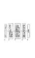
図3は、本発明における通知信号の構成例1を示す。
図3において、通知部16から制御部17に送信される通知信号は、アンテナ切替部12−1〜12−nに対するアンテナ切替用制御情報A1〜An、信号変更部13−1〜13−nに対する位相変更用制御情報B1〜Bn、タイミング変更用制御情報C1〜Cn、周波数変更用制御情報D1〜Dn、電力変更用制御情報E1〜Enが時間軸上に配置される。ここでは、通知部16から制御部17に対して1本の信号線を用いて、アンテナ切替と、各アンテナで送受信する信号の位相・タイミング・周波数・電力を一括して変更する制御情報を含む通知信号の構成例を示すが、位相・タイミング・周波数・電力のうち変更する組み合わせに応じた制御情報からなる通知信号であってもよい。FIG. 3 shows a configuration example 1 of the notification signal in the present invention.
In FIG. 3, the notification signal transmitted from the
制御部17は、この通知信号が到着すると、アンテナ切替部12−1〜12−nおよび信号変更部13−1〜13−nの各変更部の制御情報に分解してそれぞれに送出する。その制御情報に対するアンテナ切替部12−1〜12−nの反応時間をt1、信号変更部13−1〜13−nの位相・タイミング・周波数・電力の各変更部の反応時間をt2〜t5とし、例えば
t1<t5<t2<t3<t4
の関係にあるものとする。すなわち、図3の(1) の参考例に示すように、制御部17に通知信号の全部が到着してからアンテナ切替部12−1〜12−nの切替および信号変更部13−1〜13−nの変更を一斉に開始すると、最長の周波数変更の反応時間t4後に信号の送受信が可能となる。When the notification signal arrives, the
Have a relationship of That is, as shown in the reference example of (1) of FIG. 3, the switching of the antenna switching units 12-1 to 12-n and the signal changing units 13-1 to 13-13 after all the notification signals arrive at the
本発明の第1の特徴は、図3の(2) に示すように、制御部17が通知信号の各部の制御情報が通知されると同時に、アンテナ切替部12−1〜12−nの切替制御および信号変更部13−1〜13−nの各変更制御を逐次開始するところにある。これにより、反応時間が最長の周波数変更のための制御情報D1〜Dnが通知信号の最後にならない限り、全体の切替/変更終了を早めて信号の送受信開始を早めることができる。
The first feature of the present invention is that, as shown in (2) of FIG. 3, the
本発明の第2の特徴は、図3の(3) に示すように、通知部16は各部に対する制御情報が反応時間の長い順に配列された通知信号を生成するところにある。これにより、反応時間が最短のアンテナ切替のための制御情報A1〜Anが最後になるので、全体の変更完了を確実に早めて信号の送受信開始を早めることができる。
The second feature of the present invention is that, as shown in (3) of FIG. 3, the
なお、図3に示す例では、アンテナ切替部12−1〜12−nの切替および信号変更部13−1〜13−nの各変更のための制御開始は、全アンテナに対応するn個すべての制御情報が到着してから一斉に動作開始していた。一方、各アンテナの制御情報ごとに各部の制御動作を開始させてもよい。例えば、アンテナ切替部12−1〜12−nが制御情報A1〜Anに対して一斉に切替制御を開始してもよく、またアンテナ切替部12−1が制御情報A1に対して切替制御を開始し、以下順次切替制御を開始してもよい。 In the example shown in FIG. 3, the control start for switching the antenna switching units 12-1 to 12-n and each change of the signal changing units 13-1 to 13-n is performed for all n antennas corresponding to all the antennas. The control information has arrived and all of them have started operating at once. On the other hand, the control operation of each unit may be started for each control information of each antenna. For example, the antenna switching units 12-1 to 12-n may simultaneously start switching control for the control information A1 to An, or the antenna switching unit 12-1 starts switching control to the control information A1. However, the switching control may be sequentially started below.
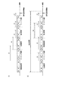
図4は、本発明における通知信号の構成例2を示す。
図4の(1) は、比較のために図3の(3) の例を示す。
図4の(2) において、通知部16は、アンテナ切替部12−1〜12−nおよび信号変更部13−1〜13−nの各部が全体として指定時間内に制御終了するように配列した通知信号を生成する。すなわち、通知部16は、各部が指定時間内に制御終了する通知信号の組み合わせの中から1つを選択すればよく、最初に見つかった通知信号の組み合わせが指定時間内完了の条件を満たせばそれでよい(First fit )。よって、図4の(1) に示すように、反応時間が最長の周波数変更のための制御情報D1〜Dnが通知信号の最初に限定されるものではなく、また反応時間が最短のアンテナ切替のための制御情報A1〜Anが最後に限定されるものではない。FIG. 4 shows a configuration example 2 of the notification signal in the present invention.
FIG. 4(1) shows an example of FIG. 3(3) for comparison.
In (2) of FIG. 4, the
図5は、本発明における通知信号の構成例3を示す。
図5の(1) は、比較のために図3の(3) の例を示す。
図5の(2) において、アンテナ切替部12−1〜12−nおよび信号変更部13−1〜13−nの各変更部の制御範囲や分解能を限定して制御情報を短縮し、全体の切替/変更にかかる時間を短縮してもよい。ここでは、アンテナ切替用制御情報A1〜An以外の各変更用制御情報の全てが短縮されているが、その一部であってもよい。また、アンテナ切替用制御情報A1〜Anについては、切り替えるアンテナ数の削減によって制御情報を短縮してもよい。また、図4に示す指定時間が短い場合にも、各制御情報を短縮することにより対応可能となる。FIG. 5 shows a configuration example 3 of the notification signal according to the present invention.
FIG. 5(1) shows the example of FIG. 3(3) for comparison.
In (2) of FIG. 5, the control information and the control information are shortened by limiting the control range and resolution of each change unit of the antenna switching units 12-1 to 12-n and the signal change units 13-1 to 13-n. The time required for switching/changing may be shortened. Here, all of the change control information other than the antenna switching control information A1 to An is shortened, but it may be a part thereof. As for the antenna switching control information A1 to An, the control information may be shortened by reducing the number of antennas to be switched. Further, even when the designated time shown in FIG. 4 is short, it can be dealt with by shortening each control information.
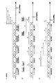
図6は、本発明における通知信号の構成例4を示す。
ここでは、信号変更部13−1〜13−nの各変更部がそれぞれ反応時間の異なる複数のデバイスを多段接続した構成を想定し、図6では2段構成の周波数変更部に対応する通知信号の構成例を示す。FIG. 6 shows a configuration example 4 of the notification signal according to the present invention.
Here, it is assumed that each changing unit of the signal changing units 13-1 to 13-n has a plurality of devices having different reaction times connected in multiple stages, and in FIG. 6, a notification signal corresponding to the frequency changing unit having a two-stage configuration is provided. A configuration example of is shown.
図6において、周波数変更部の第1段デバイスの制御情報をD1−1〜Dn−1、第2段デバイスの制御情報をD1−2〜Dn−2とし、第1段デバイスの反応時間t4−1が第2段デバイスの反応時間t4−2よりも長いとする。信号変更部13−1〜13−nの各周波数変更部に対して、第1段デバイスと第2段デバイスの制御情報Di−1,Di−2をセットで配置するより、各周波数変更部の反応時間の長い第1段デバイスの制御情報D1−1〜Dn−1を先頭に配置し、その到着後に第1段デバイスの周波数変更を開始する方が、全体の周波数変更終了の時間を早めることができる。 In FIG. 6, the control information of the first-stage device of the frequency changing unit is D1-1 to Dn-1, the control information of the second-stage device is D1-2 to Dn-2, and the reaction time t4- of the first-stage device is 1 is longer than the reaction time t4-2 of the second stage device. By arranging the control information Di-1 and Di-2 of the first stage device and the second stage device as a set for each frequency changing unit of the signal changing units 13-1 to 13-n, It is preferable to place the control information D1-1 to Dn-1 of the first-stage device having a long reaction time at the head and start the frequency change of the first-stage device after the arrival of the control information D1-1 to speed up the end time of the entire frequency change. You can
また、以上示した各通知信号の構成例において、通信信号の最後に、パリティチェックビットやフレームチェックシーケンスなどの検査用ビットを配置してもよい。以上示した各通知信号は、制御部17において、アンテナ切替部12−1〜12−nおよび信号変更部13−1〜13−nの各変更部のn個の制御情報が到着した時点で、切替または変更制御を開始することを想定しているが、検査用ビットで通知信号の誤りが検出された場合には、先行開始している切替または変更制御をリセットしてもよい。
Further, in the configuration example of each notification signal described above, a check bit such as a parity check bit or a frame check sequence may be arranged at the end of the communication signal. Each notification signal shown above is, when the
10 無線基地局
11 アンテナセット
12 アンテナ切替部
13 信号変更部
14 送受信部
15 信号処理制御部
16 通知部
17 制御部
20 無線端末局
30 ネットワーク
101 アンテナ
102 電力変更部
103 送受信部
104 信号処理制御部
105 電力通知部
106 電力制御部10
Claims (8)
1セット複数本のアンテナがnセット(nは2以上の整数)のアンテナセットと、
前記アンテナセットごとに1本のアンテナを選択するn個のアンテナ切替部と、
前記アンテナ切替部で前記アンテナセットごとに選択されたn本のアンテナで送受信する信号の位相・タイミング・周波数・電力を1以上の組み合わせで変更するn個の信号変更部と、
前記n本のアンテナで送受信する信号の宛先無線端末局に応じた前記アンテナ切替部および前記信号変更部の制御情報を、前記アンテナ切替部の切替時間および前記信号変更部の各変更時間(以下、「各部の反応時間」という)に応じて配列した通知信号を出力する通知部と、
前記通知信号の各部の制御情報が通知された順に、前記アンテナ切替部の切替制御および前記信号変更部の各変更制御を逐次開始する制御部と
を備えたことを特徴とする無線基地局。In a wireless base station of a wireless communication system in which a wireless base station and one or more wireless terminal stations share the same frequency channel,
An antenna set in which one set includes a plurality of antennas (n is an integer of 2 or more), and
N antenna switching units that select one antenna for each antenna set,
N signal changing units that change the phase, timing, frequency, and power of the signals transmitted and received by the n antennas selected by the antenna switching unit for each antenna set in one or more combinations;
The control information of the antenna switching unit and the signal changing unit according to the destination wireless terminal station of the signal transmitted and received by the n antennas is set to the switching time of the antenna switching unit and each change time of the signal changing unit (hereinafter, A notification unit that outputs a notification signal arranged according to "the reaction time of each part",
A radio base station, comprising: a control unit that sequentially starts switching control of the antenna switching unit and each change control of the signal changing unit in the order in which the control information of each unit of the notification signal is notified.
前記通知部は、前記通知信号の各部の制御情報を、前記各部の反応時間の大きい順に配列する構成である
ことを特徴とする無線基地局。The radio base station according to claim 1,
The said notification part is a structure which arranges the control information of each part of the said notification signal in descending order of reaction time of each said part. The radio base station characterized by the above-mentioned.
前記通知部は、前記通知信号の各部の制御情報を、前記アンテナ切替部の切替制御および前記信号変更部の各変更制御が指定時間内に終了する配列とする構成である
ことを特徴とする無線基地局。The radio base station according to claim 1,
The notification unit is configured such that the control information of each unit of the notification signal is an array in which switching control of the antenna switching unit and each change control of the signal changing unit is completed within a designated time. base station.
前記通知部は、前記通知信号の各部の制御情報の情報量を削減する構成であり、
前記制御部、前記アンテナ切替部および前記信号変更部は、前記削減された情報量の制御情報に対応する切替制御および各変更制御を行う構成である
ことを特徴とする無線基地局。The radio base station according to claim 1,
The notification unit is configured to reduce the amount of control information of each unit of the notification signal,
The radio base station, wherein the control unit, the antenna switching unit, and the signal changing unit are configured to perform switching control and each change control corresponding to the control information of the reduced information amount.
前記信号変更部の位相・タイミング・周波数・電力の少なくとも1つの変更部は、前記反応時間が異なる複数のデバイスを多段構成し、
前記通知部は、前記通知信号の各部の制御情報を、前記反応時間の長いデバイスの制御情報から順に配置する構成である
ことを特徴とする無線基地局。The radio base station according to claim 1,
At least one of the phase/timing/frequency/power changing unit of the signal changing unit is a multi-stage configuration of a plurality of devices having different reaction times,
The radio base station, wherein the notification unit is configured to arrange the control information of each unit of the notification signal in order from the control information of the device having the long reaction time.
前記無線基地局が外部のネットワークから入力する信号の宛先無線端末局を抽出し、宛先無線端末局に応じた信号形式、前記アンテナ切替部で切り替えるアンテナ、前記信号変更部の位相・タイミング・周波数・電力の各変更部の変更量からなる制御情報を決定するステップと、
前記通知部は、前記宛先無線端末局に対応する各部の制御情報を各部の反応時間に応じて配列した通知信号を生成し、前記制御部に送信するステップと、
前記制御部は、前記通知信号の各部に対する制御情報の到着と同時に、前記アンテナ切替部の切替制御および前記信号変更部の変更制御を開始するステップと
を有し、前記アンテナ切替部および前記信号変更部の制御完了後に信号を送受信することを特徴とする無線基地局の制御方法。The method for controlling a radio base station according to claim 1,
The wireless base station extracts a destination wireless terminal station of a signal input from an external network, a signal format corresponding to the destination wireless terminal station, an antenna switched by the antenna switching unit, a phase/timing/frequency of the signal changing unit. Determining control information consisting of the amount of change of each change part of power,
The notification unit generates a notification signal in which control information of each unit corresponding to the destination wireless terminal station is arranged according to a reaction time of each unit, and transmits the notification signal to the control unit,
The control unit starts switching control of the antenna switching unit and change control of the signal changing unit at the same time when control information for each unit of the notification signal arrives, and the antenna switching unit and the signal changing unit A method of controlling a radio base station, comprising transmitting and receiving a signal after the control of the unit is completed.
前記通知部は、前記通知信号の各部の制御情報を、前記各部の反応時間の大きい順に配列する
ことを特徴とする無線基地局の制御方法。The method for controlling a radio base station according to claim 6,
The control method of a radio base station, wherein the notification section arranges the control information of each section of the notification signal in the descending order of reaction time of each section.
前記通知部は、前記通知信号の各部の制御情報を、前記アンテナ切替部の切替制御および前記信号変更部の各変更制御が指定時間内に終了する配列とする
ことを特徴とする無線基地局の制御方法。The method for controlling a radio base station according to claim 6,
The notifying unit sets the control information of each unit of the notification signal as an array in which switching control of the antenna switching unit and each change control of the signal changing unit is completed within a specified time. Control method.
Applications Claiming Priority (3)
| Application Number | Priority Date | Filing Date | Title |
|---|---|---|---|
| JP2017013222 | 2017-01-27 | ||
| JP2017013222 | 2017-01-27 | ||
| PCT/JP2018/002295 WO2018139539A1 (en) | 2017-01-27 | 2018-01-25 | Wireless base station and method for controlling same |
Publications (2)
| Publication Number | Publication Date |
|---|---|
| JPWO2018139539A1 JPWO2018139539A1 (en) | 2019-12-19 |
| JP6742446B2 true JP6742446B2 (en) | 2020-08-19 |
Family
ID=62978391
Family Applications (1)
| Application Number | Title | Priority Date | Filing Date |
|---|---|---|---|
| JP2018564629A Active JP6742446B2 (en) | 2017-01-27 | 2018-01-25 | Radio base station and control method thereof |
Country Status (7)
| Country | Link |
|---|---|
| US (1) | US11005545B2 (en) |
| EP (1) | EP3576313B1 (en) |
| JP (1) | JP6742446B2 (en) |
| KR (1) | KR102236797B1 (en) |
| CN (1) | CN110268639B (en) |
| TW (1) | TWI646790B (en) |
| WO (1) | WO2018139539A1 (en) |
Families Citing this family (2)
| Publication number | Priority date | Publication date | Assignee | Title |
|---|---|---|---|---|
| US10334085B2 (en) * | 2015-01-29 | 2019-06-25 | Splunk Inc. | Facilitating custom content extraction from network packets |
| CN109474964A (en) * | 2018-11-21 | 2019-03-15 | Tcl移动通信科技(宁波)有限公司 | Mobile terminal LTE Frequency Band Selection processing method, mobile terminal and storage medium |
Family Cites Families (20)
| Publication number | Priority date | Publication date | Assignee | Title |
|---|---|---|---|---|
| WO2002025859A1 (en) * | 2000-09-12 | 2002-03-28 | Kvaser Consultant Ab | An arrangement with a number of units that can communicate with each other via a wireless connection system and a method for use with such a system |
| CN1225849C (en) * | 2003-07-18 | 2005-11-02 | 大唐移动通信设备有限公司 | Method and device for proceeding bidirectional synchronous translate against radio signal |
| JP2005341531A (en) * | 2004-04-27 | 2005-12-08 | Matsushita Electric Ind Co Ltd | Wireless communications system and radio station |
| US7826807B2 (en) * | 2005-03-09 | 2010-11-02 | Qualcomm Incorporated | Methods and apparatus for antenna control in a wireless terminal |
| JP2007295253A (en) * | 2006-04-25 | 2007-11-08 | Fujitsu Ten Ltd | Reception control device and switching control method |
| ES2356858T3 (en) * | 2006-08-07 | 2011-04-13 | Qualcomm Incorporated | MESSAGE EXCHANGE SCHEME FOR ASynchronous WIRELESS COMMUNICATIONS. |
| US8107915B2 (en) * | 2008-04-28 | 2012-01-31 | Delphi Technologies, Inc. | Receiver system and method for receiving signals |
| US20100304773A1 (en) * | 2009-05-27 | 2010-12-02 | Ramprashad Sean A | Method for selective antenna activation and per antenna or antenna group power assignments in cooperative signaling wireless mimo systems |
| CN102340860B (en) * | 2010-07-27 | 2014-04-02 | 杭州华三通信技术有限公司 | Power control method and device for intelligent antenna system |
| EP2624478B1 (en) * | 2010-09-30 | 2022-07-20 | Panasonic Holdings Corporation | Radio communication device |
| JP5289486B2 (en) * | 2011-03-08 | 2013-09-11 | 株式会社東芝 | Radio base station apparatus, radio unit control apparatus, and radio communication method |
| US20120274154A1 (en) * | 2011-04-27 | 2012-11-01 | Research In Motion Limited | Methods and apparatuses for wireless power transfer |
| JP2015008363A (en) * | 2013-06-24 | 2015-01-15 | 株式会社東芝 | Distributed antenna system, management control device, management control device control method and control program |
| KR101835669B1 (en) * | 2013-09-11 | 2018-03-08 | 인텔 코포레이션 | Dynamic partitioning of modular phased array architectures for multiple uses |
| US10070329B2 (en) * | 2014-03-26 | 2018-09-04 | Sony Corporation | Device and method |
| US10938467B2 (en) * | 2015-04-30 | 2021-03-02 | Mitsubishi Electric Corporation | Transmitting station, control station, receiving station, data transmission system, and data transmission method |
| CN106489242B (en) | 2015-04-30 | 2020-09-15 | 株式会社Ntt都科摩 | Radio base station |
| US10686487B2 (en) * | 2015-06-23 | 2020-06-16 | Eridan Communications, Inc. | Universal transmit/receive module for radar and communications |
| US10863424B2 (en) * | 2016-04-27 | 2020-12-08 | Telefonaktiebolaget Lm Ericsson (Publ) | Technique for transmitting discovery-related signals from a transmission point to a user equipment |
| US20180198204A1 (en) * | 2016-12-13 | 2018-07-12 | Skyworks Solutions, Inc. | Apparatus and methods for dynamic management of antenna arrays |
-
2018
- 2018-01-25 EP EP18744761.0A patent/EP3576313B1/en active Active
- 2018-01-25 CN CN201880008662.XA patent/CN110268639B/en active Active
- 2018-01-25 WO PCT/JP2018/002295 patent/WO2018139539A1/en unknown
- 2018-01-25 US US16/480,122 patent/US11005545B2/en active Active
- 2018-01-25 KR KR1020197021945A patent/KR102236797B1/en active IP Right Grant
- 2018-01-25 JP JP2018564629A patent/JP6742446B2/en active Active
- 2018-01-26 TW TW107102906A patent/TWI646790B/en active
Also Published As
| Publication number | Publication date |
|---|---|
| CN110268639B (en) | 2022-04-01 |
| US11005545B2 (en) | 2021-05-11 |
| CN110268639A (en) | 2019-09-20 |
| JPWO2018139539A1 (en) | 2019-12-19 |
| KR20190095480A (en) | 2019-08-14 |
| EP3576313A1 (en) | 2019-12-04 |
| KR102236797B1 (en) | 2021-04-06 |
| EP3576313B1 (en) | 2021-09-15 |
| WO2018139539A1 (en) | 2018-08-02 |
| TWI646790B (en) | 2019-01-01 |
| EP3576313A4 (en) | 2020-10-28 |
| TW201832490A (en) | 2018-09-01 |
| US20190386724A1 (en) | 2019-12-19 |
Similar Documents
| Publication | Publication Date | Title |
|---|---|---|
| CN107078771B (en) | Method and apparatus for multi-user beamforming in wireless communication system | |
| US10312980B2 (en) | Method and apparatus for multiuser MIMO beamforming training | |
| US10680685B2 (en) | Method and node in a wireless communication network | |
| JP5450814B2 (en) | Multi-user scheduling in WLAN systems | |
| US11075677B2 (en) | Method and device for sending beam refinement protocol packet | |
| US20240056157A1 (en) | Method for selecting cyclic shift diversity sequence, and related apparatus | |
| EP2031768A1 (en) | MIMO system based on cross polarization | |
| JP6742446B2 (en) | Radio base station and control method thereof | |
| JP6509758B2 (en) | Wireless base station using directivity switching antenna and antenna directivity switching method | |
| JP6400614B2 (en) | Radio base station using distributed antenna and antenna switching method | |
| JP6692934B2 (en) | Radio base station and transmission / reception power control method | |
| KR102329454B1 (en) | Method and Apparatus for Interference Alignment and Multi-Antenna Signal Process in Wireless Network | |
| CN111934736B (en) | Method and equipment for transmitting beam optimization protocol packet | |
| JP2012249111A (en) | Radio transmission device, and transmission control method |
Legal Events
| Date | Code | Title | Description |
|---|---|---|---|
| A521 | Request for written amendment filed |
Free format text: JAPANESE INTERMEDIATE CODE: A523 Effective date: 20190709 |
|
| A621 | Written request for application examination |
Free format text: JAPANESE INTERMEDIATE CODE: A621 Effective date: 20190709 |
|
| RD02 | Notification of acceptance of power of attorney |
Free format text: JAPANESE INTERMEDIATE CODE: A7422 Effective date: 20200522 |
|
| RD04 | Notification of resignation of power of attorney |
Free format text: JAPANESE INTERMEDIATE CODE: A7424 Effective date: 20200529 |
|
| A521 | Request for written amendment filed |
Free format text: JAPANESE INTERMEDIATE CODE: A523 Effective date: 20200701 |
|
| TRDD | Decision of grant or rejection written | ||
| A01 | Written decision to grant a patent or to grant a registration (utility model) |
Free format text: JAPANESE INTERMEDIATE CODE: A01 Effective date: 20200721 |
|
| A61 | First payment of annual fees (during grant procedure) |
Free format text: JAPANESE INTERMEDIATE CODE: A61 Effective date: 20200728 |
|
| R150 | Certificate of patent or registration of utility model |
Ref document number: 6742446 Country of ref document: JP Free format text: JAPANESE INTERMEDIATE CODE: R150 |