JP2007295253A - Reception control device and switching control method - Google Patents
Reception control device and switching control method Download PDFInfo
- Publication number
- JP2007295253A JP2007295253A JP2006120556A JP2006120556A JP2007295253A JP 2007295253 A JP2007295253 A JP 2007295253A JP 2006120556 A JP2006120556 A JP 2006120556A JP 2006120556 A JP2006120556 A JP 2006120556A JP 2007295253 A JP2007295253 A JP 2007295253A
- Authority
- JP
- Japan
- Prior art keywords
- offset
- signal
- gain control
- switching
- antenna
- Prior art date
- Legal status (The legal status is an assumption and is not a legal conclusion. Google has not performed a legal analysis and makes no representation as to the accuracy of the status listed.)
- Withdrawn
Links
Images


Landscapes
- Radio Transmission System (AREA)
Abstract
Description
本発明は、放送局からの放送を受信して再生する受信制御装置並びに同装置における切替制御方法に関し、例えば、車載用のテレビ受像機等に用いて好適な、受信制御装置並びに切替制御方法に関する。 The present invention relates to a reception control device that receives and reproduces a broadcast from a broadcasting station, and a switching control method in the device, for example, a reception control device and a switching control method that are suitable for use in a vehicle-mounted television receiver or the like. .
車載用のテレビ受像機等のように、受像機が高速で移動するような環境下では、放送局からの放送電波の周波数が変動するドップラーシフトという現象が発生する場合がある。
この現象により、例えば、出力周波数の近傍で位相雑音が発生するなど、特に地上波デジタル放送等で導入される直交周波数分割多重(OFDM:Orthogonal Frequency Division Multiplexing)方式を用いた受像機(受信装置)において問題となっている。
In an environment where the receiver moves at a high speed, such as a vehicle-mounted television receiver, a phenomenon called Doppler shift in which the frequency of the broadcast radio wave from the broadcast station may occur may occur.
Due to this phenomenon, for example, phase noise occurs in the vicinity of the output frequency, and in particular, a receiver (or receiving device) using an orthogonal frequency division multiplexing (OFDM) system introduced in terrestrial digital broadcasting or the like. Is a problem.
このため、上記ドップラーシフトによる位相雑音の影響を低減するために、複数のアンテナを切替選択してアンテナの指向性を自動的に制御することにより、位相雑音を抑制するスイッチドビーム制御が知られている。
ここで、スイッチドビーム制御について、従来の受信装置の構成を示した図5を用いて説明する。
For this reason, in order to reduce the influence of phase noise due to the Doppler shift, switched beam control is known that suppresses phase noise by switching and selecting a plurality of antennas and automatically controlling the antenna directivity. ing.
Here, the switched beam control will be described with reference to FIG. 5 showing the configuration of a conventional receiving apparatus.
図5は従来の受信装置の要部を示したブロック図であり、この受信装置200は、複数(図5では、4機としている)のアンテナ12と、アンテナセレクタ13と、スイッチドビーム制御部14と、チューナー15と、自動利得制御部(AGC:Automatic Gain Control)16と、復調回路17とをそなえている。
アンテナ12は、放送局からの放送電波を受信するために用いられるもので、アンテナセレクタ13は、前記複数のアンテナ12の中からチューナー15が使用するアンテナを切替選択するスイッチ動作を行なうためのものである。
FIG. 5 is a block diagram showing a main part of a conventional receiving apparatus. This receiving
The
チューナー15は、放送電波を受信して選局するためのもので、内部に受信信号を一定のレベルに増幅するための増幅器(図示省略)を備えて構成され、この増幅器の利得制御量は、AGC16からのPWM(Pulse Width Modulation)信号により制御される。
AGC16は、前記チューナー15からの信号出力に基づいて増幅器の利得制御量を制御するためのPWM信号を生成、出力するためのもので、復調回路17は、前記チューナー15からの出力信号を復調するためのものである。
The
The
そして、スイッチドビーム制御部14は、アンテナセレクタ13による前記複数のアンテナ12の切替選択動作を制御してアンテナ12の指向性を制御するスイッチドビーム制御を行なうためのものである。
即ち、上述のスイッチドビーム制御とは、それぞれ異なる指向特性を有するアンテナ12を切替選択してアンテナの指向性を最適化することにより、受信状態の最適化を図り、上述したドップラーシフトによる位相雑音の影響を抑制するものである。
The switched
That is, the switched beam control described above is to optimize the receiving state by switching and selecting
一方、上記受信装置において、AGC16は、チューナー15からの入力信号[中間周波(IF:Intermediate Frequency)信号]のレベルを一定に保つため、PWM信号による増幅器(図示省略)の利得制御を行なっているが、入力信号(入力電界)の急激且つ大きなレベル変動には追従しきれないことがある。前記レベル変動に追従できない場合には、上記受信装置は、正確な受信処理を行なうことができなくなり、受信状態が悪化する可能性がある。
On the other hand, in the receiving apparatus, the
このため、このような課題を解決するために、常に安定した受信状態を維持するような受信装置の受信制御方法が考えられている。
例えば、後記特許文献1には、複数のアンテナの各受信レベルを比較し、これによって得られる相対的な受信レベルの差に基づいて自動利得制御用の補償信号を発生して、次に選択されるアンテナの受信レベルに対応するように自動利得制御を行なう方法が開示されている。
For this reason, in order to solve such a problem, a reception control method for the reception apparatus that always maintains a stable reception state is considered.
For example, in
また、特許文献2には、複数の受信系統で受信した到来波の相関検出情報とFFTウィンドウ位置検出情報とを基に到来波の伝送路特性、それぞれの到来波の信号レベル変動と周波数偏差量とを推定して、その推定結果を用いてAGC制御情報を生成して、複数の受信系統のAGCを効率的に行なうことが開示されている。
さらに、特許文献3には、通信開始時に現在位置情報と通信相手局との距離から受信信号レベルを予測し、可変利得増幅器において所望の受信信号レベルを得るための予測利得を初期値として利得制御量を制御することが開示されている。
Further,
Furthermore,
また、特許文献4には、自動利得制御装置において、信号の増幅率を調整できる可変利得増幅手段と、可変利得増幅手段の出力を基に利得制御信号を生成する複数の利得制御手段とをそなえ、利得制御信号を1つ選択して可変利得制御手段へ出力することにより、希望無線周波数帯に変動が生じた場合でも自動利得制御を追従させることが開示されている。 Further, Patent Document 4 includes a variable gain amplifying unit that can adjust a signal amplification factor and a plurality of gain control units that generate a gain control signal based on the output of the variable gain amplifying unit in an automatic gain control device. It is disclosed that automatic gain control can be tracked even when a change occurs in a desired radio frequency band by selecting one gain control signal and outputting it to variable gain control means.
さらに、特許文献5には、チューナ回路や利得可変増幅回路の受信信号が急激に変化する状態を判定回路で判定し、判定出力に基づいてAGC回路のAGC時定数を切り替えることにより、選局切替え時等の過渡現象やアンテナ入力電界急変時等にもAGCを追随させることが開示されている。
上述したように、上記の受信装置200では、チューナー15からAGC16に入力されるIF信号の入力電界のレベル変動が抑制されるように利得制御を行なうが、例えば、上記のスイッチドビーム制御においてアンテナ12の切替制御が行なわれる場合、頻繁にレベル変動が生じることが多く、このレベル変動を従来よりも更に抑制するような利得制御を行なう必要がある。
As described above, in the
ここで、スイッチドビーム制御によって、例えばアンテナ12の使用数が減少した場合のIF信号のレベル変動を図6を用いて説明する。
図6はスイッチドビーム制御により、アンテナ12の使用数が減少する前後での、(a)スイッチドビームアンテナ切替波形、(b)AGC16での利得制御量、(c)IF入力信号のレベルのタイミングを示す図であり、図6では、点線を境界として、左側がアンテナ12の使用数の減少前を表し、右側が減少後を表している。
Here, the level variation of the IF signal when, for example, the number of
FIG. 6 shows (a) a switched beam antenna switching waveform, (b) a gain control amount in the
(a)のスイッチドビームアンテナ切替波形は、スイッチドビーム制御部14からアンテナセレクタ13に出力される制御信号波形の時間変化を表したものであり、例えば、この制御信号がON時にはアンテナ12を4機使用するようにアンテナ切替選択を行ない、OFF時にはアンテナ12を2機使用するように切替選択を行なうようにアンテナセレクタ13を制御するものである。ここでは、前記制御信号がONからOFFへと切り替わる(アンテナ12が4機から2機へと減少する)様子が示されている。
The switched beam antenna switching waveform of (a) represents the time change of the control signal waveform output from the switched
(b)の利得制御量は、チューナー15内の増幅器における利得制御量の時間変化を表したものであり、(c)のIF入力信号レベルは、チューナー15から出力されるIF信号のレベルの時間変化を表したものである。
図6に示す例では、スイッチドビーム制御によりアンテナ切替選択(スイッチドビームアンテナ切替波形(a)が、ONからOFFへ遷移)されると、IF入力信号レベル(c)が急激に変化(ここでは、一旦低下)し、この変化に基づいて、AGC16からのPWM信号により、IF信号レベルを一定に保つように利得制御量が変化(ここでは、一旦増加)する。その後、(b),(c)ともに相互に変動して、やがてIF入力信号レベル(c)が一定値に落ち着くようになる。
The gain control amount in (b) represents the time change of the gain control amount in the amplifier in the
In the example shown in FIG. 6, when the antenna switching is selected by the switched beam control (the switched beam antenna switching waveform (a) transitions from ON to OFF), the IF input signal level (c) changes abruptly (here Then, based on this change, the gain control amount is changed (in this case, temporarily increased) so as to keep the IF signal level constant by the PWM signal from the
しかしながら、上述した各特許文献に記載の方法は、入力レベルを一定に落ち着かせるのに一定の時間を要するため、例えば、スイッチドビーム制御により頻繁にアンテナの切替えが起こったような場合には、チューナー15での利得(ゲイン)が制御される前にさらなるレベル変動が生じるなどして利得制御を正常に行なうことができなくなる可能性がある。また、このような場合、入力レベルが低いあるいは高い状態が長時間続くことにより、受信エラーが発生して放送電波の受信状態が悪化する可能性がある。
However, since the method described in each of the above-described patent documents requires a certain amount of time to stabilize the input level, for example, when switching of antennas frequently occurs due to switched beam control, There is a possibility that the gain control cannot be normally performed because a further level fluctuation occurs before the gain (gain) in the
本発明は、このような課題に鑑みて創案されたもので、スイッチドビーム制御によるアンテナ切替選択動作に先行して、チューナー15での利得制御を行なうようにすることで、IF信号入力のレベル変動を安定させるために必要とする時間を更に短縮し、受信状態を安定させることを目的とする。
The present invention was devised in view of such a problem, and the IF signal input level is achieved by performing gain control in the
上記の目的を達成するため、本発明では、下記の受信制御装置並びに切替制御方法を用いることを特徴としている。即ち、
(1)本発明の受信制御装置は、複数のアンテナを切替選択する切替選択部と、切替選択部による前記複数のアンテナの切替選択を制御するとともに当該アンテナの切替選択を行なうに先立って、アンテナ切替開始通知信号を出力するアンテナ切替制御部と、前記切替選択部により切替選択されたアンテナで受信した信号から選局し増幅するチューナーと、前記チューナーによって増幅された放送信号に基づいて、前記チューナーでの利得制御量を制御する利得制御信号を出力する自動利得制御部と、前記アンテナ切替開始通知信号に従って、前記自動利得制御部からの利得制御信号にオフセット値を付してオフセット付き利得制御信号を生成するオフセット制御部とをそなえたことを特徴としている。
In order to achieve the above object, the present invention is characterized by using the following reception control device and switching control method. That is,
(1) A reception control apparatus according to the present invention controls a switching selection unit that switches and selects a plurality of antennas, and controls switching selection of the plurality of antennas by the switching selection unit, and prior to performing switching selection of the antennas, An antenna switching control unit that outputs a switching start notification signal; a tuner that selects and amplifies signals received from an antenna that is switched and selected by the switching selection unit; and the tuner that is based on a broadcast signal amplified by the tuner. An automatic gain control unit that outputs a gain control signal for controlling a gain control amount in the signal, and an offset gain control signal by adding an offset value to the gain control signal from the automatic gain control unit according to the antenna switching start notification signal And an offset control unit for generating.
(2)ここで、前記オフセット制御部が、前記オフセット値を変更可能なオフセット値制御部をそなえ、当該オフセット値制御部がオフセット値を変更することにより前記利得制御量を制御するようにしてもよい。
(3)さらに、前記オフセット制御部が、前記オフセット値を変更するタイミングを変更可能なオフセットタイミング制御部をそなえて構成されてもよい。
(2) Here, the offset control unit may include an offset value control unit that can change the offset value, and the offset value control unit may control the gain control amount by changing the offset value. Good.
(3) The offset control unit may further include an offset timing control unit that can change a timing for changing the offset value.
(4)また、本発明の切替制御方法は、複数のアンテナと、複数のアンテナを切替選択する切替選択部と、前記切替選択部により切替選択されたアンテナで受信した信号を選局し増幅するチューナーと、当該チューナーによって増幅された前記信号に基づいて、前記チューナーでの利得制御量を制御する利得制御信号を出力する自動利得制御部とをそなえた受信装置における切替制御方法であって、前記切替選択部により前記アンテナの切替選択を行なうに先立ってアンテナ切替開始通知信号を出力するアンテナ切替開始通知ステップと、アンテナ切替開始通知信号が出力されると、前記自動利得制御部からの利得制御信号にオフセット値を付してオフセット付き利得制御信号を生成するオフセット付き利得制御信号作成ステップと、オフセット付き利得制御信号作成ステップにおいて作成された前記オフセット付き利得制御信号を、前記チューナに入力するオフセット付き利得制御信号入力ステップとをそなえたことを特徴としている。 (4) Also, the switching control method of the present invention selects and amplifies a plurality of antennas, a switching selection unit that switches and selects a plurality of antennas, and a signal received by the antenna that is switched and selected by the switching selection unit. A switching control method in a receiver comprising a tuner and an automatic gain control unit that outputs a gain control signal for controlling a gain control amount in the tuner based on the signal amplified by the tuner, An antenna switching start notification step for outputting an antenna switching start notification signal prior to switching selection of the antenna by the switching selection unit, and when the antenna switching start notification signal is output, a gain control signal from the automatic gain control unit An offset gain control signal generation step for generating an offset gain control signal by adding an offset value to the offset value; The offsetting gain control signal generated in Preparative with a gain control signal producing step is characterized in that includes an offset with a gain control signal input step of inputting to the tuner.
上記本発明によれば、少なくとも次のいずれかの効果ないし利点が得られる。
(1)スイッチドビーム制御によるアンテナ切替選択が行なわれる前にアンテナ切替開始通知信号をオフセット制御部へ出力して、IF信号の入力レベルが変動する前に利得制御信号の制御を先行して行なうので、アンテナ切替え時に生じるレベル変動にかかる時間を最小限に抑えることができるため、受信状態を安定させて受信装置全体の性能の向上を図ることができる。
According to the present invention, at least one of the following effects or advantages can be obtained.
(1) The antenna switching start notification signal is output to the offset control unit before the antenna switching selection by the switched beam control is performed, and the gain control signal is controlled in advance before the input level of the IF signal fluctuates. Therefore, it is possible to minimize the time required for the level fluctuation that occurs at the time of antenna switching. Therefore, it is possible to stabilize the reception state and improve the performance of the entire receiving apparatus.
(2)前記利得制御信号にオフセット値を付加したオフセット付き利得制御信号によりチューナーの利得制御量を制御するようにしており、オフセット値を変更するだけでチューナーの利得制御量を制御できるので、簡単な加減算回路を用いることで装置を実現することができる。
(3)さらに、オフセット制御部に設けられたオフセットタイミング制御部により、オフセット値を変更するタイミングについても設定することができるので、よりきめ細かい利得制御が可能となり、IF信号の入力レベル変動を効率よく抑制することができる。
(2) The gain control amount of the tuner is controlled by an offset gain control signal obtained by adding an offset value to the gain control signal, and the tuner gain control amount can be controlled only by changing the offset value. A device can be realized by using a simple addition / subtraction circuit.
(3) Furthermore, since the offset timing control unit provided in the offset control unit can also set the timing for changing the offset value, finer gain control is possible and the input level fluctuation of the IF signal can be efficiently controlled. Can be suppressed.
(4)チューナーからの入力信号(IF信号)をより一定レベルに保つことができるので、受信状態が安定し、これにより、利用者(ユーザ)の不快感を低減させることが可能となる。 (4) Since the input signal (IF signal) from the tuner can be kept at a more constant level, the reception state is stabilized, thereby making it possible to reduce the discomfort of the user (user).
以下、本発明の受信制御装置並びに切替制御方法(以下、単に「受信装置」という)について、図面を用いて説明する。なお、当該受信装置は、例えば、車載用テレビ受像機等の車載機器に適用できるほか、将来的には、携帯電話やPDA(Personal Digital Assistance)端末等に搭載の受信装置に適用することも可能である。
(1)一実施形態の説明
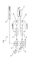
図1は本発明の一実施形態に係る受信装置100の要部の構成を示すブロック図である。
Hereinafter, a reception control device and a switching control method (hereinafter simply referred to as “reception device”) of the present invention will be described with reference to the drawings. The receiving device can be applied to, for example, a vehicle-mounted device such as a vehicle-mounted television receiver, and can be applied to a receiving device mounted on a mobile phone or a PDA (Personal Digital Assistance) terminal in the future. It is.
(1) Description of Embodiment FIG. 1 is a block diagram showing a configuration of a main part of a receiving
この図1に示すように、本実施形態の受信装置100は、例えば、複数のアンテナ1と、アンテナセレクタ2と、スイッチドビーム制御部3と、アンテナ切替監視部4と、PWM(Pulse Width Modulation)オフセット制御部5と、チューナー6と、AGC(Automatic Gain Control)7と、復調回路8とをそなえて構成される。
ここで、複数のアンテナ1は、放送局からの放送電波を受信するために用いられるもので、アンテナセレクタ(切替選択部)2は、前記複数のアンテナ1の中から使用するアンテナを切替選択するスイッチ動作を行なうためのものであり、例えばハードウェアスイッチなどにより実現される。
As shown in FIG. 1, the receiving
Here, the plurality of
スイッチドビーム制御部(アンテナ切替制御部)3は、前記アンテナセレクタ2による前記複数のアンテナ1の切替選択を制御して、アンテナの指向性を制御するスイッチドビーム制御(アンテナ切替制御)を行なうためのものであり、さらに、アンテナ切替選択を行なうまでの時間情報に関するアンテナ切替開始通知信号(アンテナ切替開始タイマー信号)を前記のアンテナ切替選択制御に先行してアンテナ切替監視部4に出力するものである。また、スイッチドビーム制御の際のアンテナ1の増減に関する情報(スイッチドビームアンテナ切替波形情報)をアンテナ切替監視部4に出力することができるようにもなっている。
A switched beam control unit (antenna switching control unit) 3 performs switched beam control (antenna switching control) for controlling the directivity of the antennas by controlling switching selection of the plurality of
アンテナ切替監視部4は、前記アンテナ切替開始通知信号に基づいて、PWMオフセット制御部(オフセット制御部)5でのオフセット付きPWM信号(オフセット付き利得制御信号)生成の契機となるアンテナ切替予告信号を前記のアンテナ切替選択制御に先行してPWMオフセット制御部5に出力するものである。なお、スイッチドビーム制御部3が、アンテナ切替開始通知信号をPWMオフセット制御部5に直接出力するように構成されてもよく、この場合には、受信装置は、図1の構成からアンテナ切替監視部4を削除した構成となる。さらに、アンテナ切替開始通知信号が、スイッチドビームアンテナ切替波形情報を含むようにしてもよい。
Based on the antenna switching start notification signal, the antenna switching monitoring unit 4 generates an antenna switching notification signal that triggers generation of a PWM signal with offset (gain control signal with offset) in the PWM offset control unit (offset control unit) 5. Prior to the antenna switching selection control, it is output to the PWM offset control unit 5. Note that the switched
PWMオフセット制御部(オフセット制御部)5は、前記アンテナ切替開始通知信号に基づいて、AGC7からのPWM信号(利得制御信号)にオフセット値を付したオフセット付きPWM信号(オフセット付き自動利得信号)をチューナー6に対して出力するものであり、このオフセット値を付すタイミングやそのオフセット量についての設定は、ユーザが外部から設定しうるようになっている。これらの設定方法及びその効果については、図2及び図4を用いて後述する。 The PWM offset control unit (offset control unit) 5 generates a PWM signal with an offset (automatic gain signal with offset) obtained by adding an offset value to the PWM signal (gain control signal) from the AGC 7 based on the antenna switching start notification signal. This is output to the tuner 6, and the timing for adding the offset value and the setting for the offset amount can be set by the user from the outside. These setting methods and their effects will be described later with reference to FIGS.
チューナー6は、放送電波を受信して選局するためのもので、複数(本実施形態では2機)そなえられ、それぞれ内部に受信した信号を増幅するための増幅器(図示省略)を備えて構成される。
AGC(自動利得制御部)7は、前記チューナー6で増幅された放送信号出力レベル(IF信号出力レベル)に基づいてチューナー6の利得制御を行なうためのPWM信号(利得制御信号)を生成、出力するためのもので、前記複数のチューナー6に対してそれぞれそなえられている。なお、AGC7がチューナー6での利得制御を行なうために生成、出力するものは、PWM信号に限らず、利得制御を行なえるような信号(利得制御信号)であればよい。
The tuner 6 is for receiving a broadcast radio wave and selecting a channel, and is provided with a plurality (two in this embodiment), each having an amplifier (not shown) for amplifying the received signal. Is done.
An AGC (automatic gain control unit) 7 generates and outputs a PWM signal (gain control signal) for performing gain control of the tuner 6 based on the broadcast signal output level (IF signal output level) amplified by the tuner 6. The plurality of tuners 6 are provided respectively. Note that what is generated and output for the AGC 7 to perform gain control in the tuner 6 is not limited to the PWM signal, but may be any signal (gain control signal) capable of gain control.
復調回路8は、前記チューナー6からの出力信号を復調してトランスポートストリーム(TS:Transport Stream)として出力するためのものであり、前記複数のチューナー6により共用されている。
このような構成により、スイッチドビーム制御部3によるアンテナ切替制御に先行して、チューナー6における受信信号の利得制御を行なうことができ、利得制御に要する時間を従来よりも短縮することが可能となる。このため、上記アンテナ切替制御が頻繁に行なわれた場合においても、前記利得制御を正常に行なうことができるので、上記受信装置において、正確かつ安定した受信制御を行なうことが可能となる。
The
With such a configuration, the gain control of the received signal in the tuner 6 can be performed prior to the antenna switching control by the switched
以下、図2を用いて、上述のごとく構成された本実施形態の受信装置の動作について詳述する。
図2はPWMオフセット制御部5の構成の一例を示すブロック図である。
この図2に示すように、前記PWMオフセット制御部5は、例えば、オフセットタイミング制御部9と、設定値レジスタ10と、オフセット値加減算制御部11とをそなえて構成される。
Hereinafter, the operation of the receiving apparatus according to the present embodiment configured as described above will be described in detail with reference to FIG.
FIG. 2 is a block diagram showing an example of the configuration of the PWM offset control unit 5.
As shown in FIG. 2, the PWM offset control unit 5 includes, for example, an offset timing control unit 9, a
ここで、オフセットタイミング制御部9は、前記アンテナ切替開始通知信号を契機として、設定値レジスタ10に保持されているオフセットタイミング(例えば、オフセットタイミング1,2,3)の値に基づき、オフセット値を加減算するタイミングを生成し、これをオフセットタイミング信号として出力するものである。これにより、オフセット値を時間に応じて段階的に変化させてPWM信号に付加することが可能となるので、きめ細かい利得制御が可能となり、IF信号の入力レベル変動を更に抑制することができる。
Here, the offset timing control unit 9 uses the antenna switching start notification signal as an opportunity to set the offset value based on the value of the offset timing (for example, offset
設定値レジスタ10は、オフセットタイミング制御部9及びオフセット値加減算制御部11と協働することにより、オフセット値を変更可能なオフセット値制御部として動作するもので、オフセット値に関する各種設定を保持するためのものである。本例では、前記オフセットタイミングや、オフセット値をそれぞれ保持している。なお、これらの設定値は、外部からのレジスタアクセスにより変更可能とすることで、例えば、オフセット値の増分及び減分を個別に設定したりすることもできるようになっているので、よりきめ細かい利得制御が可能となり、IF信号の入力レベル変動の更なる抑制を図ることができる。。また、本例では、オフセットタイミングとしてオフセットタイミング1,2,3を、オフセット値としてオフセット値A,B,C,Dを保持するものとする。
The
オフセット値加減算制御部11は、AGC7からのPWM信号にオフセット値を加算あるいは減算するためのものであり、前記オフセットタイミング制御部9からのオフセットタイミング信号と、前記設定値レジスタ10からのオフセット値とに基づいて、AGC7からのPWM信号にオフセットを付するためのものである。なお、これらのオフセットタイミングやオフセット値に関する設定は、設定値レジスタ10に保持された複数の設定の中から選択的に変更することができるので、IF信号の変動レベルを抑制するのに最適なオフセット付きPWM信号を短時間で生成することが可能となる。また、オフセット付きPWM信号の生成を簡単な加減算回路を用いることで実現でき、省スペース化及び省コスト化を図ることもできる。さらに、このとき、アンテナ切替監視部4から、前記スイッチドビームアンテナ切替波形より識別されるアンテナの増減情報(スイッチドビームアンテナ切替波形情報)を受信するようにもでき、これにより、アンテナの使用数の増減に応じて上記オフセットタイミングや上記オフセット量の設定が最適なものになるように切り替えることもできるので、前記利得制御動作のさらなる高速化を図ることが可能となる。
The offset value addition /
そして、前記オフセット値加減算制御部11によりオフセット付きPWM制御信号がチューナー6へと出力され、このオフセット付きPWM制御信号に基づいてチューナー6での利得制御が行なわれるようになっている。
また、上述したPWMオフセット制御部5は、複数のチューナー6に対してそれぞれ同様にそなえられており、オフセットに関する設定(ここでは、オフセットタイミングやオフセット値をいう)を複数のチューナー6に対して個別に設定可能となっている。これにより、多様なアンテナ切替選択が行なわれる場合でも、それぞれ個別にオフセットを設定して利得制御を行なうことが可能となるので、より効果的な利得制御を行なうことができ、IF信号のレベル変動をさらに抑制することが可能となる。
The offset value addition /
The PWM offset control unit 5 described above is similarly provided for each of the plurality of tuners 6, and settings relating to offset (here, offset timing and offset value) are individually set for the plurality of tuners 6. Can be set. As a result, even when various antenna switching selections are made, it is possible to individually set an offset and perform gain control, so that more effective gain control can be performed, and IF signal level fluctuations Can be further suppressed.
なお、上記の設定値レジスタ10は、専用のメモリやHDD等の記憶装置によって実現してもよいし、その他の機能の一部又は全部を兼用する記憶装置によって実現してもよい。これにより、前記記憶装置に、タイミングに関する設定値を記憶することができるので、タイミング処理に必要な回路規模を縮小させることが可能となる。また、上記のスイッチドビーム制御部3,アンテナ切替監視部4と,PWMオフセット制御部5,チューナー6,AGC7,復調回路8としての機能は、例えば本受信装置100に搭載のCPUやMPU等のプロセッサ(図示省略)が所定のアプリケーションプログラムを読み取って動作することにより実現される。そのプログラムは、例えば、フレキシブルディスクやCD−ROM,DVD−ROM/RAM,磁気ディスク,光磁気ディスク等の記録媒体に格納された形態で上記記憶装置に提供(インストール)されてもよいし、無線ネットワーク(通信回線)を介してダウンロードする形態で提供されてもよい。
The
(1.1)動作説明
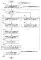
以下、上述のごとく構成された本実施形態の受信制御装置における切替制御方法について、図3に示すフローチャートを参照しながら説明する。
この図3に示すように、本切替制御方法では、まず、アンテナセレクタ2によるアンテナ切替選択動作に先行して、スイッチドビーム制御部3がアンテナ切替監視部4にアンテナ切替通知信号を出力し、さらに、アンテナ切替監視部4が、アンテナ切替予告信号をPWMオフセット制御部5に出力する(ステップS10、アンテナ切替開始通知ステップ)。
(1.1) Description of Operation Hereinafter, the switching control method in the reception control apparatus of the present embodiment configured as described above will be described with reference to the flowchart shown in FIG.
As shown in FIG. 3, in this switching control method, first, prior to the antenna switching selection operation by the
そして、PWMオフセット制御部5は、アンテナ切替予告信号に含まれるスイッチドビーム制御部3からのスイッチドビームアンテナ切替波形情報に基づいて、アンテナ数が増加したかどうかを判定し(ステップS1)、アンテナ数が増加したと判定した場合には(ステップS1のyesルート)、アンテナ数が増加した場合のためのオフセットタイミング及びオフセット値をそれぞれ設定値レジスタ10に設定する(ステップS2,ステップS3)。一方、アンテナ数が増加したと判定されなかった場合は(ステップS1のnoルート)、アンテナ数が減少した場合のためのオフセットタイミング及びオフセット値をそれぞれ設定値レジスタ10に設定する(ステップS4,ステップS5)。なお、ここでいうアンテナ数が増加あるいは減少した場合のためのオフセットタイミング及びオフセット値とは、アンテナ数が増加あるいは減少した場合にチューナー6での利得が最適となる、即ち、IF信号のレベル変動が効果的に抑制されるような利得制御を可能とする、オフセット付きPWM信号を生成できるオフセット設定のことをいう。また、アンテナ数が増加した場合と減少した場合とで、同じオフセット設定を用いるようにしてもよく、この場合には、ステップS1,S4,S5の処理は不要となり、さらに、スイッチドビームアンテナ切替波形情報も不要となるため処理を高速化することができる。
Then, the PWM offset control unit 5 determines whether the number of antennas has increased based on the switched beam antenna switching waveform information from the switched
次に、オフセットタイミング制御部9が、設定値レジスタ10に保持されたオフセットタイミングを読み込み(ステップS6)、オフセットタイミング信号を生成、出力する。
そして、オフセット値加減算制御部11が、前記オフセットタイミング信号を読み込むとともに、設定値レジスタ10に保持されたオフセット値を読み込み(ステップS7)、さらに、AGC7からのPWM信号を読み込んで(ステップS8)、ステップS9において、オフセット付きPWM信号を生成する(ステップS20、オフセット付き利得制御信号作成ステップ)。つまり、アンテナ切替開始通知信号がON状態である場合にオフセット付きPWM信号は生成されるようになっている。
Next, the offset timing control unit 9 reads the offset timing held in the set value register 10 (step S6), and generates and outputs an offset timing signal.
Then, the offset value addition /
ついで、ステップS9において生成されたオフセット付き利得制御信号をチューナー6に入力する(ステップS30、オフセット付き利得制御信号入力ステップ)ことにより、本切替制御方法を実現する。
ここで、以上の処理により得られる効果について、図4(a)、図4(b)を用いて具体的に説明する。
Next, the switching control method is realized by inputting the gain control signal with offset generated in step S9 to the tuner 6 (step S30, gain control signal input step with offset).
Here, the effect obtained by the above processing will be specifically described with reference to FIGS. 4 (a) and 4 (b).
図4(a)はスイッチドビーム制御によりアンテナ1の使用数が減少する前後でのスイッチドビームアンテナ切替波形,アンテナ切替予告信号(アンテナ切替開始通知信号),オフセット,オフセット付き利得制御量およびIF入力信号レベルについてのタイミング図であり、図4(b)はオフセット値及びオフセットタイミング設定を詳述するためのタイミング図である。なお、図中の点線(i)は、アンテナ切替開始通知信号が生成されるとともにPWMオフセット制御部5に入力されるタイミングを表し、また、点線(ii)は、スイッチドビームアンテナ切替波形がONからOFF、即ち、アンテナ切替選択が行なわれてアンテナ数が減少するタイミングを表しており、さらに、点線(iii)は、アンテナ切替開始通知信号がOFFとなるタイミングを表している。
FIG. 4A shows a switched beam antenna switching waveform, an antenna switching notice signal (antenna switching start notification signal), an offset, a gain control amount with an offset, and an IF before and after the number of
まず、(i)〜(ii)の区間では、(i)に示すタイミングで、アンテナ切替監視部4により、アンテナ切替開始通知信号がON状態になる。ここで、スイッチドビーム制御部3によりアンテナ切替制御が行なわれるのは、(ii)で示すタイミングであるので、アンテナ切替選択に先行してアンテナ切替開始通知信号がON状態となっていることになる。なお、アンテナ切替開始通知信号をアンテナ切替選択に対してどのくらい先行させるかは、例えばスイッチドビーム制御部3に設定される所定値を変更することにより、ユーザが適宜変更できるようになっている。
First, in the sections (i) to (ii), the antenna switching start notification signal is turned on by the antenna switching monitoring unit 4 at the timing shown in (i). Here, since the antenna switching control is performed by the switched
そして、例えば、図4に示すアンテナ切替開始通知信号がONとなるタイミング(i)よりも早いタイミングでアンテナ切替開始通知信号をONにした場合は、IF入力信号レベルの変化をさらに緩やかにすることもできる。しかしながら、上記タイミング(i)を過剰に早く設定すると、頻繁にアンテナ切替選択が行なわれた場合に、利得制御処理がアンテナ切替選択処理に間に合わなくなる可能性が生じるので、上記タイミング(i)については、アンテナ切替選択処理の発生頻度等の状況に応じて最も適当なタイミングとなるように設定するのが好ましい。 For example, when the antenna switching start notification signal is turned on at an earlier timing than the timing (i) when the antenna switching start notification signal shown in FIG. 4 is turned on, the change in the IF input signal level is further moderated. You can also. However, if the timing (i) is set too early, the gain control process may not be in time for the antenna switching selection process when the antenna switching selection is frequently performed. It is preferable that the most appropriate timing is set according to the situation such as the occurrence frequency of the antenna switching selection process.
また、アンテナ切替開始通知信号がONとなるのを契機として、PWMオフセット制御部5が、上述したステップによりオフセットを生成して、オフセット付きPWM信号がチューナー6に出力される。これにより、オフセット付き利得制御量が増加するとともに、IF入力信号レベルもゆるやかに上昇している。
一方、(ii)〜(iii)の区間では、まず、(ii)に示すタイミングで、アンテナセレクタ2により、アンテナ1の切替選択処理が行なわれる。これにより、IF入力信号レベルが下降し始めるが、アンテナ切替選択処理に先行して、オフセット付きPWM信号に基づいて利得制御が行なわれていたので、従来と比較して、ゆるやかな下降にとどまっている。
In response to the antenna switching start notification signal being turned on, the PWM offset control unit 5 generates an offset by the above-described steps, and the offset-added PWM signal is output to the tuner 6. As a result, the amount of gain control with offset increases, and the IF input signal level gradually increases.
On the other hand, in the sections (ii) to (iii), first, the
また、この区間では、オフセットも減少し始めるので、オフセット付き利得制御量も収束し始めている。
そして、(iii)で示すタイミングで、アンテナ切替開始通知信号がOFFとなり、オフセットもゼロとなる。また、このとき既に、オフセット付き利得制御量及びIF入力信号レベルも収束している。
In this section, since the offset also starts to decrease, the gain control amount with offset starts to converge.
Then, at the timing shown in (iii), the antenna switching start notification signal is turned OFF and the offset is also zero. At this time, the gain control amount with offset and the IF input signal level have already converged.
ここで、図4(b)を用いて、オフセット値及びオフセットタイミング設定について説明する。
点線(i),(iii),(iv),(v)は、それぞれオフセット値が変化するタイミン
グを表しており、オフセット値A〜D及びオフセットタイミング(1)〜(3)は、それぞれ設定値レジスタ10に予め保持された設定値である。
Here, offset value and offset timing setting will be described with reference to FIG.
Dotted lines (i), (iii), (iv), and (v) represent timings at which the offset values change, and offset values A to D and offset timings (1) to (3) are set values, respectively. The set value is stored in the
本例では、オフセット値を、A=B=−C=−D>0とし、かつ、オフセットタイミングを、(1)=(2)=(3)と設定することにより、オフセット付き利得制御量が急激に変化しない、即ち、IF入力信号レベルが急激にかつ大きく変動しないように利得を制御しているが、これらの設定値は自在に変更することも可能である。例えば、アンテナ数が増加した場合には、オフセット値を、−A=−B=C=D>0とすることにより、IF入力信号レベルを効果的に制御することが可能となり、また、オフセットタイミングの設定値の数を多くするとともにオフセット値を小さく変化させることにより、利得制御量をより細かく制御することが可能となり、IF入力信号のレベル変動を更に抑制することが可能となる。なお、オフセット値はリニア(連続的)に変化させてもよい。 In this example, by setting the offset value as A = B = −C = −D> 0 and setting the offset timing as (1) = (2) = (3), the gain control amount with offset is The gain is controlled so that it does not change abruptly, that is, the IF input signal level does not fluctuate rapidly and greatly, but these set values can be freely changed. For example, when the number of antennas increases, it is possible to effectively control the IF input signal level by setting the offset value to −A = −B = C = D> 0, and the offset timing. By increasing the number of set values and changing the offset value to a small value, the gain control amount can be controlled more finely, and the level fluctuation of the IF input signal can be further suppressed. The offset value may be changed linearly (continuously).
以上の処理により、チューナー6からのIF入力信号信号をより短時間で一定レベルに維持することができるので、受信状態が安定し、これにより、ユーザの不快感を低減させることが可能となる。
(2)その他
以上、本発明の一実施形態について詳細に説明したが、本発明は上記の実施形態に限定されるものではなく、本発明の趣旨を逸脱しない範囲において任意に変形して実施することができる。
With the above processing, the IF input signal signal from the tuner 6 can be maintained at a constant level in a shorter time, so that the reception state is stabilized, thereby making it possible to reduce user discomfort.
(2) Others Although one embodiment of the present invention has been described in detail above, the present invention is not limited to the above-described embodiment, and may be arbitrarily modified and implemented without departing from the spirit of the present invention. be able to.
例えば、上記の受信装置は、必ずしも上述した各種機能をすべて具備している必要はない。例えば、受信制御装置として動作する場合には、アンテナ1は装備しなくてもよいし、チューナー6が1機しかない場合には、PWMオフセット制御部5、AGC7は、それぞれ1機でよい。また、設定値レジスタ10を大容量のレジスタで構成すれば、オフセットに関する設定値(オフセット値、オフセットタイミングなど)をより多く取ることもできる。また、アンテナ1は、3機以下あるいは5機以上であってもよく、オフセット制御部5、チューナー6、自動利得制御部7をそれぞれ3機以上そなえてもよい。
For example, the above receiving apparatus does not necessarily have all the various functions described above. For example, when operating as a reception control apparatus, the
(3)付記
(付記1)
複数のアンテナを切替選択する切替選択部と、
該切替選択部による前記複数のアンテナの切替選択を制御するとともに当該アンテナの切替選択を行なうに先立って、アンテナ切替開始通知信号を出力するアンテナ切替制御部と、
該切替選択部により切替選択されたアンテナで受信した信号から選局し増幅するチューナーと、
該チューナーによって増幅された放送信号に基づいて、該チューナーでの利得制御量を制御する利得制御信号を出力する自動利得制御部と、
該アンテナ切替開始通知信号に従って、該自動利得制御部からの該自動利得信号にオフセット値を付してオフセット付き利得制御信号を生成するオフセット制御部とをそなえたことを特徴とする、受信制御装置。
(3) Appendix (Appendix 1)
A switching selection unit for switching and selecting a plurality of antennas;
An antenna switching control unit that controls switching selection of the plurality of antennas by the switching selection unit and outputs an antenna switching start notification signal prior to performing switching selection of the antenna;
A tuner for selecting and amplifying from a signal received by an antenna switched and selected by the switching selection unit;
An automatic gain control unit that outputs a gain control signal for controlling a gain control amount in the tuner based on the broadcast signal amplified by the tuner;
A reception control device comprising: an offset control unit that generates an offset gain control signal by adding an offset value to the automatic gain signal from the automatic gain control unit according to the antenna switching start notification signal .
(付記2)
該オフセット制御部が、
該オフセット値を変更可能なオフセット値制御部をそなえ、当該オフセット値制御部が該オフセット値を変更することにより該利得制御量を制御することを特徴とする、付記1に記載の受信制御装置。
(Appendix 2)
The offset control unit
The reception control apparatus according to
(付記3)
該オフセット値制御部が、
該オフセット値を段階的に変化させることを特徴とする、付記2に記載の受信制御装置。
(付記4)
該オフセット値制御部が、
該オフセット値の増分と減分とを個別に設定することを特徴とする、付記2または付記3に記載の受信制御装置。
(Appendix 3)
The offset value control unit
The reception control apparatus according to
(Appendix 4)
The offset value control unit
4. The reception control device according to
(付記5)
前記複数のチューナーに対してそれぞれそなえられたオフセット制御部が、
該オフセット値に関する設定をそれぞれ個別に有することを特徴とする、付記1〜4のいずれか1項に記載の受信制御装置。
(付記6)
該オフセット制御部が、
該オフセット値を変更するタイミングを変更可能なオフセットタイミング制御部をそなえることを特徴とする、付記1〜5のいずれか1項に記載の受信制御装置。
(Appendix 5)
An offset control unit provided for each of the plurality of tuners,
5. The reception control apparatus according to any one of
(Appendix 6)
The offset control unit
The reception control apparatus according to any one of
(付記7)
該オフセットタイミング制御部が、
該オフセット値を変更するタイミングを決定するためのオフセットタイミング値を複数個そなえ、該オフセットタイミング値を選択的に変更することを特徴とする、付記6記載の受信制御装置。
(Appendix 7)
The offset timing control unit
The reception control apparatus according to appendix 6, wherein a plurality of offset timing values for determining the timing for changing the offset value are provided, and the offset timing value is selectively changed.
(付記8)
前記複数のチューナーに対してそれぞれそなえられたオフセット制御部が、
該オフセットタイミング値に関する設定をそれぞれ個別に有することを特徴とする、付記6または付記7に記載の受信制御装置。
(付記9)
該オフセット制御部が、
該オフセット値及び該オフセットタイミング値に関する設定を、アンテナの増減に対応してそれぞれそなえることを特徴とする、付記6〜8のいずれか1項に記載の受信制御装置。
(Appendix 8)
An offset control unit provided for each of the plurality of tuners,
8. The reception control device according to appendix 6 or appendix 7, wherein each setting relating to the offset timing value is individually provided.
(Appendix 9)
The offset control unit
9. The reception control device according to any one of appendices 6 to 8, wherein the setting relating to the offset value and the offset timing value is provided corresponding to the increase or decrease of the antenna.
(付記10)
複数のアンテナと、前記複数のアンテナを切替選択する切替選択部と、該切替選択部により切替選択されたアンテナで受信した信号を選局し増幅するチューナーと、当該チューナーによって増幅された該信号に基づいて、該チューナーでの利得制御量を制御する自動利得信号を出力する自動利得制御部とをそなえた受信装置における切替制御方法であって、
該切替選択部により前記アンテナの切替選択を行なうに先立ってアンテナ切替開始通知信号を出力するアンテナ切替開始通知ステップと、
該アンテナ切替開始通知信号が出力されると、該自動利得制御部からの該自動利得信号にオフセット値を付してオフセット付き利得制御信号を生成するオフセット付き利得制御信号作成ステップと、
該オフセット付き利得制御信号作成ステップにおいて作成された該オフセット付き利得制御信号を、該チューナに入力するオフセット付き利得制御信号入力ステップとをそなえたことを特徴とする、切替制御方法。
(Appendix 10)
A plurality of antennas, a switching selection unit that switches and selects the plurality of antennas, a tuner that selects and amplifies a signal received by the antenna that is switched and selected by the switching selection unit, and the signal amplified by the tuner Based on the above, a switching control method in a receiving device including an automatic gain control unit that outputs an automatic gain signal for controlling a gain control amount in the tuner,
An antenna switching start notification step for outputting an antenna switching start notification signal prior to performing the antenna switching selection by the switching selection unit;
When the antenna switching start notification signal is output, an offset gain control signal creation step for generating an offset gain control signal by adding an offset value to the automatic gain signal from the automatic gain control unit;
A switching control method comprising: an offset-added gain control signal input step for inputting the offset-added gain control signal generated in the offset-added gain control signal generating step to the tuner.
(付記11)
該オフセット付き利得制御信号作成ステップにおいて、
該オフセット値を変更することにより該利得制御量を制御することを特徴とする、付記10に記載の切替制御方法。
(付記12)
該オフセット付き利得制御信号作成ステップにおいて、
該オフセット値を段階的に変化させることを特徴とする、付記11に記載の切替制御方法。
(Appendix 11)
In the gain control signal creation step with offset,
The switching control method according to
(Appendix 12)
In the gain control signal creation step with offset,
The switching control method according to
(付記13)
該オフセット付き利得制御信号作成ステップにおいて、
該オフセット値の増分と減分とを個別に設定しうることを特徴とする、付記11または付記12に記載の切替制御方法。
(付記14)
該オフセット付き利得制御信号作成ステップにおいて、
該オフセット値に関する設定を、前記複数のチューナーに対してそれぞれそなえられたPWMオフセット制御部に対してそれぞれ個別に作成しうることを特徴とする、付記10〜13のいずれか1項に記載の切替制御方法。
(Appendix 13)
In the gain control signal creation step with offset,
The switching control method according to
(Appendix 14)
In the gain control signal creation step with offset,
The switching according to any one of
(付記15)
該オフセット付き利得制御信号作成ステップにおいて、
該オフセット値を変更するタイミングを変更しうることを特徴とする、付記10〜14のいずれか1項に記載の切替制御方法。
(付記16)
該オフセット付き利得制御信号作成ステップにおいて、
該オフセット値を変更するタイミングを決定するためのオフセットタイミング値を複数個作成し、該オフセットタイミング値を選択的に変更しうることを特徴とする、付記15記載の切替制御方法。
(Appendix 15)
In the gain control signal creation step with offset,
15. The switching control method according to any one of
(Appendix 16)
In the gain control signal creation step with offset,
16. The switching control method according to
(付記17)
該オフセット付き利得制御信号作成ステップにおいて、
該オフセットタイミング値に関する設定を、前記複数のチューナーに対してそれぞれ個別に作成しうることを特徴とする、付記15または付記16に記載の切替制御方法。
(付記18)
該オフセット付き利得制御信号作成ステップにおいて、
該オフセット値及び該オフセットタイミング値に関する設定を、アンテナの増減に対応してそれぞれ作成しうることを特徴とする、付記15〜17のいずれか1項に記載の切替制御方法。
(Appendix 17)
In the gain control signal creation step with offset,
The switching control method according to
(Appendix 18)
In the gain control signal creation step with offset,
18. The switching control method according to any one of
(付記19)
放送電波を受信する複数のアンテナと、
前記複数のアンテナを切替選択する切替選択部と、
該切替選択部による前記複数のアンテナの切替選択を制御するとともに当該アンテナの切替選択を行なうに先立って、アンテナ切替開始通知信号を出力するアンテナ切替制御部と、
該切替選択部により切替選択されたアンテナで受信した信号から選局し増幅するチューナーと、
該チューナーによって増幅された放送信号に基づいて、該チューナーでの利得制御量を制御する自動利得信号を出力する自動利得制御部と、
該アンテナ切替監視部からの該アンテナ切替開始通知信号に従って、該自動利得制御部からの該自動利得信号にオフセット値を付してオフセット付き利得制御信号を生成するオフセット制御部とをそなえたことを特徴とする、受信装置。
(Appendix 19)
Multiple antennas to receive broadcast waves,
A switching selection unit for switching and selecting the plurality of antennas;
An antenna switching control unit that controls switching selection of the plurality of antennas by the switching selection unit and outputs an antenna switching start notification signal prior to performing switching selection of the antenna;
A tuner for selecting and amplifying from a signal received by an antenna switched and selected by the switching selection unit;
An automatic gain control unit for outputting an automatic gain signal for controlling a gain control amount in the tuner based on the broadcast signal amplified by the tuner;
An offset control unit for generating an offset gain control signal by adding an offset value to the automatic gain signal from the automatic gain control unit in accordance with the antenna switching start notification signal from the antenna switching monitoring unit. A receiving device.
1 アンテナ
2 アンテナセレクタ(切替選択部)
3 スイッチドビーム制御部(アンテナ切替制御部)
4 アンテナ切替監視部
5 PWMオフセット制御部(オフセット制御部)
6 チューナー
7 AGC(自動利得制御部)
8 復調回路
9 オフセットタイミング制御部
10 設定値レジスタ
11 オフセット値加減算制御部
100 受信装置
1
3 Switched beam control unit (antenna switching control unit)
4 Antenna switching monitoring unit 5 PWM offset control unit (offset control unit)
6 Tuner 7 AGC (Automatic Gain Control Unit)
8 Demodulation circuit 9 Offset
Claims (4)
該切替選択部による前記複数のアンテナの切替選択を制御するとともに当該アンテナの切替選択を行なうに先立って、アンテナ切替開始通知信号を出力するアンテナ切替制御部と、
該切替選択部により切替選択されたアンテナで受信した信号から選局し増幅するチューナーと、
該チューナーによって増幅された放送信号に基づいて、該チューナーでの利得制御量を制御する利得制御信号を出力する自動利得制御部と、
該アンテナ切替開始通知信号に従って、該自動利得制御部からの該自動利得信号にオフセット値を付してオフセット付き利得制御信号を生成するオフセット制御部とをそなえたことを特徴とする、受信制御装置。 A switching selection unit for switching and selecting a plurality of antennas;
An antenna switching control unit that controls switching selection of the plurality of antennas by the switching selection unit and outputs an antenna switching start notification signal prior to performing switching selection of the antenna;
A tuner for selecting and amplifying from a signal received by an antenna switched and selected by the switching selection unit;
An automatic gain control unit that outputs a gain control signal for controlling a gain control amount in the tuner based on the broadcast signal amplified by the tuner;
A reception control device comprising: an offset control unit that generates an offset gain control signal by adding an offset value to the automatic gain signal from the automatic gain control unit according to the antenna switching start notification signal .
該オフセット値を変更可能なオフセット値制御部をそなえ、当該オフセット値制御部が該オフセット値を変更することにより該利得制御量を制御することを特徴とする、請求項1に記載の受信制御装置。 The offset control unit
The reception control device according to claim 1, further comprising an offset value control unit capable of changing the offset value, wherein the offset value control unit controls the gain control amount by changing the offset value. .
該オフセット値を変更するタイミングを変更可能なオフセットタイミング制御部をそなえることを特徴とする、請求項1または請求項2に記載の受信制御装置。 The offset control unit
The reception control apparatus according to claim 1, further comprising an offset timing control unit capable of changing a timing of changing the offset value.
該切替選択部により前記アンテナの切替選択を行なうに先立ってアンテナ切替開始通知信号を出力するアンテナ切替開始通知ステップと、
該アンテナ切替開始通知信号が出力されると、該自動利得制御部からの該自動利得信号にオフセット値を付してオフセット付き利得制御信号を生成するオフセット付き利得制御信号作成ステップと、
該オフセット付き自動利得信号作成ステップにおいて作成された該オフセット付き利得制御信号を、該チューナに入力するオフセット付き利得制御信号入力ステップとをそなえたことを特徴とする、切替制御方法。
A plurality of antennas, a switching selection unit that switches and selects the plurality of antennas, a tuner that selects and amplifies a signal received by the antenna that is switched and selected by the switching selection unit, and the signal amplified by the tuner Based on the above, a switching control method in a receiving device including an automatic gain control unit that outputs an automatic gain signal for controlling a gain control amount in the tuner,
An antenna switching start notification step for outputting an antenna switching start notification signal prior to performing the antenna switching selection by the switching selection unit;
When the antenna switching start notification signal is output, an offset gain control signal creation step for generating an offset gain control signal by adding an offset value to the automatic gain signal from the automatic gain control unit;
A switching control method comprising: an offset-added gain control signal input step for inputting the offset-added gain control signal generated in the offset-added automatic gain signal generating step to the tuner.
Priority Applications (1)
| Application Number | Priority Date | Filing Date | Title |
|---|---|---|---|
| JP2006120556A JP2007295253A (en) | 2006-04-25 | 2006-04-25 | Reception control device and switching control method |
Applications Claiming Priority (1)
| Application Number | Priority Date | Filing Date | Title |
|---|---|---|---|
| JP2006120556A JP2007295253A (en) | 2006-04-25 | 2006-04-25 | Reception control device and switching control method |
Publications (1)
| Publication Number | Publication Date |
|---|---|
| JP2007295253A true JP2007295253A (en) | 2007-11-08 |
Family
ID=38765428
Family Applications (1)
| Application Number | Title | Priority Date | Filing Date |
|---|---|---|---|
| JP2006120556A Withdrawn JP2007295253A (en) | 2006-04-25 | 2006-04-25 | Reception control device and switching control method |
Country Status (1)
| Country | Link |
|---|---|
| JP (1) | JP2007295253A (en) |
Cited By (2)
| Publication number | Priority date | Publication date | Assignee | Title |
|---|---|---|---|---|
| JP2012065286A (en) * | 2010-09-17 | 2012-03-29 | Panasonic Electric Works Co Ltd | Antenna switching reception system |
| CN110268639A (en) * | 2017-01-27 | 2019-09-20 | 日本电信电话株式会社 | Wireless base station and its control method |
-
2006
- 2006-04-25 JP JP2006120556A patent/JP2007295253A/en not_active Withdrawn
Cited By (3)
| Publication number | Priority date | Publication date | Assignee | Title |
|---|---|---|---|---|
| JP2012065286A (en) * | 2010-09-17 | 2012-03-29 | Panasonic Electric Works Co Ltd | Antenna switching reception system |
| CN110268639A (en) * | 2017-01-27 | 2019-09-20 | 日本电信电话株式会社 | Wireless base station and its control method |
| CN110268639B (en) * | 2017-01-27 | 2022-04-01 | 日本电信电话株式会社 | Radio base station and control method thereof |
Similar Documents
| Publication | Publication Date | Title |
|---|---|---|
| EP1542420B1 (en) | Method and device with adaptive antenna array reception | |
| JP4574681B2 (en) | Diversity receiver | |
| JP4843094B2 (en) | Receiving device and program | |
| KR101020393B1 (en) | Ofdm receiving apparatus | |
| JP2008193476A (en) | Receiver, and reception system using the same | |
| JP4712866B2 (en) | Diversity receiving apparatus and diversity receiving method | |
| JP2007295253A (en) | Reception control device and switching control method | |
| JP2002290177A (en) | Receiver and automatic gain control method | |
| JP2005130076A (en) | Digital broadcast receiver | |
| JP2006352674A (en) | Receiver | |
| JP2008301135A (en) | Transmission device and method of optimizing power efficiency therefor | |
| KR20060093032A (en) | Device for receiving digital signals with fading compensation | |
| JP2010045706A (en) | Diversity reception device and electronic apparatus using the same | |
| JP2010283717A (en) | Receiver | |
| JP4538282B2 (en) | Automatic gain control device and automatic gain control method | |
| JP4157530B2 (en) | Diversity receiver | |
| JP4557835B2 (en) | Diversity receiver | |
| JP4378263B2 (en) | Receiver | |
| JP2006148735A (en) | Receiver | |
| JP4593344B2 (en) | Receiving method and receiving apparatus in frequency hopping communication | |
| JP2007235801A (en) | Fading estimate apparatus for receiving a plurality of channels, high frequency receiver using the same, and fading estimate method used therefor | |
| JP3767690B2 (en) | Diversity receiver | |
| JP2007228348A (en) | Diversity receiver | |
| JP2005191801A (en) | Receiver, receiving method, program for reception control, and recording medium | |
| JP2006229312A (en) | Sampling period adjuster |
Legal Events
| Date | Code | Title | Description |
|---|---|---|---|
| A300 | Withdrawal of application because of no request for examination |
Free format text: JAPANESE INTERMEDIATE CODE: A300 Effective date: 20090707 |