JP6741370B2 - 集積回路における信号の電力増幅のためのシステム、方法、及びデバイス - Google Patents
集積回路における信号の電力増幅のためのシステム、方法、及びデバイス Download PDFInfo
- Publication number
- JP6741370B2 JP6741370B2 JP2016548635A JP2016548635A JP6741370B2 JP 6741370 B2 JP6741370 B2 JP 6741370B2 JP 2016548635 A JP2016548635 A JP 2016548635A JP 2016548635 A JP2016548635 A JP 2016548635A JP 6741370 B2 JP6741370 B2 JP 6741370B2
- Authority
- JP
- Japan
- Prior art keywords
- power
- primary
- primary winding
- winding
- integrated circuit
- Prior art date
- Legal status (The legal status is an assumption and is not a legal conclusion. Google has not performed a legal analysis and makes no representation as to the accuracy of the status listed.)
- Active
Links
Images


Classifications
-
- H—ELECTRICITY
- H03—ELECTRONIC CIRCUITRY
- H03F—AMPLIFIERS
- H03F3/00—Amplifiers with only discharge tubes or only semiconductor devices as amplifying elements
- H03F3/20—Power amplifiers, e.g. Class B amplifiers, Class C amplifiers
- H03F3/21—Power amplifiers, e.g. Class B amplifiers, Class C amplifiers with semiconductor devices only
- H03F3/211—Power amplifiers, e.g. Class B amplifiers, Class C amplifiers with semiconductor devices only using a combination of several amplifiers
-
- H—ELECTRICITY
- H03—ELECTRONIC CIRCUITRY
- H03F—AMPLIFIERS
- H03F3/00—Amplifiers with only discharge tubes or only semiconductor devices as amplifying elements
- H03F3/189—High-frequency amplifiers, e.g. radio frequency amplifiers
- H03F3/19—High-frequency amplifiers, e.g. radio frequency amplifiers with semiconductor devices only
- H03F3/195—High-frequency amplifiers, e.g. radio frequency amplifiers with semiconductor devices only in integrated circuits
-
- H—ELECTRICITY
- H03—ELECTRONIC CIRCUITRY
- H03F—AMPLIFIERS
- H03F3/00—Amplifiers with only discharge tubes or only semiconductor devices as amplifying elements
- H03F3/20—Power amplifiers, e.g. Class B amplifiers, Class C amplifiers
- H03F3/24—Power amplifiers, e.g. Class B amplifiers, Class C amplifiers of transmitter output stages
- H03F3/245—Power amplifiers, e.g. Class B amplifiers, Class C amplifiers of transmitter output stages with semiconductor devices only
-
- H—ELECTRICITY
- H03—ELECTRONIC CIRCUITRY
- H03F—AMPLIFIERS
- H03F3/00—Amplifiers with only discharge tubes or only semiconductor devices as amplifying elements
- H03F3/72—Gated amplifiers, i.e. amplifiers which are rendered operative or inoperative by means of a control signal
-
- H—ELECTRICITY
- H03—ELECTRONIC CIRCUITRY
- H03F—AMPLIFIERS
- H03F2200/00—Indexing scheme relating to amplifiers
- H03F2200/537—A transformer being used as coupling element between two amplifying stages
-
- H—ELECTRICITY
- H03—ELECTRONIC CIRCUITRY
- H03F—AMPLIFIERS
- H03F2200/00—Indexing scheme relating to amplifiers
- H03F2200/541—Transformer coupled at the output of an amplifier
-
- H—ELECTRICITY
- H03—ELECTRONIC CIRCUITRY
- H03F—AMPLIFIERS
- H03F2203/00—Indexing scheme relating to amplifiers with only discharge tubes or only semiconductor devices as amplifying elements covered by H03F3/00
- H03F2203/20—Indexing scheme relating to power amplifiers, e.g. Class B amplifiers, Class C amplifiers
- H03F2203/21—Indexing scheme relating to power amplifiers, e.g. Class B amplifiers, Class C amplifiers with semiconductor devices only
- H03F2203/211—Indexing scheme relating to power amplifiers, e.g. Class B amplifiers, Class C amplifiers with semiconductor devices only using a combination of several amplifiers
- H03F2203/21145—Output signals are combined by switching a plurality of paralleled power amplifiers to a common output
-
- H—ELECTRICITY
- H03—ELECTRONIC CIRCUITRY
- H03F—AMPLIFIERS
- H03F2203/00—Indexing scheme relating to amplifiers with only discharge tubes or only semiconductor devices as amplifying elements covered by H03F3/00
- H03F2203/72—Indexing scheme relating to gated amplifiers, i.e. amplifiers which are rendered operative or inoperative by means of a control signal
- H03F2203/7221—Indexing scheme relating to gated amplifiers, i.e. amplifiers which are rendered operative or inoperative by means of a control signal the gated amplifier being switched on or off by a switch at the output of the amplifier
-
- H—ELECTRICITY
- H03—ELECTRONIC CIRCUITRY
- H03F—AMPLIFIERS
- H03F2203/00—Indexing scheme relating to amplifiers with only discharge tubes or only semiconductor devices as amplifying elements covered by H03F3/00
- H03F2203/72—Indexing scheme relating to gated amplifiers, i.e. amplifiers which are rendered operative or inoperative by means of a control signal
- H03F2203/7236—Indexing scheme relating to gated amplifiers, i.e. amplifiers which are rendered operative or inoperative by means of a control signal the gated amplifier being switched on or off by putting into parallel or not, by choosing between amplifiers by (a ) switch(es)
Landscapes
- Engineering & Computer Science (AREA)
- Power Engineering (AREA)
- Microelectronics & Electronic Packaging (AREA)
- Amplifiers (AREA)
- Transmitters (AREA)
Description
Claims (15)
- 集積回路であって、
第1の電力増幅器と、
第2の電力増幅器と、
前記第1の電力増幅器から単独に第1の電力を直接に受け取るように構成される第1の1次巻線と、
前記第2の電力増幅器から単独に第2の電力を直接に受け取るように構成される第2の1次巻線と、
2次巻線であって、前記第1の1次巻線と前記第2の1次巻線とから伝送される前記電力が前記2次巻線上で付加されるように、前記第1の1次巻線と前記第2の1次巻線との両方に共通に電磁気的に結合される、前記2次巻線と、
前記第1の1次巻線と前記第2の1次巻線とを含むループとしての電流経路であって、前記第1の電力増幅器と前記第2の電力増幅器との1つが「オフ」状態にあるときに前記第1の1次巻線と前記第2の1次巻線との少なくとも一方に誘導される第1の電流の流れを可能にする、前記電流経路と、
を含み
前記第1の電流が前記2次巻線を流れる電流により誘導され、前記電流経路が前記第1及び第2の電力増幅器の外にあり、
前記電流経路が第1のレジスタと第2のレジスタとを含み、前記第1のレジスタが前記第1及び第2の1次巻線の正端子の間に結合され、前記第2のレジスタが前記第1及び第2の1次巻線の負端子の間に結合される、集積回路。 - 請求項1に記載の集積回路であって、
前記第1の電力増幅器と前記第2の電力増幅器とが、通信チャネルを介する伝送のため信号を増幅するように構成される、集積回路。 - 請求項2に記載の集積回路であって、
前記2次巻線が、前記第1及び第2の1次巻線により結合される前記第1の電力と前記第2の電力との和に実質的に等しい送信電力で前記信号を伝送するように構成される、集積回路。 - 請求項3に記載の集積回路であって、
前記第1の電力をゼロに等しくするために前記第1の電力増幅器を前記「オフ」状態にすることによって前記送信電力が低減される、集積回路。 - 請求項1に記載の集積回路であって、
前記第1の1次巻線と前記第2の1次巻線とが金属層上にエッチングされ、前記2次巻線が前記集積回路の再配線層上に形成される、集積回路。 - 請求項5に記載の集積回路であって、
前記第1の1次巻線と前記第2の1次巻線とが前記2次巻線に誘導的に結合される、集積回路。 - 方法であって、
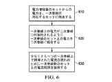
電力増幅器の或るセットからの電力を1次巻線の対応するセットに結合することであって、各1次巻線が前記電力増幅器の対応する1つからだけ直接に電力を受け取るように結合される、前記結合することと、
前記1次巻線上の電力が2次巻線において付加されるように前記1次巻線のセット上の前記電力を前記2次巻線に電磁気的に結合することと、
前記1次巻線に結合される電力増幅器が「オフ」状態にあるときに少なくとも1つの1次巻線上に誘導される第1の電流の流れのために前記1次巻線のセットを含むループとしての電流経路を提供することと、
を含み、
前記誘導された電流が、前記1次巻線に接続される電力増幅器が前記「オフ」状態にあるときに前記2次巻線を流れる電流によって1次巻線上に誘導され、
前記電流経路が第1の抵抗性ネットワークと第2の抵抗性ネットワークとを含み、前記第1の抵抗性ネットワークが、第1の共通端子と前記1次巻線のセットの正の端子のセットとの間に接続され、前記第2の抵抗性ネットワークが、第2の共通端子と前記1次巻線のセット上の負の端子のセットとの間に接続される、方法。 - 請求項7に記載の方法であって、
前記電力増幅器のセットが通信チャネルを介する伝送のため信号を増幅するように構成される、方法。 - 請求項8に記載の方法であって、
前記2次巻線が、前記1次巻線のセットから受信した電力の和に実質的に等しい送信電力で前記信号を伝送するように構成される、方法。 - 請求項9に記載の方法であって、
電力増幅器の第1のセットにおける「オン」状態と「オフ」状態との電力増幅器の比を変えることによって前記送信電力を変えることを更に含み、前記「オフ」状態電力増幅器がゼロ電力を前記対応する一次巻線に結合する、方法。 - 請求項10に記載の方法であって、
各電力増幅器が前記信号電力を最大送信電力の一部まで増幅するように構成される、方法。 - 請求項11に記載の方法であって、
前記1次巻線のセットが金属層上にエッチングされ、前記2次巻線が前記集積回路の再配線層上に形成される、方法。 - トランスミッタであって、
通信チャネルを介する伝送のため信号を増幅するように構成される電力増幅器のセットであって、前記電力増幅器のセットにおける各電力増幅器が、「オン」状態において動作されるときに前記信号の前記電力を送信電力の一部まで増幅し、そうでないときにゼロ電力まで増幅するように構成される、前記電力増幅器のセットと、
1次巻線のセットであって、各1次巻線が前記電力増幅器のセットにおける前記電力増幅器の対応する1つに結合される正及び負の端子を含む、前記1次巻線のセットと、
2次巻線であって、各1次巻線で受け取られる電力が前記2次巻線に付加的に搬送されるように、前記1次巻線のセットに電磁気的に結合される、前記2次巻線と、
前記1次巻線のセットの前記正の端子と第1の共通端子との間に結合される第1の抵抗と、
前記1次巻線のセットの前記負の端子と第2の共通端子との間に結合される第2の抵抗と、
を含み、
前記第1の抵抗と前記第2の抵抗とが前記電力増幅器のセットの外で電流経路を形成し、
前記対応する1次巻線に結合される電力増幅器が「オフ」状態にあるときに、少なくとも1つの1次巻線上に誘導される第1の電流が前記電流経路を介して流れる、トランスミッタ。 - 請求項13に記載のトランスミッタであって、
前記第1の抵抗と前記第2の抵抗とが、第1のレジスタネットワークと第2のレジスタネットワークとをそれぞれ含む、トランスミッタ。 - 請求項14に記載のトランスミッタであって、
前記1次巻線のセットが金属層上に形成され、前記2次巻線が前記集積回路の再配線層上に形成される、トランスミッタ。
Applications Claiming Priority (3)
| Application Number | Priority Date | Filing Date | Title |
|---|---|---|---|
| US14/165,251 US9450546B2 (en) | 2014-01-27 | 2014-01-27 | System, method and device for power amplification of a signal in an integrated circuit |
| US14/165,251 | 2014-01-27 | ||
| PCT/US2015/013148 WO2015113069A1 (en) | 2014-01-27 | 2015-01-27 | System, method and device for power amplification of a signal in an integrated circuit |
Publications (3)
| Publication Number | Publication Date |
|---|---|
| JP2017509224A JP2017509224A (ja) | 2017-03-30 |
| JP2017509224A5 JP2017509224A5 (ja) | 2018-03-01 |
| JP6741370B2 true JP6741370B2 (ja) | 2020-08-19 |
Family
ID=53680038
Family Applications (1)
| Application Number | Title | Priority Date | Filing Date |
|---|---|---|---|
| JP2016548635A Active JP6741370B2 (ja) | 2014-01-27 | 2015-01-27 | 集積回路における信号の電力増幅のためのシステム、方法、及びデバイス |
Country Status (4)
| Country | Link |
|---|---|
| US (1) | US9450546B2 (ja) |
| JP (1) | JP6741370B2 (ja) |
| CN (1) | CN106031029B (ja) |
| WO (1) | WO2015113069A1 (ja) |
Families Citing this family (6)
| Publication number | Priority date | Publication date | Assignee | Title |
|---|---|---|---|---|
| US10128875B1 (en) * | 2018-03-30 | 2018-11-13 | Mitsubishi Electric Research Laboratories, Inc. | Methods and system of a digital transmitter with reduced quantization noise |
| WO2022259892A1 (ja) * | 2021-06-10 | 2022-12-15 | 株式会社村田製作所 | 増幅回路及び高周波回路 |
| WO2023162655A1 (ja) * | 2022-02-24 | 2023-08-31 | 株式会社村田製作所 | ドハティ増幅回路 |
| US12482915B2 (en) | 2023-04-18 | 2025-11-25 | Apple Inc. | Transformer based series Doherty power amplifier |
| US20250047247A1 (en) * | 2023-08-04 | 2025-02-06 | Shenzhen MUYE Microelectronic Technologies Co., LTD | Transformer Power Combiner Apparatus and Control Method |
| WO2025243345A1 (ja) * | 2024-05-20 | 2025-11-27 | 株式会社ソシオネクスト | 出力合成用トランス回路 |
Family Cites Families (14)
| Publication number | Priority date | Publication date | Assignee | Title |
|---|---|---|---|---|
| FR1495534A (fr) | 1966-07-29 | 1967-09-22 | Thomson Houston Comp Francaise | Perfectionnements aux amplificateurs de puissance à transistors |
| JPS5992608A (ja) * | 1982-11-19 | 1984-05-28 | Oki Electric Ind Co Ltd | 電力増幅回路 |
| US4965530A (en) * | 1989-09-26 | 1990-10-23 | General Electric Company | Parallelled amplifier with switched isolation resistors |
| RU2117381C1 (ru) | 1997-03-12 | 1998-08-10 | Научно-производственное предприятие "Полет" | Усилитель мощности радиопередатчика |
| CN1116735C (zh) * | 1998-04-02 | 2003-07-30 | 艾利森公司 | 混合的Chireix/Doherty放大器功率波形综合 |
| US6294955B1 (en) | 2000-04-07 | 2001-09-25 | Harris Corporation | Apparatus and method for use in disconnecting and/or replacing one of a plurality of power amplifiers in a transmitter while the transmitter is operating |
| GB2439997A (en) * | 2006-07-07 | 2008-01-16 | Cambridge Semiconductor Ltd | Estimating the output current of a switch mode power supply |
| US7952433B2 (en) * | 2008-11-25 | 2011-05-31 | Samsung Electro-Mechanics Company | Power amplifiers with discrete power control |
| CN102459863A (zh) * | 2009-05-08 | 2012-05-16 | 费德罗-莫格尔点火公司 | 具有自调节功率放大器的电晕点火系统 |
| JP5459169B2 (ja) * | 2010-09-30 | 2014-04-02 | 富士通株式会社 | 増幅回路 |
| KR101197904B1 (ko) * | 2011-04-04 | 2012-11-05 | 삼성전기주식회사 | 전력 결합기, 이를 갖는 전력 증폭 모듈 및 신호 송수신 모듈 |
| US9306502B2 (en) * | 2011-05-09 | 2016-04-05 | Qualcomm Incorporated | System providing switchable impedance transformer matching for power amplifiers |
| JP5719259B2 (ja) * | 2011-09-06 | 2015-05-13 | ルネサスエレクトロニクス株式会社 | 高周波電力増幅装置 |
| JP5319006B2 (ja) * | 2012-10-10 | 2013-10-16 | ルネサスエレクトロニクス株式会社 | 電力増幅回路 |
-
2014
- 2014-01-27 US US14/165,251 patent/US9450546B2/en active Active
-
2015
- 2015-01-27 CN CN201580009878.4A patent/CN106031029B/zh active Active
- 2015-01-27 JP JP2016548635A patent/JP6741370B2/ja active Active
- 2015-01-27 WO PCT/US2015/013148 patent/WO2015113069A1/en not_active Ceased
Also Published As
| Publication number | Publication date |
|---|---|
| US9450546B2 (en) | 2016-09-20 |
| CN106031029A (zh) | 2016-10-12 |
| US20150214907A1 (en) | 2015-07-30 |
| JP2017509224A (ja) | 2017-03-30 |
| WO2015113069A1 (en) | 2015-07-30 |
| CN106031029B (zh) | 2019-10-22 |
Similar Documents
| Publication | Publication Date | Title |
|---|---|---|
| JP6741370B2 (ja) | 集積回路における信号の電力増幅のためのシステム、方法、及びデバイス | |
| US10608590B2 (en) | High-gain low noise figure low noise complementary metal oxide semiconductor amplifier with low current consumption | |
| US8031003B2 (en) | Solid-state RF power amplifier for radio transmitters | |
| US10536187B2 (en) | Complementary metal oxide semiconductor differential antenna transmit-receive switches with power combining circuitry for orthogonal frequency-division multiplexing systems | |
| US8570235B2 (en) | Systems and methods for complementary metal-oxide-semiconductor (CMOS) differential antenna switches using multi-section impedance transformations | |
| US9065541B2 (en) | Configurable wireless communication device with configurable front-end | |
| CN103546101A (zh) | 用于低噪声放大器的系统及方法 | |
| US8873339B2 (en) | Method and apparatus for a clock and signal distribution network for a 60 GHz transmitter system | |
| US11349469B2 (en) | High power radio frequency switches with low leakage current and low insertion loss | |
| CN103916090A (zh) | 多绕组变压器耦合的放大器 | |
| Cho et al. | A switchless CMOS bi-directional distributed gain amplifier with multi-octave bandwidth | |
| US8145160B2 (en) | Tx module for wireless communication | |
| JP2014179738A (ja) | 高周波広帯域増幅回路 | |
| US8198968B2 (en) | System and method for multiple band transmission | |
| US8242846B2 (en) | Power amplifier | |
| US8073417B2 (en) | Method and system for a transformer-based high performance cross-coupled low noise amplifier | |
| US8723602B2 (en) | Method and apparatus for a class-E load tuned beamforming 60 GHz transmitter | |
| US20180351517A1 (en) | Hybrid rf transceiver circuit | |
| Kang et al. | Differential transformer using bonder-wires and patterns on a printed circuit board for RF circuit applications | |
| WO2025064181A1 (en) | Interstage darlington circuit | |
| KR20200123571A (ko) | 전력 증폭기들 전단의 커플링 장치 | |
| WO2014025714A1 (en) | Method and apparatus for a class-e load tuned beamforming 60 ghz transmitter |
Legal Events
| Date | Code | Title | Description |
|---|---|---|---|
| A521 | Request for written amendment filed |
Free format text: JAPANESE INTERMEDIATE CODE: A821 Effective date: 20160727 |
|
| A521 | Request for written amendment filed |
Free format text: JAPANESE INTERMEDIATE CODE: A523 Effective date: 20180122 |
|
| A621 | Written request for application examination |
Free format text: JAPANESE INTERMEDIATE CODE: A621 Effective date: 20180122 |
|
| A977 | Report on retrieval |
Free format text: JAPANESE INTERMEDIATE CODE: A971007 Effective date: 20181226 |
|
| A131 | Notification of reasons for refusal |
Free format text: JAPANESE INTERMEDIATE CODE: A131 Effective date: 20190109 |
|
| A521 | Request for written amendment filed |
Free format text: JAPANESE INTERMEDIATE CODE: A523 Effective date: 20190407 |
|
| A131 | Notification of reasons for refusal |
Free format text: JAPANESE INTERMEDIATE CODE: A131 Effective date: 20190911 |
|
| A521 | Request for written amendment filed |
Free format text: JAPANESE INTERMEDIATE CODE: A523 Effective date: 20191024 |
|
| A02 | Decision of refusal |
Free format text: JAPANESE INTERMEDIATE CODE: A02 Effective date: 20200324 |
|
| A521 | Request for written amendment filed |
Free format text: JAPANESE INTERMEDIATE CODE: A523 Effective date: 20200621 Free format text: JAPANESE INTERMEDIATE CODE: A821 Effective date: 20200622 |
|
| A911 | Transfer to examiner for re-examination before appeal (zenchi) |
Free format text: JAPANESE INTERMEDIATE CODE: A911 Effective date: 20200630 |
|
| TRDD | Decision of grant or rejection written | ||
| A01 | Written decision to grant a patent or to grant a registration (utility model) |
Free format text: JAPANESE INTERMEDIATE CODE: A01 Effective date: 20200722 |
|
| A61 | First payment of annual fees (during grant procedure) |
Free format text: JAPANESE INTERMEDIATE CODE: A61 Effective date: 20200722 |
|
| R150 | Certificate of patent or registration of utility model |
Ref document number: 6741370 Country of ref document: JP Free format text: JAPANESE INTERMEDIATE CODE: R150 |
|
| S111 | Request for change of ownership or part of ownership |
Free format text: JAPANESE INTERMEDIATE CODE: R313117 |
|
| S111 | Request for change of ownership or part of ownership |
Free format text: JAPANESE INTERMEDIATE CODE: R313117 |
|
| S111 | Request for change of ownership or part of ownership |
Free format text: JAPANESE INTERMEDIATE CODE: R313117 |
|
| R350 | Written notification of registration of transfer |
Free format text: JAPANESE INTERMEDIATE CODE: R350 |
|
| R250 | Receipt of annual fees |
Free format text: JAPANESE INTERMEDIATE CODE: R250 |
|
| R250 | Receipt of annual fees |
Free format text: JAPANESE INTERMEDIATE CODE: R250 |
|
| R250 | Receipt of annual fees |
Free format text: JAPANESE INTERMEDIATE CODE: R250 |