JP6737212B2 - Driver state estimating device and driver state estimating method - Google Patents
Driver state estimating device and driver state estimating method Download PDFInfo
- Publication number
- JP6737212B2 JP6737212B2 JP2017048503A JP2017048503A JP6737212B2 JP 6737212 B2 JP6737212 B2 JP 6737212B2 JP 2017048503 A JP2017048503 A JP 2017048503A JP 2017048503 A JP2017048503 A JP 2017048503A JP 6737212 B2 JP6737212 B2 JP 6737212B2
- Authority
- JP
- Japan
- Prior art keywords
- driver
- head
- distance
- unit
- image
- Prior art date
- Legal status (The legal status is an assumption and is not a legal conclusion. Google has not performed a legal analysis and makes no representation as to the accuracy of the status listed.)
- Expired - Fee Related
Links
- 238000000034 method Methods 0.000 title claims description 65
- 238000003384 imaging method Methods 0.000 claims description 27
- 238000001514 detection method Methods 0.000 claims description 20
- 210000003128 head Anatomy 0.000 description 106
- 238000012545 processing Methods 0.000 description 14
- 238000010586 diagram Methods 0.000 description 8
- 238000004891 communication Methods 0.000 description 7
- 230000003287 optical effect Effects 0.000 description 5
- 230000006870 function Effects 0.000 description 4
- 238000005516 engineering process Methods 0.000 description 2
- 230000001815 facial effect Effects 0.000 description 2
- 230000015654 memory Effects 0.000 description 2
- 210000000056 organ Anatomy 0.000 description 2
- 238000001228 spectrum Methods 0.000 description 2
- 238000004364 calculation method Methods 0.000 description 1
- 230000003247 decreasing effect Effects 0.000 description 1
- 238000005315 distribution function Methods 0.000 description 1
- 210000005069 ears Anatomy 0.000 description 1
- 238000009434 installation Methods 0.000 description 1
- 238000012544 monitoring process Methods 0.000 description 1
- 230000002093 peripheral effect Effects 0.000 description 1
- 239000004065 semiconductor Substances 0.000 description 1
Images


Classifications
-
- G—PHYSICS
- G06—COMPUTING; CALCULATING OR COUNTING
- G06V—IMAGE OR VIDEO RECOGNITION OR UNDERSTANDING
- G06V20/00—Scenes; Scene-specific elements
- G06V20/50—Context or environment of the image
- G06V20/59—Context or environment of the image inside of a vehicle, e.g. relating to seat occupancy, driver state or inner lighting conditions
- G06V20/597—Recognising the driver's state or behaviour, e.g. attention or drowsiness
-
- B—PERFORMING OPERATIONS; TRANSPORTING
- B60—VEHICLES IN GENERAL
- B60W—CONJOINT CONTROL OF VEHICLE SUB-UNITS OF DIFFERENT TYPE OR DIFFERENT FUNCTION; CONTROL SYSTEMS SPECIALLY ADAPTED FOR HYBRID VEHICLES; ROAD VEHICLE DRIVE CONTROL SYSTEMS FOR PURPOSES NOT RELATED TO THE CONTROL OF A PARTICULAR SUB-UNIT
- B60W40/00—Estimation or calculation of non-directly measurable driving parameters for road vehicle drive control systems not related to the control of a particular sub unit, e.g. by using mathematical models
- B60W40/08—Estimation or calculation of non-directly measurable driving parameters for road vehicle drive control systems not related to the control of a particular sub unit, e.g. by using mathematical models related to drivers or passengers
-
- G—PHYSICS
- G06—COMPUTING; CALCULATING OR COUNTING
- G06T—IMAGE DATA PROCESSING OR GENERATION, IN GENERAL
- G06T7/00—Image analysis
- G06T7/50—Depth or shape recovery
- G06T7/529—Depth or shape recovery from texture
-
- G—PHYSICS
- G06—COMPUTING; CALCULATING OR COUNTING
- G06T—IMAGE DATA PROCESSING OR GENERATION, IN GENERAL
- G06T7/00—Image analysis
- G06T7/50—Depth or shape recovery
- G06T7/55—Depth or shape recovery from multiple images
- G06T7/571—Depth or shape recovery from multiple images from focus
-
- G—PHYSICS
- G06—COMPUTING; CALCULATING OR COUNTING
- G06V—IMAGE OR VIDEO RECOGNITION OR UNDERSTANDING
- G06V40/00—Recognition of biometric, human-related or animal-related patterns in image or video data
- G06V40/10—Human or animal bodies, e.g. vehicle occupants or pedestrians; Body parts, e.g. hands
- G06V40/16—Human faces, e.g. facial parts, sketches or expressions
- G06V40/161—Detection; Localisation; Normalisation
- G06V40/166—Detection; Localisation; Normalisation using acquisition arrangements
-
- B—PERFORMING OPERATIONS; TRANSPORTING
- B60—VEHICLES IN GENERAL
- B60W—CONJOINT CONTROL OF VEHICLE SUB-UNITS OF DIFFERENT TYPE OR DIFFERENT FUNCTION; CONTROL SYSTEMS SPECIALLY ADAPTED FOR HYBRID VEHICLES; ROAD VEHICLE DRIVE CONTROL SYSTEMS FOR PURPOSES NOT RELATED TO THE CONTROL OF A PARTICULAR SUB-UNIT
- B60W40/00—Estimation or calculation of non-directly measurable driving parameters for road vehicle drive control systems not related to the control of a particular sub unit, e.g. by using mathematical models
- B60W40/08—Estimation or calculation of non-directly measurable driving parameters for road vehicle drive control systems not related to the control of a particular sub unit, e.g. by using mathematical models related to drivers or passengers
- B60W2040/0818—Inactivity or incapacity of driver
- B60W2040/0827—Inactivity or incapacity of driver due to sleepiness
-
- B—PERFORMING OPERATIONS; TRANSPORTING
- B60—VEHICLES IN GENERAL
- B60W—CONJOINT CONTROL OF VEHICLE SUB-UNITS OF DIFFERENT TYPE OR DIFFERENT FUNCTION; CONTROL SYSTEMS SPECIALLY ADAPTED FOR HYBRID VEHICLES; ROAD VEHICLE DRIVE CONTROL SYSTEMS FOR PURPOSES NOT RELATED TO THE CONTROL OF A PARTICULAR SUB-UNIT
- B60W2420/00—Indexing codes relating to the type of sensors based on the principle of their operation
- B60W2420/40—Photo or light sensitive means, e.g. infrared sensors
- B60W2420/403—Image sensing, e.g. optical camera
-
- G—PHYSICS
- G06—COMPUTING; CALCULATING OR COUNTING
- G06T—IMAGE DATA PROCESSING OR GENERATION, IN GENERAL
- G06T2207/00—Indexing scheme for image analysis or image enhancement
- G06T2207/30—Subject of image; Context of image processing
- G06T2207/30196—Human being; Person
-
- G—PHYSICS
- G06—COMPUTING; CALCULATING OR COUNTING
- G06T—IMAGE DATA PROCESSING OR GENERATION, IN GENERAL
- G06T2207/00—Indexing scheme for image analysis or image enhancement
- G06T2207/30—Subject of image; Context of image processing
- G06T2207/30196—Human being; Person
- G06T2207/30201—Face
-
- G—PHYSICS
- G06—COMPUTING; CALCULATING OR COUNTING
- G06T—IMAGE DATA PROCESSING OR GENERATION, IN GENERAL
- G06T2207/00—Indexing scheme for image analysis or image enhancement
- G06T2207/30—Subject of image; Context of image processing
- G06T2207/30248—Vehicle exterior or interior
- G06T2207/30268—Vehicle interior
Description
本発明は運転者状態推定装置、及び運転者状態推定方法に関し、より詳細には、撮像された画像を用いて運転者の状態を推定することのできる運転者状態推定装置、及び運転者状態推定方法に関する。 The present invention relates to a driver state estimating device and a driver state estimating method, and more particularly, to a driver state estimating device and a driver state estimating device capable of estimating a driver state using a captured image. Regarding the method.
車室内カメラで撮影された運転者の画像から運転者の動作や視線などの状態を検知し、運転者に必要とされる情報の提示や警告などを行う技術が従来より開発されている。
また、近年開発が進められている自動運転システムでは、自動運転中においても、自動運転から手動運転への引き継ぎがスムーズに行えるように、運転者が運転操作可能な状態であるかどうかを推定しておく技術が必要になると考えられており、車室内カメラで撮像した画像を解析して、運転者の状態を推定する技術の開発が進められている。
2. Description of the Related Art A technique has been conventionally developed that detects a driver's motion and a state such as a line of sight from an image of a driver captured by a vehicle interior camera, and presents a driver with necessary information and a warning.
In addition, in the automatic driving system that has been developed in recent years, it is estimated whether or not the driver can perform driving operation so that the automatic driving can be smoothly transferred to the manual driving even during the automatic driving. It is considered necessary to have a technology for storing the information in advance, and the technology for estimating the state of the driver by analyzing the image captured by the vehicle interior camera is being developed.
運転者の状態を推定するためには、運転者の頭部位置を検出する技術が必要とされている。例えば、特許文献1には、車室内カメラで撮像された画像中における運転者の顔領域を検出し、検出した顔領域に基づいて、運転者の頭部位置を推定する技術が開示されている。
In order to estimate the driver's condition, a technique for detecting the driver's head position is required. For example,
上記運転者の頭部位置の具体的な推定方法は、まず、車室内カメラに対する頭部位置の角度を検出する。該頭部位置の角度の検出方法は、画像上での顔領域の中心位置を検出し、該検出した顔領域の中心位置を頭部位置として、該顔領域の中心位置を通る頭部位置直線を求め、該頭部位置直線の角度(頭部位置の車室内カメラに対する角度)を決定する。 The specific method of estimating the head position of the driver first detects the angle of the head position with respect to the vehicle interior camera. The method for detecting the angle of the head position is to detect the center position of the face area on the image, and use the detected center position of the face area as the head position, and pass the head position straight line passing through the center position of the face area. And the angle of the head position line (the angle of the head position with respect to the vehicle interior camera) is determined.
次に、頭部位置直線上の頭部位置を検出する。該頭部位置直線上の頭部位置の検出方法は、車室内カメラから所定距離に存在する場合の顔領域の標準大きさを記憶しておき、この標準大きさと実際に検出した顔領域の大きさとを比較して、車室内カメラから頭部位置までの距離を求める。そして、求めた距離だけ車室内カメラから離れた、頭部位置直線上の位置を頭部位置として推定するようになっている。 Next, the head position on the head position line is detected. The method of detecting the head position on the head position line is to store the standard size of the face area in the case of being present at a predetermined distance from the vehicle interior camera, and to store this standard size and the size of the actually detected face area. And the distance from the vehicle interior camera to the head position are obtained. Then, the position on the head position straight line, which is separated from the vehicle interior camera by the obtained distance, is estimated as the head position.
[発明が解決しようとする課題]
特許文献1記載の頭部位置の推定方法では、画像上での頭部位置を顔領域の中心位置を基準として検出しているが、顔領域の中心位置は顔の向きによって変わってしまう。そのため、頭の位置が同じ位置であっても、顔の向きの違いより、画像上で検出される顔領域の中心位置がそれぞれ異なる位置に検出される。そのため画像上における頭部位置が実世界の頭部位置とは異なる位置に検出されてしまい、実世界における頭部位置までの距離を精度よく推定できないという課題があった。
[Problems to be Solved by the Invention]
In the head position estimation method described in
本発明は上記課題に鑑みなされたものであって、画像中における運転者の顔領域の中心位置を検出することなく運転者の頭部までの距離を推定することができ、該推定された距離を前記運転者の状態判定に利用することができる運転者状態推定装置、及び運転者状態推定方法を提供することを目的としている。 The present invention has been made in view of the above problems, and it is possible to estimate the distance to the driver's head without detecting the center position of the driver's face region in the image, and the estimated distance It is an object of the present invention to provide a driver state estimation device and a driver state estimation method that can be used for determining the driver's state.
上記目的を達成するために本発明に係る運転者状態推定装置(1)は、撮像された画像を用いて運転者の状態を推定する運転者状態推定装置であって、
運転席に着座している運転者を撮像可能な撮像部と、
少なくとも1つのハードウェアプロセッサとを備え、
該少なくとも1つのハードウェアプロセッサが、
前記撮像部により撮像された画像中の運転者の頭部を検出する頭部検出部と、
該頭部検出部で検出された前記画像中の運転者の頭部のボケ量を検出するボケ量検出部と、
該ボケ量検出部で検出された前記ボケ量を用いて、前記運転席に着座している運転者の頭部から前記撮像部までの距離を推定する距離推定部とを備えていることを特徴としている。
In order to achieve the above object, a driver state estimation device (1) according to the present invention is a driver state estimation device that estimates a driver's state using a captured image,
An imaging unit capable of imaging the driver sitting in the driver's seat,
At least one hardware processor,
The at least one hardware processor is
A head detection unit that detects the driver's head in the image captured by the imaging unit;
A blur amount detecting unit that detects the amount of blur of the driver's head in the image detected by the head detecting unit;
A distance estimation unit that estimates the distance from the head of the driver sitting in the driver seat to the imaging unit using the blur amount detected by the blur amount detection unit. I am trying.
上記運転者状態推定装置(1)によれば、前記撮像部により撮像された前記運転者の画像を用いて、該画像中の運転者の頭部を検出し、該検出した前記画像中の運転者の頭部のボケ量を検出し、該ボケ量を用いて、前記運転席に着座している運転者の頭部から前記撮像部までの距離が推定される。したがって、前記画像中の顔領域の中心位置を求めることなく、前記画像中の前記運転者の頭部のボケ量から前記距離を推定することができる。該推定された距離を用いて、前記運転席に着座している運転者の位置姿勢などの状態を推定することが可能となる。 According to the driver state estimation device (1), the driver's head in the image is detected using the image of the driver captured by the image capturing unit, and the driver in the detected image is driven. The amount of blurring of the person's head is detected, and the distance from the head of the driver sitting in the driver's seat to the imaging unit is estimated using the amount of blurring. Therefore, the distance can be estimated from the blur amount of the driver's head in the image without obtaining the center position of the face area in the image. Using the estimated distance, it becomes possible to estimate the state such as the position and orientation of the driver sitting in the driver's seat.
また本発明に係る運転者状態推定装置(2)は、上記運転者状態推定装置(1)において、前記運転席に着座している運転者の頭部から前記撮像部までの距離と、前記撮像部で撮像される前記運転者の画像のボケ量との相関関係を示すテーブル情報を記憶するテーブル情報記憶部を備え、
前記距離推定部が、
前記ボケ量検出部で検出された前記ボケ量と、前記テーブル情報記憶部から読み出された前記テーブル情報とを照合して、前記運転席に着座している運転者の頭部から前記撮像部までの距離を推定するものであることを特徴としている。
The driver state estimating apparatus (2) according to the present invention is the driver state estimating apparatus (1), wherein the distance from the head of the driver sitting in the driver seat to the image capturing unit and the image capturing operation are performed. A table information storage unit that stores table information indicating a correlation with the amount of blur of the image of the driver captured by the unit,
The distance estimation unit,
The blur amount detected by the blur amount detecting unit is collated with the table information read from the table information storage unit, and the imaging unit is moved from the head of the driver seated in the driver seat. The feature is that it estimates the distance to.
上記運転者状態推定装置(2)によれば、前記テーブル情報記憶部に、前記撮像部で撮像される前記運転者の画像のボケ量と、前記運転者の頭部から前記撮像部までの距離との対応関係を示すテーブル情報が記憶され、前記ボケ量検出部で検出された前記ボケ量と、前記テーブル情報記憶部から読み出された前記テーブル情報とが照合されて、前記運転席に着座している運転者の頭部から前記撮像部までの距離が推定される。したがって、前記テーブル情報に前記ボケ量を当てはめることにより、前記運転席に着座している運転者の頭部から前記撮像部までの距離を、演算処理に負荷をかけることなく高速に推定することができる。 According to the driver state estimating device (2), in the table information storage unit, the blur amount of the image of the driver captured by the image capturing unit and the distance from the driver's head to the image capturing unit. Table information indicating a correspondence relationship with the table is stored, and the blur amount detected by the blur amount detection unit and the table information read from the table information storage unit are collated to sit in the driver's seat. The distance from the driver's head to the imaging unit is estimated. Therefore, by applying the blur amount to the table information, the distance from the head of the driver sitting in the driver seat to the imaging unit can be estimated at high speed without burdening the calculation process. it can.
また本発明に係る運転者状態推定装置(3)は、上記運転者状態推定装置(1)又は(2)において、前記距離推定部が、前記撮像部により撮像された複数の画像から検出された前記運転者の顔領域の大きさの変化を考慮して、前記運転席に着座している運転者の頭部から前記撮像部までの距離を推定するものであることを特徴としている。 In the driver state estimating device (3) according to the present invention, in the driver state estimating device (1) or (2), the distance estimating unit is detected from a plurality of images captured by the image capturing unit. The distance from the head of the driver sitting in the driver's seat to the imaging unit is estimated in consideration of the change in the size of the driver's face area.
上記運転者状態推定装置(3)によれば、前記運転者の顔領域の大きさの変化を考慮することにより、前記撮像部のピントが合う焦点位置から前後いずれの方向に前記運転者が離れているのかを判定することができるので、前記距離の推定精度を高めることができる。 According to the driver state estimation device (3), the driver moves away from the focus position of the image capturing unit in the front or back direction by considering the change in the size of the face area of the driver. Since it is possible to determine whether the distance is present, it is possible to improve the accuracy of estimating the distance.
また本発明に係る運転者状態推定装置(4)は、上記運転者状態推定装置(1)〜(3)のいずれかにおいて、前記少なくとも1つのハードウェアプロセッサが、
前記距離推定部で推定された前記距離を用いて、前記運転席に着座している運転者が運転操作可能な状態であるか否かを判定する運転操作可否判定部を備えていることを特徴としている。
A driver state estimation device (4) according to the present invention is the driver state estimation device (1) to (3), wherein the at least one hardware processor is
Using the distance estimated by the distance estimation unit, a driving operation propriety determination unit for determining whether or not a driver seated in the driver seat is in a state capable of driving operation is provided. I am trying.
上記運転者状態推定装置(4)によれば、前記距離推定部で推定された前記距離を用いて、前記運転席に着座している運転者が運転操作可能な状態であるか否かを判定することができ、前記運転者の監視を適切に行うことができる。 According to the driver state estimating device (4), it is determined whether or not the driver seated in the driver seat is in a drive-operable state by using the distance estimated by the distance estimating unit. It is possible to properly monitor the driver.
また本発明に係る運転者状態推定装置(5)は、上記運転者状態推定装置(1)〜(4)のいずれかにおいて、前記撮像部が、前記運転席に着座している運転者の位置姿勢の変化に応じて前記運転者の頭部のボケ具合が異なる画像を撮像可能なものであることを特徴としている。 The driver state estimating apparatus (5) according to the present invention is the driver state estimating apparatus (1) to (4) according to any one of the driver state estimating apparatuses, wherein the imaging unit is the position of the driver sitting in the driver seat. It is characterized in that an image in which the degree of blurring of the driver's head varies depending on the change in posture can be captured.
上記運転者状態推定装置(5)によれば、前記運転席という限られた空間であっても、前記運転者の頭部のボケ具合が異なる画像が撮像可能であるので、前記ボケ量から前記距離を確実に推定することができる。 According to the driver state estimation device (5), even in the limited space of the driver's seat, it is possible to capture images with different degrees of blurring of the driver's head. The distance can be estimated reliably.
また本発明に係る運転者状態推定方法は、運転席に着座している運転者を撮像可能な撮像部と、少なくとも1つのハードウェアプロセッサとを備えた装置を用い、
前記運転席に着座している運転者の状態を推定する運転者状態推定方法であって、
前記少なくとも1つのハードウェアプロセッサが、
前記撮像部により撮像された画像中の運転者の頭部を検出する頭部検出ステップと、
該頭部検出ステップで検出された前記画像中の運転者の頭部のボケ量を検出するボケ量検出ステップと、
該ボケ量検出ステップで検出された前記ボケ量を用いて、前記運転席に着座している運転者の頭部から前記撮像部までの距離を推定する距離推定ステップとを含んでいることを特徴としている。
Further, a driver state estimation method according to the present invention uses an apparatus including an image capturing unit capable of capturing an image of a driver seated in a driver's seat, and at least one hardware processor.
A driver state estimation method for estimating the state of a driver sitting in the driver's seat,
The at least one hardware processor is
A head detecting step of detecting the driver's head in the image captured by the image capturing unit;
A blur amount detecting step of detecting a blur amount of the driver's head in the image detected in the head detecting step,
A distance estimation step of estimating a distance from the head of the driver seated in the driver seat to the imaging unit using the blur amount detected in the blur amount detection step. I am trying.
上記運転者状態推定方法によれば、前記撮像部により撮像された前記運転者の画像を用いて、該画像中の運転者の頭部を検出し、該検出した前記画像中の運転者の頭部のボケ量を検出し、該ボケ量を用いて、前記運転席に着座している運転者の頭部から前記撮像部までの距離を推定する。したがって、前記画像中の顔領域の中心位置を求めることなく、前記画像中の前記運転者の頭部のボケ量から前記距離を推定することができる。該推定された距離を用いて、前記運転席に着座している運転者の位置姿勢などの状態を推定することが可能となる。 According to the driver state estimating method, the head of the driver in the image is detected by using the image of the driver captured by the image capturing unit, and the head of the driver in the detected image is detected. The amount of blurring of the portion is detected, and the distance from the head of the driver sitting in the driver seat to the image capturing unit is estimated using the amount of blurring. Therefore, the distance can be estimated from the blur amount of the driver's head in the image without obtaining the center position of the face area in the image. Using the estimated distance, it becomes possible to estimate the state such as the position and orientation of the driver sitting in the driver's seat.
以下、本発明に係る運転者状態推定装置、及び運転者状態推定方法の実施の形態を図面に基づいて説明する。なお、以下に述べる実施の形態は、本発明の好適な具体例であり、技術的に種々の限定が付されているが、本発明の範囲は、以下の説明において特に本発明を限定する旨の記載がない限り、これらの形態に限られるものではない。 Embodiments of a driver state estimation device and a driver state estimation method according to the present invention will be described below with reference to the drawings. The embodiments described below are preferred specific examples of the present invention, and various technical limitations are attached thereto. However, the scope of the present invention specifically limits the present invention in the following description. Unless otherwise stated, the present invention is not limited to these forms.
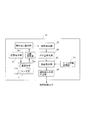
図1は、実施の形態に係る運転者状態推定装置を含む自動運転システムの要部を概略的に示したブロック図である。図2は、実施の形態に係る運転者状態推定装置の構成を示すブロック図である。 FIG. 1 is a block diagram schematically showing a main part of an automatic driving system including a driver state estimation device according to an embodiment. FIG. 2 is a block diagram showing the configuration of the driver state estimation device according to the embodiment.
自動運転システム1は、車両を道路に沿って自動で走行させるためのシステムであり、運転者状態推定装置10、HMI(Human Machine Interface)40、及び自動運転制御装置50を含んで構成され、これら各装置が通信バス60を介して接続されている。なお、通信バス60には、自動運転や運転者による手動運転の制御に必要な各種センサや制御装置(図示せず)も接続されている。
The
運転者状態推定装置10は、撮像された画像から運転者の状態、具体的には、撮像された画像中の運転者の頭部のボケ量を検出し、単眼カメラ11から運転者の頭部(顔)までの距離を前記ボケ量から推定する処理、前記距離の推定結果に基づいて運転者が運転操作可能な状態であるか否かを判定し、その判定結果を出力する処理などを行う。
The driver
運転者状態推定装置10は、単眼カメラ11、CPU12、ROM13、RAM14、記憶部15、及び入出力インターフェース(I/F)16を含んで構成され、これら各部が通信バス17を介して接続されている。なお、単眼カメラ11は、装置本体とは別体のカメラユニットとして構成してもよい。
The driver
撮像部としての単眼カメラ11は、運転席に着座している運転者の頭部を含む画像を定期的(例えば、1秒間に30〜60回)に撮像可能な単眼カメラであり、1枚以上のレンズから構成されるレンズ系11a、被写体の撮像データを生成するCCD又はCMOSなどの撮像素子11b、撮像データをデジタルデータに変換するAD変換部(図示せず)、及び近赤外光を照射する近赤外LEDなどの赤外線照射器(図示せず)などを含んで構成されている。
The
また、単眼カメラ11のレンズ系11aには、運転席の可動範囲内のいずれかの位置で運転者にピントが合い、かつ被写界深度が浅く(ピントの合う範囲が狭く)なるように、レンズの焦点距離及び絞り(F値)などの光学パラメータが設定されているものが使用される。これら光学パラメータの設定により、運転席に着座している運転者の位置姿勢の変化、例えば、運転席の座面位置や背もたれの傾きの変化に応じて運転者の頭部のボケ具合が異なる画像(運転者にピントの合った画像から徐々にピントのずれたボケ具合の異なる画像)を撮像可能となっている。なお、前記被写界深度は、後述する頭部検出部23における処理性能、すなわち、画像中から運転者の頭部や顔器官を検出する性能を妨げないように、頭部検出部23における処理性能のボケ許容範囲内において極力浅くなるように設定にすることが好ましい。
Further, the
CPU12は、ハードウェアプロセッサであり、ROM13に記憶されているプログラムを読み出し、該プログラムに基づいて単眼カメラ11で撮像された画像データの各種処理などを行う。CPU12は、画像処理や制御信号出力処理などの処理用途毎に複数装備してもよい。
ROM13には、図2に示す記憶指示部21、読み出し指示部22、頭部検出部23、ボケ量検出部24、距離推定部25、及び運転操作可否判定部26としての処理を、CPU12に実行させるためのプログラムなどが記憶されている。なお、CPU12で実行される前記プログラムの全部又は一部をROM13とは別の記憶部15や他の記憶媒体(図示せず)に記憶してもよい。
The
In the
RAM14には、CPU12で実行される各種処理に必要なデータやROM13から読み出したプログラムなどが一時記憶される。
記憶部15は、単眼カメラ11で撮像された画像データが記憶される画像記憶部15aと、単眼カメラ11から被写体(運転者)までの距離と単眼カメラ11で撮像される被写体の画像のボケ量との相関関係を示すテーブル情報が記憶されるテーブル情報記憶部15bとを含んでいる。また、記憶部15には、単眼カメラ11の焦点距離や絞り(F値)、画角や画素数(幅×縦)などを含むパラメータ情報、単眼カメラ11の取付位置情報なども記憶されるようになっている。単眼カメラ11の取付位置情報などは、例えば、単眼カメラ11の設定メニューをHMI40で読み出せるように構成しておき、取付時に、前記設定メニューから入力設定できるようにすればよい。記憶部15は、例えば、EEPROM、フラッシュメモリなどの1つ以上の不揮発性の半導体メモリで構成されている。入出力インターフェース(I/F)16は、通信バス60を介して各種外部装置とのデータのやり取りを行うためのものである。
The
The
HMI40は、運転者状態推定装置10から送信されてきた信号に基づいて、運転者に運転姿勢等の状態を報知する処理、自動運転システム1の作動状況や自動運転の解除情報などを運転者に報知する処理、自動運転制御に関連する操作信号を自動運転制御装置50に出力する処理などを行う。HMI40は、例えば、運転者が視認しやすい位置に設けられた表示部41や音声出力部42の他、図示しない操作部や音声入力部などを含んで構成されている。
The
自動運転制御装置50は、図示しない動力源制御装置、操舵制御装置、制動制御装置、周辺監視センサ、ナビゲーションシステム、外部と通信を行う通信装置などにも接続され、これら各部から取得した情報に基づいて、自動運転を行うための制御信号を各制御装置へ出力して、車両の自動走行制御(自動操舵制御や自動速度調整制御など)を行う。
The automatic
図2に示した運転者状態推定装置10の各部を説明する前に、図3を用いて、運転席の座席位置と、単眼カメラ11で撮像される画像中の運転者のボケ具合との関係について説明する。図3は、運転席の座席位置の違いによって画像中の運転者のボケ具合が変化することを説明するためのイラスト図である。
Before explaining each part of the driver
図3に示すように、運転者30が運転席31に着座しているとする。運転席31の正面前方にはハンドル32が設置されている。運転席31は、前後方向に位置調整可能となっており、座面の可動範囲がSに設定されている。単眼カメラ11は、ハンドル32の奥側(図示しないステアリングコラム、又はダッシュボードやインストルメントパネルの手前)に設けられており、運転者30Aの頭部(顔)を含む画像11cを撮像可能な箇所に設置されている。なお、単眼カメラ11の設置位置姿勢はこの形態に限定されるものではない。
As shown in FIG. 3, it is assumed that the
図3では、単眼カメラ11から実世界における運転者30までの距離をZ(Zf、Zblur)、ハンドル32から運転者30までの距離をA、ハンドル32から単眼カメラ11までの距離をB、単眼カメラ11の画角をα、撮像面の中心をIで示している。
図3(b)は、運転席31を可動範囲Sの略中間位置SMにセットした状態を示している。この状態では、運転者30の頭部(頭部正面の顔)の位置が、単眼カメラ11のピントが合う焦点位置(距離Zf)になっており、画像11cには、運転者30Aがピントの合ったボケのない状態で写されている。
In FIG. 3, the distance from the
FIG. 3B shows a state where the driver's
図3(a)は、運転席31を可動範囲Sの後方位置SBにセットした状態を示している。
運転者30の頭部の位置は、単眼カメラ11のピントが合う焦点位置(距離Zf)よりも遠い位置(ピントがずれた位置)(距離Zblur)にあるため、画像11cには、運転者30Aが中間位置SMよりも少し小さく、かつボケが生じた状態で写されている。
FIGS. 3 (a) shows a state that sets driver's
Since the position of the head of the
図3(c)は、運転席31を可動範囲Sの前方位置SFにセットした状態を示している。
運転者30の頭部の位置は、単眼カメラ11のピントが合う焦点位置(距離Zf)よりも近い位置(ピントがすれた位置)(距離Zblur)にあるため、画像11cには、運転者30Aが中間位置SMよりも少し大きく、かつボケが生じた状態で写されている。
FIG. 3 (c) shows a state that sets driver's
Since the position of the head of the
このように単眼カメラ11は、運転席31を略中間位置SMにセットした状態で運転者30の頭部にピントが合う一方、略中間位置SMよりも前後に運転席31をセットした状態では、運転者30の頭部にピントが合わず、画像中の運転者30Aの頭部には、ピント位置からのずれ量に応じたボケが生じる設定になっている。
State This
なお、上記形態では、運転席31を略中間位置SMにセットしたときの運転者30の頭部にピントが合うように単眼カメラ11の光学パラメータが設定されているが、単眼カメラ11のピントを合わせる位置は、この位置に限定されるものではない。運転席31を可動範囲Sのいずれかの位置にセットしたときの運転者30の頭部にピントが合うように、単眼カメラ11の光学パラメータを設定することができる。
In the above embodiment, the optical parameters of the
次に、実施の形態に係る運転者状態推定装置10の具体的構成について図2に示したブロック図に基づいて説明する。
運転者状態推定装置10は、ROM13に記憶された各種のプログラムがRAM14に読み出され、CPU12で実行されることによって、記憶指示部21、読み出し指示部22、頭部検出部23、ボケ量検出部24、距離推定部25、及び運転操作可否判定部26としての処理を行う装置として成立する。
Next, a specific configuration of the driver
In the driver
記憶指示部21は、単眼カメラ11で撮像された運転者30Aの頭部(顔)を含む画像データを記憶部15の一部である画像記憶部15aに記憶させる処理を行う。読み出し指示部22は画像記憶部15aから運転者30Aが撮像された画像11cを読み出す処理を行う。
The
頭部検出部23は、画像記憶部15aから読み出された画像11cから運転者30Aの頭部(顔)を検出する処理を行う。画像11cから頭部(顔)を検出する手法は特に限定されない。例えば、頭部(顔全体)の輪郭に対応した基準テンプレートを用いたテンプレートマッチング、頭部(顔)の構成要素(目、鼻、耳など)に基づくテンプレートマッチングによって頭部(顔)を検出するように構成してもよい。また、高速で高精度に頭部(顔)を検出する手法として、例えば、顔の局所的な領域、例えば、目の端点や口の端点、鼻の穴回りなどの顔器官の明暗差(輝度差)やエッジ強度、これら局所的領域間の関連性(共起性)を特徴量として捉え、これら多数の特徴量を組み合わせて学習することで検出器を作成し、階層的な構造(顔をおおまかにとらえる階層から顔の細部をとらえる階層構造)の検出器を用いる方法により、顔の領域検出を高速に行うことが可能となる。また、顔のボケ具合の違い、顔の向きや傾きに対応するために、顔のボケ具合、顔の向きや傾きごとに別々に学習させた複数の検出器を備えるようにしてもよい。
The
ボケ量検出部24は、頭部検出部23で検出された画像11c中の運転者30Aの頭部のボケ量を検出する処理を行う。画像中の運転者30A(被写体)のボケ量を検出する方法には、公知の手法が採用され得る。
例えば、撮像画像を分析することでボケ量を求める方法(非特許文献1参照)、画像の対数振幅スペクトル上に現れる暗い円環の半径から、ボケの特性を表現するPSF(Point Spread Function:点像分布関数)の推定を行う方法(非特許文献2参照)、画像の対数振幅スペクトル上の輝度こう配のベクトル分布を用いてボケの特性を表現し、PSFの推定を行う方法(非特許文献3)などを採用することができる。
The blur
For example, a method of obtaining a blur amount by analyzing a captured image (see Non-Patent Document 1), a PSF (Point Spread Function) that expresses the characteristic of blur from the radius of a dark ring appearing on the logarithmic amplitude spectrum of the image. Image distribution function) (see Non-Patent Document 2), a method of expressing the characteristics of blur using a vector distribution of the luminance gradient on the logarithmic amplitude spectrum of the image, and estimating the PSF (
また、撮像された画像を処理して被写体までの距離を測定する方法として、合焦位置に応じた画像ボケに着目するDFD(Depth from Defocus)法やDFF(Depth from Focus)法が知られている。DFD法は、焦点位置の異なる複数の画像を撮影して、光学ボケのモデル関数でボケ量をフィッティングし、ボケ量の変化から被写体に最もピントが合う位置を推定することで被写体までの距離を求める方法である。DFF法は、焦点位置をずらしながら撮影した多数の画像列の中で、最もピントの合った画像位置から距離を求める方法である。これら方法を利用してボケ量を推定することも可能である。 In addition, as a method for processing a captured image and measuring a distance to a subject, a DFD (Depth from Defocus) method and a DFF (Depth from Focus) method, which focus on image blur depending on a focus position, are known. There is. The DFD method captures a plurality of images with different focus positions, fits the blur amount with a model function of optical blur, and estimates the position at which the subject is most in focus from the change in the blur amount to determine the distance to the subject. It is a method of seeking. The DFF method is a method for obtaining the distance from the image position that is most in focus among a large number of image sequences that are taken while shifting the focus position. It is also possible to estimate the blur amount using these methods.
例えば、画像中のボケが薄レンズモデルに従うと仮定すると、ボケ量は上記点像分布関数(PSF)としてモデル化できる。一般にこのモデルとしてガウス関数が用いられる。これらを利用して、撮像された1枚又は2枚のボケを含んだ画像のエッジを解析しボケ量を推定する方法(非特許文献4)、撮像されたボケを含む画像(入力画像)と該入力画像を再度ぼかした平滑化画像とのエッジの潰れ方(エッジ強度の変化度合)を解析することによってボケ量を推定する方法(非特許文献5)などを採用することができる。また、非特許文献6には、DFD法がステレオ法と同じような仕組みで物体までの距離を測定できることが開示され、物体の画像が撮像素子面に投影されたときのブラー(ボケ)の円の半径を求める方法などが開示されている。これらDFD法などは、画像のボケ量と被写体距離との相関情報から距離を測定するものであり、単眼カメラ11を用いて実現可能である。これら方法を使用して、画像のボケ量を検出することができる。
For example, assuming that the blur in the image follows a thin lens model, the blur amount can be modeled as the above point spread function (PSF). A Gaussian function is generally used as this model. Using these, a method of analyzing the edge of an image including one or two captured blurs and estimating the amount of blur (Non-Patent Document 4), an image including the captured blur (input image), and A method (Non-Patent Document 5) or the like that estimates the amount of blur by analyzing how the edges are collapsed (degree of change in edge strength) with the smoothed image obtained by blurring the input image again can be adopted. Further, Non-Patent Document 6 discloses that the DFD method can measure the distance to an object by a mechanism similar to the stereo method, and a circle of blur (blur) when an image of the object is projected on the image pickup element surface. A method for obtaining the radius of the is disclosed. The DFD method and the like measure the distance from the correlation information between the image blur amount and the subject distance, and can be realized by using the
図4は、ボケ量検出部24で検出されるボケ量dと運転者30までの距離との関係(DFD法又はDFF法の仕組み)について説明するための図である。
図4において、fはレンズ系11aと撮像素子11bとの距離、Zfはピントの合う焦点(フォーカス点)と撮像素子11bとの距離、Zblurはボケの生じている(デフォーカスされている)運転者30(被写体)と撮像素子11bとの距離、Fはレンズの焦点距離、Dはレンズ系11aの口径、dは被写体の画像が撮像素子に投影されたときのブラー(ボケ)の円(錯乱円)の半径であり、半径dがボケ量に相当する。
ボケ量dは、以下の式で示すことができる。
FIG. 4 is a diagram for explaining the relationship between the blur amount d detected by the blur
In FIG. 4, f is the distance between the
The blur amount d can be expressed by the following formula.

なお、実線で示す光線L1は、ピントの合う焦点位置に運転者30がいるとき(図3(b)の状態)の光線を示している。一点鎖線で示す光線L2は、単眼カメラ11からの距離がピントの合う焦点位置よりも遠い位置に運転者30がいるとき(図3(a)の状態)の光線を示している。破線で示す光線L3は、単眼カメラ11からの距離がピントの合う焦点位置より近い位置に運転者30がいるとき(図3(c)状態)の光線を示している。
The light ray L1 indicated by the solid line indicates the light ray when the
上記式は、ボケ量dと、ボケが生じているときの距離Zblurとが相関関係を有していることを示している。本実施の形態では、単眼カメラ11で撮像される被写体の画像のボケ量dと、単眼カメラ11から被写体までの距離Zとの相関関係を示すテーブル情報が予め作成されて、テーブル情報記憶部15bに記憶されている。
The above equation indicates that the blur amount d and the distance Z blur when blurring have a correlation. In the present embodiment, table information indicating the correlation between the blur amount d of the image of the subject captured by the
図5は、テーブル情報記憶部15bに記憶されているボケ量dと距離Zとの相関関係を示すテーブル情報の一例を示したグラフ図である。
ピントの合う焦点位置の距離Zfで、ボケ量dは略0となっている。運転者30までの距離Zがピントの合う焦点位置の距離Zfから外れる(距離Zblurに移動する)につれてボケ量dが大きくなる。運転席31の可動範囲Sで、ボケ量dが検出できるように、レンズ系11aの焦点距離や絞りの設定がなされている。なお、図5に破線で示すように、単眼カメラ11のレンズ系11aの焦点距離を大きく、又は絞りを開く(F値を小さくする)設定にすることで、ピント位置からのボケ量の変化を大きくすることができる。
FIG. 5 is a graph showing an example of table information showing the correlation between the blur amount d and the distance Z stored in the table
The blur amount d is substantially zero at the distance Zf between the focused focal points. The blur amount d increases as the distance Z to the
距離推定部25は、ボケ量検出部24で検出されたボケ量dを用いて、運転席31に着座している運転者30の頭部から単眼カメラ11までの距離Z(奥行きに関する情報)を推定する処理を行う。すなわち、ボケ量検出部24で検出されたボケ量dを、上記したテーブル情報記憶部15bに記憶されたテーブル情報に当てはめて、運転席31に着座している運転者30の頭部から単眼カメラ11までの距離Zを推定する処理を行う。また、ボケ量検出部24において、頭部検出部23により検出された顔器官の特徴点部分、例えば、目の端点や口の端点、鼻の穴周りなどのコントラストがはっきりした特徴点部分のボケ量dを検出し、該ボケ量dを距離推定部25での推定処理に用いることにより、距離推定が容易になるとともに、距離推定の精度も高めることができる。
また、ボケ量dからでは、ピントの合う焦点位置(距離Zfの位置)から前後いずれの方向に外れているのかの判定が難しい場合は、時系列で取得した複数の画像中から運転者の顔領域の大きさを検出し、顔領域の大きさの変化(大きくなっていれば単眼カメラ11に近づいている一方、小さくなっていれば単眼カメラ11から離れている)を検出することによって、前記いずれの方向に外れているのかを判定することができる。また、前記テーブル情報の代わりに、ボケ量dと距離Zとの相関関係を示す式を用いて、ボケ量dから距離Zを求めてもよい。
The
Further, when it is difficult to determine from the focus amount (the position of the distance Zf) which is out of focus from the focus position (the position of the distance Zf) from the blur amount d, the face of the driver is selected from the plurality of images acquired in time series. By detecting the size of the area and detecting the change in the size of the face area (when it is large, the
運転操作可否判定部26は、距離推定部25で推定された距離Zを用いて、運転者30が運転操作可能な状態であるか否か、例えば、ROM13又は記憶部15に記憶された、ハンドルに手が届く範囲をRAM14に読み出し、比較演算を行うことにより、運転者30がハンドル32に手が届く範囲内にいるか否かを判定し、該判定結果を示す信号をHMI40や自動運転制御装置50へ出力する。また、距離Zから距離B(ハンドル32から単眼カメラ11までの距離)を引き、距離A(ハンドル32から運転者30までの距離)を求めて、上記判定を行ってもよい。
The driving operation
図6は、実施の形態に係る運転者状態推定装置10におけるCPU12の行う処理動作を示したフローチャートである。単眼カメラ11では、例えば、毎秒30〜60フレームの画像が撮像され、各フレーム、又は一定間隔のフレーム毎に本処理が行われる。
FIG. 6 is a flowchart showing a processing operation performed by the
まず、ステップS1では、単眼カメラ11で撮像された1つ以上の画像データを画像記憶部15aから読み出し、ステップS2で、読み出した1つ以上の画像11cから運転者30Aの頭部(顔)領域を検出する処理を行う。
First, in step S1, one or more image data captured by the
ステップS3では、画像11c中における運転者30Aの頭部のボケ量d、例えば、頭部領域の各画素のボケ量d、又は頭部のエッジ領域の各画素のボケ量dを検出する処理を行う。ボケ量dの検出処理は上記手法が採用され得る。
In step S3, a process of detecting the blur amount d of the head of the
ステップS4では、画像11c中の運転者30Aの頭部のボケ量dを用いて、運転者30の頭部から単眼カメラ11までの距離Zを推定する。すなわち、テーブル情報記憶部15bから読み出した上記テーブル情報と、検出したボケ量dとを照合して、ボケ量dに対応する単眼カメラ11からの距離Zを決定する。また、距離Zを推定する際に、単眼カメラ11により撮像された複数の画像(時系列の画像)から運転者の顔領域の大きさの変化を検出し、単眼カメラ11のピントが合う焦点位置から前後いずれの方向に運転者が離れているのかを判定し、該判定結果とボケ量dとを用いて、距離Zを推定してもよい。
In step S4, the distance Z from the head of the
ステップS5では、距離Zを用いて、ハンドル32位置から運転者30の頭部までの距離Aを推定する。例えば、単眼カメラ11と運転者30との線分上にハンドル32がある場合、距離Zから単眼カメラ11とハンドル32との距離Bを引くことで、距離Aを推定する。
In step S5, the distance A is estimated from the position of the
ステップS6では、RAM13又は記憶部15に記憶された、ハンドルに手が届く範囲を読み出し、比較演算を行うことにより、距離Aが、適切なハンドル操作が可能な範囲内(距離D1<距離A<距離D2)であるか否かを判定する。距離D1からD2の距離範囲は、運転者30が運転席31に着座した状態で、ハンドル32の操作が可能と推定される距離範囲、例えば、D1は40cm、距離D2は80cm程度の値に設定することができる。
In step S6, the range within which the handle can be reached, which is stored in the
ステップS6において、距離Aが適切なハンドル操作が可能な範囲内であると判断すれば、その後処理を終える一方、距離Aが適切なハンドル操作が可能な範囲内ではないと判断すればステップS7に進む。 If it is determined in step S6 that the distance A is within the range in which the appropriate steering wheel operation is possible, then the process is ended, while if it is determined that the distance A is not in the range in which the appropriate steering wheel operation is possible, the process proceeds to step S7. move on.
ステップS7では、HMI40や自動運転制御装置50に運転操作不可信号を出力し、その後処理を終える。HMI40では、運転操作不可信号を入力した場合、例えば、表示部41に運転姿勢や座席位置を警告する表示や、音声出力部42より運転姿勢や座席位置を警告するアナウンスを実行する。また、自動運転制御装置50では、運転操作不可信号を入力した場合、例えば、減速制御などを実行する。
In step S7, a driving operation disabling signal is output to the
なお、上記ステップS5、S6の処理に代えて、RAM13又は記憶部15に記憶された、適切なハンドル操作が可能な範囲を読み出し、比較演算を行うことにより、距離Zが、適切なハンドル操作が可能と推定する範囲内(距離E1<距離Z<距離E2)であるか否かを判定する処理を行ってもよい。
この場合、距離E1、E2は、例えば、上記した距離D1、D2に、ハンドル32から単眼カメラ11までの距離Bを加算した値とすればよい。距離E1、E2の距離範囲は、運転者30が運転席31に着座した状態で、ハンドル32の操作が可能と推定される距離範囲、例えば、距離E1は(40+距離B)cm、距離E2は(80+距離B)cm程度の値に設定することができる。
In place of the processing of steps S5 and S6, a range in which an appropriate steering wheel operation is stored, which is stored in the
In this case, the distances E 1 and E 2 may be, for example, values obtained by adding the distance B from the
また、上記ステップS4、5、6に代えて、ボケ量検出部24で検出されたボケ量dが、所定範囲内のボケ量(ボケ量d1<ボケ量d<ボケ量d2)であるか否かにより、運転者が運転操作可能な位置にいるか否かを判断する処理を行ってもよい。
この場合、上記距離Z、又は距離Aがハンドル操作可能と推定される範囲内(上記距離E1から距離E2、又は上記距離D1から距離D2)でのボケ量(距離E1、D1のときのボケ量d1、距離E1、D2ときのボケ量d2を含む)を予め作成したテーブル情報をテーブル情報記憶部15bに記憶しておき、上記判定時にボケ量のテーブル情報を読み出し、比較演算を行って判定するようにすればよい。
Further, the blur amount d detected by the blur
In this case, the amount of blurring (distances E 1 and D 2 ) within the range in which the distance Z or the distance A is estimated to be steerable (distance E 1 to distance E 2 or distance D 1 to distance D 2 ). blur amount d 1 when the 1, the distance E 1, D 2 comprises a blur amount d 2 when) stores the previously prepared table information in the table
実施の形態に係る運転者状態推定装置10によれば、単眼カメラ11により撮像された運転者30の頭部のボケ具合の異なる画像を用いて、画像11c中の運転者30Aの頭部を検出し、該検出した画像11c中の運転者30Aの頭部のボケ量を検出し、該ボケ量を用いて、運転席31に着座している運転者30の頭部から単眼カメラ11までの距離Zが推定される。したがって、画像11c中の顔領域の中心位置を求めることなく、画像11c中の運転者30Aの頭部のボケ量dから距離Zを推定することができ、該推定された距離Zを用いて、運転席31に着座している運転者30の位置姿勢などの状態を推定することができる。
また、運転者状態推定装置10によれば、単眼カメラ11に加えて別のセンサを設けることなく、上記した運転者までの距離Zや距離Aを推定することができ、装置構成の簡素化を図ることができ、また、前記別のセンサを設ける必要がないため、それに伴う追加の処理も不要となり、CPU12にかかる負荷を低減させることができ、装置の小型化や低コスト化を図ることができる。
According to the driver
Further, according to the driver
また、テーブル情報記憶部15bに、単眼カメラ11で撮像される運転者(被写体)の画像のボケ量と、運転者(被写体)から単眼カメラ11までの距離との対応関係を示すテーブル情報が記憶されており、ボケ量検出部24で検出されたボケ量dと、テーブル情報記憶部15bから読み出されたテーブル情報とが照合されて、運転席31に着座している運転者30の頭部から単眼カメラ11までの距離Zが推定されるので、テーブル情報にボケ量dを当てはめることにより、運転席31に着座している運転者30の頭部から単眼カメラ11までの距離Zを、演算処理に負荷をかけることなく高速に推定することができる。
The table
また、距離推定部25で推定された距離Zを用いて、ハンドル32から運転者30までの距離Aを推定し、運転席31に着座している運転者30がハンドル操作可能な状態であるか否かを判定することができ、運転者30の監視を適切に行うことができる。
Further, using the distance Z estimated by the
運転者状態推定装置10が自動運転システム1に搭載されることにより、運転者に自動運転の監視を適切に実行させることができ、自動運転での走行制御が困難状況になっても、手動運転への引き継ぎを迅速かつ安全に行うことができ、自動運転システム1の安全性を高めることができる。
Since the driver
(付記1)
撮像された画像を用いて運転者の状態を推定する運転者状態推定装置であって、
運転席に着座している運転者を撮像可能な撮像部と、
少なくとも1つの記憶部と、
少なくとも1つのハードウェアプロセッサとを備え、
前記少なくとも1つの記憶部が、
前記撮像部で撮像された画像を記憶する画像記憶部を備え、
前記少なくとも1つのハードウェアプロセッサが、
前記撮像部で撮像された画像を前記画像記憶部に記憶させる記憶指示部と、
前記画像記憶部から前記運転者が撮像された画像を読み出す読み出し指示部と、
前記画像記憶部から読み出された前記画像中の運転者の頭部を検出する頭部検出部と、
該頭部検出部で検出された前記画像中の運転者の頭部のボケ量を検出するボケ量検出部と、
該ボケ量検出部で検出された前記ボケ量を用いて、前記運転席に着座している運転者の頭部から前記撮像部までの距離を推定する距離推定部とを備えている運転者状態推定装置。
(Appendix 1)
A driver state estimation device for estimating a driver state using a captured image,
An imaging unit capable of imaging the driver sitting in the driver's seat,
At least one storage unit,
At least one hardware processor,
The at least one storage unit,
An image storage unit that stores the image captured by the image capturing unit;
The at least one hardware processor is
A storage instruction unit for storing the image captured by the image capturing unit in the image storage unit;
A read instruction unit for reading an image captured by the driver from the image storage unit;
A head detection unit that detects the driver's head in the image read from the image storage unit;
A blur amount detecting unit that detects the amount of blur of the driver's head in the image detected by the head detecting unit;
A driver state that includes a distance estimation unit that estimates the distance from the head of the driver seated in the driver seat to the imaging unit using the blur amount detected by the blur amount detection unit. Estimator.
(付記2)
運転席に着座している運転者を撮像可能な撮像部と、
少なくとも1つの記憶部と、
少なくとも1つのハードウェアプロセッサとを備えた装置を用い、
前記運転席に着座している運転者の状態を推定する運転者状態推定方法であって、
前記少なくとも1つのハードウェアプロセッサが、
前記撮像部で撮像された画像を前記少なくとも1つの記憶部に含まれる画像記憶部に記憶させる記憶指示ステップと、
前記画像記憶部から前記運転者が撮像された画像を読み出す読み出し指示ステップと、
前記画像記憶部から読み出された前記画像中の運転者の頭部を検出する頭部検出ステップと、
該頭部検出ステップで検出された前記画像中の運転者の頭部のボケ量を検出するボケ量検出ステップと、
該ボケ量検出ステップで検出された前記ボケ量を用いて、前記運転席に着座している運転者の頭部から前記撮像部までの距離を推定する距離推定ステップとを含んでいる運転者状態推定方法。
(Appendix 2)
An imaging unit capable of imaging the driver sitting in the driver's seat,
At least one storage unit,
Using a device with at least one hardware processor,
A driver state estimation method for estimating the state of a driver sitting in the driver's seat,
The at least one hardware processor is
A storage instruction step of storing an image captured by the image capturing unit in an image storage unit included in the at least one storage unit;
A read instruction step of reading an image captured by the driver from the image storage unit;
A head detecting step of detecting the driver's head in the image read from the image storage section;
A blur amount detecting step of detecting a blur amount of the driver's head in the image detected in the head detecting step,
A driver state including a distance estimation step of estimating a distance from a head of a driver seated in the driver seat to the image capturing unit using the blur amount detected in the blur amount detection step. Estimation method.
1 自動運転システム
10 運転者状態推定装置
11 単眼カメラ
11a レンズ系
11b 撮像素子
11c 画像
12 CPU
13 ROM
14 RAM
15 記憶部
15a 画像記憶部
15b テーブル情報記憶部
16 I/F
17 通信バス
21 記憶指示部
22 読み出し指示部
23 頭部検出部
24 ボケ量検出部
25 距離推定部
26 運転操作可否判定部
30、30A 運転者
31 運転席
32 ハンドル
40 HMI
50 自動運転制御装置
60 通信バス
1
13 ROM
14 RAM
15
17
50
Claims (5)
運転席に着座している運転者を撮像可能な撮像部と、
少なくとも1つのハードウェアプロセッサとを備え、
該少なくとも1つのハードウェアプロセッサが、
前記撮像部により撮像された画像中の運転者の頭部を検出する頭部検出部と、
該頭部検出部で検出された前記画像中の運転者の頭部のボケ量を検出するボケ量検出部と、
該ボケ量検出部で検出された前記ボケ量を用いて、前記運転席に着座している運転者の頭部から前記撮像部までの距離を推定する距離推定部とを備え、
該距離推定部が、
前記撮像部により撮像された複数の画像から検出された前記運転者の顔領域の大きさの変化を考慮して、前記運転席に着座している運転者の頭部から前記撮像部までの距離を推定するものであることを特徴とする運転者状態推定装置。 A driver state estimation device for estimating a driver state using a captured image,
An imaging unit capable of imaging the driver sitting in the driver's seat,
At least one hardware processor,
The at least one hardware processor is
A head detection unit that detects the driver's head in the image captured by the imaging unit;
A blur amount detecting unit that detects the amount of blur of the driver's head in the image detected by the head detecting unit;
Using the blur amount detected by the blur amount detection unit, a distance estimation unit that estimates the distance from the head of the driver sitting in the driver seat to the imaging unit ,
The distance estimation unit
The distance from the head of the driver seated in the driver seat to the image capturing unit in consideration of the change in the size of the driver's face area detected from the plurality of images captured by the image capturing unit. An apparatus for estimating a driver's state, characterized in that the vehicle state is estimated.
前記距離推定部が、
前記ボケ量検出部で検出された前記ボケ量と、前記テーブル情報記憶部から読み出された前記テーブル情報とを照合して、前記運転席に着座している運転者の頭部から前記撮像部までの距離を推定するものであることを特徴とする請求項1記載の運転者状態推定装置。 Table information storing table information indicating a correlation between the distance from the head of the driver seated in the driver's seat to the image capturing unit and the blur amount of the image of the driver captured by the image capturing unit. Equipped with storage
The distance estimation unit,
The blur amount detected by the blur amount detecting unit is collated with the table information read from the table information storage unit, and the imaging unit is moved from the head of the driver seated in the driver seat. The driver state estimation device according to claim 1, wherein the driver state estimation device estimates a distance to the vehicle.
前記距離推定部で推定された前記距離を用いて、前記運転席に着座している運転者が運転操作可能な状態であるか否かを判定する運転操作可否判定部を備えていることを特徴とする請求項1又は請求項2記載の運転者状態推定装置。 The at least one hardware processor is
Using the distance estimated by the distance estimation unit, a driving operation propriety determination unit for determining whether or not a driver seated in the driver seat is in a state capable of driving operation is provided. The driver state estimation device according to claim 1 or 2 .
少なくとも1つのハードウェアプロセッサとを備えた装置を用い、
前記運転席に着座している運転者の状態を推定する運転者状態推定方法であって、
前記少なくとも1つのハードウェアプロセッサが、
前記撮像部により撮像された画像中の運転者の頭部を検出する頭部検出ステップと、
該頭部検出ステップで検出された前記画像中の運転者の頭部のボケ量を検出するボケ量検出ステップと、
該ボケ量検出ステップで検出された前記ボケ量を用いて、前記運転席に着座している運転者の頭部から前記撮像部までの距離を推定する距離推定ステップとを含み、
該距離推定ステップが、
前記撮像部により撮像された複数の画像から検出された前記運転者の顔領域の大きさの変化を考慮して、前記運転席に着座している運転者の頭部から前記撮像部までの距離を推定することを特徴とする運転者状態推定方法。 An imaging unit capable of imaging the driver sitting in the driver's seat,
Using a device with at least one hardware processor,
A driver state estimation method for estimating the state of a driver sitting in the driver's seat,
The at least one hardware processor is
A head detecting step of detecting the driver's head in the image captured by the image capturing unit;
A blur amount detecting step of detecting a blur amount of the driver's head in the image detected in the head detecting step,
Using the blur amount detected by said blur amount detecting step, see contains a distance estimation step for estimating a distance from the head of the driver seated in the driver's seat to the imaging unit,
The distance estimation step is
The distance from the head of the driver seated in the driver seat to the image capturing unit in consideration of the change in the size of the driver's face area detected from the plurality of images captured by the image capturing unit. A method for estimating a driver's state, characterized by estimating
Priority Applications (5)
| Application Number | Priority Date | Filing Date | Title |
|---|---|---|---|
| JP2017048503A JP6737212B2 (en) | 2017-03-14 | 2017-03-14 | Driver state estimating device and driver state estimating method |
| DE112017007243.3T DE112017007243T5 (en) | 2017-03-14 | 2017-07-27 | DRIVER CONDITION ASSESSMENT DEVICE AND DRIVER CONDITION ASSESSMENT METHOD |
| CN201780084001.0A CN110199318B (en) | 2017-03-14 | 2017-07-27 | Driver state estimation device and driver state estimation method |
| US16/481,846 US20200065595A1 (en) | 2017-03-14 | 2017-07-27 | Driver state estimation device and driver state estimation method |
| PCT/JP2017/027245 WO2018167996A1 (en) | 2017-03-14 | 2017-07-27 | Driver state estimation device and driver state estimation method |
Applications Claiming Priority (1)
| Application Number | Priority Date | Filing Date | Title |
|---|---|---|---|
| JP2017048503A JP6737212B2 (en) | 2017-03-14 | 2017-03-14 | Driver state estimating device and driver state estimating method |
Publications (3)
| Publication Number | Publication Date |
|---|---|
| JP2018151931A JP2018151931A (en) | 2018-09-27 |
| JP2018151931A5 JP2018151931A5 (en) | 2019-04-18 |
| JP6737212B2 true JP6737212B2 (en) | 2020-08-05 |
Family
ID=63522872
Family Applications (1)
| Application Number | Title | Priority Date | Filing Date |
|---|---|---|---|
| JP2017048503A Expired - Fee Related JP6737212B2 (en) | 2017-03-14 | 2017-03-14 | Driver state estimating device and driver state estimating method |
Country Status (5)
| Country | Link |
|---|---|
| US (1) | US20200065595A1 (en) |
| JP (1) | JP6737212B2 (en) |
| CN (1) | CN110199318B (en) |
| DE (1) | DE112017007243T5 (en) |
| WO (1) | WO2018167996A1 (en) |
Families Citing this family (2)
| Publication number | Priority date | Publication date | Assignee | Title |
|---|---|---|---|---|
| JP7313211B2 (en) * | 2019-07-03 | 2023-07-24 | 株式会社Fuji | Assembly machine |
| JP7170609B2 (en) * | 2019-09-12 | 2022-11-14 | 株式会社東芝 | IMAGE PROCESSING DEVICE, RANGING DEVICE, METHOD AND PROGRAM |
Family Cites Families (18)
| Publication number | Priority date | Publication date | Assignee | Title |
|---|---|---|---|---|
| US7570785B2 (en) * | 1995-06-07 | 2009-08-04 | Automotive Technologies International, Inc. | Face monitoring system and method for vehicular occupants |
| US7508979B2 (en) * | 2003-11-21 | 2009-03-24 | Siemens Corporate Research, Inc. | System and method for detecting an occupant and head pose using stereo detectors |
| CN1937763A (en) * | 2005-09-19 | 2007-03-28 | 乐金电子(昆山)电脑有限公司 | Sleepy sensing device for mobile communication terminal and its sleepy driving sensing method |
| JP6140935B2 (en) * | 2012-05-17 | 2017-06-07 | キヤノン株式会社 | Image processing apparatus, image processing method, image processing program, and imaging apparatus |
| US9530213B2 (en) * | 2013-01-02 | 2016-12-27 | California Institute Of Technology | Single-sensor system for extracting depth information from image blur |
| JP2014218140A (en) | 2013-05-07 | 2014-11-20 | 株式会社デンソー | Driver state monitor and driver state monitoring method |
| JP2015036632A (en) * | 2013-08-12 | 2015-02-23 | キヤノン株式会社 | Distance measuring device, imaging apparatus, and distance measuring method |
| JP6429444B2 (en) * | 2013-10-02 | 2018-11-28 | キヤノン株式会社 | Image processing apparatus, imaging apparatus, and image processing method |
| JP6056746B2 (en) * | 2013-12-18 | 2017-01-11 | 株式会社デンソー | Face image photographing device and driver state determination device |
| JP6273921B2 (en) * | 2014-03-10 | 2018-02-07 | サクサ株式会社 | Image processing device |
| JP2015194884A (en) * | 2014-03-31 | 2015-11-05 | パナソニックIpマネジメント株式会社 | driver monitoring system |
| CN103905735B (en) * | 2014-04-17 | 2017-10-27 | 深圳市世尊科技有限公司 | The mobile terminal and its dynamic for chasing after shooting function with dynamic chase after shooting method |
| TWI537872B (en) * | 2014-04-21 | 2016-06-11 | 楊祖立 | Method for generating three-dimensional information from identifying two-dimensional images. |
| JP6372388B2 (en) * | 2014-06-23 | 2018-08-15 | 株式会社デンソー | Driver inoperability detection device |
| JP6331875B2 (en) * | 2014-08-22 | 2018-05-30 | 株式会社デンソー | In-vehicle control device |
| US9338363B1 (en) * | 2014-11-06 | 2016-05-10 | General Electric Company | Method and system for magnification correction from multiple focus planes |
| JP2016110374A (en) * | 2014-12-05 | 2016-06-20 | 富士通テン株式会社 | Information processor, information processing method, and information processing system |
| CN105227847B (en) * | 2015-10-30 | 2018-10-12 | 上海斐讯数据通信技术有限公司 | A kind of the camera photographic method and system of mobile phone |
-
2017
- 2017-03-14 JP JP2017048503A patent/JP6737212B2/en not_active Expired - Fee Related
- 2017-07-27 CN CN201780084001.0A patent/CN110199318B/en active Active
- 2017-07-27 US US16/481,846 patent/US20200065595A1/en not_active Abandoned
- 2017-07-27 WO PCT/JP2017/027245 patent/WO2018167996A1/en active Application Filing
- 2017-07-27 DE DE112017007243.3T patent/DE112017007243T5/en active Pending
Also Published As
| Publication number | Publication date |
|---|---|
| CN110199318B (en) | 2023-03-07 |
| DE112017007243T5 (en) | 2019-12-12 |
| CN110199318A (en) | 2019-09-03 |
| JP2018151931A (en) | 2018-09-27 |
| WO2018167996A1 (en) | 2018-09-20 |
| US20200065595A1 (en) | 2020-02-27 |
Similar Documents
| Publication | Publication Date | Title |
|---|---|---|
| EP2360638B1 (en) | Method, system and computer program product for obtaining a point spread function using motion information | |
| US9998650B2 (en) | Image processing apparatus and image pickup apparatus for adding blur in an image according to depth map | |
| JP6700872B2 (en) | Image blur correction apparatus and control method thereof, image pickup apparatus, program, storage medium | |
| JP6395506B2 (en) | Image processing apparatus and method, program, and imaging apparatus | |
| US20130223759A1 (en) | Image processing method and device, and program | |
| JP2009116742A (en) | Onboard image processor, image processing method, and program | |
| JP6479272B1 (en) | Gaze direction calibration apparatus, gaze direction calibration method, and gaze direction calibration program | |
| JP2015194884A (en) | driver monitoring system | |
| EP3545818A1 (en) | Sight line direction estimation device, sight line direction estimation method, and sight line direction estimation program | |
| JP2015118287A (en) | Face image capturing device and driver state determination device | |
| JP2018004918A5 (en) | ||
| JP6737212B2 (en) | Driver state estimating device and driver state estimating method | |
| JP2007257333A (en) | Vehicle occupant facing direction detection device and vehicle occupant facing direction detection method | |
| JP6971582B2 (en) | Status detector, status detection method, and program | |
| JP6708152B2 (en) | Driver state estimating device and driver state estimating method | |
| US20210243361A1 (en) | Image processing apparatus, image pickup apparatus, and control method of image processing apparatus | |
| JP4668863B2 (en) | Imaging device | |
| JP2009244944A (en) | Image-recovering apparatus and photographing apparatus | |
| KR101610496B1 (en) | Method and apparatus for gaze tracking | |
| JP6204844B2 (en) | Vehicle stereo camera system | |
| JP6597467B2 (en) | Face orientation measuring device | |
| KR101745260B1 (en) | Calibration apparatus of gaze tracker and method thereof | |
| JP2019209380A5 (en) | ||
| JP2014216694A (en) | Tracking pan head device with resolution increase processing | |
| US20210082140A1 (en) | Estimation device, estimation method, and computer program product |
Legal Events
| Date | Code | Title | Description |
|---|---|---|---|
| A521 | Request for written amendment filed |
Free format text: JAPANESE INTERMEDIATE CODE: A523 Effective date: 20190311 |
|
| A621 | Written request for application examination |
Free format text: JAPANESE INTERMEDIATE CODE: A621 Effective date: 20190311 |
|
| TRDD | Decision of grant or rejection written | ||
| A01 | Written decision to grant a patent or to grant a registration (utility model) |
Free format text: JAPANESE INTERMEDIATE CODE: A01 Effective date: 20200616 |
|
| A61 | First payment of annual fees (during grant procedure) |
Free format text: JAPANESE INTERMEDIATE CODE: A61 Effective date: 20200629 |
|
| R150 | Certificate of patent or registration of utility model |
Ref document number: 6737212 Country of ref document: JP Free format text: JAPANESE INTERMEDIATE CODE: R150 |
|
| LAPS | Cancellation because of no payment of annual fees |