JP6734523B2 - Security thumb turn - Google Patents

Security thumb turn Download PDF

Info

Publication number
JP6734523B2
JP6734523B2 JP2017247899A JP2017247899A JP6734523B2 JP 6734523 B2 JP6734523 B2 JP 6734523B2 JP 2017247899 A JP2017247899 A JP 2017247899A JP 2017247899 A JP2017247899 A JP 2017247899A JP 6734523 B2 JP6734523 B2 JP 6734523B2
Authority
JP
Japan
Prior art keywords
thumb
button
shaft
knob
lock
Prior art date
Legal status (The legal status is an assumption and is not a legal conclusion. Google has not performed a legal analysis and makes no representation as to the accuracy of the status listed.)
Active
Application number
JP2017247899A
Other languages
Japanese (ja)
Other versions
JP2019112850A (en
Inventor
哲也 堤
哲也 堤
Current Assignee (The listed assignees may be inaccurate. Google has not performed a legal analysis and makes no representation or warranty as to the accuracy of the list.)
Goal Co Ltd
Original Assignee
Goal Co Ltd
Priority date (The priority date is an assumption and is not a legal conclusion. Google has not performed a legal analysis and makes no representation as to the accuracy of the date listed.)
Filing date
Publication date
Application filed by Goal Co Ltd filed Critical Goal Co Ltd
Priority to JP2017247899A priority Critical patent/JP6734523B2/en
Publication of JP2019112850A publication Critical patent/JP2019112850A/en
Application granted granted Critical
Publication of JP6734523B2 publication Critical patent/JP6734523B2/en
Active legal-status Critical Current
Anticipated expiration legal-status Critical

Links

Images

Description

本発明は、扉に取り付けて使用する防犯サムターンに関する。 The present invention relates to a crime prevention thumb turn attached to a door for use.

従来より、サムターン回しによる不法な住居侵入を防止するため、サムターン回し防止機構を備えた防犯サムターンが開発されていた。 Conventionally, a crime prevention thumb turn having a thumb turn turning prevention mechanism has been developed in order to prevent illegal intrusion into a house by turning the thumb turn.

特開2006-193951号公報JP 2006-193951 A

しかし、従来技術はサムターン回し防止機構を付加するため、サムターンが大型化し、扉面からの突出部分を大きくせざるを得ないという問題があった。 However, the prior art has a problem in that the thumb turn is increased in size because the thumb turn prevention mechanism is added, and the projection portion from the door surface must be enlarged.

そこで、上記課題を解決する手段として本発明に係る防犯サムターンは、サム軸が挿通されてなる挿通孔を有してなるサム座と、前記サム座の前面から前方に突設されると共に前記サム座の前面に対して略垂直な摘み面を有し、前記サム軸と共に軸回転可能に取付けられてなる摘みと、前記摘み面に設けられてなるボタンと、前記ボタンよりもサム軸の軸中心側において前記サム軸に沿って後方に延設される腕部材と、前記腕部材の後端部を構成し、前記サム軸の外周面に設けられてなる係止溝に前後方向に摺動可能に嵌め込まれてなると共に、前記係止溝から径方向外方に突出してなるロック用突出部を有するロックピースと、前記サム軸が貫通されてなる貫通孔、及び前記ロック用突出部を前方向から嵌め込み可能に形成されたロック溝を有し、前記サム座に固定されてなるサム座軸受と、前後方向に斜めに切り込まれた切り欠き、及び当該切り欠きに入出可能な摺動突部によって構成されてなると共に、前記摘みの内部において前記ボタン及び前記腕部材を係合可能とする係合部と、を備え、前記ボタンを押し込むと、前記係合部は、前記摺動突部を前記切り欠きの解放端から奥端へ向かって摺動させながら前記腕部材を前方へ移動させると共に、前記ロック用突出部を前記ロック溝から脱離させることを特徴とする。 Therefore, as a means for solving the above-mentioned problems, the crime prevention thumb turn according to the present invention includes a thumb seat having an insertion hole formed by inserting a thumb shaft, and the thumb seat protruding forward from the front surface of the thumb seat. A knob that has a knob surface that is substantially perpendicular to the front surface of the seat and that is attached so as to be axially rotatable with the thumb shaft; a button that is provided on the knob surface; On the side, an arm member extending rearward along the thumb shaft and a rear end portion of the arm member are configured, and can be slid in a front-rear direction in a locking groove formed on an outer peripheral surface of the thumb shaft. A lock piece having a locking projection that is fitted into the locking groove and projects radially outward from the locking groove, a through hole through which the thumb shaft penetrates, and the locking projection in the forward direction. A thumb seat bearing fixed to the thumb seat, a notch obliquely cut in the front-rear direction, and a sliding protrusion capable of entering and leaving the notch. And an engaging portion capable of engaging the button and the arm member inside the knob, and when the button is pushed in, the engaging portion causes the sliding protrusion to move. It is characterized in that the arm member is moved forward while sliding from the open end of the notch toward the rear end, and at the same time, the lock projection is detached from the lock groove.

また、前記係止溝の後端内面が、前記サム軸を解錠する方向に軸回転させると、前記ロック用突出部を前方に押し可能なカム面に形成され、前記サム軸を解錠する方向に軸回転させると、前記カム面が前記ロック用突出部を前方に押し出して前記ロック溝から離脱させることとしても好ましい。 Further, when the inner surface of the rear end of the locking groove is axially rotated in a direction to unlock the thumb shaft, it is formed into a cam surface capable of pushing the locking protrusion forward, and unlocks the thumb shaft. It is also preferable that the cam surface pushes the locking protrusion forward and disengages it from the lock groove when the shaft is rotated in the direction.

さらに、前記切り欠きは、前記ボタンのサム軸の軸中心側の端面に前記解放端を有して前記摘み面に向かって形成されてなることとしても好ましい。 Further, it is preferable that the notch is formed toward the knob surface with the release end on the end surface of the button on the axial center side of the thumb shaft.

さらにまた、前記切り欠きは、前記ボタンのサム軸の軸中心側の端面に前記解放端を有して前記摘み面に向かって形成されてなることとしても好ましい。 Furthermore, it is also preferable that the notch is formed toward the pinching surface with the release end on the end face of the button on the axial center side of the thumb shaft.

また、前記ボタンが、前記摘みにおいて前記サム軸を挟んで設けられてなる一対の前記摘み面のそれぞれに設けられてなる第一ボタン及び第二ボタンによって構成されてなることとしても好ましい。 Further, it is also preferable that the button is configured by a first button and a second button provided on each of the pair of the knob surfaces that are provided with the thumb shaft sandwiched in the knob.

さらに、前記切り欠きが、前記第一ボタン及び前記第二ボタンのそれぞれに設けられてなることとしても好ましい。 Further, it is also preferable that the cutout is provided in each of the first button and the second button.

本発明によれば、係合部が摘み内部に収容することができるため、従来のサムターン回し防止機構を備える防犯サムターンよりもサム座の厚みを薄くすることができる。これにより、扉面からの突出部分が小さい防犯機能のないサムターンに用いられる厚みの薄いサム座を流用することができる。さらに、従来の防犯サムターンよりもサムターンの小型化を実現することができる。 According to the present invention, since the engaging portion can be housed inside the knob, the thickness of the thumb seat can be made thinner than that of the crime prevention thumb turn having the conventional thumb turn turning prevention mechanism. As a result, it is possible to use a thin thumb seat used for a thumb turn having a small protruding portion from the door surface and having no crime prevention function. Further, the thumb turn can be made smaller than the conventional crime prevention thumb turn.

また、ボタンが、摘みにおいてサム軸を挟んで設けられてなる一対の摘み面のそれぞれに設けられてなることにより、第一ボタン及び第二ボタンを互いに突き合う方向に押さなければ扉錠を解錠させることができないようにすることができる。このような構成によれば、ボタンが一方の摘み面にのみ設けられてなる場合によりもサムターン回しが困難な防犯サムターンを実現することができる。 Also, since the buttons are provided on each of the pair of knob surfaces that are provided with the thumb shaft sandwiched in the knob, the door lock must be unlocked unless the first button and the second button are pressed in the directions to abut each other. It can be locked. According to such a configuration, it is possible to realize a crime prevention thumb turn in which it is difficult to turn the thumb turn even when the button is provided only on one of the grip surfaces.

さらに、前記第一係合部及び第二係合部を備えることにより、第一ボタン及び第二ボタンのうち、一方のボタンのみを押しただけではロック用突出部をロック溝から脱離させないようにすることができる。これにより、防犯機能をさらに高めた防犯サムターンを実現することができる。 Further, by providing the first engaging portion and the second engaging portion, it is possible to prevent the locking protrusion from being disengaged from the lock groove only by pressing one of the first button and the second button. Can be As a result, it is possible to realize a crime prevention thumb turn having a further enhanced crime prevention function.

ボタン8が押されていない状態の防犯サムターン1の全体斜視図である。It is the whole security thumb turn 1 perspective view in the state where button 8 is not pushed. 防犯サムターン1を構成するサム座2、サム軸3、及び摘み5を分解した様子の全体を示す分解斜視図である。It is an exploded perspective view showing the whole thumb seat 2, thumb shaft 3, and knob 5 which constitute crime prevention thumb turn 1 disassembled. サム軸3と腕部材13を分解した分解斜視図を示す。The exploded perspective view which decomposed|disassembled the thumb shaft 3 and the arm member 13 is shown. 摘み5及びサム軸3をサム座2から抜き取った様子を示す斜視図である。FIG. 3 is a perspective view showing a state in which a knob 5 and a thumb shaft 3 are pulled out from a thumb seat 2. ボタン8を押した状態の摘み5の様子を示す斜視図である。It is a perspective view showing a state of the knob 5 in a state in which a button 8 is pressed. シリンダー側からサム軸3を軸回転させて摘み5を解錠可能な状態とした様子を示す斜視図である。FIG. 7 is a perspective view showing a state in which the thumb shaft 3 is rotated from the cylinder side to make the knob 5 unlockable. ボタン8が押されていない状態の防犯サムターン1の右側面図である。It is a right side view of crime prevention thumb turn 1 in the state where button 8 is not pushed. ボタン8が押されていない状態の防犯サムターン1のA−A断面図である。It is an AA sectional view of crime prevention thumb turn 1 in the state where button 8 is not pushed. ボタン8が押されていない状態の防犯サムターン1のB−B断面図である。It is a BB sectional view of crime prevention thumb turn 1 in the state where button 8 is not pressed. ボタン8が押されていない状態の防犯サムターン1のC−C断面図である。It is CC sectional drawing of the security thumb turn 1 in the state where the button 8 is not pressed. ボタン8が押されていない状態の防犯サムターン1のD−D断面図である。It is DD sectional drawing of the crime prevention thumb turn 1 in the state where the button 8 is not pressed. ボタン8が押されていない状態の防犯サムターン1のE−E断面図である。It is EE sectional drawing of the security thumb turn 1 in the state where the button 8 is not pressed. ボタン8が押されていない状態の防犯サムターン1のF−F断面図である。It is FF sectional drawing of the crime prevention thumb turn 1 in the state where the button 8 is not pressed. ボタン8が押された状態の防犯サムターン1の右側面図である。It is a right side view of crime prevention thumb turn 1 in the state where button 8 was pushed. ボタン8が押された状態の防犯サムターン1のG−G断面図である。It is GG sectional drawing of the crime prevention thumb turn 1 in the state where the button 8 was pressed. ボタン8が押された状態の防犯サムターン1のH−H断面図である。It is a HH sectional view of crime prevention thumb turn 1 in the state where button 8 was pushed. ボタン8が押された状態の防犯サムターン1のI−I断面図である。It is an II sectional view of the crime prevention thumb turn 1 in the state where the button 8 is pressed. ボタン8が押された状態の防犯サムターン1のJ−J断面図である。It is a JJ sectional view of the crime prevention thumb turn 1 in a state where the button 8 is pressed. ボタン8が押された状態の防犯サムターン1のK−K断面図である。It is KK sectional drawing of the crime prevention thumb turn 1 in the state where the button 8 was pressed. ボタン8が押された状態の防犯サムターン1のL−L断面図である。It is a LL sectional view of the crime prevention thumb turn 1 in a state where a button 8 is pressed. シリンダー側からサム軸3を軸回転させて摘み5を解錠可能な状態とした防犯サムターン1の右側面図である。FIG. 4 is a right side view of the security thumb turn 1 in which the thumb shaft 3 can be rotated from the cylinder side to unlock the knob 5. シリンダー側からサム軸3を軸回転させて摘み5を解錠可能な状態とした防犯サムターン1のM−M断面図である。It is MM sectional drawing of the crime prevention thumb turn 1 which made the thumb shaft 3 the axis rotation from the cylinder side, and made the state which can unlock the knob 5. シリンダー側からサム軸3を軸回転させて摘み5を解錠可能な状態とした防犯サムターン1のN−N断面図である。It is NN sectional drawing of the security thumb turn 1 which made the thumb shaft 3 the axis rotation from the cylinder side, and made the state which can unlock the knob 5. シリンダー側からサム軸3を軸回転させて摘み5を解錠可能な状態とした防犯サムターン1のO−O断面図である。FIG. 3 is a cross-sectional view taken along line O-O of the security thumb turn 1 in which the thumb shaft 3 can be rotated from the cylinder side to unlock the knob 5. シリンダー側からサム軸3を軸回転させて摘み5を解錠可能な状態とした防犯サムターン1のP−P断面図である。FIG. 7 is a P-P cross-sectional view of the security thumb turn 1 in which the thumb shaft 3 is rotated from the cylinder side so that the knob 5 can be unlocked. シリンダー側からサム軸3を軸回転させて摘み5を解錠可能な状態とした防犯サムターン1のQ−Q断面図である。It is a QQ sectional view of the crime prevention thumb turn 1 in which the thumb shaft 3 is rotated from the cylinder side so that the knob 5 can be unlocked. シリンダー側からサム軸3を軸回転させて摘み5を解錠可能な状態とした防犯サムターン1のR−R断面図である。It is an RR sectional view of the crime prevention thumb turn 1 in which the thumb shaft 3 is rotated from the cylinder side so that the knob 5 can be unlocked. ボタン8aのみを押し込もうとした状態の防犯サムターン1の右側面図である。It is a right side view of crime prevention thumb turn 1 in the state where it was going to push only button 8a. ボタン8aのみを押し込もうとした状態の防犯サムターン1のS−S断面図である。It is SS sectional drawing of the crime prevention thumb turn 1 in the state which tried to push in only the button 8a. ボタン8aのみを押し込もうとした状態の防犯サムターン1のT−T断面図である。丸囲み内には、第一ボタン8aのみを押し込もうとした場合に、傾斜板38aの前面が切り欠き46bの解放端47bに当接して切り欠き46b内への進入が制限される様子の拡大図を示す。It is TT sectional drawing of the crime prevention thumb turn 1 in the state which tried to push in only the button 8a. When only the first button 8a is pushed into the circle, the front surface of the inclined plate 38a comes into contact with the open end 47b of the cutout 46b to restrict entry into the cutout 46b. An enlarged view is shown. ボタン8aのみを押し込もうとした状態の防犯サムターン1のU−U断面図である。It is UU sectional drawing of the crime prevention thumb turn 1 in the state which tried to push in only the button 8a. ボタン8aのみを押し込もうとした状態の防犯サムターン1のV−V断面図である。It is a VV sectional view of crime prevention thumb turn 1 in the state where it was going to push only button 8a. ボタン8aのみを押し込もうとした状態の防犯サムターン1のW−W断面図である。It is WW sectional drawing of the crime prevention thumb turn 1 in the state which tried to push in only the button 8a. ボタン8aのみを押し込もうとした状態の防犯サムターン1のX−X断面図である。It is XX sectional drawing of the crime prevention thumb turn 1 in the state which tried to push in only the button 8a.

以下、本発明に係る実施の形態を、図を参照しながら詳しく説明する。なお、本明細書及び図面において、実質的に同一の機能構成を有する構成要素については、同一の符号を付することにより重複説明を省略する。 Hereinafter, embodiments according to the present invention will be described in detail with reference to the drawings. In this specification and the drawings, constituent elements having substantially the same functional configuration are designated by the same reference numerals, and a duplicate description will be omitted.

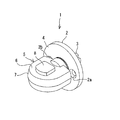
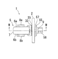
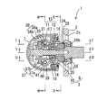
図1は、解錠状態の防犯サムターン1の全体斜視図である。図示しない扉面に対して、ネジ止め可能なサム座2を、サム軸3が後方から前方へ突き抜けて挿通されてなり、サム座2の前面4には摘み5が突設されてなる。 FIG. 1 is an overall perspective view of the crime prevention thumb turn 1 in an unlocked state. A thumb seat 2 which can be screwed is inserted into a door surface (not shown) by penetrating a thumb shaft 3 from the rear side to the front side, and a knob 5 is projectingly provided on a front surface 4 of the thumb seat 2.

摘み5は、サム座2の前面4に対して略垂直な摘み面6を有する中空のケース7を備えてなり、摘み面6は施錠状態において水平とされている。また、本実施の形態において、摘み面6は、サム軸3を挟んで一対の摘み面6a、6bが設けられてなる。 The knob 5 includes a hollow case 7 having a knob surface 6 that is substantially vertical to the front surface 4 of the thumb seat 2, and the knob surface 6 is horizontal in the locked state. In addition, in the present embodiment, the knob surface 6 is provided with a pair of knob surfaces 6a and 6b with the thumb shaft 3 interposed therebetween.

摘み面6a、6bのそれぞれには第一ボタン8a、第二ボタン8bが設けられてなる。以下、第一ボタン8a、及び第二ボタン8bを合わせてボタン8という場合がある。ボタン8は、摘み面6に対して押し込むことができる。 A first button 8a and a second button 8b are provided on each of the grip surfaces 6a and 6b. Hereinafter, the first button 8a and the second button 8b may be collectively referred to as the button 8. The button 8 can be pressed into the knob surface 6.

扉を施解錠しようとする者は、摘み5を軸回転させることによってサム軸3も軸回転させることができ、サム軸3に接続された図示しない扉錠の施錠状態と解錠状態を切り替えることができる。 A person who wants to lock/unlock the door can also rotate the thumb shaft 3 by rotating the knob 5 axially, and can switch between a locked state and an unlocked state of a door lock (not shown) connected to the thumb shaft 3. You can

サム座2は、前面4に設けられたネジ穴2a、2bに挿し入れたネジによって扉面に固定することができる。 The thumb seat 2 can be fixed to the door surface by screws inserted in the screw holes 2a and 2b provided on the front surface 4.

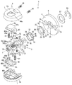
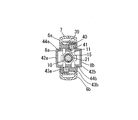
図2は、防犯サムターン1を構成するサム座2、サム軸3、及び摘み5を分解した様子の全体を示す分解斜視図である。 FIG. 2 is an exploded perspective view showing the whole of the thumb seat 2, the thumb shaft 3, and the knob 5 constituting the security thumb turn 1 in an exploded state.

サム軸3は、サム軸基部9の前端に、サム軸基部9よりも径の細いサム軸柱10が螺合された棒体状に構成されてなる。サム軸柱10には、サム軸3の軸方向に沿って前後に摺動可能に設けられてなるスライドピース11及びロックピース12が互いに前後方向に連結されて腕部材13を構成してなる。 The thumb shaft 3 has a rod-like shape in which a thumb shaft column 10 having a diameter smaller than that of the thumb shaft base 9 is screwed into the front end of the thumb shaft base 9. On the thumb shaft column 10, a slide piece 11 and a lock piece 12, which are provided so as to be slidable back and forth along the axial direction of the thumb shaft 3, are connected to each other in the front-back direction to form an arm member 13.

図3には、サム軸3と腕部材13を分解した分解斜視図を示す。 FIG. 3 shows an exploded perspective view in which the thumb shaft 3 and the arm member 13 are disassembled.

スライドピース11は、サム軸3の左右の周面に沿って摺動する棒体状の一対のスライド腕部14、14が、サム軸柱10を挿通可能なスライドピースガイド環15によって連結されて一体に成形されてなる。 In the slide piece 11, a pair of rod-shaped slide arm portions 14 that slide along the left and right peripheral surfaces of the thumb shaft 3 are connected by a slide piece guide ring 15 through which the thumb shaft column 10 can be inserted. It is integrally molded.

ロックピース12は、サム軸3の左右の周面に沿って摺動する棒体状の一対のロック腕部16、16が、サム軸柱10を挿通可能なロックピースガイド環17によって連結されて一体に成形されてなる。 In the lock piece 12, a pair of rod-shaped lock arm portions 16, 16 that slide along the left and right peripheral surfaces of the thumb shaft 3 are connected by a lock piece guide ring 17 through which the thumb shaft column 10 can be inserted. It is integrally molded.

スライドピース11を構成するスライド腕部14の後端部には後端連結爪18が形成され、ロックピース12を構成するロック腕部16,16の前端部には後端連結爪18と互いに係合可能な前端連結爪19が形成されてなり、後端連結爪18と前端連結爪19とが係合されてスライドピース11とロックピース12とが一体に連動する腕部材13を構成してなる。 A rear end connecting pawl 18 is formed on a rear end of the slide arm portion 14 forming the slide piece 11, and a rear end connecting pawl 18 is engaged with each other on front ends of the lock arm portions 16 and 16 forming the lock piece 12. A front end connecting claw 19 that can be fitted is formed, and a rear end connecting claw 18 and a front end connecting claw 19 are engaged with each other to form an arm member 13 in which the slide piece 11 and the lock piece 12 are integrally linked. ..

また、サム軸柱10にはつる巻バネからなるロックバネ21が装着されてなる。ロックバネ21の後端は、ロックピースガイド環17の前面に当接されてなり、ロックバネ21の前端は、サム軸柱10の中間部が拡径して形成されてなる段差面20に当接されてなる。このような構成により、腕部材13には、ロックバネ21によって常に後方へ押し付けられる向きに力が加えられる。 A lock spring 21 made of a spiral spring is mounted on the thumb shaft 10. The rear end of the lock spring 21 is in contact with the front surface of the lock piece guide ring 17, and the front end of the lock spring 21 is in contact with the step surface 20 formed by expanding the intermediate portion of the thumb shaft column 10. It becomes. With such a configuration, a force is applied to the arm member 13 by the lock spring 21 in a direction in which the arm member 13 is always pressed backward.

なお、ロックピースガイド環17は、開口径がロックバネ21の外径よりも小さく形成されてなることによって、サム軸柱10を挿通可能であると共に、ロックバネ21の後端がロックピースガイド環17の前面に当接可能に形成されてなる。 Since the lock piece guide ring 17 has an opening diameter smaller than the outer diameter of the lock spring 21, the thumb shaft column 10 can be inserted, and the rear end of the lock spring 21 has the lock piece guide ring 17. It is formed so that it can contact the front surface.

一方、スライドピースガイド環15は、開口径がロックバネ21の外径よりも大きく形成されてなり、スライドピース11がサム軸3に沿って摺動しても、スライドピースガイド環15がロックバネ21に干渉しない。さらに、スライドピースガイド環15は、サム軸柱10の拡径部分22の外径よりも大きく形成されて、スライドピース11がサム軸3に沿って摺動する場合に、拡径部分22の周面に対面する範囲内で動くことによって、ロックバネ21への干渉をより効果的に回避しつつスライドピース11のガイド機能を発揮する。 On the other hand, the slide piece guide ring 15 is formed so that the opening diameter is larger than the outer diameter of the lock spring 21, and even if the slide piece 11 slides along the thumb shaft 3, the slide piece guide ring 15 does not move to the lock spring 21. Do not interfere. Further, the slide piece guide ring 15 is formed to have a larger diameter than the outer diameter of the enlarged diameter portion 22 of the thumb shaft column 10 and, when the slide piece 11 slides along the thumb shaft 3, the circumference of the enlarged diameter portion 22. By moving within the range of facing the surface, the guide function of the slide piece 11 is exhibited while more effectively avoiding the interference with the lock spring 21.

図3に示すように、サム軸基部9の外周面には、ロック腕部16,16が前後方向に摺動可能に嵌め込み可能な係止溝23,23が形成されてなる。ロック腕部16,16の後端部には、図2に示すように、係止溝23,23に嵌め込まれた状態で、当該係止溝23,23から径方向外方に突出してなるロック用突出部24,24が形成されてなる。 As shown in FIG. 3, locking grooves 23, 23 into which the lock arms 16, 16 are slidably fitted in the front-rear direction are formed on the outer peripheral surface of the thumb shaft base 9. As shown in FIG. 2, the lock arms 16, 16 are locked in the locking grooves 23, 23 in a state of being fitted in the locking grooves 23, 23 and projecting radially outward from the locking grooves 23, 23. The projecting portions 24, 24 are formed.

図2に示すように、サム座2の中央にはサム座軸受25を嵌め込んで固定することができる固定凹部26と、固定凹部26の中央部を貫通してサム軸3を挿通可能に形成された挿通孔27とが形成されてなる。 As shown in FIG. 2, a fixing recess 26 into which a thumb seat bearing 25 can be fitted and fixed in the center of the thumb seat 2, and a thumb shaft 3 that can be inserted through the central portion of the fixing recess 26. And the inserted insertion hole 27 is formed.

サム座軸受25は、図4に示すように、サム軸3を貫通可能に形成されてなる貫通孔28、及びロック用突出部24,24を前方向から嵌め込み可能に形成されたロック溝29,29を有する円環状に形成された部材であり、前端面から外周方向に延出してなる鍔30が形成されてなる。 As shown in FIG. 4, the thumb seat bearing 25 has a through hole 28 formed so as to penetrate the thumb shaft 3 and a lock groove 29 formed so that the locking projections 24, 24 can be fitted from the front side. It is a member formed in an annular shape having 29, and is formed with a collar 30 extending from the front end face in the outer peripheral direction.

固定凹部26の内側面には、左右に対面する位置に、回転防止溝31,31が形成されてなり、サム座軸受25の左右の外周面から突設されてなる回転防止突部32,32を嵌め込むことによって、固定凹部26に嵌め込まれたサム座軸受25が回動しないように固定することができる。 Anti-rotation protrusions 32, 32 are formed on the inner side surface of the fixed recessed portion 26, which are formed with anti-rotation grooves 31, 31 at positions facing left and right and project from the left and right outer peripheral surfaces of the thumb seat bearing 25. The thumb seat bearing 25 fitted in the fixed recess 26 can be fixed so as not to rotate by fitting.

図2に示すように、ロック溝29,29は、ロック腕部16,16と、それぞれ前後方向に対向する位置に設けられてなり、サム座軸受25の前面から内周面にかけて切り欠き構造に形成されてなる。 As shown in FIG. 2, the lock grooves 29, 29 are provided at positions facing the lock arm portions 16, 16 in the front-rear direction, respectively, and have a notch structure from the front surface to the inner peripheral surface of the thumb seat bearing 25. It is formed.

サム座軸受25の前面と対面する位置には、サムピースガイド33が設置されている。サムピースガイド33の後端部は、環状の円盤34が形成されてなる。円盤34の前面にはサム軸基部9の周面に沿って形成された円弧状板体のガイド板35が上下に分割して前方に突設されてなる。ガイド板35が分割されてなる左右端部は、それぞれ径方向外方に屈曲された屈曲部からなるロックピースガイド36に形成されてなる。ロックピースガイド36は、前後方向に摺動するロックピース12の軸回転を抑制する機能を備える。 A thumb piece guide 33 is installed at a position facing the front surface of the thumb seat bearing 25. An annular disk 34 is formed at the rear end of the thumb piece guide 33. On the front surface of the disk 34, a guide plate 35, which is an arc-shaped plate body formed along the peripheral surface of the thumb shaft base 9, is vertically divided and protrudes forward. The left and right ends of the guide plate 35 that are divided are formed into lock piece guides 36 that are bent portions that are bent outward in the radial direction. The lock piece guide 36 has a function of suppressing axial rotation of the lock piece 12 sliding in the front-rear direction.

スライドピース11のスライド腕部14,14の外側面には、外方に突設されてなる摺動突部37,38が設けられてなる。 On the outer side surfaces of the slide arm portions 14, 14 of the slide piece 11, there are provided sliding protrusion portions 37, 38 which are protruded outward.

図2において、サム座2の前面に向かって右手方向に突設されてなる摺動突部37は、上方から下方に向かうに従って前方から後方に傾斜してなる傾斜板37a、及び傾斜板37aの外側面から下方に屈曲されてなる係合ガイド37bによって構成されてなる。 In FIG. 2, the sliding protrusion 37, which is provided so as to protrude in the right-hand direction toward the front surface of the thumb seat 2, is an inclined plate 37a inclined from the front to the rear as it goes downward from above, and the inclined plate 37a. The engaging guide 37b is bent downward from the outer side surface.

また図2において、サム座2の前面に向かって左手方向に突設されてなる摺動突部38は、上方から下方に向かうに従って後方から前方に傾斜してなる傾斜板38a、及び傾斜板38aの外側面から上方に屈曲されてなる係合ガイド38bによって構成されてなる。 Further, in FIG. 2, the sliding projection 38, which is provided so as to project in the left-hand direction toward the front surface of the thumb seat 2, has a slanted plate 38a and a slanted plate 38a that are slanted from the rear to the front as going from the upper side to the lower side. Of the engaging guide 38b which is bent upward from the outer side surface of the.

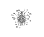
図2に示すように、第一ボタン8a及び第二ボタン8bは、サム軸柱10の軸中心Yを対称軸として、サム軸柱10の上側と下側とに配置されてなる。第一ボタン8a及び第二ボタン8bには、それぞれバネ取付柱39,39、及びバネ受け40,40を備えてなり、互いのバネ取付柱とバネ受けとを向かい合わせとなる位置において、バネ取付柱にバネ41,41を装着させると共に、バネ受け40,40に挿し込まれてなる。バネ41,41は、ボタン8を押し込む力に対して抵抗する向きに力を加え、押し込まれたボタン8から押し込む力が解放されると元の位置へ押し戻す。 As shown in FIG. 2, the first button 8a and the second button 8b are arranged on the upper side and the lower side of the thumb shaft column 10 with the axis Y of the thumb shaft column 10 as the axis of symmetry. The first button 8a and the second button 8b are provided with spring mounting columns 39, 39 and spring receivers 40, 40, respectively, and the spring mounting columns and the spring bearings face each other at a position where the springs are mounted. The columns are provided with springs 41, 41, and are inserted into the spring receivers 40, 40. The springs 41, 41 apply a force in a direction that resists the pushing force of the button 8, and when the pushing force of the pushed button 8 is released, the springs 41, 41 return to the original position.

ボタン8は、図2に示すように、指で直接触れながら軸中心Yに向かって押し込む押込み凸部42(42a、42b)と、押込み凸部42の軸中心Y側の端部周面から延出してなる止め板43(43a、43b)によって構成されてなる。 As shown in FIG. 2, the button 8 extends from the pushing convex portion 42 (42a, 42b) that is pushed toward the axial center Y while directly touching it with a finger and from the peripheral surface of the pushing convex portion 42 on the axial center Y side. It is composed of the stopper plates 43 (43a, 43b) that are extended.

図2に示すように、ケース7の摘み面6には凸部42の上部が外部に突出可能なボタン穴44(44a、44b)が形成されてなる。止め板43は、それぞれのボタン穴44よりも大きな外縁形状を備えている。これにより、押し込む力が解放されたボタン8を、止め板43が摘み5の内側面に当接してバネ41,41の力を止めることで、図1に示すように、ボタン穴44から一定の高さ突出する位置に留めることができる。 As shown in FIG. 2, the knob surface 6 of the case 7 is formed with button holes 44 (44a, 44b) that allow the upper portion of the convex portion 42 to project to the outside. The stop plate 43 has an outer edge shape larger than each button hole 44. As a result, the stopper plate 43 abuts the inner surface of the knob 5 to stop the force of the springs 41, 41 from the button 8 in which the pushing force has been released, and as shown in FIG. It can be kept in a position where it protrudes.

さらに、止め板43から軸中心Y側に対して垂直に延出してなる側壁45(45a、45b)には、切り欠き46(46a、46b)が形成されてなる。切り欠き46は、前後に幅狭の直線状の切り欠きであり、側壁45の軸中心Y側の端縁に形成された解放端47(47a,47b)から、それぞれのボタン8が装着された摘み5の摘み面6に向かうに従って前方向、若しくは後方向に斜めに切り込んだ形状に形成されてなる。 Furthermore, notches 46 (46a, 46b) are formed on the side walls 45 (45a, 45b) extending perpendicularly to the axial center Y side from the stopper plate 43. The notch 46 is a linear notch having a narrow width in the front and rear, and each button 8 is attached from the release end 47 (47a, 47b) formed at the edge of the side wall 45 on the axial center Y side. It is formed in a shape that is obliquely cut forward or backward as it goes toward the picking surface 6 of the knob 5.

本実施の形態においては、図2に示すように切り欠き46aは、サム座2の正面に対して上側に配置された第一ボタン8aの右側から下方向に延出してなる側壁45aに設けられてなる。切り欠き46aは、解放端47aから摘み面6aに向かうに従って前方に向かって斜めに切り込んだ形状に形成されてなる。 In the present embodiment, as shown in FIG. 2, the notch 46a is provided in the side wall 45a extending downward from the right side of the first button 8a arranged above the front of the thumb seat 2. It becomes. The notch 46a is formed in a shape that is obliquely cut forward toward the picking surface 6a from the open end 47a.

一方、図2に示すように切り欠き46bは、サム座2の正面に対して下側に配置された第二ボタン8bの左側から上方向に延出してなる側壁45bに設けられてなる。切り欠き46bは、解放端47bから摘み面6bに向かうに従って前方に向かって斜めに切り込んだ形状に形成されてなる。 On the other hand, as shown in FIG. 2, the notch 46b is provided in the side wall 45b extending upward from the left side of the second button 8b arranged on the lower side with respect to the front surface of the thumb seat 2. The notch 46b is formed in a shape that is obliquely cut forward toward the grip surface 6b from the open end 47b.

摺動突部37は、切り欠き46aと共に、第一ボタン8aが押し込まれると傾斜板37aが切り欠き46aの解放端47aから奥端48aへ向かって摺動する係合部49aを構成する。一方、摺動突部38は、切り欠き46bと共に、第二ボタン8bが押し込まれると傾斜板38aが切り欠き46bの解放端47bから奥端48bに向かって摺動する係合部49bを構成する。 The sliding protrusion 37 constitutes, together with the cutout 46a, an engaging portion 49a with which the inclined plate 37a slides from the open end 47a of the cutout 46a toward the rear end 48a when the first button 8a is pressed. On the other hand, the sliding protrusion 38 constitutes, together with the cutout 46b, an engaging portion 49b in which the inclined plate 38a slides from the open end 47b of the cutout 46b toward the rear end 48b when the second button 8b is pressed. ..

ケース7は、上下に分割されてなり、サム軸3の前端部、腕部材13、及びボタン8を内部に挟み込んで摘み5を構成する。ケース7の後端は解放されてなり、サムピースガイド33のガイド板35を嵌め込むことができる。これにより、ロックピース12のロック腕部16,16の後端部を後方に向かって出没させることができる。なお、摘み5を形成したケース7はネジ50、50によって固定される。 The case 7 is divided into upper and lower parts, and the front end of the thumb shaft 3, the arm member 13, and the button 8 are sandwiched inside to form the knob 5. The rear end of the case 7 is released so that the guide plate 35 of the thumb piece guide 33 can be fitted therein. Thereby, the rear ends of the lock arms 16 and 16 of the lock piece 12 can be projected and retracted rearward. The case 7 having the knob 5 is fixed by screws 50, 50.

また、サム軸基部9の上下面には円筒状のバネ穴51、51が形成されてなり、バネ穴51には小バネ52、52と、小バネ52の外側端に設置されたクリックボール53、53とが収容されてなる。ケース7の内面には窪み54、54が形成されてなり、クリックボール53の外表面の一部を、小バネ52に押し付けられながらはめこむことができる。操作者がシリンダー側からサム軸3を軸回転させて施錠した際に、クリックボール53が窪み54はまりこんだ時のクリック感が、操作者の指に伝わることで、施錠位置を確認することができる。 Further, cylindrical spring holes 51, 51 are formed in the upper and lower surfaces of the thumb shaft base 9, and small springs 52, 52 are formed in the spring hole 51, and a click ball 53 installed at an outer end of the small spring 52. , 53 are accommodated. The case 7 is formed with depressions 54, 54, and a part of the outer surface of the click ball 53 can be fitted while being pressed against the small spring 52. When the operator locks the thumb shaft 3 by rotating the thumb shaft 3 from the cylinder side, the click feeling when the click ball 53 fits into the recess 54 is transmitted to the operator's finger, whereby the locked position can be confirmed. ..

図2に示すように、サム軸基部9の中央部周面には止め輪55を嵌め込む止め輪溝56が形成されてなる。サム座2の挿通孔27を挿通されたサム軸3に、サム座2の後面からワッシャー57及び止め輪55を嵌め込んで、サム軸3がサム座2から抜け落ちることを防止する。 As shown in FIG. 2, a retaining ring groove 56 into which a retaining ring 55 is fitted is formed on the peripheral surface of the central portion of the thumb shaft base 9. The washer 57 and the retaining ring 55 are fitted from the rear surface of the thumb seat 2 to the thumb shaft 3 that has been inserted through the through hole 27 of the thumb seat 2 to prevent the thumb shaft 3 from falling off the thumb seat 2.

また、サム軸基部9の後端部の周面には、四方から軸中心に対して直角の面からなる鍵溝58が後端に向かって形成されてなり、後端面が十字型に形成されてなる。図示しない扉錠のハブに、当該鍵溝58が挿し入れられてサム軸3を軸回転させると、サム軸3の回転力によって扉錠の施解錠を行うことができる。なお、サム軸3は摘み5を軸回転させる場合の他、扉を挟んだ反対側に設けられたシリンダーに挿し込んだ鍵等によっても軸回転させることができる。 Further, on the peripheral surface of the rear end of the thumb shaft base 9, there are formed key grooves 58 each of which is a surface perpendicular to the shaft center from four sides, and the rear end is formed in a cross shape. It becomes. When the keyway 58 is inserted into a door lock hub (not shown) and the thumb shaft 3 is rotated, the door lock can be locked and unlocked by the rotational force of the thumb shaft 3. The thumb shaft 3 can be rotated not only by rotating the knob 5 but also by a key or the like inserted in a cylinder provided on the opposite side of the door.

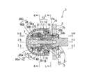
図7〜図13に示すように、ロック用突出部24,24がロック溝29,29に嵌め込まれ、第一ボタン8aと第二ボタン8bとが解放された状態においては、ロックバネ21がロックピース12を後方へ押し付けている。この場合、第一ボタン8a及び第二ボタン8bを押し込まずに摘み5を軸回転させようとしてもロック溝29,29に嵌め込まれたロック用突出部24,24の軸回転がサム座軸受25によって制限される。そのため、サム軸3を軸回転させることができず、施錠状態の扉錠を解錠させることはできない。 As shown in FIGS . 7 to 13 , when the locking protrusions 24, 24 are fitted into the lock grooves 29, 29, and the first button 8a and the second button 8b are released, the lock spring 21 locks the lock piece. 12 is pushed backwards. In this case, even if an attempt is made to axially rotate the knob 5 without pushing in the first button 8a and the second button 8b, the axial rotation of the locking projections 24, 24 fitted in the lock grooves 29, 29 is caused by the thumb seat bearing 25. Limited. Therefore, the thumb shaft 3 cannot be rotated and the door lock in the locked state cannot be unlocked.

また、本実施の形態においては、第一ボタン8a及び第二ボタン8bの両方を互いに突き合う方向に押さなければ腕部材13を前方に移動させて、ロック溝29,29からロック用突出部24,24を解放することができない。一方の摘み面6にのみボタン8が設けられてなる場合には、ボタン8を押し下げるか、押し上げるかのいずれかの動作によってのみロック用突出部24,24を解放することができる。 In addition, in the present embodiment, unless both the first button 8a and the second button 8b are pressed in the direction of butting each other, the arm member 13 is moved forward, and the locking projections 24 are moved from the lock grooves 29, 29. , 24 cannot be released. When the button 8 is provided only on one of the knob surfaces 6, the locking projections 24, 24 can be released only by pushing down or pushing up the button 8.

しかし本実施の形態における構成によれば、ロック用突出部24,24を解放するために、一方の摘み面6にのみボタン8が設けられてなる場合よりも複雑な操作が必要となるため、サムターン回しがより困難で、防犯性の高い防犯サムターンを実現することができる。 However, according to the configuration of the present embodiment, in order to release the locking protrusions 24, 24, a more complicated operation is required than in the case where the button 8 is provided only on the one gripping surface 6, It is more difficult to turn the thumb turn, and it is possible to realize a crime prevention thumb turn with high security.

扉錠を解錠しようとする者が、第一ボタン8aと第二ボタン8bとを同時に押し込むと、図14〜図20に示すように、摺動突部37,38がそれぞれ切り欠き46a,46bに沿って解放端47a,47bから奥端48a,48bに向かって摺動し、係合部49a,49bが深く噛み合うことにより、腕部材13を前方へ移動させる。これにより、図5に示すように、ロック用突出部24,24を、ロック溝29,29から前方へ脱離させることができる。従って、第一ボタン8aと第二ボタン8bとを押し込むことにより、サム軸3の軸回転への制限を解除することができる。 When a person who tries to unlock the door lock pushes in the first button 8a and the second button 8b at the same time, as shown in FIGS. 14 to 20 , the sliding protrusions 37 and 38 have notches 46a and 46b, respectively. Along with the sliding ends 47a, 47b toward the rear ends 48a, 48b, and the engaging portions 49a, 49b deeply mesh with each other, thereby moving the arm member 13 forward. Thereby, as shown in FIG. 5, the locking protrusions 24, 24 can be detached forward from the lock grooves 29, 29. Therefore, by pressing the first button 8a and the second button 8b, the restriction on the axial rotation of the thumb shaft 3 can be released.

また、第一ボタン8aと第二ボタン8bとを押し込んだ状態であっても、ロックピース12のロック腕部16,16は、係止溝23,23には係っているため、摘み5を軸回転させる力をサム軸3で伝達することができる。従って、第一ボタン8aと第二ボタン8bとを押し込んだ状態で摘み5を軸回転させるとサム軸3を軸回転させることができ、施錠されていた扉錠を解錠させることができる。 Further, even when the first button 8a and the second button 8b are pushed in, the lock arms 16 of the lock piece 12 are engaged with the locking grooves 23, 23, so that the knob 5 can be removed. The force for rotating the shaft can be transmitted by the thumb shaft 3. Therefore, when the knob 5 is axially rotated while the first button 8a and the second button 8b are pushed, the thumb shaft 3 can be axially rotated, and the locked door lock can be unlocked.

次に、サム軸3が直接軸回転される場合の防犯サムターン1の動作について説明する。 Next, the operation of the crime prevention thumb turn 1 when the thumb shaft 3 is directly rotated will be described.

サム軸3が直接軸回転される場合の例として、サム座2が取り付けられてなる扉面とは反対側の扉面に設けられたシリンダーとサム軸3とが連結されてなる場合に、前記シリンダーに挿し込んだ鍵を軸回転させることによってサム軸3が軸回転される場合等が挙げられる。 As an example of the case where the thumb shaft 3 is directly rotated, when the cylinder provided on the door surface opposite to the door surface to which the thumb seat 2 is attached and the thumb shaft 3 are connected, For example, the thumb shaft 3 may be rotated by rotating the key inserted in the cylinder.

図22に示すように、係止溝23,23の後端内面59(59a,59b)にはカム面60(60a,60b)が形成されてなる。本実施の形態において、カム面60aは、後端内面59aの下側隅部分に形成され、カム面60bは、後端内面59bの上側隅部分に形成されてなる。カム面60は、後端内面59の中央平坦部よりも前方に傾斜する傾斜面に形成されてなる。サム軸3を解錠する方向に軸回転させると、図6、及び図21〜図27に示すように、ロック用突出部24,24が前方に押し出されてロックピース12をロック溝29,29から離脱させる。さらに鍵を回し続けると、サム軸3の軸回転の制限を超えて軸回転させることができ、施錠されていた扉錠を解錠させることができる。 As shown in FIG. 22 , cam surfaces 60 (60a, 60b) are formed on the rear end inner surfaces 59 (59a, 59b) of the locking grooves 23 , 23 . In the present embodiment, the cam surface 60a is formed at the lower corner portion of the rear end inner surface 59a, and the cam surface 60b is formed at the upper corner portion of the rear end inner surface 59b. The cam surface 60 is formed as an inclined surface that is inclined forward of the central flat portion of the rear end inner surface 59. When the thumb shaft 3 is rotated in the unlocking direction, as shown in FIG. 6 and FIGS. Disengage from. When the key is further turned, the thumb shaft 3 can be rotated beyond the limit of the shaft rotation, and the door lock that has been locked can be unlocked.

次に、本実施の形態において、第一ボタン8a、若しくは第二ボタン8bのいずれかのみを押し込んだ場合の防犯機構について説明する。例として、第一ボタン8aのみを押し込もうとした場合の動作について、図に基づいて説明する。 Next, in the present embodiment, the crime prevention mechanism when only either the first button 8a or the second button 8b is pushed will be described. As an example, an operation when only the first button 8a is pressed will be described with reference to the drawings.

図28〜図34に示すように、第一ボタン8aのみを押し込もうとした場合、傾斜板37aの前面が切り欠き46bの解放端47bに当接して切り欠き46b内への進入が阻害される。このため、第一ボタン8aのみを押し込もうとしても腕部材13を前方へ摺動させることができず、ロック用突出部24を、ロック溝29から脱離させることができない。従って、第一ボタン8aのみを押し込もうとしてもサム軸3の軸回転の制限を解除することができない。なお、この場合、第一ボタン8aは、ほとんどボタン穴44aには沈み込まない。これは、第二ボタン8bのみを押し込もうとした場合であっても同様である。 As shown in FIGS. 28 to 34, when only the first button 8a is pressed, the front surface of the inclined plate 37a abuts on the open end 47b of the cutout 46b and the entry into the cutout 46b is obstructed. It Therefore, even if only the first button 8a is pushed in, the arm member 13 cannot be slid forward, and the locking protrusion 24 cannot be detached from the lock groove 29. Therefore, even if only the first button 8a is pushed, the limitation of the axial rotation of the thumb shaft 3 cannot be released. In this case, the first button 8a hardly sinks into the button hole 44a. This is the same even when only the second button 8b is pushed.

このような一方のボタン8のみを押し込もうとした場合にサム軸3の軸回転の制限を解除できないようにするためには、ボタン8がサム軸3を挟んで設けられてなる一対となる第一ボタン8a及び第二ボタン8bとから構成されてなることが好ましい。さらに、第一ボタン8a及び第二ボタン8bには、それぞれ摺動突部37,38及び切り欠き46a,46bに相当する構造が設けられ、それぞれのボタン8に設けられた摺動突部37,38及び切り欠き46a,46bが互いに噛み合う係合部49を構成することが好ましい。一方のボタン8には摺動突部のみが設けられ、他方のボタン8には切り欠きのみが設けられる構造とした場合には、一方のボタン8のみを押し込もうとした場合にも容易に摺動突部が切り欠き内へ進入し、サム軸3の軸回転の制限を解除できないようにする効果が十分得られない可能性があるからである。 In order to prevent the restriction of the axial rotation of the thumb shaft 3 from being released when only one of the buttons 8 is pushed in, the buttons 8 are provided as a pair with the thumb shaft 3 sandwiched therebetween. It is preferably composed of a first button 8a and a second button 8b. Further, the first button 8a and the second button 8b are provided with structures corresponding to the sliding protrusions 37, 38 and the notches 46a, 46b, respectively, and the sliding protrusions 37, 38 provided on the respective buttons 8 are provided. 38 and the notches 46a and 46b preferably form an engaging portion 49 that meshes with each other. When one button 8 is provided with only the sliding protrusion and the other button 8 is provided with only the notch, it is easy to push only one button 8 This is because there is a possibility that the sliding protrusion may enter the notch and the effect of preventing the restriction of the axial rotation of the thumb shaft 3 from being released cannot be sufficiently obtained.

特に、このような一方のボタン8のみを押し込もうとしてもサム軸3の軸回転の制限が解除できないようにするために、傾斜板37a,38aの前端に垂直面37c,38cが形成されてなることが好ましい。傾斜板37a,38aの前端面に垂直面37c,38cを設けることで、一方のボタン8を押し込もうとした場合に、傾斜板37a,38aに対応する解放端47a,47bに前記垂直面37c,38cが当接することによって、前記垂直面37c,38cに対して直角方向となる前方への腕部材13の移動を効果的に止めることができるからである。 In particular, vertical surfaces 37c, 38c are formed at the front ends of the inclined plates 37a, 38a in order to prevent the restriction of the axial rotation of the thumb shaft 3 from being released even if only one of the buttons 8 is pushed in. It is preferable that By providing the vertical surfaces 37c, 38c on the front end surfaces of the inclined plates 37a, 38a, when one button 8 is to be pushed, the vertical surfaces 37c are formed on the release ends 47a, 47b corresponding to the inclined plates 37a, 38a. , 38c are in contact with each other, it is possible to effectively stop the movement of the arm member 13 to the front, which is a direction perpendicular to the vertical surfaces 37c, 38c.

1 防犯サムターン
2 サム座
3 サム軸
5 摘み
7 ケース
8 ボタン
11 スライドピース
12 ロックピース
13 腕部材
21 ロックバネ
23 係止溝
24 ロック用突出部
25 サム座軸受
27 挿通孔
28 貫通孔
29 ロック溝
37 摺動突部
38 摺動突部
45 側壁
46 切り欠き
47 解放端
48 奥端
49 係合部
59 後端内面
60 カム面
1 Security Thumb Turn 2 Thumb Seat 3 Thumb Shaft 5 Pick 7 Case 8 Button 11 Slide Piece 12 Lock Piece 13 Arm Member 21 Lock Spring 23 Locking Groove 24 Lock Protrusion 25 Thumb Seat Bearing 27 Insertion Hole 28 Through Hole 29 Lock Groove 37 Sliding Moving protrusion 38 Sliding protrusion 45 Side wall 46 Notch 47 Release end 48 Inner end 49 Engaging portion 59 Rear end inner surface 60 Cam surface

Claims (5)

サム軸が挿通されてなる挿通孔を有してなるサム座と、
前記サム座の前面から前方に突設されると共に前記サム座の前面に対して略垂直な摘み面を有し、前記サム軸と共に軸回転可能に取付けられてなる摘みと、
前記摘み面に設けられてなるボタンと、
前記ボタンよりもサム軸の軸中心側において前記サム軸に沿って後方に延設される腕部材と、
前記腕部材の後端部を構成し、前記サム軸の外周面に設けられてなる係止溝に前後方向に摺動可能に嵌め込まれてなると共に、前記係止溝から径方向外方に突出してなるロック用突出部を有するロックピースと、
前記サム軸が貫通されてなる貫通孔、及び前記ロック用突出部を前方向から嵌め込み可能に形成されたロック溝を有し、前記サム座に固定されてなるサム座軸受と、
前後方向に斜めに切り込まれた切り欠き、及び当該切り欠きに入出可能な摺動突部によって構成されてなると共に、前記摘みの内部において前記ボタン及び前記腕部材を係合可能とする係合部と、を備え、
前記ボタンを押し込むと、前記係合部は、前記摺動突部を前記切り欠きの解放端から奥端へ向かって摺動させながら前記腕部材を前方へ移動させると共に、前記ロック用突出部を前記ロック溝から脱離させる
ことを特徴とする防犯サムターン。
A thumb seat having an insertion hole formed by inserting the thumb shaft,
A knob that protrudes forward from the front surface of the thumb seat and has a knob surface that is substantially vertical to the front surface of the thumb seat, and is attached so as to be axially rotatable with the thumb shaft.
A button provided on the knob surface,
An arm member extending rearward along the thumb shaft on the axial center side of the thumb shaft with respect to the button,
The arm member constitutes a rear end portion of the arm member, is fitted in a locking groove formed on the outer peripheral surface of the thumb shaft so as to be slidable in the front-rear direction, and protrudes radially outward from the locking groove. A lock piece having a locking protrusion formed by
A through hole formed through the thumb shaft, and a thumb seat bearing having a lock groove formed so that the locking protrusion can be fitted from the front side, and fixed to the thumb seat.
Engagement that includes a notch cut obliquely in the front-rear direction and a sliding protrusion that can be inserted into and removed from the notch, and that allows the button and the arm member to engage with each other inside the knob. And a section,
When the button is pushed in, the engaging portion moves the arm member forward while sliding the sliding protrusion from the open end of the notch toward the rear end, and at the same time, causes the locking protrusion to move. A crime prevention thumb turn characterized by being detached from the lock groove.
前記係止溝の後端内面が、前記サム軸を解錠する方向に軸回転させると、前記ロック用突出部を前方に押し可能なカム面に形成され、
前記サム軸を解錠する方向に軸回転させると、前記カム面が前記ロック用突出部を前方に押し出して前記ロック溝から離脱させる
ことを特徴とする請求項1に記載の防犯サムターン。
The inner surface of the rear end of the locking groove is formed into a cam surface capable of pushing the locking protrusion forward when the thumb shaft is rotated in the unlocking direction.
The security thumb turn according to claim 1, wherein when the thumb shaft is rotated in a direction of unlocking, the cam surface pushes the locking protrusion forward and disengages it from the lock groove.
前記切り欠きは、前記ボタンのサム軸の軸中心側の端面に前記解放端を有して前記摘み面に向かって形成されてなる
ことを特徴とする請求項1又は請求項2に記載の防犯サムターン。
The crime prevention according to claim 1 or 2, wherein the notch has the release end at an end surface of a thumb shaft of the button on the axial center side and is formed toward the knob surface. Sam Turn.
前記ボタンが、前記摘みにおいて前記サム軸を挟んで設けられてなる一対の前記摘み面のそれぞれに設けられてなる第一ボタン及び第二ボタンによって構成されてなる
ことを特徴とする請求項1〜3のいずれかに記載の防犯サムターン。
The button is configured by a first button and a second button provided on each of a pair of the knob surfaces that are provided with the thumb shaft sandwiched in the knob. The security thumb turn according to any one of 3 above.
前記切り欠きが、前記第一ボタン及び前記第二ボタンのそれぞれに設けられてなる
ことを特徴とする請求項4に記載の防犯サムターン。
The crime prevention thumb turn according to claim 4, wherein the notch is provided in each of the first button and the second button.
JP2017247899A 2017-12-25 2017-12-25 Security thumb turn Active JP6734523B2 (en)

Priority Applications (1)

Application Number Priority Date Filing Date Title
JP2017247899A JP6734523B2 (en) 2017-12-25 2017-12-25 Security thumb turn

Applications Claiming Priority (1)

Application Number Priority Date Filing Date Title
JP2017247899A JP6734523B2 (en) 2017-12-25 2017-12-25 Security thumb turn

Publications (2)

Publication Number Publication Date
JP2019112850A JP2019112850A (en) 2019-07-11
JP6734523B2 true JP6734523B2 (en) 2020-08-05

Family

ID=67221334

Family Applications (1)

Application Number Title Priority Date Filing Date
JP2017247899A Active JP6734523B2 (en) 2017-12-25 2017-12-25 Security thumb turn

Country Status (1)

Country Link
JP (1) JP6734523B2 (en)

Also Published As

Publication number Publication date
JP2019112850A (en) 2019-07-11

Similar Documents

Publication Publication Date Title
CA2529547C (en) Door lock assembly having a press button in an inner handle
US11220837B2 (en) Privacy lock mechanism
US20090301147A1 (en) Compound lock
CA2767508C (en) Exchangeable cylinder lock assembly
CA2779940A1 (en) Push-button type cylinder lock assembly
US3196644A (en) Spindle device for releasably retaining a locking mechanism assembly
JP6734523B2 (en) Security thumb turn
JP2010242389A (en) Cylinder lock
JP4478620B2 (en) Thumb turn unit
JP4550637B2 (en) Thumb turn device
JP3050628B2 (en) Cylinder lock
JP2554582Y2 (en) Cylinder lock
JP4702682B2 (en) Thumb turn device
JP3090356B2 (en) Cylinder lock
KR200482418Y1 (en) dial-key typed window locking Device
KR102332677B1 (en) Locking device to prevent rotation of dialing in opening states
JP5114467B2 (en) Thumb turn unit
JP4698369B2 (en) Latch lock
JP3380611B2 (en) Cylinder lock
JP2980251B2 (en) Cylinder lock
JP3165641U (en) Dial lock
TWI596269B (en) A dial lock
US20130118218A1 (en) Lock assembly having outer and inner lock units
JP4154192B2 (en) Sliding door lock
JP3105519U (en) Thumb turn with knob lock

Legal Events

Date Code Title Description
A621 Written request for application examination

Free format text: JAPANESE INTERMEDIATE CODE: A621

Effective date: 20190730

A977 Report on retrieval

Free format text: JAPANESE INTERMEDIATE CODE: A971007

Effective date: 20200421

TRDD Decision of grant or rejection written
A01 Written decision to grant a patent or to grant a registration (utility model)

Free format text: JAPANESE INTERMEDIATE CODE: A01

Effective date: 20200526

A61 First payment of annual fees (during grant procedure)

Free format text: JAPANESE INTERMEDIATE CODE: A61

Effective date: 20200618

R150 Certificate of patent or registration of utility model

Ref document number: 6734523

Country of ref document: JP

Free format text: JAPANESE INTERMEDIATE CODE: R150

R250 Receipt of annual fees

Free format text: JAPANESE INTERMEDIATE CODE: R250