JP6734368B2 - Dosimeter container and dosimeter - Google Patents
Dosimeter container and dosimeter Download PDFInfo
- Publication number
- JP6734368B2 JP6734368B2 JP2018517656A JP2018517656A JP6734368B2 JP 6734368 B2 JP6734368 B2 JP 6734368B2 JP 2018517656 A JP2018517656 A JP 2018517656A JP 2018517656 A JP2018517656 A JP 2018517656A JP 6734368 B2 JP6734368 B2 JP 6734368B2
- Authority
- JP
- Japan
- Prior art keywords
- dosimeter container
- dosimeter
- lif
- shielding
- radiation
- Prior art date
- Legal status (The legal status is an assumption and is not a legal conclusion. Google has not performed a legal analysis and makes no representation as to the accuracy of the status listed.)
- Active
Links
- 230000005855 radiation Effects 0.000 claims description 84
- 238000003860 storage Methods 0.000 claims description 54
- 239000000470 constituent Substances 0.000 claims description 20
- 238000005259 measurement Methods 0.000 claims description 18
- 230000004308 accommodation Effects 0.000 claims description 2
- PQXKHYXIUOZZFA-UHFFFAOYSA-M lithium fluoride Chemical compound [Li+].[F-] PQXKHYXIUOZZFA-UHFFFAOYSA-M 0.000 description 123
- 239000011521 glass Substances 0.000 description 14
- 239000000463 material Substances 0.000 description 14
- 238000000034 method Methods 0.000 description 14
- 238000010586 diagram Methods 0.000 description 9
- 238000010304 firing Methods 0.000 description 9
- 239000000203 mixture Substances 0.000 description 7
- ZOXJGFHDIHLPTG-UHFFFAOYSA-N Boron Chemical compound [B] ZOXJGFHDIHLPTG-UHFFFAOYSA-N 0.000 description 6
- 229910052796 boron Inorganic materials 0.000 description 6
- 238000002560 therapeutic procedure Methods 0.000 description 6
- 206010028980 Neoplasm Diseases 0.000 description 5
- 201000011510 cancer Diseases 0.000 description 5
- 230000000694 effects Effects 0.000 description 5
- 238000004519 manufacturing process Methods 0.000 description 5
- 238000011156 evaluation Methods 0.000 description 4
- 238000000465 moulding Methods 0.000 description 4
- 229910004261 CaF 2 Inorganic materials 0.000 description 3
- 229910000978 Pb alloy Inorganic materials 0.000 description 3
- 150000001639 boron compounds Chemical class 0.000 description 3
- 238000001816 cooling Methods 0.000 description 3
- 239000013078 crystal Substances 0.000 description 3
- 238000005520 cutting process Methods 0.000 description 3
- 230000005251 gamma ray Effects 0.000 description 3
- 238000012545 processing Methods 0.000 description 3
- 229920005989 resin Polymers 0.000 description 3
- 239000011347 resin Substances 0.000 description 3
- 238000005245 sintering Methods 0.000 description 3
- 230000008961 swelling Effects 0.000 description 3
- 239000002775 capsule Substances 0.000 description 2
- 238000001514 detection method Methods 0.000 description 2
- 239000012535 impurity Substances 0.000 description 2
- 239000000155 melt Substances 0.000 description 2
- 239000000843 powder Substances 0.000 description 2
- 230000002250 progressing effect Effects 0.000 description 2
- 239000002994 raw material Substances 0.000 description 2
- 229920005992 thermoplastic resin Polymers 0.000 description 2
- WHXSMMKQMYFTQS-UHFFFAOYSA-N Lithium Chemical compound [Li] WHXSMMKQMYFTQS-UHFFFAOYSA-N 0.000 description 1
- 235000021355 Stearic acid Nutrition 0.000 description 1
- 230000004913 activation Effects 0.000 description 1
- 230000005260 alpha ray Effects 0.000 description 1
- 229910052790 beryllium Inorganic materials 0.000 description 1
- ATBAMAFKBVZNFJ-UHFFFAOYSA-N beryllium atom Chemical compound [Be] ATBAMAFKBVZNFJ-UHFFFAOYSA-N 0.000 description 1
- 229910002056 binary alloy Inorganic materials 0.000 description 1
- 229920002678 cellulose Polymers 0.000 description 1
- 239000001913 cellulose Substances 0.000 description 1
- 239000002131 composite material Substances 0.000 description 1
- 238000012937 correction Methods 0.000 description 1
- 230000007547 defect Effects 0.000 description 1
- IMBKASBLAKCLEM-UHFFFAOYSA-L ferrous ammonium sulfate (anhydrous) Chemical compound [NH4+].[NH4+].[Fe+2].[O-]S([O-])(=O)=O.[O-]S([O-])(=O)=O IMBKASBLAKCLEM-UHFFFAOYSA-L 0.000 description 1
- 235000003891 ferrous sulphate Nutrition 0.000 description 1
- 239000011790 ferrous sulphate Substances 0.000 description 1
- 150000002484 inorganic compounds Chemical class 0.000 description 1
- 229910010272 inorganic material Inorganic materials 0.000 description 1
- BAUYGSIQEAFULO-UHFFFAOYSA-L iron(2+) sulfate (anhydrous) Chemical compound [Fe+2].[O-]S([O-])(=O)=O BAUYGSIQEAFULO-UHFFFAOYSA-L 0.000 description 1
- 229910000359 iron(II) sulfate Inorganic materials 0.000 description 1
- 230000001678 irradiating effect Effects 0.000 description 1
- 229910052744 lithium Inorganic materials 0.000 description 1
- 150000002642 lithium compounds Chemical class 0.000 description 1
- 238000003754 machining Methods 0.000 description 1
- 238000002844 melting Methods 0.000 description 1
- 230000008018 melting Effects 0.000 description 1
- 229910052751 metal Inorganic materials 0.000 description 1
- 239000002184 metal Substances 0.000 description 1
- QIQXTHQIDYTFRH-UHFFFAOYSA-N octadecanoic acid Chemical compound CCCCCCCCCCCCCCCCCC(O)=O QIQXTHQIDYTFRH-UHFFFAOYSA-N 0.000 description 1
- OQCDKBAXFALNLD-UHFFFAOYSA-N octadecanoic acid Natural products CCCCCCCC(C)CCCCCCCCC(O)=O OQCDKBAXFALNLD-UHFFFAOYSA-N 0.000 description 1
- 230000002093 peripheral effect Effects 0.000 description 1
- 238000003825 pressing Methods 0.000 description 1
- 238000001959 radiotherapy Methods 0.000 description 1
- 238000012827 research and development Methods 0.000 description 1
- 238000010079 rubber tapping Methods 0.000 description 1
- 239000008117 stearic acid Substances 0.000 description 1
Images


Classifications
-
- G—PHYSICS
- G01—MEASURING; TESTING
- G01T—MEASUREMENT OF NUCLEAR OR X-RADIATION
- G01T1/00—Measuring X-radiation, gamma radiation, corpuscular radiation, or cosmic radiation
- G01T1/02—Dosimeters
-
- G—PHYSICS
- G01—MEASURING; TESTING
- G01T—MEASUREMENT OF NUCLEAR OR X-RADIATION
- G01T7/00—Details of radiation-measuring instruments
-
- A—HUMAN NECESSITIES
- A61—MEDICAL OR VETERINARY SCIENCE; HYGIENE
- A61N—ELECTROTHERAPY; MAGNETOTHERAPY; RADIATION THERAPY; ULTRASOUND THERAPY
- A61N5/00—Radiation therapy
-
- A—HUMAN NECESSITIES
- A61—MEDICAL OR VETERINARY SCIENCE; HYGIENE
- A61N—ELECTROTHERAPY; MAGNETOTHERAPY; RADIATION THERAPY; ULTRASOUND THERAPY
- A61N5/00—Radiation therapy
- A61N5/10—X-ray therapy; Gamma-ray therapy; Particle-irradiation therapy
-
- G—PHYSICS
- G01—MEASURING; TESTING
- G01T—MEASUREMENT OF NUCLEAR OR X-RADIATION
- G01T1/00—Measuring X-radiation, gamma radiation, corpuscular radiation, or cosmic radiation
-
- G—PHYSICS
- G01—MEASURING; TESTING
- G01T—MEASUREMENT OF NUCLEAR OR X-RADIATION
- G01T7/00—Details of radiation-measuring instruments
- G01T7/02—Collecting means for receiving or storing samples to be investigated and possibly directly transporting the samples to the measuring arrangement; particularly for investigating radioactive fluids
-
- G—PHYSICS
- G21—NUCLEAR PHYSICS; NUCLEAR ENGINEERING
- G21F—PROTECTION AGAINST X-RADIATION, GAMMA RADIATION, CORPUSCULAR RADIATION OR PARTICLE BOMBARDMENT; TREATING RADIOACTIVELY CONTAMINATED MATERIAL; DECONTAMINATION ARRANGEMENTS THEREFOR
- G21F1/00—Shielding characterised by the composition of the materials
- G21F1/02—Selection of uniform shielding materials
- G21F1/10—Organic substances; Dispersions in organic carriers
-
- G—PHYSICS
- G21—NUCLEAR PHYSICS; NUCLEAR ENGINEERING
- G21F—PROTECTION AGAINST X-RADIATION, GAMMA RADIATION, CORPUSCULAR RADIATION OR PARTICLE BOMBARDMENT; TREATING RADIOACTIVELY CONTAMINATED MATERIAL; DECONTAMINATION ARRANGEMENTS THEREFOR
- G21F3/00—Shielding characterised by its physical form, e.g. granules, or shape of the material
-
- G—PHYSICS
- G21—NUCLEAR PHYSICS; NUCLEAR ENGINEERING
- G21F—PROTECTION AGAINST X-RADIATION, GAMMA RADIATION, CORPUSCULAR RADIATION OR PARTICLE BOMBARDMENT; TREATING RADIOACTIVELY CONTAMINATED MATERIAL; DECONTAMINATION ARRANGEMENTS THEREFOR
- G21F5/00—Transportable or portable shielded containers
- G21F5/06—Details of, or accessories to, the containers
-
- A—HUMAN NECESSITIES
- A61—MEDICAL OR VETERINARY SCIENCE; HYGIENE
- A61N—ELECTROTHERAPY; MAGNETOTHERAPY; RADIATION THERAPY; ULTRASOUND THERAPY
- A61N5/00—Radiation therapy
- A61N5/10—X-ray therapy; Gamma-ray therapy; Particle-irradiation therapy
- A61N2005/1085—X-ray therapy; Gamma-ray therapy; Particle-irradiation therapy characterised by the type of particles applied to the patient
- A61N2005/109—Neutrons
Landscapes
- Health & Medical Sciences (AREA)
- High Energy & Nuclear Physics (AREA)
- Physics & Mathematics (AREA)
- Engineering & Computer Science (AREA)
- Life Sciences & Earth Sciences (AREA)
- General Physics & Mathematics (AREA)
- Molecular Biology (AREA)
- Spectroscopy & Molecular Physics (AREA)
- Biomedical Technology (AREA)
- General Engineering & Computer Science (AREA)
- Animal Behavior & Ethology (AREA)
- Pathology (AREA)
- Nuclear Medicine, Radiotherapy & Molecular Imaging (AREA)
- Radiology & Medical Imaging (AREA)
- General Health & Medical Sciences (AREA)
- Public Health (AREA)
- Veterinary Medicine (AREA)
- Chemical & Material Sciences (AREA)
- Analytical Chemistry (AREA)
- Dispersion Chemistry (AREA)
- Measurement Of Radiation (AREA)
- Radiation-Therapy Devices (AREA)
Description
本発明は、ガンマ線等、中性子線以外の放射線の線量を測定する線量計容器及び線量計測体に関する。 The present invention relates to a dosimeter container and a dose measuring body for measuring a dose of radiation other than neutron rays such as gamma rays.
近年、がん治療の手段として、ホウ素中性子捕捉療法(BNCT:Boron Neutron Capture Therapy)の研究開発が急速に進んでいる。ホウ素中性子捕捉療法は、中性子線を利用した放射線治療である。まず、がん細胞に特異的に取り込まれるホウ素化合物を患者に投与する。次いで、ホウ素化合物が蓄積されたがん細胞に、所定の範囲のエネルギーに制御された中性子線を当てる。ホウ素化合物と中性子線が衝突するとα線が生じる。このα線によってがん細胞が死滅する。 In recent years, as a means for treating cancer, research and development of boron neutron capture therapy (BNCT: Boron Neutron Capture Therapy) has been rapidly progressing. Boron neutron capture therapy is radiation therapy using neutron rays. First, a boron compound that is specifically taken up by cancer cells is administered to a patient. Next, the neutron beam controlled in the energy of the predetermined range is applied to the cancer cells in which the boron compound is accumulated. When a boron compound collides with a neutron ray, an α ray is generated. Cancer cells are killed by the α rays.
ホウ素中性子捕捉療法は、がん治療の手段として将来が期待されており、臨床試験への段階が進みつつある。ホウ素中性子捕捉療法に使用される中性子線照射装置は、熱中性子線や熱外中性子線を利用して治療の効果を得るものであり、中性子線照射環境は、ある一定の幅のエネルギーを持つ放射線が混在する場でもある。こうした状況下で、なるべくガンマ線のみを選択的に測定し、装置の安全性等を確認する工程が必要になる。 Boron neutron capture therapy holds promise for the future as a means of treating cancer, and is in the process of progressing into clinical trials. The neutron beam irradiation device used for boron neutron capture therapy is to obtain the effect of treatment by using thermal neutron beam or epithermal neutron beam, and the neutron beam irradiation environment is a radiation having energy of a certain fixed width. It is also a place where Under such circumstances, it is necessary to selectively measure only gamma rays as much as possible to confirm the safety of the device.
中性子線照射装置に供する中性子線発生装置として、これまで、原子炉を利用する必要があった。ところが、近年、病院内設置型の小型の中性子発生装置が提案されつつある。この小型の中性子発生装置は、ベリリウムやリチウムのターゲットに加速器で加速させた陽子や重陽子を衝突させるものである。発生した中性子線は、従来型の設備よりも熱中性子や熱外中性子の割合が多く、これを減速材によって減速させ、人体に影響の小さい中性子線照射環境を提供する。 Until now, it has been necessary to utilize a nuclear reactor as a neutron beam generator for use in a neutron beam irradiation device. However, in recent years, small neutron generators installed in hospitals have been proposed. This small-sized neutron generator collides a beryllium or lithium target with protons or deuterons accelerated by an accelerator. The generated neutrons have a higher proportion of thermal neutrons and epithermal neutrons than conventional equipment, and these are slowed down by a moderator to provide a neutron irradiation environment with a small effect on the human body.
中性子線照射環境においては、中性子線の照射によって放射化されたガンマ線等、中性子線の他にも、人体に影響のあるガンマ線等の放射線も混在する。ガンマ線の検出には専用の線量計が利用されるが、中性子線の存在下で測定を行うと、中性子線の影響によりガンマ線量を正確に測定できない場合がある。 In a neutron irradiation environment, in addition to neutron rays such as gamma rays activated by the irradiation of neutron rays, radiation such as gamma rays that affects the human body is also present. A dedicated dosimeter is used to detect gamma rays, but if the measurement is performed in the presence of neutron rays, the gamma dose may not be accurately measured due to the effect of neutron rays.
ガンマ線量の測定精度を高める手法として、共に使用される第二検出器を構成する放射線量計と同一の放射線量計の周囲に配置され且つ鉛又は鉛合金からなると共に、中性子の減衰とガンマ線の補正係数とがガンマ線の計測における許容範囲に収まるように厚さを決定したフィルターから構成される第一検出器を備えたことを特徴とするガンマ線計測装置が提案されている(特許文献1参照)。 As a method to improve the measurement accuracy of gamma dose, it is arranged around the same radiation dosimeter that constitutes the second detector used together and is made of lead or a lead alloy, and the attenuation of neutrons and gamma rays A gamma ray measuring apparatus has been proposed, which is provided with a first detector including a filter whose thickness is determined so that the correction coefficient falls within an allowable range for gamma ray measurement (see Patent Document 1). ..
しかしながら、鉛は、中性子線を遮蔽せず、ガンマ線を遮蔽する。また、鉛や鉛合金は、中性子線照射による放射化により、それ自体からガンマ線を放射する。そのため、鉛又は鉛合金のフィルターの内部と外部との両方に放射線検出器を設け、フィルターの内部に設けられた放射線検出器の検出結果と、フィルターの外部に設けられた放射線検出器の検出結果との差からガンマ線の線量を計算する必要がある。したがって、特許文献1に記載の手法では、手順が煩雑であるとともに、放射線量計の大型化にもつながる。 However, lead does not shield neutrons, but gamma rays. In addition, lead and lead alloys emit gamma rays by themselves when activated by neutron irradiation. Therefore, the radiation detector is provided both inside and outside the lead or lead alloy filter, and the detection result of the radiation detector provided inside the filter and the detection result of the radiation detector provided outside the filter It is necessary to calculate the dose of gamma rays from the difference between and. Therefore, in the method described in Patent Document 1, the procedure is complicated and leads to an increase in the size of the radiation dosimeter.
また、中性子線を遮蔽する材料の観点から、融点が40〜80℃である熱可塑性樹脂に、フッ化リチウム等の放射線遮蔽材を混練してなる放射線防護用器材の造形用組成物が提案されている(特許文献2参照)。 In addition, from the viewpoint of a material that shields neutron rays, a composition for modeling a radiation protection device is proposed, in which a thermoplastic resin having a melting point of 40 to 80° C. is kneaded with a radiation shielding material such as lithium fluoride. (See Patent Document 2).
しかしながら、特許文献2に記載の造形用組成物では、樹脂に混合させることのできるリチウム化合物等の放射線遮蔽材の比率には限界があり、十分な遮蔽効果を得るためには、遮蔽材の厚みを大きく設計しなければならない。また、中性子線の照射により、樹脂成分は、わずかに放射化し、ガンマ線を放出するため、線量計の測定結果に影響を及ぼし得る。 However, in the molding composition described in
本発明は、上述した実情に鑑みて提案されたものであり、放射線量の測定精度の高度化と、測定装置の小型化との両方に寄与する線量計容器を提供することを目的とする。 The present invention has been proposed in view of the above circumstances, and an object of the present invention is to provide a dosimeter container that contributes to both the improvement of the radiation dose measurement accuracy and the downsizing of the measurement device.
本発明者らは、上述した課題を解決するために鋭意検討を重ねた。その結果、特定の放射線量計測器を収納する収納部と、少なくとも、中性子線遮蔽性を有する特定の材料の部材からなり、収納部を囲む遮蔽部とを備えることで、放射線量の測定精度の高度化と、測定装置の小型化との両方に寄与する線量計容器を提供できることを見出し、本発明を完成するに至った。すなわち、本発明は、以下のものを提供する。 The present inventors have earnestly studied to solve the above-mentioned problems. As a result, a storage unit for storing a specific radiation dose measuring instrument, and at least, made of a member of a specific material having a neutron ray shielding property, by including a shielding unit surrounding the storage unit, the measurement accuracy of the radiation dose They have found that a dosimeter container that contributes to both sophistication and downsizing of a measuring device can be provided, and have completed the present invention. That is, the present invention provides the following.
(1)本発明の第1の発明は、中性子線以外の所定の放射線の線量を計測する放射線量計測器を収納する収納部と、前記収納部を囲み、かつ、少なくとも、前記放射線量計測器の計測対象である前記所定の放射線を透過し、中性子線を遮蔽するLiF焼結体からなる遮蔽部とを備える線量計容器である。 (1) A first invention of the present invention is to store a radiation dose measuring instrument that measures a dose of a predetermined radiation other than a neutron beam, and to enclose the storing portion, and at least the radiation dose measuring instrument. And a shield part made of a LiF sintered body that transmits the predetermined radiation, which is the measurement target, and shields neutron rays.
(2)また、本発明の第2の発明は、上記第1の発明において、前記LiF焼結体は、 6LiF焼結体である。 (2) The second invention of the present invention is the above-mentioned first invention, wherein the LiF sintered body is 6It is a LiF sintered body.
(3)また、本発明の第3の発明は、上記第2の発明において、前記6LiF焼結体は、6LiFからなり、83%以上90%以下の相対密度を有し、外表面のクラック及び膨れが抑制された良好な外観を有する。(3) The third invention of the present invention is the same as the second invention, wherein the 6 LiF sintered body is made of 6 LiF and has a relative density of 83% or more and 90% or less, It has a good appearance in which cracks and swelling are suppressed.
(4)また、本発明の第4の発明は、上記第1から第3のいずれかの発明において、前記所定の放射線は、ガンマ線である。 (4) Further, in a fourth aspect of the present invention based on any one of the first to third aspects, the predetermined radiation is a gamma ray.
(5)また、本発明の第5の発明は、上記第1から第4のいずれかの発明において、前記遮蔽部は、少なくとも2つ以上の遮蔽部構成部材を有し、隣り合う遮蔽部構成部材は、互いに突き合わせ可能な構造を有する。 (5) Further, a fifth invention of the present invention is the invention of any one of the first to fourth inventions, wherein the shielding part has at least two or more shielding part constituent members, and adjacent shielding part structures are provided. The members have a structure that can abut against each other.
(6)また、本発明の第6の発明は、上記第5の発明において、前記隣り合う遮蔽部構成部材は、互いに嵌合可能な構造を有する。 (6) Further, in a sixth aspect of the present invention based on the fifth aspect, the adjacent shielding part constituting members have a structure capable of being fitted to each other.
(7)また、本発明の第7の発明は、上記第5又は第6の発明において、前記収納部の大きさは、前記放射線量計測器の大きさと略同じかそれよりも大きく、前記収納部は、前記遮蔽部構成部材の全体にわたって延在する。 (7) Further, in a seventh aspect of the present invention based on the fifth or sixth aspect, the size of the storage section is substantially the same as or larger than the size of the radiation dose measuring instrument, The part extends over the entire shielding part constituting member.
(8)また、本発明の第8の発明は、上記第5から第7のいずれかの発明において、前記収納部の内表面から前記遮蔽部構成部材の外表面までの最短距離が一定である。 (8) Further, in the eighth invention of the present invention according to any one of the fifth to seventh inventions, the shortest distance from the inner surface of the housing portion to the outer surface of the shielding portion constituting member is constant. ..
(9)また、本発明の第9の発明は、上記第1から第8のいずれかの発明における線量計容器の前記収納部に前記放射線量計測器が収納された線量計測体である。 (9) Further, a ninth invention of the present invention is a dose measuring body in which the radiation dose measuring instrument is housed in the housing part of the dosimeter container in any of the first to eighth inventions.
本発明によれば、放射線量の測定精度の高度化と、測定装置の小型化との両方に寄与する線量計容器を提供することができる。 According to the present invention, it is possible to provide a dosimeter container that contributes to both the improvement of radiation dose measurement accuracy and the downsizing of a measuring device.
以下、本発明に係る線量計容器等の具体的な実施形態について詳細に説明するが、本発明は以下の実施形態に何ら限定されるものではなく、本発明の要旨を変更しない範囲内において、適宜変更を加えて実施することができる。 Hereinafter, specific embodiments of the dosimeter container and the like according to the present invention will be described in detail, but the present invention is not limited to the following embodiments, and within the scope of not changing the gist of the present invention, It can be implemented with appropriate changes.
1.第1の実施形態
<線量計容器10>
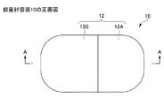
図1は、本発明の第1の実施形態に係る線量計容器10の一例を示す模式図である。より詳しく説明すると、図1Aは、線量計容器10の斜視図である。図1Bは、線量計容器10の正面図であり、図1Cは、図1BのA−A断面図である。図1Dは、線量計容器10の本体部12Aの斜視図であり、図1Eは、線量計容器10の蓋部12Bの斜視図である。また、図1Fは、線量計容器10の収納部11に放射線量計測器51が収納された状態を示す模式図である。1. First embodiment <
FIG. 1 is a schematic diagram showing an example of a
本実施形態に係る線量計容器10は、放射線量計測器を収納する収納部11と、収納部11を囲む遮蔽部12とを備える。 The
〔収納部11〕
収納部11は、放射線量計測器を収納にするための空間を有する。[Storage part 11]
The
放射線量計測器は、中性子線以外の所定の放射線の線量を計測する素子である。所定の放射線は、中性子線以外の放射線の中から任意に選択できるが、ホウ素中性子捕捉療法(BNCT)への応用という観点から、所定の放射線は、ガンマ線であることが好ましい。ただし、ここでいう放射線量計測器は、ガラス線量計を構成する蛍光ガラス素子そのものや前記蛍光ガラス素子が樹脂製のホルダーに収納されたものなど、一連の形態の線量計を含むものとする。 The radiation dose measuring device is an element that measures the dose of a predetermined radiation other than neutron rays. The predetermined radiation can be arbitrarily selected from radiations other than neutron rays, but from the viewpoint of application to boron neutron capture therapy (BNCT), the predetermined radiation is preferably gamma rays. However, the radiation dose measuring device referred to here includes a series of dosimeters such as the fluorescent glass element itself constituting the glass dosimeter and the fluorescent glass element housed in a resin holder.
素子の種類は、特に限定されない。例えば、ガラス線量計を構成する蛍光ガラス素子、フリッケ線量計を構成する硫酸第一鉄又は硫酸第一鉄アンモニウム等が挙げられる。 The type of element is not particularly limited. Examples thereof include a fluorescent glass element that constitutes a glass dosimeter, and ferrous sulfate or ferrous ammonium sulfate that constitutes a Fricke dosimeter.
収納部11の大きさは、特に制限されないが、線量計容器10を小型化するという観点から、収納部11の大きさは、放射線量計測器の大きさと略同じであることが好ましい。 The size of the
例えば、放射線量計測器がガラス線量計を構成する蛍光ガラス素子である場合、収納部11は、φ2.5mm〜3mm、長さ10mm〜15mmの円柱形状である。For example, when the radiation dose measuring device is a fluorescent glass element that constitutes a glass dosimeter, the
〔遮蔽部12〕
遮蔽部12は、収納部11を囲み、線量計容器10に届く中性子線を遮蔽可能に構成される。[Shielding part 12]
The shielding
遮蔽部12は、中性子線を遮蔽する一方、少なくとも、収納部11に収納される放射線量計測器の計測対象である放射線を透過する材料の部材からなる。これにより、放射線量計測器は、線量計容器10の内部に1つあれば足り、線量計容器10の外部に放射線量計測器が未配置であっても、収納部11に収納された放射線量計測器が測定対象の放射線を正確に検出できる。したがって、測定対象の放射線量を計算する手順を簡略化できるとともに、線量計容器10の小型化に寄与し得る。 The
遮蔽部12の材料については、後に詳しく説明する。 The material of the
遮蔽部12の大きさの下限は、遮蔽部12に届く中性子線を好適に遮蔽し、放射線量計測器の計測対象である放射線を好適に透過することができれば、特に限定されない。例えば、遮蔽部12は、収納部11の周囲に、2mm以上の厚さを有することが好ましく、3mm以上の厚さを有することがより好ましい。 The lower limit of the size of the shielding
遮蔽部12の大きさの上限は、特に限定されないが、従来の線量計容器の薄型化、小型化を図る観点から、遮蔽部12は、収納部11の周囲に、8mm以下の厚さを有することが好ましく、5mm以下の厚さを有することがより好ましい。 The upper limit of the size of the shielding
また、遮蔽部12は、少なくとも2つ以上の遮蔽部構成部材を有する。本実施形態では、遮蔽部12は、2つ以上の遮蔽部構成部材として、本体部12A及び蓋部12Bを有する。 Further, the
そして、図1C、図1D及び図1Eから分かるように、隣り合う遮蔽部構成部材である本体部12A及び蓋部12Bは、互いに突き合わせ可能な構造を有する。 Then, as can be seen from FIGS. 1C, 1D, and 1E, the
遮蔽部12を2つ以上の遮蔽部構成部材とし、隣り合う遮蔽部構成部材を互いに突き合わせ可能にすることで、遮蔽部構成部材どうしの着脱が容易となり、放射線量計測器の収納部11への収納、取り外しも容易となる。 By making the shielding
突き合わせ可能な構造の種類は、特に限定されず、図1C、図1D及び図1Eにあるように、本体部12Aと蓋部12Bとを互いに嵌合可能な構造にすることのほか、本体部12Aと蓋部12Bとを突き合わせ、継ぎ目の外側を固定部材で固定すること等が挙げられる。 The type of structure that can be butted is not particularly limited, and as shown in FIGS. 1C, 1D, and 1E, the
中でも、隣り合う遮蔽部構成部材である本体部12Aと蓋部12Bは、互いに嵌合可能な構造を有することが好ましい。嵌合可能にすることで、継ぎ目の外側を固定部材で固定することなく、本体部12Aと蓋部12Bとを一体化できる。また、固定部材に中性子線及び中性子線以外の放射線が照射されることによって起こり得る影響を無視できる。 Above all, it is preferable that the
嵌合可能な構造の種類は、特に限定されず、図1C、図1D及び図1Eにあるように、一方の遮蔽部構成部材(ここでは、本体部12A)を凸形状にし、他方の遮蔽部構成部材(ここでは、蓋部12B)を凹形状にすることのほか、一方の遮蔽部構成部材を所定方向への傾斜部材にし、他方の遮蔽部構成部材を、一方の遮蔽部構成部材とは対称な形状を有する傾斜部材にすることが挙げられる。 The type of structure that can be fitted is not particularly limited, and as shown in FIGS. 1C, 1D, and 1E, one shielding portion constituting member (here, the
中でも、線量計容器10に向けて直線的に照射された中性子線を好適に遮蔽し、測定対象となる放射線を好適に透過させるという観点から、嵌合可能な構造は、図1C、図1D及び図1Eにあるように、一方の遮蔽部構成部材(ここでは、本体部12A)を凸形状にし、他方の遮蔽部構成部材(ここでは、蓋部12B)を凹形状にして形成することが好ましい。 Above all, from the viewpoint of suitably shielding the neutron beam linearly radiated toward the
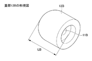
特に、本体部12Aの底部から凸状部材の頂部までの長さLAと、蓋部12Bの底部から凹状部材の頂部までの長さLBとが同じであることが好ましい。LAと、LBとを同じにすることで、同一の厚さの板状体から本体部12A及び蓋部12Bを切り出すことができ、線量計容器10を効率よく製造できるとともに、切削による原料のロスを抑えられる。In particular, it is preferable that the length L A from the bottom of the
上述したとおり、収納部11の大きさは、放射線量計測器の大きさと略同じであることが好ましい。加えて、収納部11は、遮蔽部構成部材(本実施形態では本体部12A及び蓋部12B)の全体にわたって延在することが好ましい。収納部11の大きさが、放射線量計測器の大きさと略同じであり、収納部11が、遮蔽部構成部材の全体にわたって延在することで、突き合わせた遮蔽部構成部材どうしを固定するにあたり、収納部11に収納される放射線量計測器そのものが固定部材として機能し得る。 As described above, the size of the
本体部12Aを凸形状にし、蓋部12Bを凹形状にして本体部12Aと蓋部12Bとを嵌合可能にする場合、本体部12Aが凸状に突出する長さと、蓋部12Bが凹状に凹む深さは、本体部12Aと蓋部12Bとの突き合わせ及び取り外しの容易性、突き合わせた遮蔽部構成部材どうしを固定する強度等の観点から、適宜設定すればよい。 When the
例えば、放射線量計測器がガラス線量計を構成する蛍光ガラス素子である場合、本体部12Aが凸状に突出する長さと、蓋部12Bが凹状に凹む深さとの下限は、1mm以上であることが好ましく、1.5mm以上であることがより好ましく、2mm以上であることがさらに好ましい。本体部12Aが凸状に突出する長さと、蓋部12Bが凹状に凹む深さとが短すぎると、本体部12Aと蓋部12Bとを嵌め合わせても、線量計容器10を使用している間に蓋部12Bが本体部12Aから外れる可能性がある。 For example, when the radiation dose measuring device is a fluorescent glass element forming a glass dosimeter, the lower limit of the length by which the
また、放射線量計測器がガラス線量計を構成する蛍光ガラス素子である場合、本体部12Aが凸状に突出する長さと、蓋部12Bが凹状に凹む深さとの上限は、10mm以下であることが好ましく、5mm以下であることがより好ましく、3mm以下であることがさらに好ましい。本体部12Aが凸状に突出する長さと、蓋部12Bが凹状に凹む深さとが長すぎる場合、切削による原料のロスが大きくなり、コストが増大してしまう。 Further, when the radiation dose measuring device is a fluorescent glass element constituting a glass dosimeter, the upper limit of the length by which the
遮蔽部構成部材の厚みについては、収納部の内表面から遮蔽部構成部材の外表面までの最短距離が一定となるように構成するのが良い。このように構成することで、収納部に収納される放射線量計測器を均一的に遮蔽部構成部材で覆うことができるため、あらゆる方向からの中性子線を等しい割合で遮蔽することができる。したがって、中性子線の照射方向に関わらず、容器に収納した線量計測体の配置パターンを自由自在とすることができる。 With respect to the thickness of the shielding part constituting member, it is preferable that the shortest distance from the inner surface of the housing part to the outer surface of the shielding part constituting member is constant. With such a configuration, the radiation dose measuring instrument housed in the housing can be uniformly covered with the shielding part constituting member, so that neutron rays from all directions can be shielded at an equal rate. Therefore, the arrangement pattern of the dose measuring body housed in the container can be freely set regardless of the irradiation direction of the neutron beam.
また、収納部端部の隅においては、例えば、図5のように、遮蔽部構成部材の厚みが5mmであれば、断面形状から見た遮蔽部構成部材の両端部をR5の曲面とすれば、収納部端部の隅から遮蔽部構成部材の外表面までの最短距離を、等しく5mmとすることができる。このように、遮蔽部構成部材の厚みに応じて、適宜、遮蔽部構成部材の端部のR部の曲面を設計することで、収納部の内表面から遮蔽部構成部材の外表面までの最短距離を一定とすることができる。 Further, at the corner of the end of the storage portion, for example, as shown in FIG. 5, if the thickness of the shielding portion constituting member is 5 mm, both ends of the shielding portion constituting member viewed from the sectional shape may be curved surfaces of R5. The shortest distance from the corner of the end of the storage portion to the outer surface of the shielding portion constituting member can be made equal to 5 mm. In this way, by designing the curved surface of the R portion at the end of the shielding part constituent member as appropriate according to the thickness of the shielding part constituent member, the shortest distance from the inner surface of the storage part to the outer surface of the shielding part constituent member. The distance can be constant.
上記性質を有する材料として、LiF含有材料が挙げられる。中でも、LiF含有率が高く、他の成分が中性子線を透過する影響を受けず、線量計容器10の小型化、薄型化に寄与できることから、LiF含有材料は、LiF焼結体であることが好ましい。 An example of the material having the above properties is a LiF-containing material. Above all, the LiF-containing material is a LiF sintered body because it has a high LiF content and can be contributed to miniaturization and thinning of the
ところで、Liは、6Liと7Liとの2つの安定同位体を含み、天然での存在比は、 7Liが92.5atom%であるのに対し、6Liが7.5atom%である。そのうち、中性子線の遮蔽に寄与するものは、6Liであるので、6Liが濃縮された6LiFを使用することによって、より高い効率で中性子線を遮蔽することができる。そのことから、LiF焼結体は、6LiF焼結体であることがより好ましい。以下、6LiF焼結体について説明する。 By the way, Li is6Li and7It contains two stable isotopes with Li and its abundance in nature is 7While Li is 92.5 atom %,6Li is 7.5 atom %. Among them, those that contribute to the shielding of neutron rays are6Since it is Li,6Li was concentrated6By using LiF, neutron rays can be shielded with higher efficiency. Therefore, the LiF sintered body is6More preferably, it is a LiF sintered body. Less than,6The LiF sintered body will be described.
(6LiF焼結体)
(1)成分:6LiF
6LiF焼結体は、6LiFを主原料としており、他の中性子減速材料・遮蔽材料(例えば、CaF2、MgF2、MgF2−CaF2二元系、MgF2−CaF2−LiF三元系等)に比べて高い中性子遮蔽性能を有する。また、6LiF焼結体は、6LiFからなり、焼結助剤や複合材成分として他の無機化合物が混合されておらず、また、熱可塑性樹脂等との混合物でもない。したがって、本実施形態に係る6LiF焼結体は、極めて高い中性子遮蔽性能を有し、遮蔽部12の薄型化、小型化に寄与し得る。( 6 LiF sintered body)
(1) Component: 6 LiF
The 6 LiF sintered body is mainly composed of 6 LiF, and other neutron moderating materials/shielding materials (for example, CaF 2 , MgF 2 , MgF 2 —CaF 2 binary system, MgF 2 —CaF 2 —LiF ternary). It has a higher neutron shielding performance than other systems. Further, the 6 LiF sintered body is made of 6 LiF, is not mixed with other inorganic compounds as a sintering aid or a composite material component, and is not a mixture with a thermoplastic resin or the like. Therefore, the 6 LiF sintered body according to the present embodiment has extremely high neutron shielding performance, and can contribute to thinning and miniaturization of the shielding
6LiF焼結体において、6Liの純度は、95.0atom%以上、かつ、LiF純度が99wt%以上であることが好ましい。6LiF焼結体に金属成分(元素)等の不純物が多く混在していると、6LiF焼結体に中性子線を照射することによって不純物が放射化し、ガンマ線を放出する可能性がある。6LiFに中性子線が照射されても、放射化は起こらない。よって、本実施形態に係る6LiF焼結体において、6Liが95.0atom%以上、かつ、LiF純度が99wt%以上にすることで、中性子遮蔽性能に優れるだけではなく、人体への被ばくの影響を最小限に抑えられるという利点を有する。 In the 6 LiF sintered body, the purity of 6 Li is preferably 95.0 atom% or more, and the LiF purity is preferably 99 wt% or more. When a large amount of impurities such as metal components (elements) are mixed in the 6 LiF sintered body, the impurities may be activated by irradiating the 6 LiF sintered body with a neutron beam and emit gamma rays. 6 When LiF is irradiated with neutrons, no activation occurs. Therefore, in the 6 LiF sintered body according to the present embodiment, when 6 Li is 95.0 atom% or more and the LiF purity is 99 wt% or more, not only the neutron shielding performance is excellent, but also the human body is exposed to radiation. It has an advantage that the influence can be minimized.
また、6LiFは、焼結体である。6LiF焼結体を製造する手法として、単結晶育成法、融液から凝固させる方法、焼結法等が挙げられる。Further, 6 LiF is a sintered body. 6 Examples of methods for producing a LiF sintered body include a single crystal growing method, a method of solidifying from a melt, and a sintering method.
しかしながら、単結晶育成法は、製造に際して高い制御精度を必要とするため、品質の安定度に劣り、製品価格は極めて高価なものとなる。加えて、得られた成形体は、単結晶であるため、劈開性を有し、加工時にクラックを引き起こしやすい等の課題を有する。 However, the single crystal growing method requires high control accuracy in manufacturing, and thus is inferior in stability of quality and the product price becomes extremely expensive. In addition, since the obtained molded body is a single crystal, it has a cleavability and has a problem that cracks easily occur during processing.
また、融液から凝固させる方法は、冷却時に温度制御を厳密に行う必要があり、かつ冷却に長時間を必要とするため、比較的大きなサイズの全体において均質で健全な固化物を得るのは難しい。 Further, in the method of solidifying from the melt, it is necessary to strictly control the temperature at the time of cooling, and since it takes a long time to cool, it is not possible to obtain a homogeneous and sound solidified product in a relatively large size as a whole. difficult.
6LiF焼結体は、焼結法によって得られているため、高い中性子遮蔽性能を有する中性子遮蔽材を低コストで安定して供給し得る。 Since the 6 LiF sintered body is obtained by a sintering method, a neutron shielding material having high neutron shielding performance can be stably supplied at low cost.
(2)相対密度
6LiF焼結体は、83%以上90%以下の相対密度を有することが好ましい。本実施形態において、相対密度とは、焼結体の密度をLiFの理論密度(2.64g/cm3)で除し、100を掛けた値をいう。(2) Relative density
The 6 LiF sintered body preferably has a relative density of 83% or more and 90% or less. In the present embodiment, the relative density means a value obtained by dividing the density of the sintered body by the theoretical density of LiF (2.64 g/cm 3 ) and multiplying by 100.
相対密度は、83%以上90%以下であり、6LiF焼結体は、高密度化されていない。そのため、6LiF焼結体は、切削加工性に優れるという利点がある。The relative density is 83% or more and 90% or less, and the 6 LiF sintered body is not densified. Therefore, the 6 LiF sintered body has an advantage that it has excellent machinability.
相対密度が小さすぎると、6LiF焼結体が十分な中性子遮蔽性能を有しない可能性がある。また、相対密度が小さすぎると、焼結体内部の空隙の割合が高く、機械的強度に劣り、加工中の破損等が懸念される。If the relative density is too low, the 6 LiF sintered body may not have sufficient neutron shielding performance. On the other hand, if the relative density is too low, the ratio of voids inside the sintered body is high, the mechanical strength is inferior, and there is a risk of damage during processing.
これに対し、相対密度が大きすぎると、6LiF焼結体が十分な中性子遮蔽能を有するとはいえるものの、焼結体の緻密性が高いため、焼結体を加工する際、材料内部の残留応力が解放されることで、クラック等を生じることが懸念される。On the other hand, if the relative density is too large, it can be said that the 6 LiF sintered body has a sufficient neutron shielding ability, but since the sintered body has high denseness, when the sintered body is processed, When the residual stress is released, there is a concern that cracks may occur.
(3)厚さ
6LiF焼結体の厚さは、中性子線を好適に遮蔽できる厚さであれば、特に限定されるものではない。具体的に、6LiF焼結体の厚さは、2mm以上であることが好ましく、3mm以上であることがより好ましい。(3) Thickness
The thickness of the 6 LiF sintered body is not particularly limited as long as it can suitably shield neutron rays. Specifically, the thickness of the 6 LiF sintered body is preferably 2 mm or more, and more preferably 3 mm or more.
6LiF焼結体の厚さの上限は、特に限定されないが、遮蔽部12の小型化、軽量化を図る観点から、中性子線を好適に遮蔽できる範囲において、6LiF焼結体は、薄い方が好ましい。具体的に、6LiF焼結体の厚さは、8mm以下であることが好ましく、5mm以下であることがより好ましい。The upper limit of the thickness of the 6 LiF sintered body is not particularly limited, but from the viewpoint of reducing the size and weight of the shielding
(6LiF焼結体の製造方法)
本実施形態に係る6LiF焼結体の製造方法は、6LiF粉末と有機系成形助剤とを含有する6LiF組成物を加圧し、プレス成形体を得る加圧工程と、このプレス成形体を630℃以上、830℃以下で焼成する焼成工程とを含む。また、焼成工程に先立ち、250℃以上350℃以下で予備焼成する予備焼成工程を入れても良い。( 6 Method for manufacturing LiF sintered body)
The method for producing a 6 LiF sintered body according to the present embodiment includes a pressurizing step of pressurizing a 6 LiF composition containing 6 LiF powder and an organic molding aid to obtain a press molded body, and the press molded body. Firing step of firing at 630° C. or higher and 830° C. or lower. In addition, prior to the firing step, a preliminary firing step of performing preliminary firing at 250° C. or higher and 350° C. or lower may be performed.
<線量計測体1>
図1Fは、本発明の第1の実施形態に係る線量計測体1の一例を示す模式図である。この線量計1では、線量計容器10の収納部11に放射線量計測器51が収納されている。<Dose measurement unit 1>
FIG. 1F is a schematic diagram showing an example of a dose measuring body 1 according to the first embodiment of the present invention. In this dosimeter 1, the radiation
本実施形態によると、線量計容器10の厚みを薄く構成しても、十分な中性子遮蔽性能を得ることができ、線量計容器10のサイズも小さく設計することができる。したがって、線量計容器10の取り扱いが容易となり、例えば測定現場においても、小さな線量計容器10であれば、中性子線照射領域に複数配置して、中性子照射スペース領域内におけるガンマ線の有無や強弱の違いを(もしくは測定作業工程を少なくして)測定することもできる。 According to this embodiment, even if the
また、線量計容器10の構成部材である遮蔽部12は、中性子線を遮蔽する一方、少なくとも、収納部11に収納される放射線量計測器の計測対象である放射線を透過する材料の部材からなる。これにより、収納部11に収納された放射線量計測器が測定対象の放射線を正確に検出できる。したがって、測定対象の放射線量を計算する手順を簡略化できるとともに、線量計容器10の小型化に寄与し得る。 Further, the shielding
2.第2の実施形態
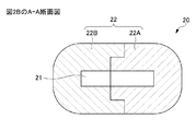
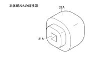
図2は、本発明の第2の実施形態に係る線量計容器20の一例を示す模式図である。より詳しく説明すると、図2Aは、線量計容器10の斜視図である。図2Bは、線量計容器20の正面図であり、図2Cは、図2BのA−A断面図である。図2Dは、線量計容器20の本体部22Aの斜視図であり、図2Eは、線量計容器20の蓋部22Bの斜視図である。また、図2Fは、本発明の第2の実施形態に係る線量計測体2の一例を示す模式図であり、線量計容器20の収納部21に放射線量計測器51が収納されている。2. Second Embodiment FIG. 2 is a schematic diagram showing an example of a
線量計容器2は、収納部21と、遮蔽部22とを備える。収納部21は、中性子線以外の所定の放射線の線量を計測する放射線量計測器を収納する部材であり、特に説明がない限り、収納部11と同様の機能を有する。遮蔽部22は、収納部21を囲む部材であり、特に説明がない限り、遮蔽部12と同様の機能を有する。 The
第1の実施形態と第2の実施形態とを対比すると、第1の実施形態では、線量計容器10の全体の形状が、円柱形状の周壁の両端に半球形状の両端部が配設されたカプセル形状であったのに対し、第2の実施形態では、線量計容器20の全体の形状が、四角柱形状を基本として角に丸みを帯びた形状である点で異なる。 Comparing the first embodiment and the second embodiment, in the first embodiment, the entire shape of the
また、第1の実施形態では、収納部21の形状が、放射線量計測器51(例えば、蛍光ガラス素子)の形状に合わせて円柱形状であったのに対し、第2の実施形態では、収納部21の形状が、放射線量計測器51の底面の外径の長さを底面の1辺の長さとし、放射線量計測器51の高さと略同じ長さを高さとする四角柱形状である点で異なる。 Further, in the first embodiment, the shape of the
このように、線量計容器の形状は、特に限定されるものではなく、適宜選択可能である。 As described above, the shape of the dosimeter container is not particularly limited and can be appropriately selected.
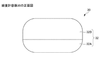
3.第3の実施形態
図3は、本発明の第3の実施形態に係る線量計容器30の一例を示す模式図である。より詳しく説明すると、図3Aは、線量計容器30の斜視図であり、図3Bは、線量計容器30の正面図である。図3Cは、線量計容器30の平面図であり、図3Dは、図3CのA−A断面図である。図3Eは、線量計容器30の本体部32Aの斜視図であり、図3Fは、線量計容器30の蓋部32Bの斜視図である。また、図3Gは、本発明の第3の実施形態に係る線量計測体3の一例を示す模式図であり、線量計容器30の収納部31に放射線量計測器51が収納されている。3. Third Embodiment FIG. 3 is a schematic diagram showing an example of a
線量計容器3は、収納部31と、遮蔽部32とを備える。収納部31は、中性子線以外の所定の放射線の線量を計測する放射線量計測器を収納する部材であり、特に説明がない限り、収納部11と同様の機能を有する。遮蔽部32は、収納部31を囲む部材であり、特に説明がない限り、遮蔽部12と同様の機能を有する。 The
第1の実施形態と第3の実施形態とを対比すると、第1の実施形態では、線量計容器10の全体の形状が、上述したカプセル形状であったのに対し、第3の実施形態では、線量計容器30の全体の形状が、円形平板状である点で異なる。 Comparing the first embodiment and the third embodiment, in the first embodiment, the overall shape of the
また、第1の実施形態では、収納部21の形状が、放射線量計測器51(例えば、蛍光ガラス素子)の形状に合わせて円柱形状であったのに対し、第3の実施形態では、収納部31の形状が、放射線量計測器51の長手方向の長さと略同じ長さを内径とする円形平板状である点で異なる。 In addition, in the first embodiment, the shape of the
また、第1の実施形態では、収納部11は、遮蔽部構成部材51(本実施形態では本体部12A及び蓋部12B)の全体にわたって延在するのに対し、第3の実施形態では、収納部31は、本体部32Aのみに位置し、蓋部32Bに位置しない点で異なる。 In addition, in the first embodiment, the
このように、線量計容器の形状は、特に限定されるものではなく、適宜選択可能である。中でも、遮蔽部構成部材51を本体部と蓋部とが嵌合したときの固定部材として機能できることを考慮すると、第1実施形態にあるように、収納部は、遮蔽部構成部材51の全体にわたって延在するが好ましい。 As described above, the shape of the dosimeter container is not particularly limited and can be appropriately selected. In particular, considering that the shielding
4.第4の実施形態
図4は、本発明の第4の実施形態に係る線量計容器40の一例を示す模式図である。より詳しく説明すると、図4Aは、線量計容器40の斜視図であり、図4Bは、線量計容器40の正面図である。図4Cは、線量計容器40の平面図であり、図4Dは、図4CのA−A断面図である。図4Eは、線量計容器40の本体部42Aの斜視図であり、図4Fは、線量計容器40の蓋部42Bの斜視図である。また、図4Gは、本発明の第4の実施形態に係る線量計測体4の一例を示す模式図であり、線量計容器40の収納部41に放射線量計測器51が収納されている。4. Fourth Embodiment FIG. 4 is a schematic diagram showing an example of a
線量計容器4は、収納部41と、遮蔽部42とを備える。収納部41は、中性子線以外の所定の放射線の線量を計測する放射線量計測器を収納する部材であり、特に説明がない限り、収納部11と同様の機能を有する。遮蔽部42は、収納部41を囲む部材であり、特に説明がない限り、遮蔽部42と同様の機能を有する。 The dosimeter container 4 includes a
第3の実施形態と第4の実施形態とを対比すると、第3の実施形態では、線量計容器30の全体の形状が、円形平板状であったのに対し、第4の実施形態では、線量計容器40の全体の形状が、略正方形の平板状である点で異なる。 Comparing the third embodiment and the fourth embodiment, in the third embodiment, the overall shape of the
このように、線量計容器の形状は、特に限定されるものではなく、適宜選択可能である。 As described above, the shape of the dosimeter container is not particularly limited and can be appropriately selected.
以下、実施例により、本発明をさらに詳細に説明するが、本発明はこれらの実施例に何ら限定されるものではない。 Hereinafter, the present invention will be described in more detail with reference to Examples, but the present invention is not limited to these Examples.
<線量計容器10の製造>
以下の工程を経て、本発明の第1の実施形態に係る線量計容器10と同様の形状を有し、正面視したときの断面形状(図1Cに相当)が図5に示す寸法である線量計容器10を得た。<Manufacture of
A dose having the same shape as the
〔6LiF焼結体の製造〕
以下の工程を経て、高さ約16mmの円柱状の6LiF焼結体を得た。[Production of 6 LiF Sintered Body]
Through the following steps, a cylindrical 6 LiF sintered body having a height of about 16 mm was obtained.
まず、6LiF粉末(6Li純度95.0atom%、LiF99%:Sigma―Aldrich製)100質量部と、ステアリン酸とセルロースからなる成形助剤16質量部とを混合し、6LiF組成物を得た。First, 100 parts by mass of 6 LiF powder ( 6 Li purity 95.0 atom %, LiF 99%: manufactured by Sigma-Aldrich) and 16 parts by mass of a molding aid composed of stearic acid and cellulose are mixed to obtain a 6 LiF composition. It was
(1)加圧工程
次いで、直径25mmの金型に6LiF組成物を約15.8g充填し、タッピングにより6LiF組成物の空隙を減らした。(1) pressurization step Subsequently, about 15.8g filled with 6 LiF composition in a mold with a diameter of 25 mm, reduced the gap 6 LiF composition by tapping.
次いで、円柱状の金型を油圧式のプレス機に装填し、100MPaのプレス圧をかけて、プレス成形体を得た。 Next, the cylindrical mold was loaded into a hydraulic press machine, and a press pressure of 100 MPa was applied to obtain a press-molded body.
(2)予備焼成工程
それぞれのプレス成形体を大気雰囲気の炉に入れた。300℃まで100℃/hrで昇温させ、5時間保持することで、プレス成形体に含まれる成形助剤の大半を分解・揮散させた。(2) Pre-baking step Each press-molded body was placed in a furnace in an air atmosphere. By raising the temperature to 300° C. at 100° C./hr and holding it for 5 hours, most of the molding aid contained in the press-molded body was decomposed and volatilized.
(3)焼成工程
予備焼成工程の後、プレス成形体を650℃まで100℃/hrで昇温し、5時間保持した。その後、冷却(空冷)を行い、6LiF焼結体を得た。(3) Firing Step After the pre-firing step, the press-formed product was heated to 650° C. at 100° C./hr and held for 5 hours. Then, cooling (air cooling) was performed to obtain a 6 LiF sintered body.
〔6LiF焼結体の加工〕
続いて、6LiF焼結体に対し、マシニング加工により、断面形状が図5に示す寸法になるように、6LiF焼結体の周囲及び内部を切削、穴あけし、実施例に係る線量計容器10を得た。[ 6 Processing of LiF sintered body]
Subsequently, the 6 LiF sintered body was subjected to machining to cut and punch the periphery and the inside of the 6 LiF sintered body so that the cross-sectional shape had the dimensions shown in FIG. 5, and the dosimeter container according to the example.
<評価>
〔プレス成形体の評価〕
加圧工程によって得られたプレス成形体の6LiF換算の相対密度は、57.3%であった。また、外観を目視したところ、膨れやクラックは認められなかった。<Evaluation>
[Evaluation of press-formed product]
The relative density of the press-molded body obtained by the pressing step in terms of 6 LiF was 57.3%. In addition, when the appearance was visually observed, no swelling or cracks were observed.
〔6LiF焼結体の評価〕
また、加圧工程、予備焼成工程及び焼成工程によって得られた6LiF焼結体の質量は13.6g、相対密度は86.2%であった。また外観を目視したところ、膨れやクラックは認められなかった。また、6LiF焼結体を精密切断機で切断し、切断面の状態を目視したところ、クラックやボイド等の内部欠陥も認められなかった。[Evaluation of 6 LiF Sintered Body]
In addition, the mass of the 6 LiF sintered body obtained by the pressurizing step, the preliminary firing step and the firing step had a mass of 13.6 g and a relative density of 86.2%. In addition, when the appearance was visually observed, no swelling or cracks were observed. Further, when the 6 LiF sintered body was cut with a precision cutting machine and the state of the cut surface was visually observed, internal defects such as cracks and voids were not recognized.
〔線量計容器10の評価〕
線量計容器10の収納部11に、蛍光ガラス素子を収納し、線量計容器10の外部から遮蔽部12に向けてガンマ線及び中性子線を照射した。その結果、線量計容器10は、中性子線の遮蔽性に優れる一方で、ガンマ線の透過性を備えており、ガンマ線量の計測に好適であることが確認された。[Evaluation of dosimeter container 10]
A fluorescent glass element was housed in the
1 第1の実施形態に係る線量計測体
10 第1の実施形態に係る線量計容器
11 収納部
12 遮蔽部
12A 本体部
12B 蓋部
2 第2の実施形態に係る線量計測体
20 第2の実施形態に係る線量計容器
3 第3の実施形態に係る線量計測体
30 第3の実施形態に係る線量計容器
4 第4の実施形態に係る線量計測体
40 第4の実施形態に係る線量計容器
51 放射線量計測器1
Claims (7)
前記収納部の周囲全体を囲み、かつ、少なくとも、前記放射線量計測器の計測対象である前記所定の放射線を透過し、中性子線を遮蔽するLiF焼結体からなる遮蔽部とを備える線量計容器であって、
前記LiF焼結体は、6LiFからなり、83%以上90%以下の相対密度を有し、前記LiF焼結体において、6Liの純度が95.0atom%以上、かつ、LiF純度が99wt%以上である、線量計容器。 A storage unit that stores a radiation dose measuring device that measures the dose of predetermined radiation other than neutron rays,
A dosimeter container that surrounds the entire circumference of the storage portion, and includes at least a shield portion that is made of a LiF sintered body that transmits the predetermined radiation that is a measurement target of the radiation dose measuring instrument and shields neutron rays. And
The LiF sintered body is made of 6 LiF and has a relative density of 83% or more and 90% or less. In the LiF sintered body, the purity of 6 Li is 95.0 atom% or more and the LiF purity is 99 wt%. The above is the dosimeter container.
前記収納部は、前記遮蔽部構成部材の全体にわたって延在する、請求項3又は4に記載の線量計容器。 The size of the storage unit is substantially the same as or larger than the size of the radiation dose measuring instrument,
The dosimeter container according to claim 3 or 4, wherein the storage portion extends over the entire shielding portion constituent member.
Applications Claiming Priority (3)
| Application Number | Priority Date | Filing Date | Title |
|---|---|---|---|
| JPPCT/JP2017/013684 | 2017-03-31 | ||
| PCT/JP2017/013684 WO2018179363A1 (en) | 2017-03-31 | 2017-03-31 | Dosimeter housing and dosimetry body |
| PCT/JP2018/012576 WO2018181395A1 (en) | 2017-03-31 | 2018-03-27 | Dosimeter container and dose measuring body |
Publications (2)
| Publication Number | Publication Date |
|---|---|
| JPWO2018181395A1 JPWO2018181395A1 (en) | 2019-04-11 |
| JP6734368B2 true JP6734368B2 (en) | 2020-08-05 |
Family
ID=63674532
Family Applications (1)
| Application Number | Title | Priority Date | Filing Date |
|---|---|---|---|
| JP2018517656A Active JP6734368B2 (en) | 2017-03-31 | 2018-03-27 | Dosimeter container and dosimeter |
Country Status (14)
| Country | Link |
|---|---|
| US (1) | US10877165B2 (en) |
| EP (1) | EP3407092B1 (en) |
| JP (1) | JP6734368B2 (en) |
| KR (1) | KR102068919B1 (en) |
| CN (1) | CN108990421A (en) |
| AR (1) | AR111299A1 (en) |
| AU (1) | AU2018202844B2 (en) |
| ES (1) | ES2811032T3 (en) |
| IL (1) | IL259290A (en) |
| PL (1) | PL3407092T3 (en) |
| RU (1) | RU2700378C1 (en) |
| SG (1) | SG11201803343SA (en) |
| TW (1) | TWI669525B (en) |
| WO (2) | WO2018179363A1 (en) |
Families Citing this family (5)
| Publication number | Priority date | Publication date | Assignee | Title |
|---|---|---|---|---|
| SG11202003316RA (en) * | 2017-10-11 | 2020-05-28 | Nippon Light Metal Co | Shield adhesive having neutron shielding properties |
| CN110571224B (en) * | 2019-08-05 | 2021-12-28 | 深圳市华星光电半导体显示技术有限公司 | Display device and method for manufacturing the same |
| TWI790709B (en) | 2021-04-16 | 2023-01-21 | 國立大學法人筑波大學 | Sintered body for radiation shielding material, radiation shielding material, and method for producing the same |
| CN113917516A (en) * | 2021-10-13 | 2022-01-11 | 散裂中子源科学中心 | Method for measuring spatial distribution of multiple dose components in BNCT |
| WO2024142755A1 (en) * | 2022-12-27 | 2024-07-04 | 国立大学法人大阪大学 | Measuring device and measuring method for measuring effectiveness of boron neutron capture therapy |
Family Cites Families (17)
| Publication number | Priority date | Publication date | Assignee | Title |
|---|---|---|---|---|
| US3426197A (en) | 1965-07-16 | 1969-02-04 | Electrospace Corp | Dosimeter for measuring neutron and gamma radiation |
| JPS5194098A (en) * | 1975-02-14 | 1976-08-18 | SHOKETSUFUTSUKARICHIUMUCHUSEISHAHEIZAIRYO | |
| JPS5529104Y2 (en) | 1977-07-07 | 1980-07-11 | ||
| US4171485A (en) * | 1977-09-22 | 1979-10-16 | Mdh Industries, Inc. | Apparatus for analyzing the spectral data in an elemental analyzer measuring gamma rays arising from neutron capture in bulk substances |
| US4346511A (en) | 1979-07-05 | 1982-08-31 | The United States Of America As Represented By The United States Department Of Energy | Method for preparing dosimeter for measuring skin dose |
| SU1144503A1 (en) * | 1983-10-21 | 1985-08-30 | Рижский Медицинский Институт | Thermoluminescent dosimeter of mixed gamma and neutron radiation |
| JPH08201581A (en) | 1995-01-30 | 1996-08-09 | Sutaaraito Kogyo Kk | Composition for radiation shield and its usage |
| JP2001294853A (en) * | 2000-04-12 | 2001-10-23 | Hitachi Medical Corp | Oxide fluorescent substance, radiation detector using the same, and x-ray ct apparatus |
| JP2003215247A (en) * | 2002-01-29 | 2003-07-30 | Hitachi Ltd | Neutron dosage measuring service method |
| CA2528177A1 (en) * | 2003-06-05 | 2004-12-16 | Niton Llc | Neutron and gamma ray monitor |
| EP2140913A1 (en) | 2008-07-03 | 2010-01-06 | Ion Beam Applications S.A. | Device and method for particle therapy verification |
| US8431885B2 (en) | 2010-05-19 | 2013-04-30 | Schlumberger Technology Corporation | Gamma-ray detectors for downhole applications |
| WO2012064797A2 (en) * | 2010-11-11 | 2012-05-18 | Schlumberger Canada Limited | Neutron-gamma density through normalized inelastic ratio |
| DE102011054846B3 (en) | 2011-10-27 | 2013-02-21 | Gsi Helmholtzzentrum Für Schwerionenforschung Gmbh | Local dosimeter for measuring the ambient dose equivalent with a simple structure |
| JP6223882B2 (en) * | 2014-03-18 | 2017-11-01 | 住友重機械工業株式会社 | Neutron capture therapy system |
| JP6369829B2 (en) * | 2014-06-13 | 2018-08-08 | 三菱重工機械システム株式会社 | Gamma ray measurement apparatus and gamma ray measurement method |
| RU2682972C1 (en) * | 2015-05-04 | 2019-03-25 | Неуборон Медтек Лтд. | Applied in the neutron capture therapy beam formation element |
-
2017
- 2017-03-31 WO PCT/JP2017/013684 patent/WO2018179363A1/en active Application Filing
-
2018
- 2018-03-26 TW TW107110257A patent/TWI669525B/en active
- 2018-03-27 RU RU2018123313A patent/RU2700378C1/en active
- 2018-03-27 CN CN201880000503.5A patent/CN108990421A/en not_active Withdrawn
- 2018-03-27 ES ES18729857T patent/ES2811032T3/en active Active
- 2018-03-27 PL PL18729857T patent/PL3407092T3/en unknown
- 2018-03-27 EP EP18729857.5A patent/EP3407092B1/en active Active
- 2018-03-27 WO PCT/JP2018/012576 patent/WO2018181395A1/en active Application Filing
- 2018-03-27 US US15/777,164 patent/US10877165B2/en active Active
- 2018-03-27 AR ARP180100739A patent/AR111299A1/en unknown
- 2018-03-27 KR KR1020187013783A patent/KR102068919B1/en active IP Right Grant
- 2018-03-27 SG SG11201803343SA patent/SG11201803343SA/en unknown
- 2018-03-27 AU AU2018202844A patent/AU2018202844B2/en not_active Ceased
- 2018-03-27 JP JP2018517656A patent/JP6734368B2/en active Active
- 2018-05-10 IL IL259290A patent/IL259290A/en unknown
Also Published As
| Publication number | Publication date |
|---|---|
| US20200124743A1 (en) | 2020-04-23 |
| EP3407092B1 (en) | 2020-05-20 |
| TWI669525B (en) | 2019-08-21 |
| JPWO2018181395A1 (en) | 2019-04-11 |
| EP3407092A1 (en) | 2018-11-28 |
| TW201842354A (en) | 2018-12-01 |
| CN108990421A (en) | 2018-12-11 |
| AU2018202844A1 (en) | 2018-10-18 |
| AR111299A1 (en) | 2019-06-26 |
| WO2018181395A1 (en) | 2018-10-04 |
| PL3407092T3 (en) | 2021-05-04 |
| EP3407092A4 (en) | 2019-05-08 |
| IL259290A (en) | 2019-02-28 |
| US10877165B2 (en) | 2020-12-29 |
| WO2018179363A1 (en) | 2018-10-04 |
| RU2700378C1 (en) | 2019-09-16 |
| AU2018202844B2 (en) | 2019-11-28 |
| KR20180119552A (en) | 2018-11-02 |
| SG11201803343SA (en) | 2018-11-29 |
| KR102068919B1 (en) | 2020-01-21 |
| ES2811032T3 (en) | 2021-03-10 |
Similar Documents
| Publication | Publication Date | Title |
|---|---|---|
| JP6734368B2 (en) | Dosimeter container and dosimeter | |
| CN104640824B (en) | Manufacture method for the fluoride sintered body of neutron ray decelerating material | |
| CN106145950A (en) | MgF for lonizing radiation decelerating material2-CaF2binary system sintered body and manufacture method thereof | |
| EP2894638A1 (en) | Solidified radioactive waste and method for manufacturing same | |
| US11062814B1 (en) | Box-type structure having shielding function | |
| KR102558235B1 (en) | Sintered body for radiation shielding material, radiation shielding material, and method for producing the same | |
| KR101452790B1 (en) | Californium neutron source container with optimum lead shielding | |
| US20090194712A1 (en) | Passive Actinide Self-Burner | |
| Badhwar et al. | Alterations in dose and lineal energy spectra under different shieldings in the Los Alamos high-energy neutron field | |
| JP7165339B2 (en) | Sintered body for radiation shielding material, radiation shielding material and method for producing the same | |
| Golnik et al. | Irradiation facilities for BNCT at research reactor MARIA in Poland | |
| CN110967720A (en) | Human body radiation tissue equivalent material and dose measurement model | |
| Sato et al. | Attachment of 31Cl and 39Cl induced by high-energy neutrons to coexisted aerosols | |
| Strinning et al. | Visual inspection of a copper collimator irradiated by 590 MeV protons at PSI | |
| Sono et al. | Assessment of human body surface and internal dose estimations in criticality accidents based on experimental and computational simulations | |
| Brockman et al. | Performance of a New Composite Single-Crystal Filtered Thermal Neutron Beam for Neutron Capture Therapy Research at the University of Missouri | |
| Hemmendinger et al. | Tritium production in a sphere of/sup 6/LiD irradiated by 14-MeV neutrons |
Legal Events
| Date | Code | Title | Description |
|---|---|---|---|
| A621 | Written request for application examination |
Free format text: JAPANESE INTERMEDIATE CODE: A621 Effective date: 20180405 |
|
| A131 | Notification of reasons for refusal |
Free format text: JAPANESE INTERMEDIATE CODE: A131 Effective date: 20181218 |
|
| A601 | Written request for extension of time |
Free format text: JAPANESE INTERMEDIATE CODE: A601 Effective date: 20190218 |
|
| A521 | Request for written amendment filed |
Free format text: JAPANESE INTERMEDIATE CODE: A523 Effective date: 20190222 |
|
| A02 | Decision of refusal |
Free format text: JAPANESE INTERMEDIATE CODE: A02 Effective date: 20190319 |
|
| A521 | Request for written amendment filed |
Free format text: JAPANESE INTERMEDIATE CODE: A523 Effective date: 20190628 |
|
| A601 | Written request for extension of time |
Free format text: JAPANESE INTERMEDIATE CODE: A601 Effective date: 20200309 |
|
| A521 | Request for written amendment filed |
Free format text: JAPANESE INTERMEDIATE CODE: A523 Effective date: 20200409 |
|
| A521 | Request for written amendment filed |
Free format text: JAPANESE INTERMEDIATE CODE: A821 Effective date: 20200410 |
|
| A61 | First payment of annual fees (during grant procedure) |
Free format text: JAPANESE INTERMEDIATE CODE: A61 Effective date: 20200709 |
|
| R150 | Certificate of patent or registration of utility model |
Ref document number: 6734368 Country of ref document: JP Free format text: JAPANESE INTERMEDIATE CODE: R150 |
|
| R250 | Receipt of annual fees |
Free format text: JAPANESE INTERMEDIATE CODE: R250 |