JP6731714B2 - Blower - Google Patents

Blower Download PDF

Info

Publication number
JP6731714B2
JP6731714B2 JP2015197361A JP2015197361A JP6731714B2 JP 6731714 B2 JP6731714 B2 JP 6731714B2 JP 2015197361 A JP2015197361 A JP 2015197361A JP 2015197361 A JP2015197361 A JP 2015197361A JP 6731714 B2 JP6731714 B2 JP 6731714B2
Authority
JP
Japan
Prior art keywords
cylinder
fan
filter
screen
noise
Prior art date
Legal status (The legal status is an assumption and is not a legal conclusion. Google has not performed a legal analysis and makes no representation as to the accuracy of the status listed.)
Active
Application number
JP2015197361A
Other languages
Japanese (ja)
Other versions
JP2017070335A5 (en
JP2017070335A (en
Inventor
泰秀 友寄
泰秀 友寄
岡本 祐介
祐介 岡本
武志 濱田
武志 濱田
Current Assignee (The listed assignees may be inaccurate. Google has not performed a legal analysis and makes no representation or warranty as to the accuracy of the list.)
Maxell Holdings Ltd
Original Assignee
Maxell Holdings Ltd
Priority date (The priority date is an assumption and is not a legal conclusion. Google has not performed a legal analysis and makes no representation as to the accuracy of the date listed.)
Filing date
Publication date
Application filed by Maxell Holdings Ltd filed Critical Maxell Holdings Ltd
Priority to JP2015197361A priority Critical patent/JP6731714B2/en
Priority to PCT/JP2016/076648 priority patent/WO2017061236A1/en
Priority to CN201680050654.2A priority patent/CN108024610A/en
Publication of JP2017070335A publication Critical patent/JP2017070335A/en
Publication of JP2017070335A5 publication Critical patent/JP2017070335A5/ja
Application granted granted Critical
Publication of JP6731714B2 publication Critical patent/JP6731714B2/en
Active legal-status Critical Current
Anticipated expiration legal-status Critical

Links

Images

Landscapes

  • Cleaning And Drying Hair (AREA)

Description

本発明は、吸込口に吸込みグリルが設けてあるヘアードライヤー等の送風装置に関し、とくに、使用時の送風騒音の騒音量を低減できるようにした送風装置に関する。 The present invention relates to a blower device such as a hair dryer having a suction grill provided at a suction port, and more particularly to a blower device capable of reducing the amount of blown noise during use.

本発明に関して、吸込口を内外2重の吸込グリルで覆うグリル構造は特許文献1の加熱送風装置に公知である。そこでは、丸筒状の本体部の吸入口に、ベルマウス状の枠内面を備えたフィルター取付け枠を着脱可能に装着し、その内周面と外周面のそれぞれに内フィルターと外フィルターを配置している。内フィルターと外フィルターは、いずれも金属製のメッシュ材を素材にして、外膨らみドーム状に形成してある。 With respect to the present invention, a grill structure in which the suction port is covered with double suction grilles inside and outside is known in the heating blower of Patent Document 1. There, a filter mounting frame having a bellmouth-shaped frame inner surface is detachably attached to the inlet of the round tubular main body, and an inner filter and an outer filter are arranged on each of the inner peripheral surface and the outer peripheral surface. doing. Each of the inner filter and the outer filter is made of a metal mesh material and formed into a dome shape with an outer bulge.

本発明に係るヘアードライヤーにおいては、送風ファンに隣接して配置した吸込みグリルを、内凹みドーム状に形成するが、こうしたグリル構造は特許文献2に公知である。そこでは、円筒状の吸気口に内凹みドーム状の吸気口ガード(吸込みグリル)を取付けている。また、本体ケースの内径に対するファンの外径を80%以下にして、ファンとファンガイドの間の摩擦渦流の発生を解消して渦音(騒音)を低減している。 In the hair dryer according to the present invention, the suction grill disposed adjacent to the blower fan is formed in the shape of an inwardly recessed dome, and such a grill structure is known in Patent Document 2. There, an indented dome-shaped intake port guard (suction grille) is attached to the cylindrical intake port. Further, the outer diameter of the fan with respect to the inner diameter of the main body case is set to 80% or less to eliminate the generation of frictional vortex between the fan and the fan guide and reduce the vortex sound (noise).

特開2009−028437号公報(段落番号0022、図5)JP, 2009-028437, A (paragraph number 0022, Drawing 5). 特開昭59−118105号公報(2頁左欄9〜11行、第1図)JP-A-59-118105 (page 2, left column, lines 9 to 11, FIG. 1)

特許文献1の加熱送風装置によれば、内外2重の内フィルターと外フィルターで塵芥の侵入を防止して塵芥除去性能を向上できる。また、フィルター取付け枠の枠内面がベルマウス状に形成してあるので、枠内面における通風抵抗を減らして風量を増大できる。しかし、特許文献1の加熱送風装置は、塵芥除去性能の向上のために内フィルターと外フィルターを設けているにすぎず、送風騒音の低減に言及した記載は見当たらない。 According to the heating air blower of Patent Document 1, it is possible to prevent dust from entering with the double inner and outer filters and the outer filter to improve dust removal performance. Further, since the inner surface of the frame of the filter mounting frame is formed in a bell mouth shape, it is possible to reduce the ventilation resistance on the inner surface of the frame and increase the air volume. However, the heating air blower of Patent Document 1 merely provides an inner filter and an outer filter in order to improve the dust removal performance, and there is no description mentioning reduction of air blow noise.

特許文献2のヘアードライヤーでは、本体ケースの内径に対するファンの外径を80%以下にし、ファンとファンガイドの間の摩擦渦流の発生を解消して渦音(騒音)を低減している。しかし、特許文献1の加熱送風装置と同様に、吸気口ガードと送風騒音の騒音量を低減することに関して、両者の関連性に言及した記載はない。 In the hair dryer of Patent Document 2, the outer diameter of the fan relative to the inner diameter of the main body case is set to 80% or less, and the generation of friction vortex flow between the fan and the fan guide is eliminated to reduce vortex noise (noise). However, like the heating air blower of Patent Document 1, regarding the reduction of the noise amount of the air intake guard and the air blow noise, there is no description that mentions the relationship between the two.

近年のヘアードライヤーは、乾燥能力の向上のために高出力で大量の乾燥風を送給できることと、扱いやすさのために小形でコンパクトであることが求められている。乾燥風を大風量化するには、送風ファンのファン径を大きくするのが効果的であるが、そうすると送風部分が大形化するため、ヘアードライヤーを小形化しコンパクト化することができない。多くの場合には、送風ファンのファン径を小さいままにして、駆動回転数を増強することで、ヘアードライヤーの乾燥風を大風量化している。しかし、送風ファンの駆動回転数を増加すると、ヘアードライヤーの騒音量が増加するのを避けられず、とくに、送風ファンの駆動回転数が10000rpm前後になると、送風ファンに吸込まれる空気速度が大きくなることもあって、大きく耳障りな送風騒音が生じやすい。 Hair dryers in recent years are required to be capable of delivering a large amount of dry air with high output in order to improve the drying capacity, and to be small and compact for easy handling. In order to increase the dry air volume, it is effective to increase the fan diameter of the blower fan, but if this is done, the blower part becomes large and the hair dryer cannot be made compact and compact. In many cases, the drying air of the hair dryer is made large by increasing the driving speed by keeping the fan diameter of the blower fan small. However, when the driving rotation speed of the blower fan is increased, the noise amount of the hair dryer is unavoidably increased. Especially, when the driving rotation speed of the blower fan is around 10,000 rpm, the air velocity sucked into the blower fan becomes large. As a result, a large irritating blast noise is likely to occur.

本発明の目的は、送風騒音を大幅に抑止して装置全体の騒音を減少し静音化できる送風装置を提供することにある。
本発明の目的は、吸込みグリルおよび送風ファンの構造を改良して送風騒音を大幅に抑止でき、従来の騒音防止構造に比べて低コストで全体騒音を減少し静音化できる送風装置を提供することにある。
An object of the present invention is to provide a blower device that can significantly suppress the blower noise and reduce the noise of the entire device to reduce the noise.
An object of the present invention is to provide a blower device which can improve the structures of a suction grill and a blower fan to significantly suppress the blower noise, and can reduce the overall noise and reduce the noise at a lower cost than a conventional noise prevention structure. It is in.

ヘアードライヤー等の送風装置の騒音の殆どは、送風ファンが回転することで発生する騒音(回転騒音)と、送風ファンのファンブレードによって発生する渦や剥離による騒音(ブレード騒音)と、流れの乱れによる騒音(乱流騒音)と、ファンケース内の空間の共鳴による騒音(共鳴騒音)で占められている。また、吸込みグリルから送風ファンに至る通風距離がファン径に比べて大きな送風装置において、乱流騒音が大きくなりやすいことが知られている。これは、吸込みグリルを通過して送風ファンに吸込まれる空気流の大半は、吸込みグリルの周縁部に偏っており、ファンボスと正対する吸込みグリルの中央部の内面では、吸込みグリルを通過した空気流が停滞して渦流が発生し、乱流騒音が大きくなっているからである。本発明者らは、こうした知見に基づき従来の送風装置の構造を再検討し、とくに、乱流騒音について試行錯誤と実験を繰り返し行った結果、本発明の原理に到達し、本発明を提案するに至ったものである。 Most of the noise of blowers such as hair dryers is caused by the rotation of the blower fan (rotational noise), the noise generated by the fan blades of the blower fan (blade noise), and the turbulence of the flow. Noise (turbulent noise) and noise due to resonance of the space inside the fan case (resonance noise). It is also known that turbulent noise is likely to be large in a blower in which the ventilation distance from the suction grill to the blower fan is larger than the fan diameter. This is because most of the air flow that passes through the suction grill and is sucked into the blower fan is biased toward the peripheral edge of the suction grill, and the inner surface of the center of the suction grill that faces the fan boss passes through the suction grill. This is because the air flow is stagnant, a vortex is generated, and turbulent noise is increased. The present inventors have re-examined the structure of a conventional air blower based on these findings, and in particular, repeated trial and error and experiments on turbulent noise, have reached the principle of the present invention, and propose the present invention. It came to.

本発明に係る送風装置は、後部開口9と吹出口13を備えた本体ケース1の内部に、モーター5および送風ファン4を支持し、少なくとも送風ファン4の周囲を覆うファンケース6が配置してある。ファンケース6は、その入口6aと出口6bが、本体ケース1の後部開口9と吹出口13の間に位置する状態で本体ケース1内に配置してある。図1に示すように、ファンケース6の入口6aに、該入口6aを覆う吸込みグリル11を配置する。吸込みグリル11は、通気スクリーン23と、通気スクリーン23の周縁に設けた装着部24を備えている。装着部24をファンケース6の入口6aに装着固定した状態において、通気スクリーン23が、ファンケース6の入口6aから送風ファン4へ向かって膨出させてあることを特徴とする。なお、「ファンケース6は、その入口6aと出口6bが、本体ケース1の後部開口9と吹出口13の間に位置する状態で本体ケース1内に配置してある」とは、後部開口9を位置基準にして、ファンケース6の入口6aが、後部開口9より前方にあることを意味するものではない。例えば、ファンケース6の入口6aは後部開口9より後方へ突出していてもよく、その場合には、ファンケース6の入口6aと後部開口9の間を、吸気体12の前筒45および後筒46で覆うことにより、外部空気をファンケース6の内部に円滑に導入できる。 In the blower device according to the present invention, the fan case 6 that supports the motor 5 and the blower fan 4 and covers at least the periphery of the blower fan 4 is disposed inside the main body case 1 having the rear opening 9 and the blowout port 13. is there. The fan case 6 is arranged in the main body case 1 such that the inlet 6a and the outlet 6b thereof are located between the rear opening 9 of the main body case 1 and the air outlet 13. As shown in FIG. 1, at the inlet 6a of the fan case 6, a suction grill 11 that covers the inlet 6a is arranged. The suction grill 11 includes a ventilation screen 23 and a mounting portion 24 provided on the periphery of the ventilation screen 23. The ventilation screen 23 is characterized by being bulged from the inlet 6a of the fan case 6 toward the blower fan 4 in a state where the mounting portion 24 is mounted and fixed to the inlet 6a of the fan case 6. In addition, "the fan case 6 is arranged in the main body case 1 such that the inlet 6a and the outlet 6b thereof are located between the rear opening 9 and the outlet 13 of the main body case 1" means that the rear opening 9 Does not mean that the inlet 6a of the fan case 6 is located in front of the rear opening 9 with reference to. For example, the inlet 6a of the fan case 6 may project rearward from the rear opening 9, and in that case, the front cylinder 45 and the rear cylinder of the intake body 12 are provided between the inlet 6a of the fan case 6 and the rear opening 9. By covering with 46, the external air can be smoothly introduced into the fan case 6.

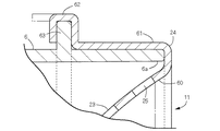
図6に示すように、吸込みグリル11の装着部24は、通気スクリーン23の周縁の内係合壁60と、内係合壁60に連続してL字状に屈曲する外係合壁61で多重筒状に構成する。装着部24をファンケース6の入口6aに装着した状態においては、外係合壁61がファンケース6の外周面に係合している。 As shown in FIG. 6, the mounting portion 24 of the suction grill 11 includes an inner engagement wall 60 on the periphery of the ventilation screen 23 and an outer engagement wall 61 that is bent in an L-shape continuously from the inner engagement wall 60. It is configured as a multiple cylinder. When the mounting portion 24 is mounted on the inlet 6 a of the fan case 6, the outer engagement wall 61 is engaged with the outer peripheral surface of the fan case 6.

外係合壁61の複数個所に係合爪62を一体に設け、係合爪62に対応する係合リブ63をファンケース6の外周面に突設する。装着部24をファンケース6の入口6aに装着した状態において、係合爪62と係合リブ63が係合して、吸込みグリル11をファンケース6に相対移動不能に固定する。 Engaging claws 62 are integrally provided at a plurality of locations on the outer engaging wall 61, and engaging ribs 63 corresponding to the engaging claws 62 are provided on the outer peripheral surface of the fan case 6 so as to project. In a state where the mounting portion 24 is mounted on the inlet 6a of the fan case 6, the engaging claws 62 and the engaging ribs 63 engage with each other to fix the suction grill 11 to the fan case 6 so as not to move relative to each other.

吸込みグリル11の通気スクリーン23は、送風ファン4へ向かって内凹み湾曲状に膨出させる。 The ventilation screen 23 of the suction grill 11 is bulged toward the blower fan 4 in an inwardly curved shape.

図11に示すように、吸込みグリル11の湾曲頂部40と送風ファン4のファンボス4bの対向間隔をaとし、吸込みグリル11の装着部24から通気スクリーン23の湾曲頂部40までの前後距離をbとするとき、対向間隔aと前後距離bが不等式(a<b)を満足するように、吸込みグリル11を配置する。 As shown in FIG. 11, the facing distance between the curved top 40 of the suction grill 11 and the fan boss 4b of the blower fan 4 is a, and the front-back distance from the mounting portion 24 of the suction grill 11 to the curved top 40 of the ventilation screen 23 is b. In this case, the suction grill 11 is arranged such that the facing distance a and the front-rear distance b satisfy the inequality (a<b).

本体ケース1の後部開口9に、吸込口29を備えた吸気体12を装着する。吸気体12は、吸込口29から流入した空気を通気スクリーン23へ向かって案内する筒壁32を備えている。吸込みグリル11の装着部24は、吸気体12の筒前端より前方に位置させる。 An air intake body 12 having a suction port 29 is attached to the rear opening 9 of the main body case 1. The air intake body 12 includes a cylindrical wall 32 that guides the air flowing in from the suction port 29 toward the ventilation screen 23. The mounting portion 24 of the suction grill 11 is located in front of the front end of the cylinder of the air intake body 12.

吸込みグリル11の装着部24から通気スクリーン23の湾曲頂部40までの前後距離をbとし、吸気体12の吸込口29の開口面から吸込みグリル11の通気穴25までの前後距離をeとするとき、前後距離bと前後距離eが不等式(b<e)を満足するように、吸込みグリル11を配置する。 When the front-rear distance from the mounting portion 24 of the suction grill 11 to the curved top portion 40 of the ventilation screen 23 is b, and the front-rear distance from the opening surface of the suction port 29 of the air intake body 12 to the ventilation hole 25 of the suction grill 11 is e. , The suction grille 11 is arranged so that the front-rear distance b and the front-rear distance e satisfy the inequality (b<e).

吸気体12の吸込口29の開口面から、吸込みグリル11の装着部24までの前後距離をdとし、吸込みグリル11の装着部24と送風ファン4のファンブレード4aの対向間隔をcとするとき、前後距離dと対向間隔cが不等式(c<d)を満足するように、吸込みグリル11を配置する。 When the front-rear distance from the opening surface of the suction port 29 of the air intake body 12 to the mounting portion 24 of the suction grill 11 is d, and the facing distance between the mounting portion 24 of the suction grill 11 and the fan blade 4a of the blower fan 4 is c. , The suction grille 11 is arranged so that the front-rear distance d and the facing distance c satisfy the inequality (c<d).

吸気体12の筒後端に吸込口29を設け、筒前端に送出口31を設ける。吸気体12の吸込口29の開口面積をCとし、送出口31の開口面積をDとするとき、開口面積Cと開口面積Dが不等式(C<D)を満足するように設定する。 A suction port 29 is provided at the rear end of the cylinder of the air intake body 12, and a delivery port 31 is provided at the front end of the cylinder. When the opening area of the suction port 29 of the intake body 12 is C and the opening area of the delivery port 31 is D, the opening area C and the opening area D are set so as to satisfy the inequality (C<D).

吸気体12の吸込口29および送出口31のそれぞれを筒状に形成して、両者29・31の間を断面がなだらかに湾曲する拡開筒壁32で連続させる(図1参照)。 Each of the suction port 29 and the delivery port 31 of the air intake body 12 is formed in a tubular shape, and a space between the two 29 and 31 is made continuous by an expanding tubular wall 32 having a gently curved cross section (see FIG. 1).

吸気体12の吸込口29に面して、第1フィルター47を兼ねる整流スクリーン30を配置する。 A rectifying screen 30 that also serves as the first filter 47 is arranged facing the suction port 29 of the air intake body 12.

図3に示すように、整流スクリーン30は、同心円状に配置した複数の整流リブ56と、複数の整流リブ56を支持する交差リブ57で構成する。 As shown in FIG. 3, the rectifying screen 30 includes a plurality of concentric rectifying ribs 56 and cross ribs 57 that support the plurality of rectifying ribs 56.

吸気体12を本体ケース1の後部開口9に装着した状態において、送出口31の筒前端はファンケース6と協同して吸込みグリル11の装着部24を挟持する。 When the air intake body 12 is attached to the rear opening 9 of the main body case 1, the cylinder front end of the delivery port 31 cooperates with the fan case 6 to clamp the attachment portion 24 of the suction grille 11.

図5に示すように、吸込みグリル11の通気スクリーン23の厚みTは、整流リブ56の通気方向のリブ長さL1より小さく設定する。 As shown in FIG. 5, the thickness T of the ventilation screen 23 of the suction grill 11 is set to be smaller than the rib length L1 of the flow regulating ribs 56 in the ventilation direction.

整流リブ56のリブ厚みL2は、整流リブ56の通気方向のリブ長さL1より小さく設定する。 The rib thickness L2 of the flow regulating rib 56 is set to be smaller than the rib length L1 of the flow regulating rib 56 in the ventilation direction.

整流スクリーン30の吸込みグリル11との対向面の側に、第1フィルター47より小さな通気穴48aの一群を備えたメッシュ構造の第2フィルター48を配置する。 A second filter 48 having a mesh structure having a group of ventilation holes 48 a smaller than the first filter 47 is arranged on the side of the rectifying screen 30 facing the suction grill 11.

第2フィルター48は屈曲自在なシート状の軟質材で形成し、整流スクリーン30は第2フィルター48より硬質の素材で形成する。第2フィルター48と整流スクリーン30は隣接配置する。 The second filter 48 is formed of a flexible sheet-shaped soft material, and the rectifying screen 30 is formed of a material harder than the second filter 48. The second filter 48 and the rectifying screen 30 are arranged adjacent to each other.

吸気体12は、筒壁32を備えた前筒45と、吸込口29を備えた後筒46で構成する。第2フィルター48の周縁を前筒45と後筒46で挟持する。 The intake body 12 includes a front cylinder 45 having a cylinder wall 32 and a rear cylinder 46 having a suction port 29. The peripheral edge of the second filter 48 is sandwiched between the front cylinder 45 and the rear cylinder 46.

後筒46と隣接する前筒45の筒端面51に、中央受枠49と、同枠49を支持する支持枠50を、筒端面51と面一になる状態で設ける。第2フィルター48は、筒端面51と中央受枠49と支持枠50に固定する。 A center receiving frame 49 and a support frame 50 for supporting the same frame 49 are provided on the cylinder end surface 51 of the front cylinder 45 adjacent to the rear cylinder 46 so as to be flush with the cylinder end surface 51. The second filter 48 is fixed to the cylinder end surface 51, the central receiving frame 49, and the support frame 50.

前筒45の筒端面51の周囲に、第2フィルター48の周縁を覆う筒壁69を備えた押えリング68を配置する。後筒46は、本体ケース1の後部開口9に装着する。後筒46を後部開口9に装着した状態において、前筒45の筒端面51の周囲に装着した押えリング68を、後筒46で前筒45に向かって押付け固定する。 A holding ring 68 having a cylinder wall 69 that covers the peripheral edge of the second filter 48 is arranged around the cylinder end surface 51 of the front cylinder 45. The rear cylinder 46 is attached to the rear opening 9 of the main body case 1. With the rear cylinder 46 mounted in the rear opening 9, the pressing ring 68 mounted around the cylinder end surface 51 of the front cylinder 45 is pressed and fixed by the rear cylinder 46 toward the front cylinder 45.

後筒46を後部開口9に装着した状態において、第2フィルター48の前後両面を、中央受枠49および支持枠50と整流スクリーン30で挟持する。 With the rear cylinder 46 attached to the rear opening 9, the front and rear surfaces of the second filter 48 are sandwiched between the central receiving frame 49, the support frame 50 and the rectifying screen 30.

後筒46を後部開口9に装着した状態において、第2フィルター48と後筒46の筒前端との間に隙間Eを確保する。 With the rear cylinder 46 attached to the rear opening 9, a gap E is secured between the second filter 48 and the cylinder front end of the rear cylinder 46.

本体ケース1とファンケース6の間に形成される隙間空間に、送風装置の運転状態を制御する制御基板90・91を配置する。 Control boards 90 and 91 for controlling the operating state of the blower are arranged in a clearance space formed between the main body case 1 and the fan case 6.

送風ファン4は、ファンボス4bの周囲に複数のファンブレード4aを配置して構成する。ファンブレード4aの回転方向下手側のブレード前縁と、ファンブレード4aの回転方向上手側のブレード後縁のそれぞれに、ファン騒音を軽減する前凹凸縁85と後凹凸縁86を形成する。 The blower fan 4 is configured by disposing a plurality of fan blades 4a around the fan boss 4b. A front concave-convex edge 85 and a rear concave-convex edge 86 for reducing fan noise are formed on each of the blade leading edge on the lower side in the rotation direction of the fan blade 4a and the blade trailing edge on the upper side in the rotation direction of the fan blade 4a.

前凹凸縁85の凹部85aの隣接ピッチP1を、後凹凸縁86の凹部86aの隣接ピッチP2より大きく設定する。 The adjacent pitch P1 of the concave portions 85a of the front concave-convex edge 85 is set to be larger than the adjacent pitch P2 of the concave portions 86a of the rear concave-convex edge 86.

前凹凸縁85の凹凸深さj1を、後凹凸縁86の凹凸深さj2より小さく設定する。 The uneven depth j1 of the front uneven edge 85 is set to be smaller than the uneven depth j2 of the rear uneven edge 86.

前凹凸縁85の凹部85aと、後凹凸縁86の凹部86aのそれぞれを、湾曲縁で形成する。前凹凸縁85の凹部85aの湾曲半径k1を、後凹凸縁86の凹部86aの湾曲半径k2より大きく設定する。 Each of the concave portion 85a of the front concave-convex edge 85 and the concave portion 86a of the rear concave-convex edge 86 is formed by a curved edge. The curvature radius k1 of the concave portion 85a of the front concave-convex edge 85 is set to be larger than the curvature radius k2 of the concave portion 86a of the rear concave-convex edge 86.

ファンブレード4aは繊維強化プラスチック材で形成する。 The fan blade 4a is made of a fiber reinforced plastic material.

本発明に係る送風装置においては、ファンケース6の入口6aに吸込みグリル11を配置して、先の入口6aを吸込みグリル11の通気スクリーン23で覆うようにした。また、通気スクリーン23をファンケース6の入口6aから送風ファン4へ向かって膨出させて、ファンケース6内の共鳴空間を減少させ、さらに空気流が滞留して渦流を生じやすい空間が形成されるのを解消できるようにした。従って、吸込みグリルの内部中央に乱流騒音を生じやすい滞留空間が形成されるのを避けられなかった従来装置に比べて、共鳴に伴う騒音の増幅を抑止できるうえ、乱流騒音の発生量を大幅に抑止して、その分だけ全体騒音の騒音レベルを減少し静音化できる送風装置を提供できる。また、通気スクリーン23の周縁に設けた装着部24をファンケース6の入口6aに装着固定するので、ファンケース6が振動しようとするのを通気スクリーン23で抑止して、ファンケース6が振動することに伴う騒音の発生を低下できる。 In the blower according to the present invention, the suction grill 11 is arranged at the inlet 6a of the fan case 6, and the previous inlet 6a is covered with the ventilation screen 23 of the suction grill 11. In addition, the ventilation screen 23 is bulged from the inlet 6a of the fan case 6 toward the blower fan 4 to reduce the resonance space in the fan case 6 and to form a space in which the air flow is likely to stay and generate a swirl. I was able to solve the problem. Therefore, as compared with the conventional device in which it was inevitable to form a stagnant space in the center of the suction grill where turbulent noise is likely to occur, amplification of noise due to resonance can be suppressed and the amount of turbulent noise generated can be reduced. It is possible to provide a blower device that can be significantly suppressed, and the noise level of the overall noise can be reduced accordingly and the noise can be reduced. Further, since the mounting portion 24 provided on the periphery of the ventilation screen 23 is mounted and fixed to the inlet 6a of the fan case 6, the ventilation screen 23 prevents the fan case 6 from vibrating, and the fan case 6 vibrates. It is possible to reduce the generation of noise accompanying this.

内係合壁60と、内係合壁60に連続する外係合壁61で装着部24を多重筒状に構成し、装着部24をファンケース6の入口6aに装着した状態において、外係合壁61がファンケース6の外周面に係合するようにした。詳しくは、外係合壁61をファンケース6に装着した状態において、内係合壁60と外係合壁61がファンケース6の筒壁を内外に挟持するようにした。こうした吸込みグリル11の装着構造によれば、吸込みグリル11をファンケース6に対して径方向へ移動できない状態で固定できるうえ、ケース周面に密着する外係合壁61でファンケース6の構造強度を増強できる。従って、モーター5の振動を受けたファンケース6や吸込みグリル11が独自に振動し、あるいは互いにぶつかり合って振動騒音を発生するのを確実に防止して送風騒音を低下できる。 With the inner engagement wall 60 and the outer engagement wall 61 that is continuous with the inner engagement wall 60, the mounting portion 24 is configured in a multi-cylinder shape, and the mounting portion 24 is mounted on the inlet 6 a of the fan case 6 in an external engagement state. The joint wall 61 is adapted to engage with the outer peripheral surface of the fan case 6. Specifically, in a state where the outer engagement wall 61 is attached to the fan case 6, the inner engagement wall 60 and the outer engagement wall 61 sandwich the cylindrical wall of the fan case 6 inside and outside. According to such a mounting structure of the suction grille 11, the suction grille 11 can be fixed to the fan case 6 in a state in which it cannot be moved in the radial direction, and the structural strength of the fan case 6 can be secured by the outer engagement wall 61 that closely contacts the peripheral surface of the case. Can be increased. Therefore, it is possible to surely prevent the fan case 6 and the suction grill 11 that have been subjected to the vibration of the motor 5 from vibrating independently or colliding with each other to generate the vibration noise, thereby reducing the blowing noise.

装着部24をファンケース6の入口6aに装着した状態において、互いに係合する係合爪62と係合リブ63で、吸込みグリル11をファンケース6に相対移動不能に固定すると、吸込みグリル11をファンケース6に対してさらに強固に固定できる。詳しくは、外係合壁61がファンケース6のケース周面に密着係合することに加えて、係合爪62と係合リブ63が係合することで、吸込みグリル11の通風方向の移動を規制して、装着部24を入口6aの端面に密着固定できる。従って、モーター5の振動を受けたファンケース6や吸込みグリル11が独自に振動し、あるいは互いにぶつかり合って振動騒音を発生するのをさらに確実に防止して送風騒音を低下できる。 In a state where the mounting portion 24 is mounted on the inlet 6a of the fan case 6, when the suction grille 11 is fixed to the fan case 6 so as not to be movable relative to each other by the engaging claws 62 and the engaging ribs 63 which engage with each other, the suction grille 11 is fixed. It can be more firmly fixed to the fan case 6. Specifically, in addition to the outer engagement wall 61 being in close contact with the case peripheral surface of the fan case 6, the engagement claws 62 and the engagement ribs 63 are engaged with each other, whereby the suction grille 11 moves in the ventilation direction. The mounting portion 24 can be tightly fixed to the end surface of the inlet 6a. Therefore, it is possible to further reliably prevent the fan case 6 and the suction grill 11 that are subjected to the vibration of the motor 5 from vibrating independently or colliding with each other to generate vibration noise, thereby reducing the blowing noise.

通気スクリーン23の膨出形状が、送風ファン4へ向かって内凹み湾曲状に形成してあると、通気スクリーン23の断面構造を極力単純化して、通気スクリーン23と送風ファン4の間に共鳴空間が形成され、あるいは渦流を生じやすい空間が形成されるのを効果的に解消できる。また、断面構造を単純化できる分だけ、通気スクリーン23の加工コストを削減して、静音化のためのコストを節約することができる。 If the bulging shape of the ventilation screen 23 is formed in a curved shape that is recessed inward toward the blower fan 4, the cross-sectional structure of the ventilation screen 23 is simplified as much as possible, and a resonance space is created between the ventilation screen 23 and the blower fan 4. It is possible to effectively eliminate the formation of a space or the formation of a space in which a swirl is likely to occur. Further, since the sectional structure can be simplified, the processing cost of the ventilation screen 23 can be reduced and the cost for noise reduction can be saved.

吸込みグリル11の装着部24から湾曲頂部40までの前後距離bを、湾曲頂部40とファンボス4bの対向間隔aより大きく設定すると、通気スクリーン23とファンボス4bの間に、乱流騒音を生じやすい滞留空間が形成されるのを解消しながら、内凹み状の通気スクリーン23の湾曲度合いを大きくすることができる。また、通気スクリーン23の湾曲度合いが大きくなるほど、空気流の流速が大きな領域に臨む通気スクリーン23の周辺部分の面積が増加するので、通気スクリーン23の中央における空気流の通過量を減少できる。従って、通気スクリーン23とファンボス4bの間の空間に空気流が滞留し、渦流が発生するのを防止して乱流騒音が発生するのを確実に防止できる。 When the front-rear distance b from the mounting portion 24 of the suction grille 11 to the curved top 40 is set to be larger than the facing distance a between the curved top 40 and the fan boss 4b, turbulent noise is generated between the ventilation screen 23 and the fan boss 4b. It is possible to increase the degree of curvature of the indented ventilation screen 23 while eliminating the formation of an easily retained space. Further, as the bending degree of the ventilation screen 23 increases, the area of the peripheral portion of the ventilation screen 23 that faces the region where the flow velocity of the air flow is large increases, so that the passage amount of the air flow in the center of the ventilation screen 23 can be reduced. Therefore, it is possible to prevent the air flow from staying in the space between the ventilation screen 23 and the fan boss 4b and generate a vortex flow, thereby reliably preventing turbulent noise.

後部開口9に吸込口29を備えた吸気体12を設け、吸気体12に筒壁32を設けると、吸込口29から流入した空気流が筒壁32に案内されて、吸込みグリル11へと流動する間に整流することができる。従って、吸込みグリル11と吸込口29の間に、乱流騒音を生じやすい滞留空間が形成されるのを解消して騒音量を低減できる。また、送風ファン4で発生した騒音を筒壁32で遮蔽して、吸込口29から放散する騒音量を減少できるので、吸込みグリル11による騒音削減効果と相俟って、全体騒音をさらに効果的に削減して静音化できる。従って、従来の騒音防止構造に比べて低コストで全体騒音を減少し静音化できる送風装置を提供できる。 When the intake body 12 having the suction port 29 is provided in the rear opening 9 and the cylinder wall 32 is provided in the intake body 12, the airflow flowing from the suction port 29 is guided to the cylinder wall 32 and flows to the suction grill 11. Can be rectified in between. Therefore, the amount of noise can be reduced by eliminating the formation of the retention space where turbulent noise is likely to occur between the suction grill 11 and the suction port 29. Further, since the noise generated by the blower fan 4 is shielded by the cylinder wall 32 and the amount of noise radiated from the suction port 29 can be reduced, the noise reduction effect of the suction grill 11 is combined with the overall noise to be further effective. It can be reduced to silent. Therefore, as compared with the conventional noise prevention structure, it is possible to provide an air blower that can reduce the total noise and reduce the noise at low cost.

吸込口29の開口面から通気スクリーン23の通気穴25までの前後距離eが、装着部24から湾曲頂部40までの前後距離bより大きく設定してあると、吸込口29から通気スクリーン23に達する空気流を、吸気体12の筒壁32で整流して、吸気体12の内部における乱流の発生を抑止できる。また、送風ファン4の回転騒音やファンブレード4aのブレード騒音を、筒壁32で減衰することができる。従って、通気スクリーン23による乱流騒音の抑止効果と、筒壁32による騒音減衰効果の相乗効果によって送風装置の全体騒音を低減できる。 If the front-rear distance e from the opening surface of the suction port 29 to the ventilation hole 25 of the ventilation screen 23 is set to be larger than the front-rear distance b from the mounting portion 24 to the curved top 40, it reaches the ventilation screen 23 from the suction port 29. The air flow can be rectified by the cylindrical wall 32 of the intake body 12 to suppress the generation of turbulent flow inside the intake body 12. Further, the rotation noise of the blower fan 4 and the blade noise of the fan blade 4a can be attenuated by the cylindrical wall 32. Therefore, the overall noise of the blower can be reduced by the synergistic effect of suppressing the turbulent noise by the ventilation screen 23 and the noise damping effect by the cylindrical wall 32.

吸込口29の開口面から装着部24までの前後距離dが、装着部24とファンブレード4aの対向間隔cより大きく設定してあると、吸込口29から吸込まれてファンブレード4aのブレード縁に達する空気流を、筒壁32と通気スクリーン23で整流して、吸気体12の内部、および通気スクリーン23に臨むファンケース6の内部における乱流の発生を抑止できる。また、送風ファン4の回転騒音やファンブレード4aのブレード騒音を、通気スクリーン23と筒壁32で減衰することができる。従って、通気スクリーン23による乱流騒音の減少効果に加えて、通気スクリーン23と筒壁32による騒音減衰効果によっても、送風装置の全体騒音をさらに低減できる。 When the front-rear distance d from the opening surface of the suction port 29 to the mounting portion 24 is set to be larger than the facing distance c between the mounting portion 24 and the fan blade 4a, the blade edge of the fan blade 4a is sucked by the suction port 29. The arriving airflow can be rectified by the cylinder wall 32 and the ventilation screen 23 to suppress the generation of turbulence inside the air intake body 12 and inside the fan case 6 facing the ventilation screen 23. Further, the rotation noise of the blower fan 4 and the blade noise of the fan blades 4a can be attenuated by the ventilation screen 23 and the cylindrical wall 32. Therefore, in addition to the effect of reducing the turbulent noise due to the ventilation screen 23, the noise of the ventilation screen 23 and the cylindrical wall 32 can be attenuated, thereby further reducing the overall noise of the blower.

筒壁32の送出口31の開口面積Dが吸込口29の開口面積Cより大きく設定してあると、通気スクリーン23を通過した送風ファン4の回転騒音やファンブレード4aのブレード騒音が、吸込口29の側へ漏出ようとするのを、開口面積が小さな吸込口29で封じ込めて、吸込口29から放出される騒音量を減少し、ヘアードライヤーの全体騒音をさらに小さくできる。 If the opening area D of the air outlet 31 of the cylindrical wall 32 is set to be larger than the opening area C of the air inlet 29, the rotation noise of the blower fan 4 passing through the ventilation screen 23 and the blade noise of the fan blades 4a will be It is possible to reduce the amount of noise emitted from the suction port 29 and further reduce the overall noise of the hair dryer by confining the leak to the side of 29 with the suction port 29 having a small opening area.

吸気体12の吸込口29と送出口31の間を、断面がなだらかに湾曲する拡開筒壁32で連続させると、吸込口29から送出口31に至る間の空気の流れをさらに円滑なものとして、吸込み空気を送風ファン4のファンブレード4aへ効率よく送給できる。従って、送風ファン4から送給される乾燥風の送風量を増強して、ヘアードライヤーの送風能力を向上できる。また、吸込口29から送出口31に至る間の空気の流れを円滑化することにより、拡開筒壁32の内部で渦流が発生するのを確実に防止できる。 When the inlet 29 and the outlet 31 of the air intake body 12 are made continuous with each other by the expanding cylindrical wall 32 whose section is gently curved, the air flow from the inlet 29 to the outlet 31 becomes smoother. As a result, the sucked air can be efficiently fed to the fan blades 4a of the blower fan 4. Therefore, it is possible to enhance the blowing amount of the dry wind fed from the blowing fan 4 and improve the blowing ability of the hair dryer. Further, by smoothing the flow of air from the suction port 29 to the delivery port 31, it is possible to reliably prevent the generation of a vortex inside the expanding cylindrical wall 32.

吸気体12の吸込口29に面して、第1フィルター47を兼ねる整流スクリーン30を配置すると、吸込口29から流入した空気流を整流スクリーン30で整流し、さらに筒壁32で整流できるので、吸気体12による整流効果をさらに向上できる。また、整流スクリーン30は、大きな塵埃や髪などが空気とともに吸い込まれるのを防ぐ第1フィルター47としても機能するので、整流スクリーン30より風下側に配置される機器の汚損を防止して、送風機能が低下するのを防ぐことにも役立つ。 By arranging the rectifying screen 30 that also functions as the first filter 47 facing the suction port 29 of the air intake body 12, the air flow that has flowed in from the suction port 29 can be rectified by the rectification screen 30 and further can be rectified by the cylindrical wall 32. The rectification effect by the intake body 12 can be further improved. Further, since the rectifying screen 30 also functions as the first filter 47 that prevents large dust, hair, and the like from being sucked together with the air, the rectifying screen 30 is prevented from being contaminated by the devices arranged on the leeward side and has a blowing function. It also helps prevent the drop.

同心円状に配置した複数の整流リブ56と、複数の整流リブ56を支持する交差リブ57で構成した整流スクリーン30によれば、吸込口29から流入した空気流が整流スクリーン30を通過するときの騒音の発生量を小さくして静音化に寄与できる。例えば、ハニカム構造の通気面を備えた整流スクリーンの場合には、より高い整流効果が得られるが、空気流がハニカム構造に衝突して発生する騒音が大きいため、送風騒音を減らして静音化するのには不向きである。 According to the rectifying screen 30 composed of the plurality of rectifying ribs 56 arranged concentrically and the crossing ribs 57 supporting the plurality of rectifying ribs 56, when the airflow flowing from the suction port 29 passes through the rectifying screen 30, The amount of noise generated can be reduced to contribute to noise reduction. For example, in the case of a rectifying screen having a ventilation surface of a honeycomb structure, a higher rectifying effect can be obtained, but since the airflow collides with the honeycomb structure and a large amount of noise is generated, the blast noise is reduced and the noise is reduced. Not suitable for.

吸気体12を本体ケース1の後部開口9に装着した状態において、吸込みグリル11の装着部24を、送出口31の筒前端とファンケース6で挟持すると、ファンケース6の装着した吸込みグリル11を、さらに強固に固定できる。 When the mounting portion 24 of the suction grill 11 is sandwiched between the front end of the delivery port 31 and the fan case 6 in a state where the intake body 12 is mounted in the rear opening 9 of the main body case 1, the suction grill 11 mounted in the fan case 6 is , Can be fixed more firmly.

吸込みグリル11の通気スクリーン23の厚みTが、整流リブ56の通気方向のリブ長さL1より小さく設定してあると、吸込口29による整流効果を向上しながら静音効果を高めることができる。 If the thickness T of the ventilation screen 23 of the suction grill 11 is set to be smaller than the rib length L1 of the rectifying rib 56 in the ventilation direction, it is possible to enhance the rectifying effect by the suction port 29 and enhance the silent effect.

整流リブ56のリブ厚みL2が、整流リブ56の通気方向のリブ長さL1より小さく設定してあると、整流効果を確実に発揮しながら、吸込口29が整流リブ56で塞がれて通風抵抗が大きくなるのを防止できるので、送風ファン4による送風効率を向上できる。 If the rib thickness L2 of the rectifying rib 56 is set to be smaller than the rib length L1 of the rectifying rib 56 in the ventilation direction, the suction port 29 is blocked by the rectifying rib 56 while surely exhibiting the rectifying effect. Since the resistance can be prevented from increasing, the blowing efficiency of the blowing fan 4 can be improved.

整流スクリーン30の吸込みグリル11との対向面の側に、第1フィルター47より小さな通気穴48aの一群を備えたメッシュ構造の第2フィルター48を配置すると、小さな塵埃や髪などが吸込みグリル11の側へ吸込まれるのを確実に防止できる。 If a second filter 48 having a mesh structure having a group of ventilation holes 48a smaller than the first filter 47 is arranged on the side of the rectifying screen 30 facing the suction grill 11, small dust, hair, etc. can be removed from the suction grill 11. It can be reliably prevented from being sucked to the side.

シート状の軟質材で第2フィルター48を形成し、整流スクリーン30は第2フィルター48より硬質の素材で形成すると、軟質材からなる第2フィルター48を整流スクリーン30で保護することができる。例えば、第2フィルター48に付着した塵埃などを真空掃除機で吸引除去するような場合に、第2フィルター48が過剰にたわみ変形されて破損するのを整流スクリーン30で防止できる。 If the second filter 48 is made of a sheet-shaped soft material and the rectifying screen 30 is made of a material harder than the second filter 48, the second filter 48 made of a soft material can be protected by the rectifying screen 30. For example, the rectifying screen 30 can prevent the second filter 48 from being excessively bent and deformed to be damaged when dust or the like attached to the second filter 48 is sucked and removed by a vacuum cleaner.

吸込口29を備えた後筒46と、前筒45で吸気体12を構成し、第2フィルター48の周縁を前筒45と後筒46で挟持すると、軟質材で形成した第2フィルター48が外力を受けて吸気体12から分離するのを確実に防止できる。また、前筒45と後筒46を利用して第2フィルター48の周縁を挟持するので、別途フィルター装着構造を設ける必要がなく、その分だけ送風装置のコストを削減できる。 When the rear cylinder 46 having the suction port 29 and the front cylinder 45 constitute the intake body 12 and the peripheral edge of the second filter 48 is sandwiched between the front cylinder 45 and the rear cylinder 46, the second filter 48 formed of a soft material is formed. It is possible to reliably prevent the intake body 12 from being separated by an external force. Further, since the peripheral edge of the second filter 48 is held by using the front cylinder 45 and the rear cylinder 46, it is not necessary to separately provide a filter mounting structure, and the cost of the blower can be reduced accordingly.

第2フィルター48を、前筒45に設けた筒端面51と中央受枠49と支持枠50に固定すると、外部空気が送風ファン4へ向かって吸込まれるとき、第2フィルター48が風圧を受けて通風方向へたわむのを防止して、同フィルター48を適正な状態に保持できる。従って吸込口29から吸込まれた外部空気の、第2フィルター48によるろ過を常に安定した状態で行って、第2フィルター48より下流側の吸込みグリル11や送風ファン4を清浄な状態に保持できる。 When the second filter 48 is fixed to the cylinder end surface 51 provided on the front cylinder 45, the central receiving frame 49, and the support frame 50, when the external air is sucked toward the blower fan 4, the second filter 48 receives wind pressure. The filter 48 can be held in an appropriate state by preventing the filter 48 from being bent in the ventilation direction. Therefore, the external air sucked from the suction port 29 can be constantly filtered by the second filter 48 in a stable state, and the suction grill 11 and the blower fan 4 on the downstream side of the second filter 48 can be kept in a clean state.

前筒45の筒端面51の周囲に押えリング68を装着し、後筒46を後部開口9に装着した状態において、押えリング68を、後筒46で前筒45に向かって押付け固定すると、第2フィルター48の周縁を押えリング68で強固に固定して、第2フィルター48が前筒45から分離するのを確実に防止できる。また、ヘアードライヤーの使用時に、押えリング68が前後方向や径方向へ遊動するのを防止して確りと固定できる。 When the pressing ring 68 is mounted around the cylinder end surface 51 of the front cylinder 45, and the rear cylinder 46 is mounted in the rear opening 9, the pressing ring 68 is pressed and fixed by the rear cylinder 46 toward the front cylinder 45. The peripheral edge of the second filter 48 is firmly fixed by the pressing ring 68, and the second filter 48 can be reliably prevented from separating from the front cylinder 45. Further, when the hair dryer is used, the pressing ring 68 can be prevented from floating in the front-rear direction and the radial direction, and can be firmly fixed.

第2フィルター48の前後面を、中央受枠49および支持枠50と整流スクリーン30の3者で挟持すると、第2フィルター48が前後双方へたわみ変形するのを前記3者で規制して、さらに確りと保持固定できる。従って第2フィルター48に、送風ファン4の送風作用による風圧が作用し、あるいは真空掃除機の真空圧が作用するような場合でも、第2フィルター48が大きくたわみ変形し破損するのを確実に防止できる。 When the front and rear surfaces of the second filter 48 are sandwiched between the central receiving frame 49, the support frame 50, and the rectifying screen 30, the second filter 48 is prevented from flexurally deforming in the front and rear by the three parties, and it is more reliable. Can be held and fixed. Therefore, even when the wind pressure due to the blowing action of the blower fan 4 acts or the vacuum pressure of the vacuum cleaner acts on the second filter 48, the second filter 48 is surely prevented from being greatly deformed and damaged. it can.

後筒46を後部開口9に装着した状態において、第2フィルター48と後筒46の筒前端との間に隙間Eを確保すると、第2フィルター48の周縁が後筒46の筒前端で押圧されるのを避けて、第2フィルター48の周縁にストレスが掛かるのを解消できる。従って、吸込口29を介して目視できる第2フィルター48の周縁部分が早期に破損するのを防止できる。 When the clearance E is secured between the second filter 48 and the cylinder front end of the rear cylinder 46 with the rear cylinder 46 attached to the rear opening 9, the peripheral edge of the second filter 48 is pressed by the cylinder front end of the rear cylinder 46. It is possible to prevent the stress from being applied to the peripheral edge of the second filter 48 by avoiding the stress. Therefore, it is possible to prevent early damage to the peripheral portion of the second filter 48 that is visible through the suction port 29.

本体ケース1とファンケース6の間に形成される隙間空間に、送風装置の運転状態を制御する制御基板90・91が配置してあると、ファンケース6の外の送風騒音が、本体ケース1の外へ放散されるのを制御基板90・91で遮蔽して、送風装置の静音性を向上することができる。 When the control boards 90 and 91 for controlling the operating state of the blower are arranged in the gap space formed between the main body case 1 and the fan case 6, the blowing noise outside the fan case 6 causes the main body case 1 It is possible to improve the quietness of the blower by blocking the radiation outside of the fan by the control boards 90 and 91.

ファンブレード4aのブレード前縁とブレード後縁のそれぞれに、前凹凸縁85と後凹凸縁86が形成してあると、送風ファン4が回転駆動されるときのファン騒音を減少することができる。詳しくは、前凹凸縁85を設けると、ファンブレード4aの加圧面で空気を押出すとき、ブレード前縁に作用する空気の押出し反力を、前凹凸縁85の凹部85aと凸部85bで分散させることができるので、ブレード前縁がブレード厚み方向へ振動し騒音が発生するのを抑止できる。また、気流がブレード前縁の加圧面で押出されるタイミングを、凹部85aと凸部85bでずらして、ブレード前縁の全体が、同時にブレード厚み方向へ振動するのを抑止できる。
同様に、後凹凸縁86を設けると、加圧面側の気流と、負圧面側の気流がブレード後縁で合流するとき、凹部86aでは合流がより早く起こり、凸部86bでは合流が遅く起こるため、両気流の合流が徐々に行われる。その結果、ブレード後縁で発生する後渦流が細分化されて、ブレード後流の速度ロスが小さくなる。従って、ブレード前縁の振動に伴う騒音と、ブレード後流の速度ロスが大きい場合の騒音を同時に抑止して、ファン騒音を低下できる。
When the front concavo-convex edge 85 and the rear concavo-convex edge 86 are formed on each of the blade leading edge and the blade trailing edge of the fan blade 4a, fan noise when the blower fan 4 is rotationally driven can be reduced. Specifically, when the front concave-convex edge 85 is provided, when air is pushed out by the pressure surface of the fan blade 4a, the pushing reaction force of the air acting on the front edge of the fan blade 4a is dispersed by the concave portion 85a and the convex portion 85b of the front concave-convex edge 85. As a result, it is possible to prevent the blade leading edge from vibrating in the blade thickness direction and generating noise. Further, the timing at which the air flow is pushed out by the pressing surface of the blade leading edge is shifted between the concave portion 85a and the convex portion 85b, and it is possible to prevent the entire blade leading edge from vibrating simultaneously in the blade thickness direction.
Similarly, when the rear concave-convex edge 86 is provided, when the airflow on the pressure surface side and the airflow on the suction surface side merge at the blade trailing edge, they merge earlier in the concave portion 86a and slower in the convex portion 86b. , The two air streams merge gradually. As a result, the post-vortex generated at the blade trailing edge is subdivided, and the velocity loss of the blade wake is reduced. Therefore, the noise due to the vibration of the leading edge of the blade and the noise when the velocity loss of the blade rear flow is large can be suppressed at the same time, and the fan noise can be reduced.

前凹凸縁85の凹部85aの隣接ピッチP1を、後凹凸縁86の凹部86aの隣接ピッチP2より大きく設定すると、前凹凸縁85の凸部85bの面積を大きくして、同凸部85bの構造強度を向上できるので、凸部85bがブレード厚み方向へ振動して騒音が発生するのをさらに効果的に抑止できる。 When the adjacent pitch P1 of the concave portions 85a of the front concave-convex edge 85 is set to be larger than the adjacent pitch P2 of the concave portions 86a of the rear concave-convex edge 86, the area of the convex portion 85b of the front concave-convex edge 85 is increased and the structure of the convex portion 85b is increased. Since the strength can be improved, it is possible to more effectively suppress the generation of noise by vibrating the convex portion 85b in the blade thickness direction.

前凹凸縁85の凹凸深さj1を、後凹凸縁86の凹凸深さj2より小さく設定すると、凹凸深さj1が小さい分だけたわみにくくなるので、前凹凸縁85の凸部85bがブレード厚み方向へ振動して騒音が発生するのをさらに効果的に抑止できる。 When the uneven depth j1 of the front uneven edge 85 is set to be smaller than the uneven depth j2 of the rear uneven edge 86, the convex portion 85b of the front uneven edge 85 is less likely to bend because the uneven depth j1 is smaller. It is possible to more effectively suppress the generation of noise by vibrating to.

前凹凸縁85の凹部85aの湾曲半径k1を、後凹凸縁86の凹部86aの湾曲半径k2より大きく設定すると、前凹凸縁85の凸部85bの断面の変化を緩やかなものにして構造強度を向上でき、その分だけ前凹凸縁85の凸部85bがブレード厚み方向へ振動して騒音が発生するのをさらに効果的に抑止できる。 When the curvature radius k1 of the concave portion 85a of the front concave-convex edge 85 is set to be larger than the curvature radius k2 of the concave portion 86a of the rear concave-convex edge 86, the change in the cross section of the convex portion 85b of the front concave-convex edge 85 is made gentle and the structural strength is increased. Therefore, it is possible to further effectively prevent the convex portion 85b of the front concave-convex edge 85 from vibrating in the blade thickness direction and generating noise.

ファンブレード4aを繊維強化プラスチック材で形成すると、ファンブレード4aをプラスチック材のみで形成する場合に比べて、ファンブレード4aの構造強度を向上して振動しにくくして、ファンブレード4aが振動することに基づくファン騒音を低減できる。 When the fan blade 4a is formed of a fiber reinforced plastic material, the structural strength of the fan blade 4a is improved to make it less likely to vibrate and the fan blade 4a vibrates, as compared with the case where the fan blade 4a is formed of a plastic material only. The fan noise based on can be reduced.

本発明に係るヘアードライヤーの送風構造部分の縦断側面図である。It is a vertical side view of the ventilation structure part of the hair dryer which concerns on this invention. ヘアードライヤーの側面図である。It is a side view of a hair dryer. ヘアードライヤーの吸込みグリル側の構成部材を示す分解背面図である。It is a disassembled rear view which shows the structural member by the side of the suction grill of a hair dryer. 吸込みグリルの周辺構造を示す一部破断分解側面図である。It is a partially broken disassembled side view which shows the surrounding structure of a suction grill. 吸気体の詳細構造を示す縦断側面図である。It is a vertical side view which shows the detailed structure of an air intake body. 吸込みグリルの装着構造を示す断面図である。It is sectional drawing which shows the mounting structure of a suction grill. 後筒の装着構造を示す一部破断側面図である。It is a partially broken side view showing a mounting structure of a rear cylinder. 図1におけるA−A線断面図である。It is the sectional view on the AA line in FIG. 送風ファンの背面図である。It is a rear view of a ventilation fan. ファンブレードの詳細構造を示す拡大背面図である。It is an expansion rear view which shows the detailed structure of a fan blade. 送風構造部分の関係寸法を示す説明図である。It is explanatory drawing which shows the related dimension of a ventilation structure part.

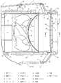
(実施例) 図1ないし図11は、本発明をヘアードライヤー(送風装置)に適用した実施例を示す。本発明における前後、左右、上下とは、図2に示す交差矢印と、矢印の近傍に表記した前後、左右、上下の表示に従う。図2においてヘアードライヤーは、中空筒からなる本体ケース1と、本体ケース1に対して軸2を中心にして折畳み可能に連結したグリップ3を備えている。 (Example) FIGS. 1-11 shows the Example which applied this invention to the hair dryer (blower). The front-rear, left-right, and top-bottom in the present invention follow the cross arrows shown in FIG. In FIG. 2, the hair dryer includes a main body case 1 formed of a hollow cylinder, and a grip 3 that is foldably connected to the main body case 1 about a shaft 2.

図1および図2において本体ケース1は、左右の分割ケース1a・1bと、上ケース1cを接合して中空筒状に構成してあり、その後端に後部開口9が設けられ、前端に吹出口13が設けてある。本体ケース1の内部には乾燥風を送給する軸流型の送風ファン4と、同ファン4を回転駆動するモーター5と、これら両者4・5を支持する丸筒状のファンケース6が配置され、ファンケース6の出口6bに隣接してヒーターユニット7が配置してある。つまり、ファンケース6は、その入口6aと出口6bが、本体ケース1の後部開口9と吹出口13の間に位置する状態で本体ケース1内に配置してある。図1に示すように、ファンケース6の筒壁の下面にはねじボス26が設けてあり、このねじボス26を左側の分割ケース1bにビス27で締結することにより、ファンケース6が本体ケース1に固定してある。左右の分割ケース1a・1bは、図示していないビスで締結固定してある。 1 and 2, the main body case 1 is formed by joining left and right split cases 1a and 1b and an upper case 1c into a hollow cylindrical shape, and a rear opening 9 is provided at a rear end thereof, and a blowout port is provided at a front end thereof. 13 is provided. Inside the main body case 1, there are arranged an axial-flow type blower fan 4 for feeding dry air, a motor 5 for rotationally driving the fan 4, and a round-cylindrical fan case 6 for supporting both of them 4. The heater unit 7 is arranged adjacent to the outlet 6b of the fan case 6. That is, the fan case 6 is arranged in the main body case 1 such that the inlet 6 a and the outlet 6 b thereof are located between the rear opening 9 of the main body case 1 and the air outlet 13. As shown in FIG. 1, a screw boss 26 is provided on the lower surface of the tubular wall of the fan case 6, and the screw boss 26 is fastened to the left split case 1b with a screw 27, so that the fan case 6 is separated from the main body case. It is fixed at 1. The left and right split cases 1a and 1b are fastened and fixed with screws (not shown).

送風ファン4は、4個のファンブレード4aとファンボス4bを一体に備えている。ファンケース6の出口6b側には複数の整流翼15が設けてあり、その中央部分にモーターホルダー16が設けてある。モーター5はホルダー16に装着されており、同ホルダー16の後端から突出する出力軸に送風ファン4が固定してある。つまり、モーター5と送風ファン4は、モーターホルダー16と整流翼15を介してファンケース6で支持されている。送風ファン4で加圧されて捻じられた空気流は、整流翼15で直線的な流れに整流されたのち、ヒーターユニット7へ向かって送給案内される。グリップ3の前面には、モーター5を起動し、あるいはヒーターユニット7への給電状態を切換えるスイッチノブ8が設けてある。また、グリップ3の後面には、モーター5の駆動回転数を変更して送風ファン4の風量を大小に切換える風量切換えノブ10が設けてある。図1において、ファンケース6の入口6aと本体ケース1の後部開口9の間に、ファンケース6の入口6aを覆う吸込みグリル11と、筒状の吸気体12が配置してある。また、本体ケース1の吹出口13には、吹出ノズル14が装着してある(図2参照)。 The blower fan 4 integrally includes four fan blades 4a and a fan boss 4b. A plurality of flow straightening vanes 15 are provided on the outlet 6b side of the fan case 6, and a motor holder 16 is provided at the center thereof. The motor 5 is attached to the holder 16, and the blower fan 4 is fixed to the output shaft protruding from the rear end of the holder 16. That is, the motor 5 and the blower fan 4 are supported by the fan case 6 via the motor holder 16 and the rectifying blades 15. The air flow pressurized and twisted by the blower fan 4 is straightened by the straightening vanes 15 into a linear flow, and then fed toward the heater unit 7. On the front surface of the grip 3, there is provided a switch knob 8 for starting the motor 5 or switching the power supply state to the heater unit 7. Further, on the rear surface of the grip 3, there is provided an air volume switching knob 10 for switching the rotational speed of the motor 5 to switch the air volume of the blower fan 4 between large and small. In FIG. 1, between the inlet 6 a of the fan case 6 and the rear opening 9 of the main body case 1, a suction grill 11 that covers the inlet 6 a of the fan case 6 and a cylindrical air intake body 12 are arranged. An outlet nozzle 14 is attached to the outlet 13 of the main body case 1 (see FIG. 2).

上記のように構成したヘアードライヤーにおいて、送風ファン4が駆動されるときの騒音を大幅に抑止して使用時の全体騒音を減少するために、送風ファン4と後部開口9との間に、吸込みグリル11と吸気体12を記載順に配置している。図3、図4に示すように、吸込みグリル11は、送風ファン4へ向かって膨出する部分球面状(内凹み湾曲状)の通気スクリーン23と、通気スクリーン23の周縁に張出した装着部24を一体に備えている。吸込みグリル11は、アルミニウム板、薄鋼板、ステンレス薄板などを素材とするパンチングメタル状のブランクにプレス加工を施して茶漉し網状に形成してあり、通気スクリーン23には一群の通気穴25が形成してある。この実施例では、通気穴25を通気スクリーン23の内凹み湾曲面の側に限って形成して、通気穴25がフランジ状の装着部24や、内凹み湾曲面と装着部24の境界部分に形成されるのを避けるようにした(図5参照)が、装着部24にも通気穴25が形成してあってもよい。 In the hair dryer configured as described above, in order to significantly suppress the noise when the blower fan 4 is driven and reduce the overall noise when the blower fan 4 is used, suction is performed between the blower fan 4 and the rear opening 9. The grill 11 and the air intake body 12 are arranged in the order described. As shown in FIGS. 3 and 4, the suction grill 11 includes a ventilation screen 23 having a partially spherical shape (inwardly curved concave shape) that bulges toward the blower fan 4, and a mounting portion 24 that extends to the periphery of the ventilation screen 23. It is equipped with. The suction grill 11 is formed by punching a metal-made blank made of an aluminum plate, a thin steel plate, a stainless thin plate, etc., into a tea strainer net-like shape by pressing, and forming a group of ventilation holes 25 in the ventilation screen 23. I am doing it. In this embodiment, the ventilation hole 25 is formed only on the side of the inner concave curved surface of the ventilation screen 23, and the ventilation hole 25 is formed in the flange-shaped mounting portion 24 or the boundary portion between the inner concave curved surface and the mounting portion 24. Although the formation is avoided (see FIG. 5 ), the mounting portion 24 may be provided with the ventilation hole 25.

吸気体12は、それぞれプラスチック成型品からなる前筒45と後筒46で構成されており、後筒46に吸込口29が設けてある。また、吸込口29に臨む前筒45と後筒46の隣接部分には、第1フィルター47を兼ねる整流スクリーン30と、第2フィルター48が配置してある。前筒45は前後が開口する丸筒体からなり、その筒壁の直径はファンケース6へ向かって徐々に大きく設定してあり、入口から送出口(出口)31にわたる筒壁がなだらかに湾曲する拡開筒壁(筒壁)32として構成してある。 The air intake body 12 is composed of a front cylinder 45 and a rear cylinder 46 each made of a plastic molded product, and the rear cylinder 46 is provided with a suction port 29. Further, a rectifying screen 30 also serving as the first filter 47 and a second filter 48 are arranged in the adjacent portion of the front cylinder 45 and the rear cylinder 46 facing the suction port 29. The front cylinder 45 is composed of a round cylinder whose front and rear are open, and the diameter of the cylinder wall is set to be gradually larger toward the fan case 6, and the cylinder wall extending from the inlet to the outlet (outlet) 31 is gently curved. It is configured as an expanded cylindrical wall (cylindrical wall) 32.

前筒45の後筒46との隣接部には、第2フィルター48を受止める枠構造が設けてある。図3に示すように枠構造は、円形の中央受枠49と、同枠49を支持するX字状の支持枠50からなり、中央受枠49および支持枠50は、前筒45の筒端面51と面一に設けてある。吸気体12は、前筒45による整流効果で乱流騒音を減少する機能と、整流スクリーン30および第2フィルター48による、髪や塵埃などがファンケース6内へ吸込まれるのを防止する機能を同時に発揮する。なお、整流スクリーン30は、整流効果を発揮できることが好ましいが、単に毛髪や指の侵入を防止できる防護構造であってもよい。 A frame structure for receiving the second filter 48 is provided adjacent to the rear cylinder 46 of the front cylinder 45. As shown in FIG. 3, the frame structure includes a circular center receiving frame 49 and an X-shaped support frame 50 that supports the frame 49. The center receiving frame 49 and the support frame 50 are the end face 51 of the front cylinder 45 and the cylinder end face 51. It is provided flush. The air intake body 12 has a function of reducing turbulent noise by the rectification effect of the front cylinder 45 and a function of preventing hair, dust, and the like from being sucked into the fan case 6 by the rectification screen 30 and the second filter 48. Demonstrate at the same time. The rectifying screen 30 preferably has a rectifying effect, but may have a protective structure that can simply prevent invasion of hair or fingers.

第2フィルター48は、屈曲自在なシート状の軟質材で形成してある。より詳しくは、細いプラスチック線材を交差させた市販の樹脂メッシュで形成してあり、第1フィルター47に比べて充分に小さな通気穴48aの一群を備えていて、髪の毛や小さな塵埃がファンケース6の内部に入込むのを阻止する。図5に示すように、第2フィルター48は浅い皿状に加熱成形されており、その端面を中央受枠49と支持枠50と筒端面51に熱溶着することで前筒45と一体化してある。吸気体12を本体ケース1の後部開口9に装着した状態では、第2フィルター48の前後面が、プラスチック製の中央受枠49および支持枠50と整流スクリーン30で確りと挟持される。つまり、屈曲自在なシート状の軟質材で形成した第2フィルター48が、同フィルター48より硬質の中央受枠49および支持枠50と整流スクリーン30で確りと挟持されることになる。従って第2フィルター48に、送風ファン4の送風作用による風圧が作用し、あるいは真空掃除機の真空圧が作用するような場合でも、第2フィルター48が大きくたわみ変形し破損するのを防止できる。 The second filter 48 is formed of a flexible sheet-shaped soft material. More specifically, it is formed of a commercially available resin mesh in which thin plastic wires are crossed, and it has a group of ventilation holes 48a that are sufficiently smaller than the first filter 47, so that hair and small dust can be removed from the fan case 6. Prevent it from getting inside. As shown in FIG. 5, the second filter 48 is heat-molded into a shallow dish shape, and its end face is heat-welded to the central receiving frame 49, the support frame 50, and the cylinder end face 51 to be integrated with the front cylinder 45. .. When the air intake body 12 is attached to the rear opening 9 of the main body case 1, the front and rear surfaces of the second filter 48 are firmly sandwiched between the central receiving frame 49 and the supporting frame 50 made of plastic and the rectifying screen 30. That is, the second filter 48 formed of a flexible sheet-shaped soft material is securely sandwiched between the center receiving frame 49 and the support frame 50, which are harder than the filter 48, and the rectifying screen 30. Therefore, even when the wind pressure due to the blowing action of the blower fan 4 acts or the vacuum pressure of the vacuum cleaner acts on the second filter 48, it is possible to prevent the second filter 48 from being greatly deformed and damaged.

図7に示すように後筒46は、2重筒状の筒主部53と、筒主部53の上下に張出されるカバー壁54・55を一体に備えており、筒主部53の内側の壁がベルマウス状の吸込口29になっている。このように、吸込口29をベルマウス状に形成することにより、吸気体12内へ吸込まれる空気の流れをスムースなものとして静音効果を高めることができる。吸込口29と先の拡開筒壁32は滑らかに連続して、両者の断面が緩やかなS字状を呈している。後筒46の前筒45との隣接端に先の整流スクリーン30が一体に形成してある。図3に示すように整流スクリーン30は、同心円状に配置した4重丸状の整流リブ56と、各整流リブ56を支持するX字状の交差リブ57で構成してある。 As shown in FIG. 7, the rear cylinder 46 integrally includes a double cylinder-shaped cylinder main portion 53 and cover walls 54 and 55 extending above and below the cylinder main portion 53. Has a bell mouth-shaped suction port 29. As described above, by forming the suction port 29 in a bell mouth shape, the flow of the air sucked into the air intake body 12 can be made smooth and the silent effect can be enhanced. The suction port 29 and the expanding cylindrical wall 32 are smoothly continuous with each other and have a gentle S-shaped cross section. The straightening screen 30 is integrally formed at the end of the rear cylinder 46 adjacent to the front cylinder 45. As shown in FIG. 3, the rectifying screen 30 is composed of quadruple round rectifying ribs 56 arranged concentrically and X-shaped crossing ribs 57 that support each rectifying rib 56.

吸込口29による整流効果を向上しながら静音効果を高めるために、図5に示すように、吸込みグリル11の通気スクリーン23の厚みTを、整流リブ56の通気方向のリブ長さL1より小さく設定している。また、整流効果を確実に発揮できるようにしながら、吸込口29が塞がれて通風抵抗が大きくなるのを防ぐために、整流リブ56のリブ厚みL2を、整流リブ56の通気方向のリブ長さL1より小さく設定している。 In order to improve the noise reduction effect while improving the rectification effect by the suction port 29, as shown in FIG. 5, the thickness T of the ventilation screen 23 of the suction grille 11 is set smaller than the rib length L1 of the rectification rib 56 in the ventilation direction. doing. In addition, the rib thickness L2 of the rectifying rib 56 is set to the length of the rectifying rib 56 in the ventilation direction in order to prevent the suction port 29 from being blocked and the ventilation resistance from increasing while ensuring the rectifying effect. It is set smaller than L1.

次に、吸込みグリル11のファンケース6に対する固定構造と、前筒45とファンケース6の連結構造と、前筒45と後筒46の連結構造と、後筒46の後部開口9に対する装着構造などを説明する。
図5および図6に示すように、吸込みグリル11の装着部24は、通気スクリーン23の周縁の内係合壁60と、内係合壁60に連続してL字状に屈曲する外係合壁61で多重筒状に形成してある。また、外係合壁61の周囲4個所には係合爪62が一体に設けてあり、ファンケース6の外周面には、係合爪62を係合するための係合リブ63が周回状に突設してある。外係合壁61をファンケース6の入口6aの周面に外嵌し、さらに係合爪62を係合リブ63に係合することにより、吸込みグリル11をファンケース6に対して分離不能に、しかも相対移動不能に一体化できる。この状態の内係合壁60と外係合壁61はファンケース6の筒壁を内外に挟持しているので、吸込みグリル11をファンケース6に対して径方向へ移動できない状態で固定できるうえ、ケース周面に密着する外係合壁61でファンケース6の構造強度を増強して、モーター5の振動を受けたファンケース6が振動騒音を発生するのを抑止できる。図6に示すように、係合爪62は、外係合壁61をファンケース6に装着したのち、爪先端を折曲げて係合リブ63に係合する。
Next, a structure for fixing the suction grille 11 to the fan case 6, a connecting structure for the front cylinder 45 and the fan case 6, a connecting structure for the front cylinder 45 and the rear cylinder 46, a mounting structure for the rear opening 9 of the rear cylinder 46, and the like. Will be explained.
As shown in FIGS. 5 and 6, the mounting portion 24 of the suction grille 11 includes an inner engagement wall 60 at the peripheral edge of the ventilation screen 23 and an outer engagement that is bent in an L-shape continuously from the inner engagement wall 60. The wall 61 is formed in a multi-cylinder shape. Further, engaging claws 62 are integrally provided at four locations around the outer engaging wall 61, and engaging ribs 63 for engaging the engaging claws 62 are formed in a circular shape on the outer peripheral surface of the fan case 6. It is protruding. By fitting the outer engaging wall 61 onto the peripheral surface of the inlet 6a of the fan case 6 and engaging the engaging claws 62 with the engaging ribs 63, the suction grill 11 cannot be separated from the fan case 6. Moreover, they can be integrated so that they cannot move relative to each other. Since the inner engagement wall 60 and the outer engagement wall 61 in this state sandwich the tubular wall of the fan case 6 inside and outside, the suction grill 11 can be fixed to the fan case 6 in a state in which it cannot move in the radial direction. The structural strength of the fan case 6 can be enhanced by the outer engagement wall 61 that is in close contact with the peripheral surface of the case, and the fan case 6 that receives the vibration of the motor 5 can be prevented from generating vibration noise. As shown in FIG. 6, after the outer engagement wall 61 is attached to the fan case 6, the engagement claw 62 is bent at the tip of the claw to engage with the engagement rib 63.

図4に示すように、前筒45のファンケース6との隣接部の周面には、四角形状の4個の連結爪64が前向きに突設されて、各連結爪64の壁面に四角形の連結穴65が形成してある。また、ファンケース6の周面の4個所には、連結穴65と係合する連結突起66が形成してある。吸込みグリル11の装着部24をファンケース6に装着したのち、前筒45の連結爪64をファンケース6の周面にあてがい、その連結穴65を連結突起66に圧嵌係合することにより、前筒45をファンケース6に固定できる。この装着状態において、前筒45の送出口31の筒端面がファンケース6と協同して、吸込みグリル11の装着部24を挟持固定するので、吸込みグリル11をさらに強固に固定できる。以上の説明から理解できるように、吸込みグリル11と前筒45は、ファンケース6に対して分離不能に固定してある。 As shown in FIG. 4, four quadrangular connecting claws 64 are provided so as to project forward on the peripheral surface of the front cylinder 45 adjacent to the fan case 6. A connection hole 65 is formed. Further, connecting protrusions 66 that engage with the connecting holes 65 are formed at four locations on the peripheral surface of the fan case 6. After the mounting portion 24 of the suction grill 11 is mounted on the fan case 6, the connecting claw 64 of the front cylinder 45 is applied to the peripheral surface of the fan case 6, and the connecting hole 65 is press-fitted and engaged with the connecting protrusion 66. The front cylinder 45 can be fixed to the fan case 6. In this mounted state, the cylinder end surface of the delivery port 31 of the front cylinder 45 cooperates with the fan case 6 to clamp and fix the mounting portion 24 of the suction grill 11, so that the suction grill 11 can be further firmly fixed. As can be understood from the above description, the suction grill 11 and the front cylinder 45 are fixed to the fan case 6 inseparably.

図5に示すように、前筒45と後筒46の隣接部分には押えリング68が設けてある。押えリング68は、第2フィルター48の周縁を覆う筒壁69と、後筒46の吸込口29の前端を受止める連結座70を一体に備えている。押えリング68を前筒45に対して仮固定するために、筒壁69の4か所に係合穴71を形成し、係合穴71に対応するリブ72を前筒45の周面に設けている。押えリング68を前筒45に外嵌装着して、リブ72を係合穴71に落込み係合することにより、押えリング68を前筒45に仮固定できる。この状態で、後筒46を本体ケース1の後部開口9に装着することにより、押えリング68が後筒46で前筒45に向かって押付け固定される。そのため、ヘアードライヤーの使用時に、押えリング68が前後方向や径方向へ遊動するのを防止して確りと固定できる。また、前筒45に固定した第2フィルター48を押えリング68で強固に固定して、第2フィルター48が前筒45から分離するのを確実に防止できる。 As shown in FIG. 5, a pressing ring 68 is provided in the adjacent portion of the front cylinder 45 and the rear cylinder 46. The pressing ring 68 integrally includes a cylindrical wall 69 that covers the peripheral edge of the second filter 48 and a connecting seat 70 that receives the front end of the suction port 29 of the rear cylinder 46. In order to temporarily fix the pressing ring 68 to the front cylinder 45, engagement holes 71 are formed at four positions on the cylinder wall 69, and ribs 72 corresponding to the engagement holes 71 are provided on the peripheral surface of the front cylinder 45. ing. The pressing ring 68 can be temporarily fixed to the front cylinder 45 by externally fitting the pressing ring 68 to the front cylinder 45 and dropping the ribs 72 into the engagement holes 71 to engage them. In this state, by mounting the rear cylinder 46 in the rear opening 9 of the main body case 1, the pressing ring 68 is pressed and fixed by the rear cylinder 46 toward the front cylinder 45. Therefore, when the hair dryer is used, the pressing ring 68 can be prevented from floating in the front-rear direction and the radial direction, and can be firmly fixed. Further, the second filter 48 fixed to the front cylinder 45 can be firmly fixed by the pressing ring 68, and the second filter 48 can be reliably prevented from separating from the front cylinder 45.

押えリング68を後筒46で押付け固定した状態では、第2フィルター48と後筒46の筒前端の間に隙間Eが確保される。このように、第2フィルター48と後筒46の間に隙間Eが形成してあると、押えリング68が筒端面51に押付け固定された状態であっても、第2フィルター48の周縁が後筒46の筒端で押圧されるのを避けて、第2フィルター48の周縁にストレスが掛かるのを解消できる。従って、吸込口29を介して目視できる第2フィルター48の周縁部分が早期に破損するのを防止できる。 When the pressing ring 68 is pressed and fixed by the rear cylinder 46, a gap E is secured between the second filter 48 and the cylinder front end of the rear cylinder 46. In this way, when the gap E is formed between the second filter 48 and the rear cylinder 46, even if the pressing ring 68 is pressed and fixed to the cylinder end surface 51, the peripheral edge of the second filter 48 is rearward. It is possible to avoid being pressed by the tube end of the tube 46 and to prevent stress from being applied to the peripheral edge of the second filter 48. Therefore, it is possible to prevent early damage to the peripheral portion of the second filter 48 that is visible through the suction port 29.

図7に示すように、後筒46を後部開口9に着脱可能に装着するために、後筒46の筒主部53および上下のカバー壁54・55に、三者53〜55の周縁に沿って位置決めリブ74が形成してある。また、上側のカバー壁54の上端の左右中央には掛止爪75が、下側のカバー壁55の下端の左右中央には締結片76がそれぞれ形成してある。さらに筒主部53の上下中央に左右一対の係合爪77が形成してある。後部開口9の側では、その周縁に沿って位置決めリブ74に対応する位置決め溝78が形成され、上ケース1cの左右中央に掛止爪75を係合するための掛止溝79が形成され、左側の分割ケース1aの下端にビス座80が形成してある。さらに、係合爪77に対応する係合段部81が左右の分割ケース1a・1bの上下中央に形成してある。 As shown in FIG. 7, in order to detachably mount the rear cylinder 46 in the rear opening 9, the main cylinder portion 53 of the rear cylinder 46 and the upper and lower cover walls 54 and 55 are provided along the periphery of the tripartites 53 to 55. Positioning ribs 74 are formed. Further, a latching claw 75 is formed at the left-right center of the upper end of the upper cover wall 54, and a fastening piece 76 is formed at the left-right center of the lower end of the lower cover wall 55. Further, a pair of left and right engaging claws 77 are formed in the center of the cylinder main portion 53 in the vertical direction. On the side of the rear opening 9, a positioning groove 78 corresponding to the positioning rib 74 is formed along the peripheral edge thereof, and a hooking groove 79 for engaging the hooking claw 75 is formed in the left-right center of the upper case 1c, A screw seat 80 is formed at the lower end of the left split case 1a. Further, an engaging stepped portion 81 corresponding to the engaging claw 77 is formed at the vertical center of the left and right split cases 1a and 1b.

掛止爪75を掛止溝79に掛止し、さらに各位置決めリブ74を位置決め溝78に係合しながら、図8に示すように係合爪77を係合段部81に圧嵌係合することにより、後筒46を後部開口9に装着して本体ケース1の後面を塞ぐことができる。この状態では、締結片76が後部開口9の内面に入込んでビス座80と上下に正対しているので、ビス座80に挿通したビス(皿ビス)82を締結片76にねじ込むことにより、後筒46を本体ケース1に固定できる。必要に応じてビス82を緩めて後筒46を後部開口9から取外すことにより、後筒46と押えリング68を水洗い洗浄でき、第2フィルター48に付着している塵埃等を除去できる。上記のように、吸気体12を本体ケース1に装着した状態では、その大半の部分が後部開口9より後側に突出しており、後部開口9は後筒46で塞がれている。また、吸込みグリル11の装着部24は、吸気体12の筒前端より前方に位置している。 As shown in FIG. 8, the engaging claws 75 are engaged with the engaging grooves 79, and the positioning ribs 74 are engaged with the positioning grooves 78. By doing so, the rear cylinder 46 can be attached to the rear opening 9 to close the rear surface of the main body case 1. In this state, the fastening piece 76 is inserted into the inner surface of the rear opening 9 and vertically faces the screw seat 80. Therefore, by screwing the screw (disc screw) 82 inserted into the screw seat 80 into the fastening piece 76, The rear cylinder 46 can be fixed to the main body case 1. By loosening the screws 82 as necessary and removing the rear cylinder 46 from the rear opening 9, the rear cylinder 46 and the pressing ring 68 can be washed and washed, and the dust and the like adhering to the second filter 48 can be removed. As described above, in the state where the air intake body 12 is mounted on the main body case 1, most of the portion projects rearward from the rear opening 9, and the rear opening 9 is closed by the rear cylinder 46. The mounting portion 24 of the suction grill 11 is located in front of the front end of the cylinder of the air intake body 12.

送風ファン4のファンブレード4aによって発生する渦や剥離、あるいはファンブレード4aの振動によるブレード騒音を抑止するために、ファンブレード4aを次のように構成した。図9および図10に示すように、ファンブレード4aの回転方向下手側のブレード前縁に前凹凸縁85を設け、ファンブレード4aの回転方向上手側のブレード後縁に後凹凸縁86を形成した。図9の矢印は、送風ファン4の回転方向である。前凹凸縁85は緩やかに湾曲する凹部85aと凸部85bで形成し、後凹凸縁86は前凹凸縁85より凹凸の個数が多い凹部86aと凸部86bで形成した。また、送風ファン4の全体を繊維強化プラスチック材で形成して、ファンブレード4aの構造強度を向上して振動しにくくした。強化繊維としては、ガラス繊維、カーボン繊維、ボロン繊維、芳香族ポリアミド系樹脂繊維などを適用できる。 The fan blade 4a is configured as follows in order to suppress the blade noise caused by the vortex and separation generated by the fan blade 4a of the blower fan 4 or the vibration of the fan blade 4a. As shown in FIGS. 9 and 10, a front uneven edge 85 is provided on the blade front edge on the lower side in the rotation direction of the fan blade 4a, and a rear uneven edge 86 is formed on the blade rear edge on the upper side in the rotation direction of the fan blade 4a. .. The arrow in FIG. 9 indicates the rotation direction of the blower fan 4. The front concave-convex edge 85 is formed by a concave portion 85a and a convex portion 85b which are gently curved, and the rear concave-convex edge 86 is formed by a concave portion 86a and a convex portion 86b in which the number of concaves and convexes is larger than the front concave-convex edge 85. Further, the entire blower fan 4 is formed of a fiber reinforced plastic material to improve the structural strength of the fan blade 4a and make it difficult to vibrate. As the reinforcing fiber, glass fiber, carbon fiber, boron fiber, aromatic polyamide resin fiber or the like can be applied.

このように、前凹凸縁85が複数の凹部85aと凸部85bで波形に形成してあると、ファンブレード4aの加圧面(整流翼15と正対する側)で空気を押出すとき、ブレード前縁に作用する空気の押出し反力を分散させて、ブレード前縁がブレード厚み方向へ振動し騒音が発生するのを抑止できる。また、気流がブレード前縁の加圧面で押出されるタイミングに、凹部85aと凸部85bでずれが生じるので、ブレード前縁の全体が、同時にブレード厚み方向へ振動するのを抑止できる効果もある。
同様に、後凹凸縁86が複数の凹部86aと凸部86bで形成してあると、加圧面側の気流と、負圧面(吸込みグリル11と正対する側)側の気流がブレード後縁で合流するとき、凹部86aでは合流がより早く起こり、凸部86bでは合流が遅く起こるため、両気流の合流が徐々に行われる。その結果、ブレード後縁で発生する後渦流が細分化されて、ブレード後流の速度ロスが小さくなる。従って、ブレード前縁の振動に伴う騒音と、ブレード後流の速度ロスが大きい場合の騒音を同時に抑止して、ファン騒音を低下できる。
In this way, when the front concave-convex edge 85 is formed in a corrugated shape with the plurality of concave portions 85a and the convex portions 85b, when air is pushed out by the pressure surface of the fan blade 4a (the side facing the straightening vanes 15), the blade front The pushing reaction force of air acting on the edge can be dispersed to prevent the blade leading edge from vibrating in the blade thickness direction and generating noise. Further, since the concave portion 85a and the convex portion 85b are displaced at the timing when the air flow is pushed out by the pressing surface of the blade leading edge, there is also an effect that the entire blade leading edge can be suppressed from vibrating in the blade thickness direction at the same time. ..
Similarly, when the rear concave-convex edge 86 is formed by a plurality of concave portions 86a and convex portions 86b, the air flow on the pressure surface side and the air flow on the negative pressure surface (the side facing the suction grill 11) side merge at the blade trailing edge. At this time, merging occurs earlier in the concave portion 86a, and merging occurs later in the convex portion 86b, so that the two air streams merge gradually. As a result, the post-vortex generated at the blade trailing edge is subdivided, and the velocity loss of the blade wake is reduced. Therefore, the noise due to the vibration of the leading edge of the blade and the noise when the velocity loss of the blade wake is large can be suppressed at the same time, and the fan noise can be reduced.

前凹凸縁85による振動規制効果と、後凹凸縁86による後渦流の細分効果をより確実なものとするために、前凹凸縁85と後凹凸縁86の関係寸法を以下のように設定した。図10に示すように、前凹凸縁85の凹部85aの隣接ピッチP1を、後凹凸縁86の凹部86aの隣接ピッチP2より大きく設定した。また、前凹凸縁85の凹凸深さj1を、後凹凸縁86の凹凸深さj2より小さく設定した。さらに、前凹凸縁85の凹部85aの湾曲半径k1を、後凹凸縁86の凹部86aの湾曲半径k2より大きく設定した。 In order to make the vibration regulation effect by the front concave-convex edge 85 and the sub-vortex subdivision effect by the rear concave-convex edge 86 more reliable, the relational dimensions of the front concave-convex edge 85 and the rear concave-convex edge 86 are set as follows. As shown in FIG. 10, the adjacent pitch P1 of the concave portions 85a of the front concave-convex edge 85 is set to be larger than the adjacent pitch P2 of the concave portions 86a of the rear concave-convex edge 86. Further, the uneven depth j1 of the front uneven edge 85 is set to be smaller than the uneven depth j2 of the rear uneven edge 86. Further, the curvature radius k1 of the recess 85a of the front concave-convex edge 85 is set larger than the curvature radius k2 of the recess 86a of the rear concave-convex edge 86.

前凹凸縁85の凹部85aの隣接ピッチP1を、後凹凸縁86の凹部86aの隣接ピッチP2より大きく設定すると、前凹凸縁85の凸部85bの面積を大きくして、同凸部85bの構造強度を向上できる。これに伴い、凸部85bがブレード厚み方向へ振動して騒音が発生するのをさらに効果的に抑止できる。
前凹凸縁85の凹凸深さj1を、後凹凸縁86の凹凸深さj2より小さく設定すると、凹凸深さj1が小さい分だけたわみにくくなるので、前凹凸縁85の凸部85bがブレード厚み方向へ振動して騒音が発生するのをさらに効果的に抑止できる。また、前凹凸縁85の凹部85aの湾曲半径k1を、後凹凸縁86の凹部86aの湾曲半径k2より大きく設定するのも同様の理由からである。
When the adjacent pitch P1 of the concave portions 85a of the front concave-convex edge 85 is set to be larger than the adjacent pitch P2 of the concave portions 86a of the rear concave-convex edge 86, the area of the convex portion 85b of the front concave-convex edge 85 is increased and the structure of the convex portion 85b is increased. Strength can be improved. Along with this, it is possible to more effectively suppress the generation of noise by vibrating the convex portion 85b in the blade thickness direction.
When the uneven depth j1 of the front uneven edge 85 is set to be smaller than the uneven depth j2 of the rear uneven edge 86, the convex portion 85b of the front uneven edge 85 is less likely to bend because the uneven depth j1 is smaller. It is possible to more effectively suppress the generation of noise by vibrating to. Further, the curvature radius k1 of the concave portion 85a of the front concave-convex edge 85 is set to be larger than the curvature radius k2 of the concave portion 86a of the rear concave-convex edge 86 for the same reason.

上記のように、ファンブレード4aに前凹凸縁85と後凹凸縁86を形成した送風ファン4の送風騒音を測定して、従来構造の送風ファンの送風騒音と比較することにより、送風騒音をどの程度低減できたかを確認した。詳しくは、本体ケースの後端に外突湾曲状の吸込みグリルが装着してある測定用のヘアードライヤーを用意し、前凹凸縁85や後凹凸縁86が形成されていない従来の送風ファンを組込んで送風騒音を測定し、さらに本発明に係る送風ファン4を換装して送風騒音を測定して、両者の送風騒音を比較した。送風騒音を測定するについては、本体ケース1の後端から1m離れた位置に騒音計のマイクロフォンを配置し、両者の回転数を同じにして騒音レベルを計測した。その結果、従来構造の送風ファンを組込んだヘアードライヤーの送風騒音に比べて、本発明に係る送風ファン4を組込んだヘアードライヤーの方が、送風騒音を大幅に削減できることを確認した。 As described above, by measuring the blowing noise of the blower fan 4 in which the front concavo-convex edge 85 and the rear concavo-convex edge 86 are formed on the fan blade 4a and comparing it with the blowing noise of the blowing fan of the conventional structure, It was confirmed whether it could be reduced to some extent. Specifically, prepare a hair dryer for measurement in which a suction grill with a curved outer protrusion is attached to the rear end of the main body case, and assemble a conventional blower fan in which the front uneven edge 85 and the rear uneven edge 86 are not formed. The blowing noise was measured in detail, the blowing fan 4 according to the present invention was replaced, and the blowing noise was measured to compare the blowing noises of both. Regarding the measurement of blast noise, a microphone of a sound level meter was arranged at a position 1 m away from the rear end of the main body case 1, and the rotation speeds of both microphones were the same to measure the noise level. As a result, it was confirmed that the hair dryer incorporating the blower fan 4 according to the present invention can significantly reduce the blower noise as compared with the blower noise of the hair dryer incorporating the blower fan having the conventional structure.

先に説明したように、本体ケース1は左右の分割ケース1a・1bと、上ケース1cを接合して中空筒状に構成してあり、図1に示すように、上ケース1cとファンケース6の間、および左右の分割ケース1a・1bの下部とファンケース6の間には、大きな隙間が形成してある。これらの隙間を利用して、下側の隙間に電源−制御基板(制御基板)90を配置し、上側の隙間に温度制御基板(制御基板)91を配置している。また、温度制御基板91にモード切換えスイッチ92を実装して、このスイッチ92を上ケース1cの上面に設けた押ボタン93で切換え操作できるようにしている。図2に示すように、ヒーターユニット7の上側には、イオン発生用の放電電極94が設けてある。上記のように、本体ケース1とファンケース6の間の隙間空間に、制御基板90・91を配置しておくことにより、ファンケース6の外の送風騒音が、本体ケース1の外へ放散されるのを制御基板90・91で遮蔽して、静音性を向上することができる。 As described above, the main body case 1 is configured by joining the left and right split cases 1a and 1b and the upper case 1c into a hollow cylindrical shape. As shown in FIG. 1, the upper case 1c and the fan case 6 are A large gap is formed between the fan case 6 and the lower part of the left and right divided cases 1a and 1b. Utilizing these gaps, the power supply-control board (control board) 90 is arranged in the lower clearance, and the temperature control board (control board) 91 is arranged in the upper clearance. Further, the mode control switch 92 is mounted on the temperature control board 91 so that the switch 92 can be switched by the push button 93 provided on the upper surface of the upper case 1c. As shown in FIG. 2, a discharge electrode 94 for ion generation is provided above the heater unit 7. As described above, by arranging the control boards 90 and 91 in the gap space between the main body case 1 and the fan case 6, the ventilation noise outside the fan case 6 is dissipated to the outside of the main body case 1. The noise can be improved by shielding the noise with the control boards 90 and 91.

スイッチノブ8をオン操作すると、商用の交流電流を電源−制御基板90に供給して、モーター5、ヒーターユニット7、放電電極94などを作動させるための電流を調整する。また、風量切換えノブ10のオン・オフ信号によって、電源−制御基板90がモーター5の駆動回転数を大小に切換える。押ボタン93を操作してモード切換えスイッチ92をオン操作すると、ヒーターユニット7の発熱量が最大になって、100度Cの温風を吹出口13から送出できる。以下、押ボタン93をオン操作するごとに80度C、60度Cの温風を吹出口13から送出でき、再び押ボタン93をオン操作すると、ヒーターユニット7への通電が遮断されて、常温の乾燥風が吹出口13から送出される。以後、同じ温度制御を繰り返し行う。 When the switch knob 8 is turned on, a commercial alternating current is supplied to the power supply-control board 90 to adjust the current for operating the motor 5, the heater unit 7, the discharge electrode 94 and the like. Further, the power supply/control board 90 switches the driving rotation speed of the motor 5 between large and small in response to an on/off signal of the air volume switching knob 10. When the push button 93 is operated and the mode changeover switch 92 is turned on, the heat generation amount of the heater unit 7 is maximized, and the warm air of 100° C. can be blown out from the air outlet 13. Hereinafter, every time the push button 93 is turned on, hot air of 80° C. and 60° C. can be sent out from the outlet 13, and when the push button 93 is turned on again, the power supply to the heater unit 7 is cut off and the temperature is kept at room temperature. Of dry air is sent out from the outlet 13. After that, the same temperature control is repeated.

以上のように構成したヘアードライヤーによれば、使用時に送風ファン4で吸込口29から吸込まれた空気流は、整流スクリーン30および第2フィルター48と拡開筒壁32を通過する間に整流されて、吸込みグリル11へ向かって流動する。このとき、拡開筒壁32を通過した空気流は、通気スクリーン23によって再び整流されながら送風ファン4に吸込まれるが、吸込まれる空気流の殆どは、ファンブレード4aの回転領域と前後に正対する通気スクリーン23の周辺部分から吸い込まれる。これは、ファンブレード4aの回転領域に臨む部分ほど負圧が大きく、ファンボス4bと前後に正対する部分の負圧は小さいからである。 According to the hair dryer configured as described above, the airflow sucked from the suction port 29 by the blower fan 4 during use is rectified while passing through the rectifying screen 30, the second filter 48, and the expanding cylindrical wall 32. And flows toward the suction grill 11. At this time, the airflow that has passed through the expanding cylindrical wall 32 is sucked into the blower fan 4 while being straightened again by the ventilation screen 23, but most of the sucked airflow is forward and backward with respect to the rotation region of the fan blade 4a. The air is sucked in from the peripheral portion of the ventilation screen 23 that faces it. This is because the negative pressure is higher in the portion of the fan blade 4a facing the rotation region, and the negative pressure is smaller in the portion directly facing the fan boss 4b in the front-rear direction.

しかし、通気スクリーン23の湾曲頂部40とファンボス4bの隣接距離は他のスクリーン部位に比べて充分に小さい。そのため、湾曲頂部40の近傍に達した空気流が、湾曲頂部40とファンボス4bの間に滞留する余地はなく、従って空気流の滞留に伴う渦流の発生を防止して乱流騒音の発生を大幅に低下できる。また、台形状のファンボス4bの斜辺部付近には、ファンブレード4aの回転領域に向かって放射方向へ引きずり込まれる空気の流れ(輻射気流)が形成される。この輻射気流によって、湾曲頂部40とファンボス4bの間の空気がファンブレード4aの回転領域へ円滑に送り込まれることも、ファンボス4bと湾曲頂部40の間に空気流が滞留し、渦流が発生するのを解消することに役立っている。このように、吸込みグリル11は、空気流の滞留に伴って乱流騒音が発生するのを低減するために設けてある。 However, the adjoining distance between the curved top 40 of the ventilation screen 23 and the fan boss 4b is sufficiently smaller than the other screen portions. Therefore, there is no room for the airflow reaching the vicinity of the curved top 40 to stay between the curved top 40 and the fan boss 4b. Therefore, the generation of eddy currents due to the retention of the airflow is prevented and turbulent noise is generated. Can be greatly reduced. Further, near the hypotenuse of the trapezoidal fan boss 4b, a flow of air (radiant airflow) that is dragged in the radial direction toward the rotation region of the fan blade 4a is formed. Due to this radiant airflow, the air between the curved top 40 and the fan boss 4b is smoothly sent to the rotating region of the fan blade 4a, and the air flow stays between the fan boss 4b and the curved top 40 to generate a vortex. It helps to eliminate the problem. As described above, the suction grille 11 is provided to reduce the generation of turbulent noise due to the retention of the air flow.

上記の騒音低減構造に加えて、乱流騒音をさらに効果的に減少するために、実施例に係るヘアードライヤーにおいては、送風ファン4と吸込みグリル11と吸気体12の関係寸法等を以下のように設定した。
図11に示すように、吸込みグリル11の通気スクリーン23の湾曲頂部40と送風ファン4のファンボス4bの対向間隔をaとし、吸込みグリル11の装着部24から通気スクリーン23の湾曲頂部40までの前後距離をbとするとき、対向間隔aと前後距離bが不等式(a<b)を満足するように、吸込みグリル11を配置した。
In addition to the above noise reduction structure, in order to further effectively reduce turbulent noise, in the hair dryer according to the embodiment, the relational dimensions of the blower fan 4, the suction grill 11 and the intake body 12 are as follows. Set to.
As shown in FIG. 11, the facing interval between the curved top 40 of the ventilation screen 23 of the suction grill 11 and the fan boss 4b of the blower fan 4 is set to a, and the distance from the mounting portion 24 of the suction grill 11 to the curved top 40 of the ventilation screen 23 is set to a. When the front-rear distance is b, the suction grill 11 is arranged so that the facing distance a and the front-rear distance b satisfy the inequality (a<b).

上記のように前後距離bを対向間隔aより大きく設定すると、通気スクリーン23とファンボス4bの間に、乱流騒音を生じやすい滞留空間が形成されるのを解消しながら、内凹み状の通気スクリーン23の湾曲度合いを大きくすることができる。また、通気スクリーン23の湾曲度合いが大きくなるほど、空気流の流速が大きな領域に臨む通気スクリーン23の周辺部分の面積が増加するので、通気スクリーン23の中央における空気流の通過量を減少できる。従って、通気スクリーン23とファンボス4bの間の空間に空気流が滞留し、渦流が発生するのを防止して乱流騒音が発生するのを確実に防止できる。こうした理由から、不等式(a<b)を満足するように吸込みグリル11を配置している。 When the front-rear distance b is set to be larger than the facing distance a as described above, the formation of a retention space where turbulent noise is likely to occur between the ventilation screen 23 and the fan boss 4b is eliminated, and the ventilation with an indented shape The degree of curvature of the screen 23 can be increased. Further, as the bending degree of the ventilation screen 23 increases, the area of the peripheral portion of the ventilation screen 23 that faces the region where the flow velocity of the air flow is large increases, so that the passage amount of the air flow in the center of the ventilation screen 23 can be reduced. Therefore, it is possible to prevent the air flow from staying in the space between the ventilation screen 23 and the fan boss 4b and generate a vortex flow, thereby reliably preventing turbulent noise. For this reason, the suction grill 11 is arranged so as to satisfy the inequality (a<b).

因みに、通気スクリーン23の湾曲半径が大きいと湾曲度合いが小さくなり、空気流の流速が大きな領域に臨む通気スクリーン23の周辺部分の面積が小さくなるので、通気スクリーン23の中央における空気流の通過量が増加してしまう。上記の実施例では、前後距離bを対向間隔aの約5倍強として、空気流の流速が大きな領域に臨む通気スクリーン23の周辺部分の面積が、充分に大きくなるようにした。 By the way, when the radius of curvature of the ventilation screen 23 is large, the degree of curvature becomes small, and the area of the peripheral portion of the ventilation screen 23 facing the region where the flow velocity of the air flow is large becomes small. Will increase. In the above embodiment, the front-rear distance b is set to about 5 times the facing distance a so that the area of the peripheral portion of the ventilation screen 23 facing the region where the flow velocity of the air flow is large is sufficiently large.

吸込みグリル11の装着部24から通気スクリーン23の湾曲頂部40までの前後距離をbとし、吸気体12の吸込口29の開口面から吸込みグリル11の通気スクリーン23の通気穴25までの前後距離をeとするとき、前後距離bと前後距離eが不等式(b<e)を満足するように、吸込みグリル11を配置した。 The front-rear distance from the mounting portion 24 of the suction grille 11 to the curved top 40 of the ventilation screen 23 is defined as b, and the front-rear distance from the opening surface of the suction port 29 of the intake body 12 to the ventilation hole 25 of the ventilation screen 23 of the suction grille 11 is defined. The suction grille 11 is arranged so that the front-rear distance b and the front-rear distance e satisfy the inequality (b<e).

上記のように、前後距離eを前後距離bより大きく設定すると、吸込口29から吸込まれて通気スクリーン23に達する空気流を、前筒45および吸込口29と整流スクリーン30で整流して、前筒45の内部における乱流の発生を抑止できる。また、送風ファン4の回転騒音やファンブレード4aのブレード騒音を、拡開筒壁32で減衰することができる。従って、通気スクリーン23による乱流騒音の抑止効果に加えて、前筒46による騒音減衰効果によっても、ヘアードライヤーの全体騒音をできる。 As described above, when the front-rear distance e is set to be larger than the front-rear distance b, the air flow that is sucked from the suction port 29 and reaches the ventilation screen 23 is rectified by the front cylinder 45, the suction port 29, and the rectification screen 30, It is possible to suppress the generation of turbulent flow inside the cylinder 45. Further, the rotation noise of the blower fan 4 and the blade noise of the fan blades 4a can be attenuated by the expanding cylindrical wall 32. Therefore, in addition to the effect of suppressing the turbulent flow noise by the ventilation screen 23, the noise of the hair dryer can be reduced by the noise reduction effect of the front cylinder 46.

吸気体12の吸込口29の開口面から、吸込みグリル11の装着部24までの前後距離をdとし、吸込みグリル11の装着部24と送風ファン4のファンブレード4aの対向間隔をcとするとき、前後距離dと対向間隔cが不等式(c<d)を満足するように、吸込みグリル11を配置した。図11において、符号fは後筒46の吸込口29の後端から吸込みグリル11の装着部24までの前後寸法を示している。 When the front-rear distance from the opening surface of the suction port 29 of the air intake body 12 to the mounting portion 24 of the suction grill 11 is d, and the facing distance between the mounting portion 24 of the suction grill 11 and the fan blade 4a of the blower fan 4 is c. The suction grille 11 is arranged so that the front-rear distance d and the facing distance c satisfy the inequality (c<d). In FIG. 11, reference numeral f indicates the front-rear dimension from the rear end of the suction port 29 of the rear cylinder 46 to the mounting portion 24 of the suction grill 11.

上記のように、前後距離dを対向間隔cより大きく設定すると、吸込口29から吸込まれてファンブレード4aのブレード縁に達する空気流を、整流スクリーン30と前筒45と通気スクリーン23の3者で整流して、吸気体12の内部、および通気スクリーン23に臨むファンケース6の内部における乱流の発生を抑止できる。また、送風ファン4の回転騒音やファンブレード4aのブレード騒音を、通気スクリーン23と吸気体12で減衰することができる。従って、通気スクリーン23による乱流騒音の抑止効果と騒音減衰効果に加えて、吸気体12による騒音減衰効果によっても、ヘアードライヤーの全体騒音を低減できる。 As described above, when the front-rear distance d is set to be larger than the facing distance c, the air flow that is sucked from the suction port 29 and reaches the blade edge of the fan blade 4a is divided into three parts: the straightening screen 30, the front cylinder 45, and the ventilation screen 23. It is possible to suppress the generation of turbulent flow inside the air intake body 12 and inside the fan case 6 facing the ventilation screen 23 by rectifying. Further, the rotation noise of the blower fan 4 and the blade noise of the fan blade 4a can be attenuated by the ventilation screen 23 and the air intake body 12. Therefore, in addition to the effect of suppressing turbulent noise and the noise damping effect of the ventilation screen 23, the noise damping effect of the air intake body 12 can reduce the overall noise of the hair dryer.

吸気体12の吸込口29の開口面積をCとし、送出口31の開口面積をDとするとき、開口面積Cと開口面積Dが不等式(C<D)を満足するように設定した。このように、送出口31の開口面積Dが開口面積Cより大きく設定してあると、通気スクリーン23を通過した送風ファン4の回転騒音やファンブレード4aのブレード騒音が、吸込口29の側へ漏出ようとするのを、開口面積が小さな吸込口29で封じ込めて、吸込口29から放出される騒音量を減少し、ヘアードライヤーの全体騒音をさらに小さくできる。また、送出口31から通気スクリーン23へ流入する直前の空気流の流速を低下させて、通気スクリーン23の通気穴25を通過した後の通過空気流の近傍で渦流が発生するのを抑止し、その分だけヘアードライヤーの全体騒音を小さくできる。 When the opening area of the suction port 29 of the intake body 12 is C and the opening area of the delivery port 31 is D, the opening area C and the opening area D are set to satisfy the inequality (C<D). As described above, when the opening area D of the outlet 31 is set to be larger than the opening area C, the rotation noise of the blower fan 4 and the blade noise of the fan blade 4a that have passed through the ventilation screen 23 are directed toward the suction port 29. It is possible to reduce the amount of noise emitted from the suction port 29 and further reduce the overall noise of the hair dryer by sealing off the leaks with the suction port 29 having a small opening area. Further, the flow velocity of the air flow immediately before flowing into the ventilation screen 23 from the delivery port 31 is reduced to suppress the generation of a vortex near the passing air flow after passing through the ventilation holes 25 of the ventilation screen 23, To that extent, the overall noise of the hair dryer can be reduced.

上記の実施例では、吸気体12の後筒46を本体ケース1に着脱自在に装着したが、その必要はなく、吸気体12は本体ケース1に対して単に固定した状態で装着してあってもよい。吸込みグリル11は金属板で形成する必要はなく、プラスチック成形品で形成することができる。その場合には、係合爪62をフック状に成形しておき、係合リブ63に対して係合爪62を弾性変形させながら係合するとよい。通気スクリーン23は、ひとつの湾曲面からなる内凹み湾曲形状である必要はなく、複数の湾曲面を多段状に重ねた湾曲面で形成することができる。必要があれば、通気スクリーン23の断面が波形に折り曲げられた湾曲面であってもよい。第2フィルター48は中央受枠49および支持枠50と筒端面51に熱溶着する必要はなく、接着剤で接着固定してもよい。 Although the rear cylinder 46 of the air intake body 12 is detachably attached to the main body case 1 in the above embodiment, it is not necessary to attach the rear cylinder 46 to the main body case 1 and the rear cylinder 46 is attached to the main body case 1 only in a fixed state. Good. The suction grill 11 does not need to be formed of a metal plate, but can be formed of a plastic molded product. In that case, the engaging claw 62 may be formed in a hook shape and engaged with the engaging rib 63 while elastically deforming the engaging claw 62. The ventilation screen 23 does not need to have an inwardly curved shape formed of one curved surface, and can be formed by a curved surface formed by stacking a plurality of curved surfaces in a multi-step manner. If necessary, the cross section of the ventilation screen 23 may be a curved surface bent in a corrugated shape. The second filter 48 does not need to be heat-welded to the central receiving frame 49, the support frame 50, and the tube end surface 51, but may be fixed by adhesion with an adhesive.

本発明は、ヘアードライヤー以外に、カールドライヤーやサーキュレーター等の吸込みグリルを備えている送風装置にも広く適用できる。 INDUSTRIAL APPLICABILITY The present invention can be widely applied to a blower equipped with a suction grill such as a curl dryer or a circulator in addition to a hair dryer.

1 本体ケース
4 送風ファン
5 モーター
6 ファンケース
9 後部開口
11 吸込みグリル
12 吸気体
23 11の通気スクリーン
24 11の装着部
25 23の通気穴
29 吸込口
30 整流スクリーン
45 前筒
46 後筒
48 第2フィルター
53 主筒部
54・55 カバー壁
60 内係合壁
61 外係合壁
68 押えリング
85 前凹凸縁
86 後凹凸縁
1 Main Body Case 4 Blower Fan 5 Motor 6 Fan Case 9 Rear Opening 11 Suction Grille 12 Air Intake Body 23 11 Ventilation Screen 24 11 Mounting Part 25 23 Vent Hole 29 Suction Port 30 Rectifying Screen 45 Front Tube 46 Rear Tube 48 Filter 53 Main cylinder part 54/55 Cover wall 60 Inner engagement wall 61 Outer engagement wall 68 Presser ring 85 Front uneven edge 86 Rear uneven edge

Claims (14)

後部開口(9)と吹出口(13)を備えた本体ケース(1)の内部に、モーター(5)および送風ファン(4)を支持し、少なくとも送風ファン(4)の周囲を覆うファンケース(6)が配置してある送風装置であって、
ファンケース(6)は、その入口(6a)と出口(6b)が、本体ケース(1)の後部開口(9)と吹出口(13)の間に位置する状態で本体ケース(1)内に配置されており、
ファンケース(6)の入口(6a)に、該入口(6a)を覆う吸込みグリル(11)が配置されており、
吸込みグリル(11)は、通気スクリーン(23)と、通気スクリーン(23)の周縁に設けた装着部(24)を備えており、
装着部(24)をファンケース(6)の入口(6a)に装着固定した状態において、通気スクリーン(23)が、ファンケース(6)の入口(6a)から送風ファン(4)へ向かって膨出させてあり、
本体ケース(1)の後部開口(9)に、吸込口(29)を備えた吸気体(12)が装着されており、
吸気体(12)は、吸込口(29)から流入した空気を通気スクリーン(23)へ向かって案内する筒壁(32)を備えており、
吸気体(12)の吸込口(29)に面して、第1フィルター(47)を兼ねる整流スクリーン(30)が配置してあることを特徴とする送風装置。
A fan case (which supports a motor (5) and a blower fan (4) inside a main body case (1) having a rear opening (9) and an outlet (13) and covers at least the periphery of the blower fan (4). A blower device in which 6) is arranged,
The fan case (6) is located inside the main body case (1) with its inlet (6a) and outlet (6b) located between the rear opening (9) and the outlet (13) of the main body case (1). Has been placed,
At the inlet (6a) of the fan case (6), a suction grill (11) covering the inlet (6a) is arranged.
The suction grille (11) includes a ventilation screen (23) and a mounting portion (24) provided on the periphery of the ventilation screen (23),
The ventilation screen (23) expands from the inlet (6a) of the fan case (6) toward the blower fan (4) in a state where the mounting portion (24) is mounted and fixed to the inlet (6a) of the fan case (6). Ri Oh so issued,
An air intake body (12) having a suction port (29) is attached to a rear opening (9) of the main body case (1),
The air intake body (12) includes a cylindrical wall (32) for guiding the air flowing in from the suction port (29) toward the ventilation screen (23),
An air blower characterized in that a rectifying screen (30) also serving as a first filter (47) is arranged facing the suction port (29) of the air intake body (12) .
整流スクリーン(30)が、同心円状に配置した複数の整流リブ(56)と、複数の整流リブ(56)を支持する交差リブ(57)で構成してある請求項1に記載の送風装置。 2. The blower device according to claim 1, wherein the straightening screen (30) includes a plurality of concentric straightening ribs (56) and cross ribs (57) supporting the plurality of straightening ribs (56) . 吸気体(12)の吸込口(29)および送出口(31)のそれぞれが筒状に形成されて、両者(29・31)の間を断面がなだらかに湾曲する拡開筒壁(32)で連続させてある請求項1または2に記載の送風装置。 Each of the suction port (29) and the delivery port (31) of the air intake body (12) is formed in a tubular shape, and an expanded tubular wall (32) having a gently curved cross section between the two (29, 31) is formed. The air blower according to claim 1 or 2, which is continuous . 吸気体(12)を本体ケース(1)の後部開口(9)に装着した状態において、送出口(31)の筒前端がファンケース(6)と協同して吸込みグリル(11)の装着部(24)を挟持している請求項1から3のいずれかひとつに記載の送風装置。 With the intake body (12) attached to the rear opening (9) of the main body case (1), the cylinder front end of the delivery port (31) cooperates with the fan case (6) to attach the suction grille (11) ( The air blower according to any one of claims 1 to 3, which sandwiches 24) . 吸込みグリル(11)の通気スクリーン(23)の厚み(T)が、整流リブ(56)の通気方向のリブ長さ(L1)より小さく設定してある請求項2に記載の送風装置。 The blower according to claim 2, wherein the thickness (T) of the ventilation screen (23) of the suction grille (11) is set to be smaller than the rib length (L1) of the flow regulating ribs (56) in the ventilation direction . 整流リブ(56)のリブ厚み(L2)が、整流リブ(56)の通気方向のリブ長さ(L1)より小さく設定してある請求項2または5に記載の送風装置。 The blower according to claim 2 or 5, wherein a rib thickness (L2) of the rectifying rib (56) is set to be smaller than a rib length (L1) of the rectifying rib (56) in a ventilation direction . 整流スクリーン(30)の吸込みグリル(11)との対向面の側に、第1フィルター(47)より小さな通気穴(48a)の一群を備えたメッシュ構造の第2フィルター(48)が配置してある請求項1から6のいずれかひとつに記載の送風装置。 A second filter (48) having a mesh structure having a group of ventilation holes (48a) smaller than the first filter (47) is disposed on the side of the flow control screen (30) facing the suction grille (11). The air blower according to any one of claims 1 to 6 . 第2フィルター(48)が屈曲自在なシート状の軟質材で形成され、整流スクリーン(30)が第2フィルター(48)より硬質の素材で形成されており、
第2フィルター(48)と整流スクリーン(30)が隣接配置してある請求項7に記載の送風装置。
The second filter (48) is made of a flexible sheet-shaped flexible material, and the rectifying screen (30) is made of a harder material than the second filter (48).
The air blower according to claim 7, wherein the second filter (48) and the rectifying screen (30) are arranged adjacent to each other .
吸気体(12)が、筒壁(32)を備えた前筒(45)と、吸込口(29)を備えた後筒(46)で構成されており、
第2フィルター(48)の周縁が前筒(45)と後筒(46)で挟持してある請求項7または8に記載の送風装置。
The intake body (12) is composed of a front cylinder (45) having a cylinder wall (32) and a rear cylinder (46) having a suction port (29),
The blower according to claim 7 or 8, wherein the peripheral edge of the second filter (48) is sandwiched between the front cylinder (45) and the rear cylinder (46) .
後筒(46)と隣接する前筒(45)の筒端面(51)に、中央受枠(49)と、同枠(49)を支持する支持枠(50)が、筒端面(51)と面一になる状態で設けられており、
第2フィルター(48)が、筒端面(51)と中央受枠(49)と支持枠(50)に固定してある請求項9に記載の送風装置。
A center receiving frame (49) and a support frame (50) for supporting the same frame (49) are provided on the cylinder end surface (51) of the front cylinder (45) adjacent to the rear cylinder (46) and the cylinder end surface (51). It is provided in the state of becoming one,
The blower according to claim 9, wherein the second filter (48) is fixed to the tube end surface (51), the central receiving frame (49), and the supporting frame (50) .
前筒(45)の筒端面(51)の周囲に、第2フィルター(48)の周縁を覆う筒壁(69)を備えた押えリング(68)が配置されており、
後筒(46)は、本体ケース(1)の後部開口(9)に装着されており、
後筒(46)を後部開口(9)に装着した状態において、前筒(45)の筒端面(51)の周囲に装着した押えリング(68)が、後筒(46)で前筒(45)に向かって押付け固定してある請求項10に記載の送風装置。
A press ring (68) having a cylinder wall (69) covering the peripheral edge of the second filter (48) is arranged around the cylinder end surface (51) of the front cylinder (45),
The rear cylinder (46) is attached to the rear opening (9) of the main body case (1),
With the rear cylinder (46) mounted in the rear opening (9), the presser ring (68) mounted around the cylinder end surface (51) of the front cylinder (45) is attached to the front cylinder (45) of the rear cylinder (46). ) towards the presses fixed blowing device according to claim 10 Ru tare.
後筒(46)を後部開口(9)に装着した状態において、第2フィルター(48)の前後両面が、中央受枠(49)および支持枠(50)と整流スクリーン(30)で挟持してある請求項10または11に記載の送風装置。 With the rear cylinder (46) attached to the rear opening (9), the front and rear surfaces of the second filter (48) are sandwiched between the central receiving frame (49) and the supporting frame (50) and the rectifying screen (30). The air blower according to claim 10 . 後筒(46)を後部開口(9)に装着した状態において、第2フィルター(48)と後筒(46)の筒前端との間に隙間(E)が確保してある請求項10から12のいずれかひとつに記載の送風装置。 13. A gap (E) is secured between the second filter (48) and the front end of the rear cylinder (46) when the rear cylinder (46) is attached to the rear opening (9). Blower according to any one of . 吸込みグリル(11)の通気スクリーン(23)が、送風ファン(4)へ向かって内凹み湾曲状に膨出させてある請求項1から13のいずれかひとつに記載の送風装置。 The air blower according to any one of claims 1 to 13, wherein the ventilation screen (23) of the suction grille (11) is bulged toward the blower fan (4) in an inwardly curved shape .
JP2015197361A 2015-10-05 2015-10-05 Blower Active JP6731714B2 (en)

Priority Applications (3)

Application Number Priority Date Filing Date Title
JP2015197361A JP6731714B2 (en) 2015-10-05 2015-10-05 Blower
PCT/JP2016/076648 WO2017061236A1 (en) 2015-10-05 2016-09-09 Blower
CN201680050654.2A CN108024610A (en) 2015-10-05 2016-09-09 Air-supply arrangement

Applications Claiming Priority (1)

Application Number Priority Date Filing Date Title
JP2015197361A JP6731714B2 (en) 2015-10-05 2015-10-05 Blower

Publications (3)

Publication Number Publication Date
JP2017070335A JP2017070335A (en) 2017-04-13
JP2017070335A5 JP2017070335A5 (en) 2018-09-06
JP6731714B2 true JP6731714B2 (en) 2020-07-29

Family

ID=58538474

Family Applications (1)

Application Number Title Priority Date Filing Date
JP2015197361A Active JP6731714B2 (en) 2015-10-05 2015-10-05 Blower

Country Status (1)

Country Link
JP (1) JP6731714B2 (en)

Families Citing this family (1)

* Cited by examiner, † Cited by third party
Publication number Priority date Publication date Assignee Title
GB2574026A (en) * 2018-05-23 2019-11-27 Dyson Technology Ltd Hair care appliance

Family Cites Families (7)

* Cited by examiner, † Cited by third party
Publication number Priority date Publication date Assignee Title
JPS4121406Y1 (en) * 1965-02-04 1966-10-20
JPS4121407Y1 (en) * 1965-02-04 1966-10-20
JPS4123873Y1 (en) * 1965-04-01 1966-12-05
JPS54142086U (en) * 1978-03-22 1979-10-02
JPH0513304U (en) * 1991-07-25 1993-02-23 榮 漆崎 Hair dryer
JP2009026437A (en) * 2007-06-21 2009-02-05 Nippon Telegr & Teleph Corp <Ntt> Method of storing and retrieving don't care data in associative memory device
JP4752823B2 (en) * 2007-07-30 2011-08-17 パナソニック電工株式会社 Heating blower

Also Published As

Publication number Publication date
JP2017070335A (en) 2017-04-13

Similar Documents

Publication Publication Date Title
JP6704232B2 (en) Blower
EP2993419B1 (en) Air cleaner
JP6401727B2 (en) Outdoor unit for blower and air conditioner
RU2636974C2 (en) Fan
JP2007000857A (en) Air cleaner
US20130072105A1 (en) Ventilating fan
JP2010084701A (en) Blowing device
JP6636150B2 (en) Electric blowers and vacuum cleaners
CN108534201B (en) Rectifying noise reduction device and range hood
JP6731714B2 (en) Blower
JP6731713B2 (en) Blower
WO2017061236A1 (en) Blower
JP4627698B2 (en) Air cleaner
JP2008232536A (en) Outdoor unit for air conditioner
JP6698878B2 (en) Air conditioner outdoor unit
CN110822506B (en) Volute for range hood, fan and range hood
JP4432702B2 (en) Air duct
JP2010181058A (en) Air conditioner
JP5418306B2 (en) Air conditioner
JP2000145690A (en) Electric blower and vacuum cleaner with the same
JP2012233657A (en) Outdoor unit of air conditioner
JP2010242597A (en) Axial blower and air conditioner
JP2003184797A (en) Blower and air conditioner comprising it
JP2006275311A (en) Fan filter unit
JP4606005B2 (en) Electric blower

Legal Events

Date Code Title Description
A521 Request for written amendment filed

Free format text: JAPANESE INTERMEDIATE CODE: A523

Effective date: 20180730

A621 Written request for application examination

Free format text: JAPANESE INTERMEDIATE CODE: A621

Effective date: 20180730

A131 Notification of reasons for refusal

Free format text: JAPANESE INTERMEDIATE CODE: A131

Effective date: 20190731

A521 Request for written amendment filed

Free format text: JAPANESE INTERMEDIATE CODE: A523

Effective date: 20190918

A131 Notification of reasons for refusal

Free format text: JAPANESE INTERMEDIATE CODE: A131

Effective date: 20200304

A521 Request for written amendment filed

Free format text: JAPANESE INTERMEDIATE CODE: A523

Effective date: 20200413

TRDD Decision of grant or rejection written
A01 Written decision to grant a patent or to grant a registration (utility model)

Free format text: JAPANESE INTERMEDIATE CODE: A01

Effective date: 20200624

A61 First payment of annual fees (during grant procedure)

Free format text: JAPANESE INTERMEDIATE CODE: A61

Effective date: 20200707

R150 Certificate of patent or registration of utility model

Ref document number: 6731714

Country of ref document: JP

Free format text: JAPANESE INTERMEDIATE CODE: R150

S533 Written request for registration of change of name

Free format text: JAPANESE INTERMEDIATE CODE: R313533

R350 Written notification of registration of transfer

Free format text: JAPANESE INTERMEDIATE CODE: R350

R250 Receipt of annual fees

Free format text: JAPANESE INTERMEDIATE CODE: R250

R250 Receipt of annual fees

Free format text: JAPANESE INTERMEDIATE CODE: R250