JP6728920B2 - projector - Google Patents
projector Download PDFInfo
- Publication number
- JP6728920B2 JP6728920B2 JP2016081822A JP2016081822A JP6728920B2 JP 6728920 B2 JP6728920 B2 JP 6728920B2 JP 2016081822 A JP2016081822 A JP 2016081822A JP 2016081822 A JP2016081822 A JP 2016081822A JP 6728920 B2 JP6728920 B2 JP 6728920B2
- Authority
- JP
- Japan
- Prior art keywords
- projector
- optical path
- vibration
- unit
- light
- Prior art date
- Legal status (The legal status is an assumption and is not a legal conclusion. Google has not performed a legal analysis and makes no representation as to the accuracy of the status listed.)
- Active
Links
Images


Classifications
-
- G—PHYSICS
- G02—OPTICS
- G02B—OPTICAL ELEMENTS, SYSTEMS OR APPARATUS
- G02B27/00—Optical systems or apparatus not provided for by any of the groups G02B1/00 - G02B26/00, G02B30/00
- G02B27/64—Imaging systems using optical elements for stabilisation of the lateral and angular position of the image
- G02B27/646—Imaging systems using optical elements for stabilisation of the lateral and angular position of the image compensating for small deviations, e.g. due to vibration or shake
-
- G—PHYSICS
- G02—OPTICS
- G02B—OPTICAL ELEMENTS, SYSTEMS OR APPARATUS
- G02B7/00—Mountings, adjusting means, or light-tight connections, for optical elements
- G02B7/18—Mountings, adjusting means, or light-tight connections, for optical elements for prisms; for mirrors
- G02B7/182—Mountings, adjusting means, or light-tight connections, for optical elements for prisms; for mirrors for mirrors
- G02B7/1822—Mountings, adjusting means, or light-tight connections, for optical elements for prisms; for mirrors for mirrors comprising means for aligning the optical axis
- G02B7/1827—Motorised alignment
- G02B7/1828—Motorised alignment using magnetic means
-
- G—PHYSICS
- G03—PHOTOGRAPHY; CINEMATOGRAPHY; ANALOGOUS TECHNIQUES USING WAVES OTHER THAN OPTICAL WAVES; ELECTROGRAPHY; HOLOGRAPHY
- G03B—APPARATUS OR ARRANGEMENTS FOR TAKING PHOTOGRAPHS OR FOR PROJECTING OR VIEWING THEM; APPARATUS OR ARRANGEMENTS EMPLOYING ANALOGOUS TECHNIQUES USING WAVES OTHER THAN OPTICAL WAVES; ACCESSORIES THEREFOR
- G03B21/00—Projectors or projection-type viewers; Accessories therefor
- G03B21/14—Details
- G03B21/142—Adjusting of projection optics
-
- H—ELECTRICITY
- H04—ELECTRIC COMMUNICATION TECHNIQUE
- H04N—PICTORIAL COMMUNICATION, e.g. TELEVISION
- H04N9/00—Details of colour television systems
- H04N9/12—Picture reproducers
- H04N9/31—Projection devices for colour picture display, e.g. using electronic spatial light modulators [ESLM]
- H04N9/3141—Constructional details thereof
- H04N9/317—Convergence or focusing systems
-
- H—ELECTRICITY
- H04—ELECTRIC COMMUNICATION TECHNIQUE
- H04N—PICTORIAL COMMUNICATION, e.g. TELEVISION
- H04N9/00—Details of colour television systems
- H04N9/12—Picture reproducers
- H04N9/31—Projection devices for colour picture display, e.g. using electronic spatial light modulators [ESLM]
- H04N9/3179—Video signal processing therefor
- H04N9/3188—Scale or resolution adjustment
-
- H—ELECTRICITY
- H04—ELECTRIC COMMUNICATION TECHNIQUE
- H04N—PICTORIAL COMMUNICATION, e.g. TELEVISION
- H04N9/00—Details of colour television systems
- H04N9/12—Picture reproducers
- H04N9/31—Projection devices for colour picture display, e.g. using electronic spatial light modulators [ESLM]
- H04N9/3191—Testing thereof
- H04N9/3194—Testing thereof including sensor feedback
-
- G—PHYSICS
- G03—PHOTOGRAPHY; CINEMATOGRAPHY; ANALOGOUS TECHNIQUES USING WAVES OTHER THAN OPTICAL WAVES; ELECTROGRAPHY; HOLOGRAPHY
- G03B—APPARATUS OR ARRANGEMENTS FOR TAKING PHOTOGRAPHS OR FOR PROJECTING OR VIEWING THEM; APPARATUS OR ARRANGEMENTS EMPLOYING ANALOGOUS TECHNIQUES USING WAVES OTHER THAN OPTICAL WAVES; ACCESSORIES THEREFOR
- G03B2205/00—Adjustment of optical system relative to image or object surface other than for focusing
- G03B2205/0007—Movement of one or more optical elements for control of motion blur
Description
本発明は、プロジェクターに関する。 The present invention relates to a projector.
近年、画像表示装置に加えられる振動を検出し、投写される画像のブレ(揺れ)を補正する技術が知られている。
例えば、従来、画像表示装置に加えられる振動に応じて、投写レンズの直前に設けられた光軸補正用レンズを動かすことにより、当該画像表示装置が投写する画像のブレを補正する技術が知られている(例えば、特許文献1。)。
2. Description of the Related Art In recent years, there has been known a technique of detecting vibration applied to an image display device and correcting blurring (shaking) of a projected image.
For example, conventionally, there is known a technique of correcting a blur of an image projected by the image display device by moving an optical axis correction lens provided immediately in front of the projection lens according to vibration applied to the image display device. (For example, Patent Document 1).
特許文献1に記載の技術は、例えば、携帯プロジェクターのようなレンズの体積及びレンズの質量が小さいプロジェクターには好適である。しかしながら、特許文献1に記載の技術を高光束プロジェクターのように、レンズの体積及び質量が大きいプロジェクターに適応することが困難である場合がある。
また、レンズの体積及び質量が大きいプロジェクターの場合、当該プロジェクターは、当該レンズを動かすことが可能なモーターを備えることが求められる。このモーターは、体積の大きいモーターである場合がある。このため、特許文献1に記載の技術では、プロジェクター本体の大きさを小型化することが困難である場合があった。
また、プロジェクターは、画像を投写する環境の条件に応じて、レンズを交換する構成である場合がある。この場合、使用するレンズ毎にレンズを動かす動作の調整を行う手間を低減することが困難である場合があった。
したがって、特許文献1に記載の技術では、プロジェクターが備えるレンズの体積及びレンズの質量が大きいプロジェクター又は条件に応じてレンズを交換する構成を有するプロジェクターに対して、当該プロジェクターに加えられる振動を低減することが困難である場合があった。
The technique described in Patent Document 1 is suitable for a projector having a small lens volume and a small lens mass, such as a portable projector. However, it may be difficult to apply the technique described in Patent Document 1 to a projector having a large lens volume and mass, such as a high-luminance projector.
Further, in the case of a projector in which the volume and mass of the lens are large, the projector is required to include a motor capable of moving the lens. This motor may be a large volume motor. Therefore, in the technique described in Patent Document 1, it may be difficult to reduce the size of the projector body.
Further, the projector may have a configuration in which the lens is exchanged depending on the environmental conditions for projecting an image. In this case, it may be difficult to reduce the labor for adjusting the operation of moving the lens for each lens used.
Therefore, in the technique described in Patent Document 1, the vibration applied to the projector is reduced with respect to the projector having a large lens volume and lens mass included in the projector or the projector having a configuration in which the lens is replaced according to conditions. It could be difficult.
本発明は、上記従来の問題に鑑みてなされたものであり、プロジェクターに加えられる振動に応じて画像のブレを補正するプロジェクターを提供することを目的とする。 The present invention has been made in view of the above conventional problems, and an object of the present invention is to provide a projector that corrects image blur in accordance with vibration applied to the projector.
上記課題の少なくとも一つを解決するために本発明の一態様は、投写面に画像光を投写するプロジェクターであって、光源から射出された光を画像光に変調する光変調装置と、前記光変調装置で変調された画像光の投写方向を変化させる光路偏向部と、前記光路偏向部から出力された画像光を前記投写面に投写する投写光学系と、前記プロジェクターに加わる振動を検出する振動検出部と、前記振動検出部で検出された振動に基づいて、前記光路偏向部による前記投写方向の変化量を制御する光路偏向制御部と、を有するプロジェクターである。
この構成により、プロジェクターでは、プロジェクターに加えられる振動に基づいて、光路偏向部による画像光の投写方向の変化量を変化させる。これにより、プロジェクターでは、プロジェクターに加えられる振動に応じて画像のブレを補正することができる。
In order to solve at least one of the above problems, one embodiment of the present invention is a projector that projects image light on a projection surface, and a light modulator that modulates light emitted from a light source into image light; An optical path deflecting unit that changes the projection direction of the image light modulated by the modulator, a projection optical system that projects the image light output from the optical path deflecting unit onto the projection surface, and a vibration that detects vibration applied to the projector. The projector includes a detection unit and an optical path deflection control unit that controls the amount of change in the projection direction by the optical path deflection unit based on the vibration detected by the vibration detection unit.
With this configuration, the projector changes the amount of change in the projection direction of the image light by the optical path deflecting unit based on the vibration applied to the projector. As a result, the projector can correct the blur of the image according to the vibration applied to the projector.
また、本発明の他の態様は、プロジェクターにおいて、前記光路偏向制御部は、前記振動が第1しきい値以上の場合には、前記振動に基づいて、前記光路偏向部による前記投写方向の変化量を制御し、前記振動が前記第1しきい値未満の場合には、前記光路偏向部により前記画像光の投写方向を第1の方向と第2の方向に交互に変化させる、構成が用いられていてもよい。
この構成により、プロジェクターでは、プロジェクターに加えられる振動の大きさが第1しきい値以上である場合、プロジェクターに加えられる振動の大きさに基づいて、光路偏向部による画像光の投写方向の変化量を制御する。また、プロジェクターでは、プロジェクターに加えられる振動の大きさが第1しきい値未満の場合、光路偏向部により画像光の投写方向を第1の方向と第2の方向に交互に変化させる。これにより、プロジェクターでは、振動が大きい場合には、振動に応じて画像のブレを補正することができ、振動が小さい場合には、画像を構成する画素を実質的に増やし、画像の高解像度化を図ることができる。
Further, in another aspect of the invention, in the projector, the optical path deflection control unit changes the projection direction by the optical path deflection unit based on the vibration when the vibration is equal to or more than a first threshold value. The amount of the light is controlled, and when the vibration is less than the first threshold value, the projection direction of the image light is alternately changed to the first direction and the second direction by the optical path deflecting unit. It may be.
With this configuration, in the projector, when the magnitude of the vibration applied to the projector is equal to or larger than the first threshold value, the amount of change in the projection direction of the image light by the optical path deflecting unit is based on the magnitude of the vibration applied to the projector. To control. Further, in the projector, when the magnitude of the vibration applied to the projector is less than the first threshold value, the optical path deflecting unit alternately changes the projection direction of the image light to the first direction and the second direction. Thus, in the projector, when the vibration is large, the blurring of the image can be corrected according to the vibration, and when the vibration is small, the number of pixels forming the image is substantially increased and the resolution of the image is increased. Can be planned.
また、本発明の他の態様は、プロジェクターにおいて、前記光路偏向部は、姿勢に応じて光を偏向させる光学部材と、前記光学部材の姿勢を変化させる駆動部と、を備える、構成が用いられていてもよい。
この構成により、プロジェクターでは、プロジェクターに加えられる振動に基づいて、駆動部により光学部材の姿勢を変化させる。これにより、プロジェクターでは、プロジェクターに加えられる振動に応じて画像のブレを補正することができる。
In another aspect of the invention, in the projector, the optical path deflecting unit includes an optical member that deflects light according to a posture, and a drive unit that changes the posture of the optical member. May be.
With this configuration, in the projector, the posture of the optical member is changed by the drive unit based on the vibration applied to the projector. As a result, the projector can correct the blur of the image according to the vibration applied to the projector.
また、本発明の他の態様は、プロジェクターにおいて、前記振動が第2しきい値以上の場合に、前記振動に基づいて、前記光路偏向部の姿勢を変化させる姿勢調整部を備える、構成が用いられていてもよい。
この構成により、プロジェクターでは、プロジェクターに加えられる振動の大きさが第2しきい値以上である場合に、プロジェクターに加えられる振動に基づいて、光路偏向部の姿勢を変化させる。これにより、プロジェクターでは、プロジェクターに大きい振動が加えられる場合であっても、プロジェクターに加えられる振動に応じて画像のブレを補正することができる。
Further, another aspect of the present invention is such that, in the projector, when the vibration is greater than or equal to a second threshold value, the attitude adjustment unit that changes the attitude of the optical path deflecting unit based on the vibration is used. It may be.
With this configuration, in the projector, when the magnitude of the vibration applied to the projector is equal to or larger than the second threshold value, the attitude of the optical path deflecting unit is changed based on the vibration applied to the projector. As a result, in the projector, even when a large vibration is applied to the projector, it is possible to correct the blur of the image according to the vibration applied to the projector.
以上により、プロジェクターでは、プロジェクターに加えられる振動に基づいて、光路偏向部による画像光の投写方向の変化量を変化させる。これにより、プロジェクターでは、プロジェクターに加えられる振動に応じて画像のブレを補正する。 As described above, in the projector, the amount of change in the projection direction of the image light by the optical path deflecting unit is changed based on the vibration applied to the projector. As a result, the projector corrects the blur of the image according to the vibration applied to the projector.
本発明の第1実施形態について図面を参照して詳細に説明する。 A first embodiment of the present invention will be described in detail with reference to the drawings.
[第1実施形態]
[プロジェクターの構成について]
以下、図1を参照して第1実施形態のプロジェクター1の構成について説明する。
図1は、第1実施形態のプロジェクター1の構成の一例を示す図である。
プロジェクター1は、制御部10と、投写光学系30と、振動検出部40とを備える。
[First Embodiment]
[About the configuration of the projector]
Hereinafter, the configuration of the projector 1 according to the first embodiment will be described with reference to FIG.
FIG. 1 is a diagram showing an example of the configuration of the projector 1 according to the first embodiment.
The projector 1 includes a
[振動検出部について]
振動検出部40は、プロジェクター1に加えられる振動を検出する検出器である。振動検出部40は、例えば、振動センサである。振動検出部40は、振動を検出した検出結果である振動情報Vを制御部10に出力する。
振動情報Vには、変位情報DPと方向情報DRが含まれる。変位情報DPは、プロジェクター1に加えられる振動によってプロジェクター1が移動する距離を示す情報である。また、方向情報DRは、プロジェクター1に加えられる振動の方向を示す情報である。
振動検出部40は、プロジェクター1に加えられる振動を常時又は定期的に検出する。
[About vibration detector]
The
The vibration information V includes displacement information DP and direction information DR. The displacement information DP is information indicating the distance that the projector 1 moves due to the vibration applied to the projector 1. The direction information DR is information indicating the direction of vibration applied to the projector 1.
The
[投写光学系について]
投写光学系30は、画像を投写するための機能部を複数備える。投写光学系30が備える各部のうち、光路偏向素子20と液晶表示素子308R、308G、308Bは、制御部10によって制御される。また、光路偏向素子20が備える横駆動部220X及び縦駆動部220Yは、制御部10によって制御される。
光路偏向素子20は、プロジェクター1が投写面に投写する光の進行する方向を偏向する素子である。光路偏向素子20は、光路偏向部の一例である。以降の記載において、プロジェクター1が投写面に投写する光であって、投写される画像を示す光を画像光とも記載する。
[About the projection optical system]
The projection
The optical
横駆動部220X及び縦駆動部220Yは、制御部10の制御に基づいて駆動することにより、光路偏向素子20が偏向する画像光の進行の向き及び大きさを変更する。以降の記載において、光路偏向素子20が偏向する画像光の進行の向き及び大きさを、光路偏向素子20が偏向する画像光の投写方向の変化量とも記載する。したがって、横駆動部220X及び縦駆動部220Yは、制御部10の制御に基づいて駆動することにより、光路偏向素子20が偏向する画像光の投写方向の変化量を変更する。
以降の記載において、横駆動部220X及び縦駆動部220Yを区別しない場合には、総称して駆動部220と記載する。
The
In the following description, when the
液晶表示素子308R、308G、308Bは、制御部10の制御に基づいて、投写光学系30が備える光源から液晶表示素子308R、308G、308Bに入射される光を変調する。液晶表示素子308Rは、赤色光の光を変調し、液晶表示素子308Gは、緑色光の光を変調し、液晶表示素子308Bは、青色光の光を変調する。以降の記載において、液晶表示素子308R、308G、308Bを区別しない場合には、総称して液晶表示素子308と記載する。液晶表示素子308は、光変調装置の一例である。投写光学系30の詳細については、後述する。
The liquid
[制御部について]
制御部10は、CPU(Central Processing Unit)を備えており、振動情報取得部11と、振動判定部12と、光路偏向制御部13と、画像取得部15と、表示素子制御部16をその機能部として備える。
画像取得部15には、入力ポートを介して外部からプロジェクター1が投写する画像を示す画像情報PIが入力される。入力ポートは、例えば、DVI、HDMI(登録商標)、SDI等である。画像取得部15は、入力ポートを介して画像情報PIを取得し、取得した画像情報PIを表示素子制御部16へ出力する。
表示素子制御部16は、画像取得部15から取得した画像情報PIに基づいて、投写光学系30が備える液晶表示素子308R、308G、308Bを制御する。表示素子制御部16は、画像取得部15から供給される画像情報PIに基づいて、液晶表示素子308R、308G、308Bの画像形成可能領域に画像情報PIに示される画像を形成する制御を行う。
[About control unit]
The
Image information PI indicating an image projected by the projector 1 is input to the
The display
振動情報取得部11は、振動検出部40から振動情報Vを取得する。振動情報取得部11は、取得した振動情報Vを振動判定部12に出力する。
振動判定部12は、振動情報取得部11から振動情報Vを取得する。振動判定部12は、振動情報取得部11から取得した振動情報Vが示す振動の大きさを判定する。振動判定部12は、振動情報Vが示す振動が第1しきい値以上であると判定した場合、振動情報Vを光路偏向制御部13に出力する。また、振動判定部12は、振動情報Vが示す振動が第1しきい値未満であると判定した場合、振動情報Vを光路偏向制御部13に出力しない。
The vibration
The
光路偏向制御部13は、プロジェクター1に加えられる振動が第1しきい値以上であるか否かに基づいて、駆動部220の駆動の制御を変更する。光路偏向制御部13は、プロジェクター1に加えられる振動が第1しきい値以上である場合、プロジェクター1に加えられる振動を打ち消す位置にプロジェクター1が投写する画像光を移動するように駆動部220を制御する。また、光路偏向制御部13は、プロジェクター1に加えられる振動が第1しきい値未満である場合、プロジェクター1が投写する画像光を高解像度で投写するように駆動部220を制御する。
The optical path
ここで、第1しきい値は、振動情報Vに含まれる変位情報DPが示す距離のしきい値である。具体的には、第1しきい値は、プロジェクター1に加えられる振動によってプロジェクター1が移動し、プロジェクター1が投写する画像の品質が低下する距離である。 Here, the first threshold value is a threshold value of the distance indicated by the displacement information DP included in the vibration information V. Specifically, the first threshold value is a distance at which the projector 1 moves due to the vibration applied to the projector 1 and the quality of the image projected by the projector 1 deteriorates.
[光路偏向制御部の制御:プロジェクターに加えられる振動を補正する場合]
光路偏向制御部13は、プロジェクター1に加えられる振動が第1しきい値以上であると判定された場合、振動判定部12から振動情報Vを取得する。
光路偏向制御部13は、プロジェクター1に加えられる振動が第1しきい値以上であると判定した場合、プロジェクターに加えられる振動に基づいて、光路偏向素子20による画像光の投写方向の変化量を制御する。光路偏向制御部13は、光路偏向素子20が偏向する画像光の変化量を変更し、プロジェクター1に加えられる振動を打ち消す位置に画像光が投写されるように駆動部220の駆動を制御する。
光路偏向制御部13はプロジェクター1に加えられる振動を打ち消す位置に画像光が投写されるように駆動部220の駆動を制御する第1制御信号CT1を出力する。
[Control of optical path deflection control unit: when correcting vibration applied to the projector]
The optical path
When the optical path
The optical path
[光路偏向制御部の制御:画像を高解像度で投写する場合]
光路偏向制御部13は、プロジェクター1に加えられる振動が第1しきい値未満であると判定された場合、振動判定部12から振動情報Vを取得しない。
この場合、光路偏向制御部13は、プロジェクター1が投写する画像光を高解像度で投写面に投写するように駆動部220の駆動を制御する。
光路偏向制御部13は、プロジェクター1が投写する画像光を高解像度で投写面に投写するように駆動部220の駆動を制御する第1制御信号CT1を出力する。
[Control of optical path deflection control unit: When projecting an image with high resolution]
When it is determined that the vibration applied to the projector 1 is less than the first threshold value, the optical path
In this case, the optical path
The optical path
[投写光学系の詳細について]
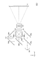
以下、図2を参照して投写光学系30の詳細について説明する。
図2は、第1実施形態の投写光学系30の構成の一例を示す図である。
ここで、図2に示す直交座標系について説明する。X軸は、プロジェクター1の横方向を示す。Y軸は、プロジェクター1の縦方向を示す。Z軸は、プロジェクター1の前後方向を示す。以降の記載において、X軸の方向を横方向とも記載する。また、X軸の正の方向を右方向、及びX軸の負の方向を左方向とも記載する。また、以降の記載において、Y軸の方向を縦方向とも記載する。また、Y軸の正の方向を下方向、及びY軸の負の方向を上方向とも記載する。また、以降の記載において、Z軸の方向を前後方向とも記載する。また、Z軸の正の方向を前方、及びZ軸の負の方向を後方とも記載する。
投写光学系30は、光源302と、3枚のミラー304a、304b、304cと、2枚のダイクロイックミラー306a、306bと、3枚の液晶表示素子308R、308G、308Bと、ダイクロイックプリズム310と、光路偏向素子20と、投写レンズ系312と、リレーレンズ314と、を備えている。
[Details of the projection optical system]
Hereinafter, details of the projection
FIG. 2 is a diagram showing an example of the configuration of the projection
Here, the Cartesian coordinate system shown in FIG. 2 will be described. The X axis indicates the horizontal direction of the projector 1. The Y axis represents the vertical direction of the projector 1. The Z axis indicates the front-back direction of the projector 1. In the following description, the direction of the X axis will also be described as the lateral direction. Further, the positive direction of the X axis is also referred to as the right direction, and the negative direction of the X axis is also referred to as the left direction. In the following description, the Y-axis direction will also be referred to as the vertical direction. Further, the positive direction of the Y-axis is also referred to as the downward direction, and the negative direction of the Y-axis is also referred to as the upward direction. Moreover, in the following description, the direction of the Z axis is also referred to as the front-back direction. Further, the positive direction of the Z axis is also referred to as the front, and the negative direction of the Z axis is also referred to as the rear.
The projection
光源302は、例えば、ハロゲンランプ、水銀ランプ、発光ダイオード(LED)又は半導体レーザー等である。また、この光源302は、白色光が出射するものが用いられる。
3枚のミラー304a、304b、304cは、それぞれ反射によりプロジェクター1内における光路を変換する機能を有する。一方、2枚のダイクロイックミラー306a、306bは、それぞれ光源302から出射した白色光をR(赤)、G(緑)、B(青)の3原色に分離し、互いに異なる液晶表示素子308R、308G、308Bにそれぞれ分離した光を導く機能を有する。
例えば、ダイクロイックミラー306aは、白色光のうち、Rの波長域の光を透過し、G、Bの波長域の光を反射する機能を有する。ダイクロイックミラー306bは、ダイクロイックミラー306aで反射したG、Bの波長域の光のうち、Bの波長域の光を透過し、Gの波長域の光を反射する機能を有する。
The
Each of the three
For example, the
なお、ダイクロイックミラー306a、306bによる反射により、Bの波長域の光の光路長は、他の光の光路長に比べて長くなる。このため、Bの波長域の光路の途中にリレーレンズ314を設けることにより、光路長のずれを補正している。
Note that the optical path length of the light in the wavelength range of B becomes longer than the optical path lengths of other lights due to the reflection by the
上述したように、液晶表示素子308R、308G、308Bは、それぞれ光変調装置として用いられる。これらの液晶表示素子308R、308G、308Bは、それぞれR、G、Bの原色に対応する透過型の光変調装置であり、矩形(長方形)状の画素領域内に、例えば縦1080行、横1920列のマトリクス状に配列した画素を備えている。各画素では、入射光に対する透過光の光量が調整され、各液晶表示素子308R、308G、308Bにおいて全画素の光量分布が協調制御される。
また、液晶表示素子308R、308G、308Bには、各画素に対応して走査線およびデータ線が設けられている(図示せず)。さらに、走査線とデータ線とが交差する位置に対応して画素電極とこれに対向して配置された共通電極との間に液晶が配置されている(図示せず)。
これらに加え、各液晶表示素子308R、308G、308Bには、図示しない偏光板が設けられている。そして、走査線の選択によってデータ線の電圧が画素電極に印加されると、液晶分子が配向し、透過光を偏光させる。このような液晶分子による偏光と偏光板の配置とを適宜設定することにより、画素ごとに透過光の光量を調整することができる。
液晶表示素子308R、308G、308Bによってそれぞれ空間的に変調された光は、ダイクロイックプリズム310に対し3方向から入射する。入射した光のうち、R、Bの波長域の光は、90°屈折して出射する。一方、Gの波長域の光は、直進して出射する。その結果、ダイクロイックプリズム310から出射する光は、R、G、Bの各原色からなる画像が合成されたフルカラーの画像を含む画像光となり、光路偏向素子20に入射する。
As described above, the liquid
Further, the liquid
In addition to these, each liquid
The light spatially modulated by the liquid
光路偏向素子20については、後に詳述するが、光学部材を有しており、この光学部材に入射される光を偏向(シフト)させるか否かを適宜選択することが可能である。このような偏向を受けた光は、光路偏向素子20から出射されて投写レンズ系312に入射する。投写レンズ系312は、複数のレンズが組み合わされた複合レンズ系である。この投写レンズ系312において合成された画像が拡大され、投写面8に投写される。
なお、振動検出部40は図2に示した投写光学系30の内部、さらにはダイクロイックプリズム310上に設けられるのが望ましい。
As will be described later in detail, the optical
It is desirable that the
[光路偏向素子について]
以下、図3及び図4を参照して光路偏向素子20について説明する。
図3は、第1実施形態の光路偏向素子20の構成の一例を示す斜視図である。
図4は、第1実施形態の光路偏向素子20の構成の一例を示す上面図である。
ここで、図3及び図4に示す直交座標系は、図2に示す直交座標系と同一の方向を示す。
[About optical path deflector]
Hereinafter, the optical
FIG. 3 is a perspective view showing an example of the configuration of the optical
FIG. 4 is a top view showing an example of the configuration of the optical
Here, the orthogonal coordinate system shown in FIGS. 3 and 4 shows the same direction as the orthogonal coordinate system shown in FIG.
光路偏向素子20は、光を偏向させる光学部材202と、光学部材202の側面を囲う第1枠体部204と、縦空隙部206Yを介して第1枠体部204から離間し、第1枠体部204の側面を囲う枠状の第2枠体部205と、横空隙部206Xを介して第2枠体部205から離間し、第2枠体部205の側面を囲う枠状の支持部208と、第1枠体部204と第2枠体部205とを連結するように設けられた縦軸部210Yと、第2枠体部205と支持部208とを連結するように設けられた横軸部210Xと、を備えている。このうち、光学部材202は、横軸部210X及び縦軸部210Yを揺動軸として揺動されることにより、その姿勢が変化するように構成されている。そして、光学部材202の姿勢が変化するとともに、光学部材202を透過した光の出射方向を変化させる(光路の位置を変化させる)ことができる。これにより、ダイクロイックプリズム310で合成された画像光を、任意の方向に偏向させることができる。
The optical
なお、以降の記載において、上述した光学部材202、第1枠体部204、第2枠体部205、支持部208、横軸部210X及び縦軸部210Yを、総称して光路偏向機能部200と記載する。
In the following description, the
光路偏向素子20は、光学部材202を揺動させて、その姿勢を変化させる横駆動部220X及び縦駆動部220Yを備える。光路偏向素子20は、横駆動部220X及び縦駆動部220Yによって生じる駆動力により、光学部材202を揺動する。
The optical
また、光路偏向素子20は、光路偏向機能部200の後方に設けられているベース240と、光路偏向機能部200とベース240との間に設けられたスペーサー250と、を備えている。
Further, the optical
[光路偏向機能部について]
光学部材202は、光透過性を有する板状体で構成されている。光学部材202に入射した光は、その入射角度に応じて、光学部材202を直進しつつ透過する。また、光学部材202に入射した光は、その入射角度に応じて、屈折しつつ透過する。したがって、目的とする入射角度になるように光学部材202の姿勢を変化させることによって、透過光が偏向する向き及び透過光の偏向の大きさを制御することができる。
[About optical path deflection function section]
The
光学部材202の構成材料は、例えば、水晶、サファイアのような各種結晶材料、ホウケイ酸ガラス、石英ガラスのような各種ガラス材料、ポリカーボネート系樹脂、アクリル系樹脂のような各種樹脂材料等である。これらの中でも、無機系材料が好ましく用いられる。無機系材料によれば、光学部材202の弾性が小さくなる。つまり、無機系材料によれば、剛性が大きくなり、光学部材202によって偏向される画像の偏向ムラが抑制される。
The constituent material of the
また、光学部材202は、矩形状をなしている。光学部材202の平面視における大きさや向きは、ダイクロイックプリズム310から出射する画像光が透過できるように適宜設定される。
The
第1枠体部204及び第2枠体部205は、光学部材202の側面を囲うように設けられている。第1枠体部204及び第2枠体部205は、光学部材202の構成材料よりも弾性が大きい弾性材料で構成されている。このような材料で構成されることにより、第1枠体部204及び第2枠体部205は、揺動に伴って発生する応力が光学部材202自体の不要な振動に繋がることを、最小限に抑えることができる。すなわち、弾性を有する第1枠体部204及び第2枠体部205が光学部材202の側面を囲っていることにより、光学部材202の姿勢を変更する際、光学部材202に生じる応力を小さく抑え、応力分布に伴って光学部材202に発生する不要な振動を小さく抑えることができる。その結果、光学部材202によって偏向される画像が、意図しない方向に偏向されてしまうことを防止することができる。
The first
第1枠体部204の外側には、縦空隙部206Yを介して、第1枠体部204の側面を囲うように第2枠体部205が設けられている。そして、第1枠体部204と第2枠体部205との間は、2本の縦軸部210Yを介して接続されている。また、第2枠体部205の外側には、横空隙部206Xを介して、第2枠体部205の側面を囲うように枠状の支持部208が設けられている。そして、第2枠体部205と支持部208との間は、2本の横軸部210Xを介して接続されている。
A second
第2枠体部205は、2本の横軸部210Xを介して支持部208に支持される。また、第1枠体部204は、2本の縦軸部210Yを介して第2枠体部205に支持される。これにより、第1枠体部204および光学部材202は、横軸部210Xを通る直線を揺動軸として揺動可能になるとともに、縦軸部210Yを通る直線を揺動軸として揺動可能になる。
The second
これらの第1枠体部204、第2枠体部205、支持部208、横軸部210X及び縦軸部210Yは、それぞれ別体のものが接着されることで形成されてもよいが、好ましくは一体に形成されている。これにより、第1枠体部204、第2枠体部205、横軸部210X及び縦軸部210Yの接続部や支持部208、横軸部210X及び縦軸部210Yの接続部の耐衝撃性や長期耐久性が高くなる。
また、横軸部210X及び縦軸部210Yの構成材料には、前述した第1枠体部204及び第2枠体部205を構成する弾性材料と同じ材料が用いられる。
さらに、支持部208の構成材料は、特に限定されず、樹脂材料以外の材料であってもよいが、好ましくは樹脂材料とされる。第1枠体部204、第2枠体部205、横軸部210X及び縦軸部210Yと、支持部208とが一体に形成されている場合には、支持部208には前述した第1枠体部204及び第2枠体部205を構成する弾性材料と同じ材料が用いられる。
このような弾性材料は、光学部材202の構成材料よりも弾性が大きい材料であれば、特に限定されないが、樹脂を主成分とする材料が好ましく用いられる。樹脂を含む材料であれば、光学部材202の構成材料よりも十分に弾性を大きくすることができるので、第1枠体部204及び第2枠体部205がもたらす上述したような効果がより顕著になる。
The first
Further, as the constituent material of the
Further, the constituent material of the
The elastic material is not particularly limited as long as it is a material having elasticity larger than that of the constituent material of the
また、2本の横軸部210Xは、それぞれ光学部材202の2つの長辺のうち、互いに異なる長辺に対応する位置に設けられている。そして、2本の横軸部210Xは、それぞれ、Y軸に対して平行に構成されている。
また、2本の縦軸部210Yは、それぞれ光学部材202の2つの短辺のうち、互いに異なる短辺に対応する位置に設けられている。そして、2本の縦軸部210Yは、それぞれ、X軸に対して平行に構成されている。
すなわち、第1枠体部204、第2枠体部205及び光学部材202が揺動する揺動軸は、X軸とY軸の双方に対して平行な軸である。
Further, the two
Further, the two
That is, the swing axis around which the first
また、2本の縦軸部210Y及び2本の横軸部210Xは、光学部材202の平面視における中心に対して点対称の関係を満足する位置に配置されていることが好ましい。これにより、揺動のバランスが良好になり、光学部材202を安定的に揺動させることができるようになり、画像の偏向挙動も安定する。その結果、プロジェクター1は、解像度の高い画像を安定的に投写することができる。
Further, it is preferable that the two
なお、上述では、第1枠体部204は、光学部材202の側面全体を囲うように構成されている場合について説明したが、必ずしも全体を囲っている必要はなく、例えば、光学部材202の一部を囲っていてもよい。
また、上述では、第2枠体部205及び支持部208は、枠状をなしている場合について説明したが、このような形状に限定されず、横軸部210X及び縦軸部210Yを保持し得る形状であればいかなる形状であってもよい。
なお、光学部材202と第1枠体部204との間は、いかなる方法で接着されていてもよいが、例えば接着剤を介して接着されている。接着剤は、例えば、エポキシ系接着剤、アクリル系接着剤又はシリコン系接着剤等である。
In the above description, the case where the first
Further, although the case where the second
The
[横駆動部及び縦駆動部について]
横駆動部220Xは、第2枠体部205を前後方向に貫通する貫通孔221Xと、貫通孔221Xを囲うように第2枠体部205上に載置された環状のコイル222Xと、ベース240の上面に載置され、貫通孔221X内に挿通されているコア223Xと、コア223Xに隣接して設けられた磁石224Xと、を備えている。
また、縦駆動部220Yは、第1枠体部204を前後方向に貫通する貫通孔221Yと、貫通孔221Yを囲うように第1枠体部204上に載置された環状のコイル222Yと、ベース240の上面に載置され、貫通孔221Y内に挿通されているコア223Yと、コア223Yに隣接して設けられた磁石224Yと、を備えている。
[About horizontal drive and vertical drive]
The
The
貫通孔221Xは、第2枠体部205の2つの短辺の付近に当該短辺と平行な位置にそれぞれ形成された細長い開口を有する孔である。また、貫通孔221Yは、第1枠体部204の2つの長辺の付近に当該長辺と平行な位置にそれぞれ形成された細長い開口を有する孔である。貫通孔221X及び貫通孔221Yの開口の形状は、矩形状(長方形)をなしているが、特に限定されるものではない。ただし、貫通孔221Xには、コア223Xが挿通される。また、貫通孔221Yには、コア223Yが挿通される。この場合、貫通孔221Xとコア223Xとが接触しないことが好ましい。また、貫通孔221Yとコア223Yとが接触しないことが好ましい。
したがって、貫通孔221Xとコア223Xとの間には、光学部材202が揺動する過程で常に隙間が生じるようになっていることが望まれる。また、貫通孔221Yとコア223Yとの間には、光学部材202が揺動する過程で常に隙間が生じるようになっていることが望まれる。
The through
Therefore, it is desirable that a gap be always formed between the through
コイル222Xは、第2枠体部205の上面に接着されている。また、コイル222Yは、第1枠体部204の上面に接着されている。コイル222X及びコイル222Yは、環状をなしている。また、コイル222Xがなす環の形状と貫通孔221Xの開口の形状とが、ほぼ一致するように構成されている。また、コイル222Yがなす環の形状と貫通孔221Yの開口の形状とが、ほぼ一致するように構成されている。
The
コア223X及びコア223Yは、部分的に折り曲げられた板状の磁心である。コア223Xは、枠状をなす支持部208の短辺部分を跨ぐように設けられている。また、コア223Yは、枠状をなす支持部208の長辺部分を跨ぐように設けられている。
コア223X及びコア223Yは、例えば、純鉄、ソフトフェライト又はパーマロイ等の軟磁性材料で構成される。
The
The
[コイルの制御による光学部材の移動について]
コイル222X及びコイル222Yは、図示しない電圧印加手段に接続されている。
コア223Xには、隣接して磁石224Xが配置される。電圧印加手段によってコイル222Xに電圧が印加されると、コイル222X付近に磁界が発生する。コイル222Xに電圧が印加される印加方向と磁石224Xの磁界の方向によって、コア223Xには、前後方向に駆動する磁力が発生する。この磁力によって第2枠体部205及び光学部材202は、横軸部210Xを中心軸として前後方向に回転する。
[Movement of optical member by controlling coil]
The
A
また、コア223Yには、隣接して磁石224Yが配置される。電圧印加手段によってコイル222Yに電圧が印加されると、コイル222Y付近に磁界が発生する。コイル222Yに電圧が印加される印加方向と、磁石224Yの磁界の方向によって、コア223Yには、前後方向に駆動する磁力が発生する。この磁力によって第1枠体部204及び光学部材202は、縦軸部210Yを中心軸として前後方向に回転する。
A
電圧印加手段によってコイル222X及びコイル222Yに電圧が印加されると、コイル222X及びコイル222Y付近に磁界が発生する。コイル222X及びコイル222Yに電圧が印加される方向と、磁石224X及び磁石224Yの磁界の方向によって、第1枠体部204及び光学部材202の4つの頂点である右上頂点、右下頂点、左上頂点及び左下頂点を前後方向に回転する。
具体的には、コイル222X及びコイル222Yに電圧が印加される印加方向によって、第1枠体部204及び光学部材202は、第1枠体部204及び光学部材202の右上頂点及び左下頂点を結ぶ直線と直交する軸を中心軸として前後方向に回転する。また、コイル222X及びコイル222Yに電圧が印加される印加方向によっては、第1枠体部204及び光学部材202の右下頂点及び左上頂点を結ぶ直線と直交する軸を中心軸として前後方向に回転する。
When a voltage is applied to the
Specifically, the first
磁石224X及び磁石224Yは、例えば永久磁石で構成される。永久磁石は、例えば、ネオジウム磁石、フェライト磁石、サマリウムコバルト磁石又はアルニコ磁石等である。
The
上述したように、横駆動部220X及び縦駆動部220Yが駆動することにより、光学部材202を透過する画像光を偏向させる投写方向の変化量が変化される。つまり、光路偏向素子20を透過する画像光は、横駆動部220X及び縦駆動部220Yを駆動することにより、投写面8に投写される画像光の位置が変化する。駆動部220は、光路偏向制御部13が出力する第1制御信号CT1に基づいて、駆動する。
As described above, the
なお、上述した磁力を用いた駆動部220は、駆動部の一例であり、駆動部220は、第1枠体部204および光学部材202を駆動する他の手段で代替可能である。他の手段は、例えば、圧電駆動等である。
また、駆動部220が設けられる位置や数も、本実施形態の態様に限定されない。
The
Further, the position and the number of the
[駆動部の駆動:プロジェクターに加えられる振動を補正する場合]
駆動部220は、プロジェクター1に加えられる振動が第1しきい値以上である場合、振動の大きさに応じて、光路偏向素子20が偏向する画像光の投写方向の変化量を変更するように駆動する。
この場合、光路偏向制御部13は、プロジェクター1に加えられる振動を打ち消す位置にプロジェクター1が投写する画像光を移動するように駆動部220を制御する第1制御信号CT1を駆動部220に出力する。
具体的には、光路偏向制御部13は、横駆動部220X及び縦駆動部220Yを、第1制御信号CT1に基づいて制御し、投写面8に投写される画像光の位置が、プロジェクター1に加えられる振動を打ち消す位置になるように光路偏向素子20が偏向する画像光の投写方向の変化量を変更する。プロジェクター1に加えられる振動を打ち消す位置とは、振動情報Vに含まれる方向情報DRとは逆の方向であって、画像光が投写される位置から変位情報DPが示す距離だけ移動した位置である。
[Driving the driving unit: When correcting the vibration applied to the projector]
When the vibration applied to the projector 1 is equal to or larger than the first threshold value, the
In this case, the optical path
Specifically, the optical path
[駆動部の駆動:画像を高解像度で投写する場合]
駆動部220は、プロジェクター1に加えられる振動が第1しきい値未満である場合、画像が高解像度で投写されるように駆動する。
[Driving the drive unit: When projecting an image with high resolution]
When the vibration applied to the projector 1 is less than the first threshold value, the driving
ここで、光学部材202によって偏向を受ける画像を構成する画素群は、通常、X軸に平行して配列した画素の列がY軸に沿って並んでできる画素の集合体である。すなわち、この画素群は、XY平面に行列状に配置されている。この画素数は、特に限定されないが、例えばX軸方向に1920列、Y軸方向に1080列とされる。
画素が行列状に配置されてなる画像(画素群)は、光学部材202を透過する際に偏向を受けるが、光学部材202の揺動軸がX軸とY軸の双方に対して斜めに傾いていると、画像の偏向方向もX軸とY軸の双方に対して斜め方向に沿うこととなる。このため、光路を偏向させずに画像光を投写する状態と、縦と横の双方に対して画素ピッチの1/2だけずらした方向に画像光を投写する状態とを交互に繰り返すことにより、画像の縦と横の画素をそれぞれ実質的に増やし、投写される画像の高解像度化を図ることができる。
以降の記載において、光路を偏向させずに画像光が投写される方向を、第1の方向と記載する。また、以降の記載において、光路を変更させることにより、縦と横の双方に対して画素ピッチの1/2だけずれて画像光が投写される方向を、第2の方向と記載する。
Here, the pixel group that constitutes an image that is deflected by the
An image (pixel group) in which pixels are arranged in a matrix is deflected when passing through the
In the following description, the direction in which the image light is projected without deflecting the optical path is referred to as the first direction. Further, in the following description, a direction in which the image light is projected with a shift of ½ of the pixel pitch in both the vertical and horizontal directions by changing the optical path is referred to as a second direction.
なお、画像光のずらし量は、画素ピッチの1/2以外であってもよい。また、上述では、2つの状態のうちの一方では、光路を偏向させずに画像光を投写させているが、投写方向が所定量(例えば、画素ピッチの1/2)だけずれていれば、双方の状態において光路が偏向されていてもよい。 The shift amount of the image light may be other than 1/2 of the pixel pitch. Further, in the above, in one of the two states, the image light is projected without deflecting the optical path, but if the projection direction is deviated by a predetermined amount (for example, 1/2 of the pixel pitch), The optical path may be deflected in both states.
光路偏向制御部13は、画像が高解像度で投写されるように駆動部220を制御する第1制御信号CT1を駆動部220に出力する。
The optical
[ベースについて]
ベース240は、板状をなしており、光路偏向機能部200を支持するとともに、光路偏向素子20の機械的強度を確保する。
ベース240は、平面視で光路偏向機能部200より一回り大きい矩形状をなしており、縁部が光路偏向機能部200の外縁からはみ出すように構成されている。このはみ出した部分には、前述したコア223X及びコア223Yが接続される。
ベース240の構成材料は、例えば、ガラス、シリコン、金属又はセラミックスのような無機材料、樹脂のような有機材料等である。
また、ベース240には、光学部材202の位置に対応して、前後方向に貫通する貫通孔241が形成されている。この貫通孔241を設けて、当該貫通孔241に光路偏向素子20が配置されることにより、光路偏向素子20を介して画像光を透過させることができる。
[About the base]
The
The
The constituent material of the
Further, a through
なお、ベース240の形状は、光路偏向機能部200を支持し得る形状であれば、本実施形態の態様に限定されない。
The shape of the
[スペーサーについて]
スペーサー250は、光路偏向機能部200とベース240との間に介挿されている。スペーサー250は、枠状をなしており、その内壁とベース240の上面と光路偏向機能部200の下面とによって空間251(不図示)が画成されている。この空間251は、第1枠体部204、第2枠体部205及び光学部材202の揺動を許容するための空間である。
[About spacers]
The
スペーサー250は、光路偏向機能部200と同一形状かつ同一寸法となっている。なお、このようなスペーサー250の形状は、第1枠体部204及び第2枠体部205等の揺動を許容する空間を形成し得る形状であれば、特に限定されず、例えば枠状をなしていなくてもよく、光路偏向機能部200と同一寸法かつ同一形状でなくてもよい。
スペーサー250の構成材料は、例えば、ガラス、シリコン、金属又はセラミックスのような無機材料、樹脂のような有機材料等である。
The
The constituent material of the
[プロジェクターの動作について]
以下、図5及び図6を参照してプロジェクター1の動作について説明する。
図5は、第1実施形態の光路偏向素子20の制御に伴うプロジェクター1の動作の一例を示す流れ図である。
図5に示す通り、振動検出部40は、プロジェクター1に加えられる振動を検出する(ステップS110)。振動検出部40は、検出した振動情報Vを制御部10に出力する(ステップS120)。
[About projector operation]
The operation of the projector 1 will be described below with reference to FIGS. 5 and 6.
FIG. 5 is a flow chart showing an example of the operation of the projector 1 according to the control of the optical
As shown in FIG. 5, the
制御部10が備える振動情報取得部11は、振動検出部40から振動情報Vを取得する(ステップS130)。振動情報取得部11は、取得した振動情報Vを振動判定部12に出力する(ステップS140)。
振動判定部12は、振動情報取得部11から振動情報Vを取得する(ステップS150)。振動判定部12は、振動情報取得部11から取得した振動情報Vが第1しきい値以上であるか否かを判定する(ステップS160)。振動判定部12は、振動情報Vが第1しきい値以上である場合(ステップS160;YES)、光路偏向制御部13に振動情報Vを出力する(ステップS170)。また、振動判定部12は、振動情報Vが第1しきい値未満である場合(ステップS160;NO)、光路偏向制御部13に振動情報Vを出力しない(ステップS180)。
The vibration
The
光路偏向制御部13は、振動判定部12から振動情報Vを取得するか否かを判定する(ステップS190)。光路偏向制御部13は、振動判定部12から振動情報Vを取得する場合(ステップS190;YES)、プロジェクター1に加えられる振動に応じて、駆動部220を制御する第1制御信号CT1を生成する(ステップS200)。また、光路偏向制御部13は、振動判定部12から振動情報Vを取得しない場合(ステップS190;NO)、プロジェクター1が投写する画像を高解像によって投写するように駆動部220を制御する第1制御信号CT1を生成する(ステップS210)。
光路偏向制御部13は、第1制御信号CT1を投写光学系30に出力する(ステップS220)。
投写光学系30の光路偏向素子20が備える駆動部220は、光路偏向制御部13から出力される第1制御信号CT1に基づいて、駆動する(ステップS230)。
The optical
The optical path
The
図6は、第1実施形態の液晶表示素子308の制御に伴うプロジェクター1の動作の一例を示す流れ図である。
画像取得部15は、入力ポートから画像を示す画像情報PIを取得する(ステップS240)。画像取得部15は、取得した画像情報PIを表示素子制御部16に出力する(ステップS250)。
表示素子制御部16は、画像取得部15から画像情報PIを取得する(ステップS260)。表示素子制御部16は、取得した画像情報PIに基づいて、液晶表示素子308に画像情報PIが示す画像を形成する制御を行う(ステップS270)。
投写光学系30が備える液晶表示素子308には、表示素子制御部16の制御に応じて、画像を形成する(ステップS280)。
FIG. 6 is a flow chart showing an example of the operation of the projector 1 according to the control of the liquid
The
The display
An image is formed on the liquid
[第1実施形態のまとめ]
以上説明したように、本実施形態のプロジェクター(第1実施形態の一例では、プロジェクター1)は、投写面(第1実施形態の一例では、投写面8)に画像光を投写するプロジェクターであって、光源から射出された光を画像光に変調する光変調装置(第1実施形態の一例では、液晶表示素子308)と、光変調装置で変調された画像光の投写方向を変化させる光路偏向部(第1実施形態の一例では、光路偏向素子20)と、光路偏向部から出力された画像光を投写面に投写する投写光学系(第1実施形態の一例では、投写光学系30)と、プロジェクターに加わる振動を検出する振動検出部(第1実施形態の一例では、振動検出部40)と、振動検出部で検出された振動に基づいて、光路偏向部による投写方向の変化量を制御する光路偏向制御部(第1実施形態の一例では、光路偏向制御部13)とを有する。
[Summary of First Embodiment]
As described above, the projector of this embodiment (the projector 1 in the example of the first embodiment) is a projector that projects image light on the projection surface (the
本実施形態のプロジェクターは、光路偏向制御部は、振動が第1しきい値以上の場合には、振動に基づいて、光路偏向部による投写方向の変化量を制御し、振動が前記第1しきい値未満の場合には、光路偏向部により画像光の投写方向を第1の方向と第2の方向に交互に変化させる。 In the projector according to the present embodiment, the optical path deflection control unit controls the amount of change in the projection direction by the optical path deflection unit based on the vibration when the vibration is equal to or greater than the first threshold, and the vibration causes the first vibration. When it is less than the threshold value, the projection direction of the image light is alternately changed to the first direction and the second direction by the optical path deflecting unit.
本実施形態のプロジェクターは、光路偏向部は、姿勢に応じて光を偏向させる光学部材(第1実施形態の一例では、光学部材202)と、光学部材の姿勢を変化させる駆動部(第1実施形態の一例では、駆動部220)と、を備える。駆動部は、光路偏向制御部の制御に基づいて、光路偏向部による投写方向が変化するように駆動する。
In the projector of the present embodiment, the optical path deflecting unit includes an optical member that deflects light according to the posture (the
本実施形態のプロジェクター1は、プロジェクター1に加えられる振動が第1しきい値以上であるか否かに基づいて、駆動部220の駆動の制御を変更する。プロジェクター1は、プロジェクター1に加えられる振動が第1しきい値以上である場合、プロジェクター1に加えられる振動を打ち消す位置にプロジェクター1が投写する画像光を移動する。また、プロジェクター1は、プロジェクター1に加えられる振動が第1しきい値未満である場合、プロジェクター1が投写する画像光を高解像度で投写する。
これにより、本実施形態のプロジェクター1では、プロジェクター1に加えられる振動に応じて画像のブレを補正することができる。
The projector 1 of the present embodiment changes the drive control of the
As a result, in the projector 1 of the present embodiment, it is possible to correct the blurring of the image according to the vibration applied to the projector 1.
[変形例]
以下、図を参照して第1実施形態に係る変形例について説明する。
図7は、変形例の縦光路偏向素子4の一例を示す図である。
図8は、変形例の横光路偏向素子5の一例を示す図である。
第1実施形態では、駆動部220である横駆動部220X及び縦駆動部220Yが同一のベース240に形成され、一体の光路偏向素子20である場合について説明したが、これに限られない。例えば、横駆動部220X及び縦駆動部220Yは、異なるベース240に形成されていてもよい。
以下、図7及び図8を参照して、横駆動部220X及び縦駆動部220Yがそれぞれ異なるベース240A及びベース240Bに形成される一例について説明する。
なお、上述した第1実施形態と同様の構成については、同一の符号を付してその説明を省略する。
[Modification]
Hereinafter, a modified example according to the first embodiment will be described with reference to the drawings.
FIG. 7 is a diagram showing an example of a vertical optical path deflecting element 4 of a modified example.
FIG. 8 is a diagram showing an example of a lateral optical path deflecting element 5 of a modified example.
In the first embodiment, the case where the
Hereinafter, an example in which the
The same components as those in the first embodiment described above are designated by the same reference numerals, and the description thereof will be omitted.
縦光路偏向素子4は、ベース240A上に光を偏向させる光学部材202Aと、光学部材202Aの側面を囲う枠体部204Aと、縦空隙部206Yを介して枠体部204Aから離間し、枠体部204Aの側面を囲う枠状の支持部208Aと、枠体部204Aと支持部208Aとを連結するように設けられた縦軸部210Yと、を備えている。ベース240Aには、光学部材202Aの位置に対応して、前後方向に貫通する貫通孔241Aが形成されている。この貫通孔241Aを設けて、当該貫通孔241Aに光学部材202Aが配置されることにより、光学部材202Aを介して画像光を透過させることができる。
このうち、光学部材202Aは、縦軸部210Yを揺動軸として揺動されることにより、その姿勢が変化するように構成されている。そして、光学部材202Aの姿勢が変化するとともに、光学部材202Aを透過した光の出射方向を変化させる(光路の位置を変化させる)ことができる。これにより、ダイクロイックプリズム310で合成された画像光を、縦軸部210Yを中心軸として上下方向に偏向させることができる。
The vertical optical path deflecting element 4 is separated from the
Of these, the
横光路偏向素子5は、光を偏向させる光学部材202Bと、光学部材202Bの側面を囲う枠体部204Bと、横空隙部206Xを介して枠体部204Bから離間し、枠体部204Bの側面を囲う枠状の支持部208Bと、枠体部204Bと支持部208Bとを連結するように設けられた横軸部210Xと、を備えている。ベース240Bには、光学部材202Bの位置に対応して、前後方向に貫通する貫通孔241Bが形成されている。この貫通孔241Bを設けて、当該貫通孔241Bに光学部材202Bが配置されることにより、光学部材202Bを介して画像光を透過させることができる。
このうち、光学部材202Bは、横軸部210Xを揺動軸として揺動されることにより、その姿勢が変化するように構成されている。そして、光学部材202Bの姿勢が変化するとともに、光学部材202Bを透過した光の出射方向を変化させる(光路の位置を変化させる)ことができる。これにより、ダイクロイックプリズム310で合成された画像光を、横軸部210Xを中心軸として左右方向に偏向させることができる。
The lateral optical path deflecting element 5 is separated from the
Among them, the
縦光路偏向素子4及び横光路偏向素子5は、前後方向に重ねて配置される。また、縦光路偏向素子4が備える光学部材202Aと、横光路偏向素子5が備える光学部材202Bとは、ダイクロイックプリズム310から射出される画像光が投写面8に投写することができる位置に配置される。
The vertical optical path deflecting element 4 and the horizontal optical path deflecting element 5 are arranged to overlap each other in the front-rear direction. Further, the
[第2実施形態]
[プロジェクターの構成について]
以下、図を参照して本発明の第2実施形態について説明する。
図9は、第2実施形態のプロジェクター2の構成の一例を示す図である。
第1実施形態では、プロジェクター1に加えられる振動が第1しきい値以上である場合、振動情報Vに基づいて、光路偏向素子20が偏向する画像光の投写方向の変化量を変更する場合について説明した。
第2実施形態では、プロジェクター2に加えられる振動が第2しきい値以上である場合、振動情報Vに基づいて、光路偏向素子20が偏向する画像光の投写方向の変化量を変更し、かつ光路偏向素子20の姿勢を変化させる点において第1実施形態と異なる。
なお、上述した第1実施形態及び変形例と同一の構成については、同一の符号を付してその説明を省略する。
[Second Embodiment]
[About the configuration of the projector]
Hereinafter, a second embodiment of the present invention will be described with reference to the drawings.
FIG. 9 is a diagram showing an example of the configuration of the
In the first embodiment, when the vibration applied to the projector 1 is equal to or higher than the first threshold value, the change amount of the projection direction of the image light deflected by the optical
In the second embodiment, when the vibration applied to the
The same components as those in the first embodiment and the modification described above are designated by the same reference numerals and the description thereof will be omitted.
プロジェクター2は、振動検出部40と、制御部100と、投写光学系31とを備える。
制御部100は、CPUを備えており、振動情報取得部11と、振動判定部12と、光路偏向制御部13と、画像取得部15と、表示素子制御部16と、姿勢調整制御部14とをその機能部として備える。投写光学系31は、光路偏向素子20と、姿勢調整部260と、液晶表示素子308とを備える。
The
The
[姿勢調整部について]
姿勢調整部260は、ベース240の後方にベース240に接して配置される。
姿勢調整部260は、制御部100の制御に基づいて、光路偏向素子20の姿勢を変化させる。姿勢調整部260は、例えば、複数のアクチュエーター等で構成される。姿勢調整部260は、制御部100から出力される第2制御信号CT2に基づいて光路偏向素子20の姿勢を変化させる(傾ける)。
[Posture adjustment unit]
The
The
[制御部について]
振動判定部12は、振動情報取得部11から取得した振動情報Vが示す振動の大きさを判定する。振動判定部12は、振動情報Vが示す振動が第1しきい値以上であるか否かを判定する。上述したように、振動判定部12は、振動情報Vが示す振動が第1しきい値未満である場合、光路偏向制御部13に振動情報Vを出力しない。この場合、光路偏向制御部13は、プロジェクター2が投写する画像を高解像度で投写するように駆動部220を制御する。
振動判定部12は、振動情報Vが示す振動が第1しきい値以上である場合、振動情報Vが示す振動が更に第2しきい値以上であるか否かを判定する。
[About control unit]
The
When the vibration indicated by the vibration information V is greater than or equal to the first threshold value, the
ここで、第2しきい値は、振動情報Vに含まれる変位情報DPが示す距離のしきい値である。具体的には、第2しきい値は、第1しきい値が示す距離より長い距離である。また、第2しきい値は、光路偏向素子20が偏向する画像光の進行の向き及び大きさを変更することにより投写面8に投写する画像光の位置を変更することができる距離である。
Here, the second threshold value is a threshold value of the distance indicated by the displacement information DP included in the vibration information V. Specifically, the second threshold is a distance longer than the distance indicated by the first threshold. Further, the second threshold value is a distance at which the position of the image light projected on the
振動判定部12は、プロジェクター2に加えられる振動が第1しきい値以上であって、かつ第2しきい値未満であると判定した場合、光路偏向制御部13に振動情報Vを出力し、光路偏向制御部13は、光路偏向素子20が偏向する画像光の変化量を変更し、プロジェクター12に加えられる振動を打ち消す位置に画像光が投写されるように駆動部220の駆動を制御する。
振動判定部12は、プロジェクター2に加えられる振動が第2しきい値以上であると判定した場合、振動情報Vを光路偏向制御部13及び姿勢調整制御部14に出力する。
When the
When the
姿勢調整制御部14は、振動判定部12から取得した振動情報Vに基づいて、姿勢調整部260を制御し、光路偏向素子20の姿勢を変化させる。
光路偏向制御部13は、振動判定部12から取得した振動情報Vに基づいて、光路偏向素子20が偏向する画像光の変化量を変更する。具体的には、光路偏向制御部13は、姿勢調整部260による光路偏向素子20の傾きと、光路偏向素子20における光学部材202の傾きとによってプロジェクター2に加えられる振動を打ち消す位置に画像光が投写されるように駆動部220の駆動を制御する。
The posture
The optical path
振動検出部40により検出された振動情報Vに基づく振動の大きさ(変位情報DPに応じた大きさ)が第2しきい値より大きい場合に、姿勢調整部260により光路偏向素子20の姿勢を変化させることによって、光路偏向素子20自体の傾きと、光路偏向素子20における光学部材202の傾きとを合わせた総合的な傾きに応じた距離だけ画像光を移動させることができる。本実施形態では、例えば、振動情報Vの方向情報DRに応じた向きに所定量だけ光路偏向素子20を傾けるとともに、この傾きによる画像光の移動距離を変位情報DPから引いた距離だけ駆動部220の駆動により画像光を移動させる。言い換えれば、第2しきい値と同等量だけ画像光が移動するように光路偏向素子20を傾けるとともに、第2しきい値を超える量だけ画像光が移動するように光路偏向素子20に対して光学部材202を傾ける。
When the magnitude of the vibration based on the vibration information V detected by the vibration detecting unit 40 (the magnitude corresponding to the displacement information DP) is larger than the second threshold value, the
光路偏向制御部13は、振動情報Vに基づいて、駆動部220の駆動を制御する第1制御信号CT1を投写光学系31に出力する。
また、姿勢調整制御部14は、振動情報Vに基づいて、姿勢調整部260の動作を制御する第2制御信号CT2を出力する。
The optical
Further, the posture
[第2実施形態のまとめ]
以上説明したように、本実施形態のプロジェクター(第2実施形態の一例では、プロジェクター2)は、光路偏向部(第2実施形態の一例では、光路偏向素子20)の姿勢を変化させる姿勢調整部(第2実施形態の一例では、姿勢調整部260)と、振動検出部(第2実施形態の一例では、振動検出部40)で検出された振動に基づいて、姿勢調整部を制御する姿勢調整制御部(第2実施形態の一例では、姿勢調整制御部14)を備え、振動が第2しきい値以上の場合、光路偏向制御部(第2実施形態の一例では、光路偏向制御部13)は、振動に基づいて、光路偏向部による投写方向の変化量を制御し、姿勢調整制御部は、振動に基づいて、姿勢調整部に光路偏向部の姿勢を変化させる。
[Summary of Second Embodiment]
As described above, the projector of the present embodiment (the
本実施形態のプロジェクター2は、プロジェクター2に加えられる振動が第2しきい値以上であるか否かに基づいて、駆動部220の駆動の制御及び姿勢調整部260の動作の制御を変更する。プロジェクター2は、プロジェクター2に加えられる振動が第2しきい値以上である場合、光路偏向素子20が偏向する画像光の変化量を変更し、光路偏向素子20の姿勢を変化させる。
これにより、本実施形態のプロジェクター2によれば、当該プロジェクター2に加えられるより大きい振動に応じて画像のブレを補正することができる。
The
As a result, according to the
[第1実施形態及び第2実施形態のまとめ]
また、第1実施形態及び第2実施形態のプロジェクター(第1実施形態の一例では、プロジェクター1、第2実施形態の一例では、プロジェクター2)は、投写面(第1実施形態及び第2実施形態の一例では、投写面8)に画像光を投写するプロジェクターであって、光源から射出された光を画像光に変調する光変調装置(第1実施形態及び第2実施形態の一例では、液晶表示素子308)と、光変調装置で変調された画像光の投写方向を変化させる光路偏向部(第1実施形態の一例では、光路偏向素子20、第2実施形態の一例では、光路偏向素子20)と、光路偏向部から出力された画像光を投写面に投写する投写光学系(第1実施形態の一例では、投写光学系30、第2実施形態の一例では、投写光学系31)と、プロジェクターに加わる振動を検出する振動検出部(第1実施形態及び第2実施形態の一例では、振動検出部40)と、振動検出部で検出された振動に基づいて、光路偏向部による投写方向の変化量を制御する光路偏向制御部(第1実施形態及び第2実施形態の一例では、光路偏向制御部13)とを有する。
[Summary of First and Second Embodiments]
In addition, the projectors of the first and second embodiments (the projector 1 in the example of the first embodiment and the
この構成により、プロジェクターでは、プロジェクターに加えられる振動に基づいて、光路偏向部による画像光の投写方向の変化量を変化させる。これにより、プロジェクターでは、プロジェクターに加えられる振動に応じて画像のブレを補正することができる。 With this configuration, the projector changes the amount of change in the projection direction of the image light by the optical path deflecting unit based on the vibration applied to the projector. As a result, the projector can correct the blur of the image according to the vibration applied to the projector.
なお、上述では、プロジェクター2に加えられる振動が第2しきい値より大きい場合には、光路偏向素子20が偏向する画像光の変化量を変更し、かつ光路偏向素子20の姿勢を変化させる制御を行う場合について説明したが、これに限られない。
他の例として、プロジェクター2に加えられる振動が第2しきい値より大きい場合、光路偏向素子20の姿勢を変化させる制御のみが行われてもよい。
In the above description, when the vibration applied to the
As another example, when the vibration applied to the
また、上述では、振動判定部12が第1しきい値に基づいて、プロジェクター2が投写する画像を高解像度で投写すること、又は振動情報Vに応じて光路偏向素子20が変更する画像光を投写する位置を移動することを判定し、第2しきい値に基づいて、光路偏向素子20が偏向する画像光の変化量を変更すること又は、光路偏向素子20が偏向する画像光の変化量を変更し、かつ光路偏向素子20の姿勢を変化させることを判定する場合について説明したが、これに限られない。
他の例として、振動判定部12は、第1しきい値及び第2しきい値とは異なるしきい値に基づいて、プロジェクター2が投写する画像を高解像度で投写すること又は、振動情報Vに応じて光路偏向素子20を移動することを判定してもよい。
Further, in the above description, the
As another example, the
また、上述では、振動情報Vに応じて、駆動部220が駆動し、光路偏向素子20が画像光を偏向することによる画像光の移動方向が、振動情報Vに含まれる方向情報DRと逆の方向である場合について説明したが、これに限られない。画像光の移動方向は、プロジェクター1及びプロジェクター2に加えられる振動を打ち消すことができる方向であれば、いずれの方向であってもよい。例えば、画像光の移動方向は、方向情報DRと逆の方向の斜め方向に移動されてもよい。
Further, in the above description, the moving direction of the image light due to the
また、上述では、振動情報Vに応じて、駆動部220が駆動し、光路偏向素子20が画像光を偏向することによる画像光が移動する距離が、振動情報Vに含まれる変位情報DPが示す距離である場合について説明したが、これに限られない。画像光が移動する距離は、プロジェクター2に加えられる振動を打ち消すことができる距離であれば、いずれの距離であってもよい。
Further, in the above description, the displacement information DP included in the vibration information V indicates the distance that the image light moves due to the
また、上記の各実施形態では、3つの液晶表示素子308R、308G、308Bを備えるプロジェクター1及びプロジェクター2を例示したが、DMD(Digital Micromirror Device:米国テキサスインツルメンツ社の登録商標)と呼ばれる反射型光変調素子を用いたDLP(Digital Light Processing:米国テキサスインツルメンツ社の登録商標)方式のプロジェクターであってもよい。
Further, in each of the above-described embodiments, the projector 1 and the
また、プロジェクター1及びプロジェクター2は、透過型の光変調装置である3つの液晶表示素子308R、308G、308Bを備える場合について説明したが、これに限られない。プロジェクター1及びプロジェクター2は、反射型の光変調装置を備えていていもよい。
Further, the projector 1 and the
なお、上記の各実施形態におけるプロジェクター1及びプロジェクター2が備える各部は、専用のハードウェアにより実現されるものであってもよく、また、メモリーおよびマイクロプロセッサにより実現させるものであってもよい。
Note that each unit included in the projector 1 and the
なお、プロジェクター1及びプロジェクター2が備える各部は、メモリーおよびCPU(中央演算装置)により構成され、プロジェクター1及びプロジェクター2が備える各部の機能を実現するためのプログラムをメモリーにロードして実行することによりその機能を実現させるものであってもよい。
Each unit included in the projector 1 and the
また、プロジェクター1及びプロジェクター2が備える各部の機能を実現するためのプログラムをコンピューター読み取り可能な記録媒体に記録して、この記録媒体に記録されたプログラムをコンピューターシステムに読み込ませ、実行することにより処理を行ってもよい。なお、ここでいう「コンピューターシステム」は、OSや周辺機器等のハードウェアを含むものとする。
In addition, a program for realizing the functions of the respective units included in the projector 1 and the
また、「コンピューターシステム」は、WWWシステムを利用している場合であれば、ホームページ提供環境(あるいは表示環境)も含むものとする。
また、「コンピューター読み取り可能な記録媒体」は、フレキシブルディスク、光磁気ディスク、ROM、CD−ROM等の可搬媒体、コンピューターシステムに内蔵されるハードディスク等の記憶装置のことをいう。さらに「コンピューター読み取り可能な記録媒体」は、インターネット等のネットワークや電話回線等の通信回線を介してプログラムを送信する場合の通信線のように、短時間の間、動的にプログラムを保持するもの、その場合のサーバやクライアントとなるコンピューターシステム内部の揮発性メモリーのように、一定時間プログラムを保持しているものも含むものとする。また上記プログラムは、前述した機能の一部を実現するためのものであってもよく、さらに前述した機能をコンピューターシステムにすでに記録されているプログラムとの組み合わせで実現できるものであってもよい。
Further, the “computer system” includes a homepage providing environment (or display environment) when using the WWW system.
The "computer-readable recording medium" refers to a portable medium such as a flexible disk, a magneto-optical disk, a ROM, a CD-ROM, and a storage device such as a hard disk built in a computer system. Furthermore, a "computer-readable recording medium" is one that dynamically holds a program for a short period of time, such as a communication line for transmitting the program via a network such as the Internet or a communication line such as a telephone line. , In that case, such as volatile memory inside the computer system that serves as a server or client, those that hold the program for a certain period of time are also included. Further, the program may be for realizing a part of the functions described above, or may be a program that can realize the functions described above in combination with a program already recorded in the computer system.
以上、本発明の各実施形態を、図面を参照して詳述してきたが、具体的な構成はこの実施形態に限られるものではなく、本発明の趣旨を逸脱しない範囲で適宜変更を加えることができる。上述した各実施形態に記載の構成を組み合わせてもよい。 As described above, the embodiments of the present invention have been described in detail with reference to the drawings. However, the specific configuration is not limited to the embodiments, and appropriate modifications may be made without departing from the spirit of the present invention. You can The configurations described in the above embodiments may be combined.
1、2…プロジェクター、20…光路偏向素子、10、100…制御部、40…振動検出部、30、31…投写光学系、11…振動情報取得部、12…振動判定部、13…光路偏向制御部、14…姿勢調整制御部、15…画像取得部、16…表示素子制御部、8…投写面、CT1…第1制御信号、CT2…第2制御信号、V…振動情報、DP…変位情報、DR…方向情報、4…縦光路偏向素子、5…横光路偏向素子、200…光路偏向機能部、202、202A、202B…光学部材、204…第1枠体部、205…第2枠体部、204A、204B…枠体部、206X…横空隙部、206Y…縦空隙部、208、208A、208B…支持部、210X…横軸部、210Y…縦軸部、220…駆動部、220X…横駆動部、220Y…縦駆動部、221X、221Y、241、241A、241B…貫通孔、222X、222Y…コイル、223X、223Y…コア、224X、224Y…磁石、240、240A、240B…ベース、250…スペーサー、251…空間、260…姿勢調整部、302…光源、304a、304b、304c…ミラー、306a、306b…ダイクロイックミラー、308、308B、308G、308R…液晶表示素子、310…ダイクロイックプリズム、312…投写レンズ系、314…リレーレンズ
1, 2... Projector, 20... Optical path deflecting element, 10, 100... Control section, 40... Vibration detection section, 30, 31... Projection optical system, 11... Vibration information acquisition section, 12... Vibration determination section, 13... Optical path deflection Control unit, 14... Attitude adjustment control unit, 15... Image acquisition unit, 16... Display element control unit, 8... Projection surface, CT1... First control signal, CT2... Second control signal, V... Vibration information, DP... Displacement Information, DR... Direction information, 4... Vertical optical path deflecting element, 5... Horizontal optical path deflecting element, 200... Optical path deflecting functional unit, 202, 202A, 202B... Optical member, 204... First frame body section, 205... Second frame Body part, 204A, 204B... Frame body part, 206X... Horizontal void part, 206Y... Vertical void part, 208, 208A, 208B... Support part, 210X... Horizontal axis part, 210Y... Vertical axis part, 220... Driving part, 220X ... lateral drive section, 220Y... vertical drive section, 221X, 221Y, 241, 241A, 241B... through hole, 222X, 222Y... coil, 223X, 223Y... core, 224X, 224Y... magnet, 240, 240A, 240B... base, 250... Spacer, 251... Space, 260... Posture adjusting unit, 302... Light source, 304a, 304b, 304c... Mirror, 306a, 306b... Dichroic mirror, 308, 308B, 308G, 308R... Liquid crystal display element, 310... Dichroic prism, 312... Projection lens system, 314... Relay lens
Claims (3)
光源から射出された光を画像光に変調する光変調装置と、
前記光変調装置で変調された画像光の偏向の方向および、距離を変化させる光路偏向部と、
前記光路偏向部から出力された画像光を前記投写面に投写する投写光学系と、
前記プロジェクターに加わる振動を検出し、振動情報を出力する振動検出部と、
前記振動情報を取得した場合には、前記振動情報に基づいて、前記光路偏向部により前記偏向の方向および、距離を制御し、前記プロジェクターに加えられる振動を打ち消す位置に前記画像光を投射させ、前記振動情報を取得しない場合には、前記光路偏向部により前記画像光の投写方向を第1の方向と第2の方向に交互に変化させ、前記画像光を高解像度で投射させる光路偏向制御部と、
を有するプロジェクター。 A projector for projecting image light on a projection surface,
An optical modulator that modulates the light emitted from the light source into image light,
A direction of deflection of the image light modulated by the light modulator, and an optical path deflector for changing the distance ,
A projection optical system that projects the image light output from the optical path deflecting unit onto the projection surface;
A vibration detection unit that detects vibration applied to the projector and outputs vibration information ,
When the vibration information is obtained, based on the vibration information, the deflection direction and the distance is controlled by the optical path deflecting unit, and the image light is projected at a position where the vibration applied to the projector is canceled. When the vibration information is not acquired, the optical path deflecting unit alternately changes the projection direction of the image light to the first direction and the second direction to project the image light with high resolution. When,
Projector with.
姿勢に応じて光を偏向させる光学部材と、
前記光学部材の姿勢を変化させる駆動部と、を備える、
請求項1に記載のプロジェクター。 The optical path deflector is
An optical member that deflects light according to the posture,
A drive unit that changes the posture of the optical member,
The projector according to claim 1 .
請求項2に記載のプロジェクター。 And a posture adjusting unit configured to change the posture of the optical path deflecting unit based on the vibration information when the vibration information is equal to or more than a second threshold value.
The projector according to claim 2 .
Priority Applications (2)
| Application Number | Priority Date | Filing Date | Title |
|---|---|---|---|
| JP2016081822A JP6728920B2 (en) | 2016-04-15 | 2016-04-15 | projector |
| US15/478,779 US10268048B2 (en) | 2016-04-15 | 2017-04-04 | Projector |
Applications Claiming Priority (1)
| Application Number | Priority Date | Filing Date | Title |
|---|---|---|---|
| JP2016081822A JP6728920B2 (en) | 2016-04-15 | 2016-04-15 | projector |
Publications (3)
| Publication Number | Publication Date |
|---|---|
| JP2017191274A JP2017191274A (en) | 2017-10-19 |
| JP2017191274A5 JP2017191274A5 (en) | 2019-04-25 |
| JP6728920B2 true JP6728920B2 (en) | 2020-07-22 |
Family
ID=60039489
Family Applications (1)
| Application Number | Title | Priority Date | Filing Date |
|---|---|---|---|
| JP2016081822A Active JP6728920B2 (en) | 2016-04-15 | 2016-04-15 | projector |
Country Status (2)
| Country | Link |
|---|---|
| US (1) | US10268048B2 (en) |
| JP (1) | JP6728920B2 (en) |
Families Citing this family (11)
| Publication number | Priority date | Publication date | Assignee | Title |
|---|---|---|---|---|
| JP6812658B2 (en) * | 2016-04-15 | 2021-01-13 | セイコーエプソン株式会社 | Projector and projector control method |
| CN109856898B (en) * | 2017-11-30 | 2021-12-31 | 中强光电股份有限公司 | Projector, optical-mechanical module, image resolution enhancement device and driving method thereof |
| US11126069B2 (en) * | 2018-06-27 | 2021-09-21 | Coretronic Corporation | Projector and optical module including extending wire |
| JP7155967B2 (en) * | 2018-12-04 | 2022-10-19 | セイコーエプソン株式会社 | Optical path shift device and image display device |
| CN209590517U (en) * | 2019-02-15 | 2019-11-05 | 中强光电股份有限公司 | Optical devices |
| CN110324594A (en) * | 2019-06-19 | 2019-10-11 | 广景视睿科技(深圳)有限公司 | A kind of projected picture anti-fluttering method, device and projector |
| JP7052784B2 (en) * | 2019-09-30 | 2022-04-12 | セイコーエプソン株式会社 | Optical devices, projectors, and methods of controlling optical devices |
| CN113219647B (en) * | 2020-02-05 | 2023-06-13 | 中强光电股份有限公司 | Optical module and projection device |
| JP2022014630A (en) | 2020-07-07 | 2022-01-20 | ソニーセミコンダクタソリューションズ株式会社 | Image display device and control method |
| JP7180708B2 (en) * | 2021-03-19 | 2022-11-30 | セイコーエプソン株式会社 | projector |
| TWI797741B (en) * | 2021-09-06 | 2023-04-01 | 揚明光學股份有限公司 | Projector optical engine |
Family Cites Families (13)
| Publication number | Priority date | Publication date | Assignee | Title |
|---|---|---|---|---|
| US5107293A (en) * | 1988-09-09 | 1992-04-21 | Canon Kabushiki Kaisha | Automatic image stabilization device |
| US5635725A (en) * | 1994-02-15 | 1997-06-03 | Cooper; J. Carl | Apparatus and method for positionally stabilizing an image |
| JP2003149729A (en) * | 2001-11-16 | 2003-05-21 | Seiko Epson Corp | Projector |
| US20060256298A1 (en) * | 2005-05-12 | 2006-11-16 | Texas Instruments Incorporated | Method and system for displaying a stabilized image by a projector |
| JP2007248894A (en) * | 2006-03-16 | 2007-09-27 | Olympus Corp | Module and display device |
| JP2008015452A (en) * | 2006-06-08 | 2008-01-24 | Konica Minolta Opto Inc | Optical device vibrator |
| JP5239206B2 (en) * | 2007-04-27 | 2013-07-17 | 株式会社リコー | Image projection device |
| JP2009186646A (en) * | 2008-02-05 | 2009-08-20 | Nikon Corp | Projector, and camera |
| JP2010102064A (en) | 2008-10-23 | 2010-05-06 | Sony Ericsson Mobilecommunications Japan Inc | Front projection type video display apparatus, projection image correcting method, and projection image correcting program |
| JP5556193B2 (en) * | 2010-01-26 | 2014-07-23 | セイコーエプソン株式会社 | Projection apparatus and image blur prevention control method for projection apparatus |
| JP5287748B2 (en) | 2010-01-29 | 2013-09-11 | 三菱電機株式会社 | Optical path control device and projection type image display device |
| JP6650554B2 (en) * | 2014-03-18 | 2020-02-19 | パナソニックIpマネジメント株式会社 | Optical member driving device and projection type video display device |
| JP6349851B2 (en) | 2014-03-27 | 2018-07-04 | セイコーエプソン株式会社 | Optical device and image display apparatus |
-
2016
- 2016-04-15 JP JP2016081822A patent/JP6728920B2/en active Active
-
2017
- 2017-04-04 US US15/478,779 patent/US10268048B2/en active Active
Also Published As
| Publication number | Publication date |
|---|---|
| US20170299883A1 (en) | 2017-10-19 |
| JP2017191274A (en) | 2017-10-19 |
| US10268048B2 (en) | 2019-04-23 |
Similar Documents
| Publication | Publication Date | Title |
|---|---|---|
| JP6728920B2 (en) | projector | |
| US9519134B2 (en) | Optical device and image display apparatus | |
| US7835053B2 (en) | Projection image display apparatus | |
| US9794530B2 (en) | Optical device and image display device | |
| US20110279879A1 (en) | Image forming apparatus | |
| US9952425B2 (en) | Optical device and image display apparatus | |
| JP2009180964A (en) | Image forming apparatus | |
| US9602790B2 (en) | Optical device and image display apparatus | |
| US8643926B2 (en) | Image forming apparatus | |
| JP2016126103A (en) | Optical device, image display device, and method for manufacturing optical device | |
| US9891431B2 (en) | Optical device, optical device manufacturing method, and image display apparatus | |
| JP6507550B2 (en) | Optical device, image display device and projector | |
| JP2019053128A (en) | Display device and method for controlling display device | |
| US9983405B2 (en) | Optical device and image display apparatus | |
| JP2010230730A (en) | Image forming apparatus | |
| US9575397B2 (en) | Optical member driving device and projection image display apparatus | |
| JP2010230731A (en) | Image forming apparatus | |
| JP2010204218A (en) | Image forming apparatus | |
| JP2015111179A (en) | Light source unit and projector | |
| TWI754955B (en) | Light path adjustment mechanism and fabrication method thereof | |
| JP2010204217A (en) | Image forming apparatus | |
| CN113835183A (en) | Optical path adjusting mechanism and manufacturing method thereof | |
| TW202215141A (en) | Light path adjustment mechanism and fabrication method thereof | |
| JP2010204216A (en) | Image forming apparatus | |
| JP2017191273A (en) | projector |
Legal Events
| Date | Code | Title | Description |
|---|---|---|---|
| RD05 | Notification of revocation of power of attorney |
Free format text: JAPANESE INTERMEDIATE CODE: A7425 Effective date: 20180907 |
|
| RD03 | Notification of appointment of power of attorney |
Free format text: JAPANESE INTERMEDIATE CODE: A7423 Effective date: 20181120 |
|
| A521 | Request for written amendment filed |
Free format text: JAPANESE INTERMEDIATE CODE: A523 Effective date: 20190318 |
|
| A621 | Written request for application examination |
Free format text: JAPANESE INTERMEDIATE CODE: A621 Effective date: 20190318 |
|
| A977 | Report on retrieval |
Free format text: JAPANESE INTERMEDIATE CODE: A971007 Effective date: 20191225 |
|
| A131 | Notification of reasons for refusal |
Free format text: JAPANESE INTERMEDIATE CODE: A131 Effective date: 20200107 |
|
| A521 | Request for written amendment filed |
Free format text: JAPANESE INTERMEDIATE CODE: A523 Effective date: 20200220 |
|
| TRDD | Decision of grant or rejection written | ||
| A01 | Written decision to grant a patent or to grant a registration (utility model) |
Free format text: JAPANESE INTERMEDIATE CODE: A01 Effective date: 20200602 |
|
| A61 | First payment of annual fees (during grant procedure) |
Free format text: JAPANESE INTERMEDIATE CODE: A61 Effective date: 20200615 |
|
| R150 | Certificate of patent or registration of utility model |
Ref document number: 6728920 Country of ref document: JP Free format text: JAPANESE INTERMEDIATE CODE: R150 |