JP6725500B2 - Improvement of pipe liner or improvement of pipe liner and construction of these - Google Patents
Improvement of pipe liner or improvement of pipe liner and construction of these Download PDFInfo
- Publication number
- JP6725500B2 JP6725500B2 JP2017520019A JP2017520019A JP6725500B2 JP 6725500 B2 JP6725500 B2 JP 6725500B2 JP 2017520019 A JP2017520019 A JP 2017520019A JP 2017520019 A JP2017520019 A JP 2017520019A JP 6725500 B2 JP6725500 B2 JP 6725500B2
- Authority
- JP
- Japan
- Prior art keywords
- pipe liner
- pipe
- laminated layers
- liner
- heating
- Prior art date
- Legal status (The legal status is an assumption and is not a legal conclusion. Google has not performed a legal analysis and makes no representation as to the accuracy of the status listed.)
- Active
Links
Images


Classifications
-
- E—FIXED CONSTRUCTIONS
- E03—WATER SUPPLY; SEWERAGE
- E03F—SEWERS; CESSPOOLS
- E03F3/00—Sewer pipe-line systems
- E03F3/06—Methods of, or installations for, laying sewer pipes
-
- F—MECHANICAL ENGINEERING; LIGHTING; HEATING; WEAPONS; BLASTING
- F16—ENGINEERING ELEMENTS AND UNITS; GENERAL MEASURES FOR PRODUCING AND MAINTAINING EFFECTIVE FUNCTIONING OF MACHINES OR INSTALLATIONS; THERMAL INSULATION IN GENERAL
- F16L—PIPES; JOINTS OR FITTINGS FOR PIPES; SUPPORTS FOR PIPES, CABLES OR PROTECTIVE TUBING; MEANS FOR THERMAL INSULATION IN GENERAL
- F16L55/00—Devices or appurtenances for use in, or in connection with, pipes or pipe systems
- F16L55/18—Appliances for use in repairing pipes
-
- B—PERFORMING OPERATIONS; TRANSPORTING
- B29—WORKING OF PLASTICS; WORKING OF SUBSTANCES IN A PLASTIC STATE IN GENERAL
- B29C—SHAPING OR JOINING OF PLASTICS; SHAPING OF MATERIAL IN A PLASTIC STATE, NOT OTHERWISE PROVIDED FOR; AFTER-TREATMENT OF THE SHAPED PRODUCTS, e.g. REPAIRING
- B29C63/00—Lining or sheathing, i.e. applying preformed layers or sheathings of plastics; Apparatus therefor
- B29C63/26—Lining or sheathing of internal surfaces
- B29C63/34—Lining or sheathing of internal surfaces using tubular layers or sheathings
- B29C63/341—Lining or sheathing of internal surfaces using tubular layers or sheathings pressed against the wall by mechanical means
-
- B—PERFORMING OPERATIONS; TRANSPORTING
- B29—WORKING OF PLASTICS; WORKING OF SUBSTANCES IN A PLASTIC STATE IN GENERAL
- B29C—SHAPING OR JOINING OF PLASTICS; SHAPING OF MATERIAL IN A PLASTIC STATE, NOT OTHERWISE PROVIDED FOR; AFTER-TREATMENT OF THE SHAPED PRODUCTS, e.g. REPAIRING
- B29C63/00—Lining or sheathing, i.e. applying preformed layers or sheathings of plastics; Apparatus therefor
- B29C63/26—Lining or sheathing of internal surfaces
- B29C63/34—Lining or sheathing of internal surfaces using tubular layers or sheathings
- B29C63/346—Fixing the end of the lining
-
- B—PERFORMING OPERATIONS; TRANSPORTING
- B32—LAYERED PRODUCTS
- B32B—LAYERED PRODUCTS, i.e. PRODUCTS BUILT-UP OF STRATA OF FLAT OR NON-FLAT, e.g. CELLULAR OR HONEYCOMB, FORM
- B32B1/00—Layered products having a general shape other than plane
- B32B1/08—Tubular products
-
- B—PERFORMING OPERATIONS; TRANSPORTING
- B32—LAYERED PRODUCTS
- B32B—LAYERED PRODUCTS, i.e. PRODUCTS BUILT-UP OF STRATA OF FLAT OR NON-FLAT, e.g. CELLULAR OR HONEYCOMB, FORM
- B32B27/00—Layered products comprising a layer of synthetic resin
- B32B27/06—Layered products comprising a layer of synthetic resin as the main or only constituent of a layer, which is next to another layer of the same or of a different material
- B32B27/08—Layered products comprising a layer of synthetic resin as the main or only constituent of a layer, which is next to another layer of the same or of a different material of synthetic resin
-
- B—PERFORMING OPERATIONS; TRANSPORTING
- B32—LAYERED PRODUCTS
- B32B—LAYERED PRODUCTS, i.e. PRODUCTS BUILT-UP OF STRATA OF FLAT OR NON-FLAT, e.g. CELLULAR OR HONEYCOMB, FORM
- B32B27/00—Layered products comprising a layer of synthetic resin
- B32B27/30—Layered products comprising a layer of synthetic resin comprising vinyl (co)polymers; comprising acrylic (co)polymers
- B32B27/304—Layered products comprising a layer of synthetic resin comprising vinyl (co)polymers; comprising acrylic (co)polymers comprising vinyl halide (co)polymers, e.g. PVC, PVDC, PVF, PVDF
-
- B—PERFORMING OPERATIONS; TRANSPORTING
- B32—LAYERED PRODUCTS
- B32B—LAYERED PRODUCTS, i.e. PRODUCTS BUILT-UP OF STRATA OF FLAT OR NON-FLAT, e.g. CELLULAR OR HONEYCOMB, FORM
- B32B27/00—Layered products comprising a layer of synthetic resin
- B32B27/32—Layered products comprising a layer of synthetic resin comprising polyolefins
-
- B—PERFORMING OPERATIONS; TRANSPORTING
- B32—LAYERED PRODUCTS
- B32B—LAYERED PRODUCTS, i.e. PRODUCTS BUILT-UP OF STRATA OF FLAT OR NON-FLAT, e.g. CELLULAR OR HONEYCOMB, FORM
- B32B27/00—Layered products comprising a layer of synthetic resin
- B32B27/34—Layered products comprising a layer of synthetic resin comprising polyamides
-
- B—PERFORMING OPERATIONS; TRANSPORTING
- B32—LAYERED PRODUCTS
- B32B—LAYERED PRODUCTS, i.e. PRODUCTS BUILT-UP OF STRATA OF FLAT OR NON-FLAT, e.g. CELLULAR OR HONEYCOMB, FORM
- B32B27/00—Layered products comprising a layer of synthetic resin
- B32B27/40—Layered products comprising a layer of synthetic resin comprising polyurethanes
-
- B—PERFORMING OPERATIONS; TRANSPORTING
- B32—LAYERED PRODUCTS
- B32B—LAYERED PRODUCTS, i.e. PRODUCTS BUILT-UP OF STRATA OF FLAT OR NON-FLAT, e.g. CELLULAR OR HONEYCOMB, FORM
- B32B5/00—Layered products characterised by the non- homogeneity or physical structure, i.e. comprising a fibrous, filamentary, particulate or foam layer; Layered products characterised by having a layer differing constitutionally or physically in different parts
- B32B5/02—Layered products characterised by the non- homogeneity or physical structure, i.e. comprising a fibrous, filamentary, particulate or foam layer; Layered products characterised by having a layer differing constitutionally or physically in different parts characterised by structural features of a fibrous or filamentary layer
-
- B—PERFORMING OPERATIONS; TRANSPORTING
- B32—LAYERED PRODUCTS
- B32B—LAYERED PRODUCTS, i.e. PRODUCTS BUILT-UP OF STRATA OF FLAT OR NON-FLAT, e.g. CELLULAR OR HONEYCOMB, FORM
- B32B5/00—Layered products characterised by the non- homogeneity or physical structure, i.e. comprising a fibrous, filamentary, particulate or foam layer; Layered products characterised by having a layer differing constitutionally or physically in different parts
- B32B5/22—Layered products characterised by the non- homogeneity or physical structure, i.e. comprising a fibrous, filamentary, particulate or foam layer; Layered products characterised by having a layer differing constitutionally or physically in different parts characterised by the presence of two or more layers which are next to each other and are fibrous, filamentary, formed of particles or foamed
- B32B5/24—Layered products characterised by the non- homogeneity or physical structure, i.e. comprising a fibrous, filamentary, particulate or foam layer; Layered products characterised by having a layer differing constitutionally or physically in different parts characterised by the presence of two or more layers which are next to each other and are fibrous, filamentary, formed of particles or foamed one layer being a fibrous or filamentary layer
- B32B5/26—Layered products characterised by the non- homogeneity or physical structure, i.e. comprising a fibrous, filamentary, particulate or foam layer; Layered products characterised by having a layer differing constitutionally or physically in different parts characterised by the presence of two or more layers which are next to each other and are fibrous, filamentary, formed of particles or foamed one layer being a fibrous or filamentary layer another layer next to it also being fibrous or filamentary
-
- B—PERFORMING OPERATIONS; TRANSPORTING
- B32—LAYERED PRODUCTS
- B32B—LAYERED PRODUCTS, i.e. PRODUCTS BUILT-UP OF STRATA OF FLAT OR NON-FLAT, e.g. CELLULAR OR HONEYCOMB, FORM
- B32B7/00—Layered products characterised by the relation between layers; Layered products characterised by the relative orientation of features between layers, or by the relative values of a measurable parameter between layers, i.e. products comprising layers having different physical, chemical or physicochemical properties; Layered products characterised by the interconnection of layers
- B32B7/04—Interconnection of layers
- B32B7/12—Interconnection of layers using interposed adhesives or interposed materials with bonding properties
-
- F—MECHANICAL ENGINEERING; LIGHTING; HEATING; WEAPONS; BLASTING
- F16—ENGINEERING ELEMENTS AND UNITS; GENERAL MEASURES FOR PRODUCING AND MAINTAINING EFFECTIVE FUNCTIONING OF MACHINES OR INSTALLATIONS; THERMAL INSULATION IN GENERAL
- F16L—PIPES; JOINTS OR FITTINGS FOR PIPES; SUPPORTS FOR PIPES, CABLES OR PROTECTIVE TUBING; MEANS FOR THERMAL INSULATION IN GENERAL
- F16L55/00—Devices or appurtenances for use in, or in connection with, pipes or pipe systems
- F16L55/16—Devices for covering leaks in pipes or hoses, e.g. hose-menders
- F16L55/162—Devices for covering leaks in pipes or hoses, e.g. hose-menders from inside the pipe
- F16L55/165—Devices for covering leaks in pipes or hoses, e.g. hose-menders from inside the pipe a pipe or flexible liner being inserted in the damaged section
- F16L55/1652—Devices for covering leaks in pipes or hoses, e.g. hose-menders from inside the pipe a pipe or flexible liner being inserted in the damaged section the flexible liner being pulled into the damaged section
- F16L55/1653—Devices for covering leaks in pipes or hoses, e.g. hose-menders from inside the pipe a pipe or flexible liner being inserted in the damaged section the flexible liner being pulled into the damaged section and being pressed into contact with the pipe by a tool which moves inside along the pipe
-
- F—MECHANICAL ENGINEERING; LIGHTING; HEATING; WEAPONS; BLASTING
- F16—ENGINEERING ELEMENTS AND UNITS; GENERAL MEASURES FOR PRODUCING AND MAINTAINING EFFECTIVE FUNCTIONING OF MACHINES OR INSTALLATIONS; THERMAL INSULATION IN GENERAL
- F16L—PIPES; JOINTS OR FITTINGS FOR PIPES; SUPPORTS FOR PIPES, CABLES OR PROTECTIVE TUBING; MEANS FOR THERMAL INSULATION IN GENERAL
- F16L55/00—Devices or appurtenances for use in, or in connection with, pipes or pipe systems
- F16L55/16—Devices for covering leaks in pipes or hoses, e.g. hose-menders
- F16L55/162—Devices for covering leaks in pipes or hoses, e.g. hose-menders from inside the pipe
- F16L55/165—Devices for covering leaks in pipes or hoses, e.g. hose-menders from inside the pipe a pipe or flexible liner being inserted in the damaged section
- F16L55/1652—Devices for covering leaks in pipes or hoses, e.g. hose-menders from inside the pipe a pipe or flexible liner being inserted in the damaged section the flexible liner being pulled into the damaged section
- F16L55/1654—Devices for covering leaks in pipes or hoses, e.g. hose-menders from inside the pipe a pipe or flexible liner being inserted in the damaged section the flexible liner being pulled into the damaged section and being inflated
-
- F—MECHANICAL ENGINEERING; LIGHTING; HEATING; WEAPONS; BLASTING
- F16—ENGINEERING ELEMENTS AND UNITS; GENERAL MEASURES FOR PRODUCING AND MAINTAINING EFFECTIVE FUNCTIONING OF MACHINES OR INSTALLATIONS; THERMAL INSULATION IN GENERAL
- F16L—PIPES; JOINTS OR FITTINGS FOR PIPES; SUPPORTS FOR PIPES, CABLES OR PROTECTIVE TUBING; MEANS FOR THERMAL INSULATION IN GENERAL
- F16L55/00—Devices or appurtenances for use in, or in connection with, pipes or pipe systems
- F16L55/16—Devices for covering leaks in pipes or hoses, e.g. hose-menders
- F16L55/162—Devices for covering leaks in pipes or hoses, e.g. hose-menders from inside the pipe
- F16L55/165—Devices for covering leaks in pipes or hoses, e.g. hose-menders from inside the pipe a pipe or flexible liner being inserted in the damaged section
- F16L55/1656—Devices for covering leaks in pipes or hoses, e.g. hose-menders from inside the pipe a pipe or flexible liner being inserted in the damaged section materials for flexible liners
-
- B—PERFORMING OPERATIONS; TRANSPORTING
- B29—WORKING OF PLASTICS; WORKING OF SUBSTANCES IN A PLASTIC STATE IN GENERAL
- B29L—INDEXING SCHEME ASSOCIATED WITH SUBCLASS B29C, RELATING TO PARTICULAR ARTICLES
- B29L2023/00—Tubular articles
- B29L2023/22—Tubes or pipes, i.e. rigid
-
- B—PERFORMING OPERATIONS; TRANSPORTING
- B32—LAYERED PRODUCTS
- B32B—LAYERED PRODUCTS, i.e. PRODUCTS BUILT-UP OF STRATA OF FLAT OR NON-FLAT, e.g. CELLULAR OR HONEYCOMB, FORM
- B32B2262/00—Composition or structural features of fibres which form a fibrous or filamentary layer or are present as additives
- B32B2262/02—Synthetic macromolecular fibres
- B32B2262/0223—Vinyl resin fibres
- B32B2262/0238—Vinyl halide, e.g. PVC, PVDC, PVF, PVDF
-
- B—PERFORMING OPERATIONS; TRANSPORTING
- B32—LAYERED PRODUCTS
- B32B—LAYERED PRODUCTS, i.e. PRODUCTS BUILT-UP OF STRATA OF FLAT OR NON-FLAT, e.g. CELLULAR OR HONEYCOMB, FORM
- B32B2262/00—Composition or structural features of fibres which form a fibrous or filamentary layer or are present as additives
- B32B2262/02—Synthetic macromolecular fibres
- B32B2262/0253—Polyolefin fibres
-
- B—PERFORMING OPERATIONS; TRANSPORTING
- B32—LAYERED PRODUCTS
- B32B—LAYERED PRODUCTS, i.e. PRODUCTS BUILT-UP OF STRATA OF FLAT OR NON-FLAT, e.g. CELLULAR OR HONEYCOMB, FORM
- B32B2262/00—Composition or structural features of fibres which form a fibrous or filamentary layer or are present as additives
- B32B2262/02—Synthetic macromolecular fibres
- B32B2262/0261—Polyamide fibres
-
- B—PERFORMING OPERATIONS; TRANSPORTING
- B32—LAYERED PRODUCTS
- B32B—LAYERED PRODUCTS, i.e. PRODUCTS BUILT-UP OF STRATA OF FLAT OR NON-FLAT, e.g. CELLULAR OR HONEYCOMB, FORM
- B32B2262/00—Composition or structural features of fibres which form a fibrous or filamentary layer or are present as additives
- B32B2262/02—Synthetic macromolecular fibres
- B32B2262/0292—Polyurethane fibres
-
- B—PERFORMING OPERATIONS; TRANSPORTING
- B32—LAYERED PRODUCTS
- B32B—LAYERED PRODUCTS, i.e. PRODUCTS BUILT-UP OF STRATA OF FLAT OR NON-FLAT, e.g. CELLULAR OR HONEYCOMB, FORM
- B32B2262/00—Composition or structural features of fibres which form a fibrous or filamentary layer or are present as additives
- B32B2262/10—Inorganic fibres
- B32B2262/103—Metal fibres
-
- B—PERFORMING OPERATIONS; TRANSPORTING
- B32—LAYERED PRODUCTS
- B32B—LAYERED PRODUCTS, i.e. PRODUCTS BUILT-UP OF STRATA OF FLAT OR NON-FLAT, e.g. CELLULAR OR HONEYCOMB, FORM
- B32B2262/00—Composition or structural features of fibres which form a fibrous or filamentary layer or are present as additives
- B32B2262/10—Inorganic fibres
- B32B2262/106—Carbon fibres, e.g. graphite fibres
-
- B—PERFORMING OPERATIONS; TRANSPORTING
- B32—LAYERED PRODUCTS
- B32B—LAYERED PRODUCTS, i.e. PRODUCTS BUILT-UP OF STRATA OF FLAT OR NON-FLAT, e.g. CELLULAR OR HONEYCOMB, FORM
- B32B2264/00—Composition or properties of particles which form a particulate layer or are present as additives
- B32B2264/10—Inorganic particles
- B32B2264/105—Metal
-
- B—PERFORMING OPERATIONS; TRANSPORTING
- B32—LAYERED PRODUCTS
- B32B—LAYERED PRODUCTS, i.e. PRODUCTS BUILT-UP OF STRATA OF FLAT OR NON-FLAT, e.g. CELLULAR OR HONEYCOMB, FORM
- B32B2264/00—Composition or properties of particles which form a particulate layer or are present as additives
- B32B2264/10—Inorganic particles
- B32B2264/107—Ceramic
- B32B2264/108—Carbon, e.g. graphite particles
-
- B—PERFORMING OPERATIONS; TRANSPORTING
- B32—LAYERED PRODUCTS
- B32B—LAYERED PRODUCTS, i.e. PRODUCTS BUILT-UP OF STRATA OF FLAT OR NON-FLAT, e.g. CELLULAR OR HONEYCOMB, FORM
- B32B2307/00—Properties of the layers or laminate
- B32B2307/20—Properties of the layers or laminate having particular electrical or magnetic properties, e.g. piezoelectric
- B32B2307/202—Conductive
-
- B—PERFORMING OPERATIONS; TRANSPORTING
- B32—LAYERED PRODUCTS
- B32B—LAYERED PRODUCTS, i.e. PRODUCTS BUILT-UP OF STRATA OF FLAT OR NON-FLAT, e.g. CELLULAR OR HONEYCOMB, FORM
- B32B2307/00—Properties of the layers or laminate
- B32B2307/50—Properties of the layers or laminate having particular mechanical properties
- B32B2307/546—Flexural strength; Flexion stiffness
-
- B—PERFORMING OPERATIONS; TRANSPORTING
- B32—LAYERED PRODUCTS
- B32B—LAYERED PRODUCTS, i.e. PRODUCTS BUILT-UP OF STRATA OF FLAT OR NON-FLAT, e.g. CELLULAR OR HONEYCOMB, FORM
- B32B2597/00—Tubular articles, e.g. hoses, pipes
-
- E—FIXED CONSTRUCTIONS
- E03—WATER SUPPLY; SEWERAGE
- E03F—SEWERS; CESSPOOLS
- E03F3/00—Sewer pipe-line systems
- E03F3/06—Methods of, or installations for, laying sewer pipes
- E03F2003/065—Refurbishing of sewer pipes, e.g. by coating, lining
Description
本発明は、パイプの修理及び/または再生に関するものである。特に、本発明は、パイプ・ライナー、パイプ・ライナーの施工方法、及び、パイプ・ライナーを施工するための装置に関するものである。 The present invention relates to the repair and/or regeneration of pipes. In particular, the present invention relates to a pipe liner, a pipe liner construction method, and an apparatus for constructing a pipe liner.
水やガスの供給その他のサービス(排水(drainage)/下水(sewerage)を含む)を、地下のパイプを通じて行うことが一般的に行われている。このことにより、特に密集した市街地で、これらのパイプによって生じる障害を減らすことができる。さらに、パイプを環境暴露(environmental exposure)から保護することができる。 It is common practice to provide water and gas supplies and other services (including drainage/sewerage) through underground pipes. This reduces the obstacles caused by these pipes, especially in densely populated areas. In addition, the pipe can be protected from environmental exposure.
これら利点に対して、いくつかの欠点が存在する。特に、地盤の変位(ground movement)、沈下(subsidence)、地上の交通量の増加(increased overhead traffic)、樹木の成長(tree growth)等によるパイプの損傷の可能性がある。地下のパイプの他の問題点は、パイプを修理するために、パイプを覆っているものを取り除かなければならない、または、パイプにアクセスするのが不便である、ということである。アクセスの不便さ及び修理問題は、パイプ・ライナーを挿入することで対処されている。パイプ・ライナーは、典型的には、硬いポリマー材料から形成されており、地下のパイプの部分に沿って挿入されるものである。パイプ・ライナーは、パイプの付加的な構造支持部(additional structural support)となり、また、既設のパイプの割れ目(cracks)や孔(holes)を塞ぐことができる。典型的には、パイプ・ライナーは、挿入するパイプよりもわずかに小さな直径を有するが、挿入するパイプの形に概ね対応するように予め形成されている。これにより、パイプにパイプ・ライナーを挿入できる。挿入した状態で(in situ)、熱膨張(heat expansion)を利用してパイプ・ライナーを膨張させ、パイプの内面に対して、パイプ・ライナーを密着させる。スウェッジ・ライニング(swage lining)として知られる他の工法は、パイプ内に挿入する前に、パイプ・ライナーをダイ(die)内を引っ張って通して、パイプ・ライナーを縮径する。挿入後、パイプ・ライナーは徐々に元の直径に戻り、パイプの内面と密着するようになる。 There are several drawbacks to these advantages. In particular, there is a possibility of pipe damage due to ground movement, subsidence, increased overhead traffic, and tree growth. Another problem with underground pipes is that in order to repair the pipe, the one covering the pipe must be removed, or access to the pipe is inconvenient. Access inconvenience and repair issues have been addressed by inserting a pipe liner. Pipe liners are typically made of a rigid polymeric material and are intended to be inserted along a section of underground pipe. The pipe liner can be an additional structural support for the pipe and can also fill the cracks and holes of the existing pipe. Typically, the pipe liner has a slightly smaller diameter than the inserting pipe, but is preformed to generally correspond to the shape of the inserting pipe. This allows the pipe liner to be inserted into the pipe. The pipe liner is expanded using in situ heat expansion to bring the pipe liner into close contact with the inner surface of the pipe. Another method known as swage lining reduces the diameter of the pipe liner by pulling it through the die before inserting it into the pipe. After insertion, the pipe liner will gradually return to its original diameter and come into close contact with the inner surface of the pipe.
さらに他の工法では、吸収性のある布製(fabric)のパイプ・ライナーを樹脂(resin)に浸し、このパイプ・ライナーをパイプ内に挿入し、パイプの内面にパイプ・ライナーを押し付け、樹脂を硬化させる。典型的には、そのままにすることで樹脂を徐々に硬化させてもよく、または、熱及び/または紫外線を利用して硬化を早めてもよい。硬化を早める場合、多くのパワー(power)を必要とする。このような現場硬化ポリマー(CIPP)パイプ・ライニング・システム(cured in place polymer (CIPP) pipe lining systems)には様々な変形例が存在するが、各例共に、一般に、樹脂コンポーネントが有害であるという事実に悩まされている。そのため、パイプ・ライナー材料を樹脂に浸す場合には、特別な道具や設備を必要とする。さらに、CIPPライナーは、いったん硬化すると非常に硬くなり、地盤やパイプの動きに対して、最小限の柔軟性しか有さない。 In yet another method, an absorbent fabric pipe liner is dipped in resin, the pipe liner is inserted into the pipe, and the pipe liner is pressed against the inner surface of the pipe to cure the resin. Let Typically, the resin may be left to cure gradually, or heat and/or UV radiation may be used to accelerate the cure. To accelerate curing requires a lot of power. There are various variations of such in-cured polymer (CIPP) pipe lining systems, but in each case the resin component is generally said to be harmful. I am annoyed by the facts. Therefore, when immersing the pipe liner material in the resin, special tools and equipment are required. Moreover, the CIPP liner, once cured, becomes very stiff and has minimal flexibility with respect to ground and pipe movement.
上述の工法によれば、簡便なパイプの修理/再生を行うことが可能であるが、これらの工法は、様々な場面において、複雑であり、及び/または、費用がかかる場合がある。特に、予め形成してあるパイプ・ライナーは、わずかな柔軟性しかなく、パイプが複数の曲げ部を有していたり、径が変化するような場合に、困難を伴うことがある。(パイプの陥没(collapse)等により)パイプ内面に他の凹凸が生じていたり、修理/再生が必要なパイプの部分へのアクセスが制限されているような場合に、さらなる問題が生じることもある。このようなパイプ・ライナーによるさらなる大きな問題は、保管、及び、輸送または取扱いの利便性である。典型的に、パイプ・ライナーは、わずかな柔軟性しかないため、保管及び展開には、比較的大きなスピンドル(spindle)が必要である。さらに、パイプ・ライナーの内容積(inner volume)はほぼ空であるため、パイプ・ライナーの保管は、容積に関して非効率的である。 According to the above-mentioned construction methods, simple pipe repair/regeneration can be performed, but these construction methods may be complicated and/or expensive in various situations. In particular, preformed pipe liners have little flexibility and can be difficult when the pipe has multiple bends or changes in diameter. Further problems may occur if there are other irregularities on the inner surface of the pipe (due to pipe collapse, etc.) or if access to parts of the pipe that need repair/regeneration is restricted. .. A further major problem with such pipe liners is the convenience of storage and transportation or handling. Typically, pipe liners have only a small degree of flexibility, requiring a relatively large spindle for storage and deployment. Moreover, the storage of the pipe liner is volume inefficient, as the inner volume of the pipe liner is almost empty.
したがって、上述の問題を解決する、または、軽減する改良されたパイプ・ライナー、パイプ・ライナーの施工方法、及び、パイプ・ライナーを施工するための装置を提供することが本発明の目的である。 Therefore, it is an object of the present invention to provide an improved pipe liner, a method of applying the pipe liner, and an apparatus for applying the pipe liner that solves or alleviates the above-mentioned problems.
本発明の第1の態様では、パイプを修理及び/または再生する際に使用するパイプ・ライナーを提供する。パイプ・ライナーは、熱可塑性材料(thermoplastic material)からなる積層された複数の層(multiple laminated layers)から形成された細長いダクト(elongate duct)を有している。 A first aspect of the invention provides a pipe liner for use in repairing and/or reconditioning a pipe. The pipe liner has an elongate duct formed of multiple laminated layers of a thermoplastic material.
クレームしたタイプのパイプ・ライナーは、優れたパイプ・ライニング・パフォーマンスを発揮し、また、柔軟性がかなり向上する。積層構造により向上した柔軟性によって、予め形成された従来のパイプ・ライナーに比べて、容積に関して効率的にパイプ・ライナーを保管することができ、また、CIPPシステムに必要な樹脂を取り扱う複雑性もない。同様に、向上した柔軟性によって、CIPPシステムに必要な樹脂を取り扱う複雑性がなく、パイプへのパイプ・ライナーの挿入が単純になる。 The claimed type of pipe liner provides excellent pipe lining performance and is significantly more flexible. The increased flexibility of the laminated structure allows the pipe liner to be stored more efficiently in terms of volume than the preformed conventional pipe liner, and also the complexity of handling the resin required for the CIPP system. Absent. Similarly, the increased flexibility simplifies the insertion of the pipe liner into the pipe without the complexity of handling the resin required by the CIPP system.
パイプ・ライナーは、保管のために、実質的に平らな形状を有するようになっていることが好ましい。パイプ・ライナーを畳むことでこれが得られることがより好ましい。実質的に平らな形状の場合、パイプ・ライナーの対向面は、互いに押し付け合わされてもよい、または、近接するようになってもよい。これは、パイプ・ライナーの輪郭の対向する側において、軸に沿って畳む(axial folds)ことで容易になる。折り目(folds)は、永久折り目(dead folds)、鋭角折り目(sharp folds)、または湾曲した形状を有していてもよい。折り目の間で、パイプ・ライナーの対向する側は、互いに対して実質的に平行に延びている。パイプ・ライナーは、実質的に平らな形状で形成されてもよく、または、実質的に筒状に形成されてから、平らにされてもよい。 The pipe liner preferably has a substantially flat shape for storage. More preferably this is obtained by folding the pipe liner. With a substantially flat shape, the opposing surfaces of the pipe liners may be pressed together or come into close proximity. This is facilitated by axial folds on opposite sides of the pipe liner profile. The folds may have permanent folds, sharp folds, or curved shapes. Between the folds, the opposite sides of the pipe liner extend substantially parallel to each other. The pipe liner may be formed in a substantially flat shape, or may be formed in a substantially tubular shape and then flattened.
積層された複数の層のための適切な熱可塑性材料は、高密度ポリエチレン(HDPE)、中密度ポリエチレン(MDPE)、低密度ポリエチレン(LDPE)(high/medium/low density polyethylene)、ポリ塩化ビニル(polyvinyl chloride)(PVC)、無可塑ポリ塩化ビニル(unplasticised polyvinyl chloride)(PVCu)、ポリプロピレン(PP)、ナイロン66(Nylon66)、熱可塑性ポリウレタン(TU)(thermoplastic polyurethane)等を含むが、これらに限られるものではない。 Suitable thermoplastic materials for the laminated layers are high density polyethylene (HDPE), medium density polyethylene (MDPE), low density polyethylene (LDPE) (high/medium/low density polyethylene), polyvinyl chloride ( Polyvinyl chloride (PVC), unplasticized polyvinyl chloride (PVCu), polypropylene (PP), nylon 66 (Nylon66), thermoplastic polyurethane (TU) (thermoplastic polyurethane), but not limited to these. It is not something that can be done.
好ましい実施の形態では、積層された複数の層は、層の間に設けられた接着剤(adhesive)によって接合されていてもよい。接着剤は、熱溶融型の接着剤でもよい。他の実施の形態では、積層された複数の層は、熱接着によって接合されていてもよい。 In a preferred embodiment, the laminated layers may be joined by an adhesive provided between the layers. The adhesive may be a hot-melt adhesive. In other embodiments, the stacked layers may be joined by thermal bonding.
積層された複数の層は、例えば、0.5mmから2mm、または1mmから2mmのように、薄いことが好ましい。少なくとも2層からなり、3層以上であることが好ましい。大型のパイプの場合には、さらに多くの層を有していてもよい。具体的には、径の大きなパイプの場合には、2層から10層であってもよく、8層から10層であることが好ましい。パイプ・ライナーの全体の厚みは、パイプの径の数パーセント程度であることが好ましい。パイプ・ライナーの全体の厚みは、パイプの径の2乃至10%、または、2乃至5%程度であることが好ましい。 The laminated layers are preferably thin, for example 0.5 mm to 2 mm, or 1 mm to 2 mm. It is preferably composed of at least two layers and three or more layers. Larger pipes may have more layers. Specifically, in the case of a pipe having a large diameter, it may have 2 to 10 layers, and preferably 8 to 10 layers. The total thickness of the pipe liner is preferably about a few percent of the diameter of the pipe. The total thickness of the pipe liner is preferably about 2 to 10%, or about 2 to 5% of the diameter of the pipe.
積層された複数の層は、実質的に同心円状のダクトを有していてもよい。積層された複数の層は、長手軸に対して、螺旋状に(helically)巻かれていることが好ましい。連続的な積層された複数の層は、対向する方向に、螺旋状に巻かれていることが最も好ましい。具体的には、積層された複数の層は、編み込み状(braided fashion)に巻かれていてもよい。この場合には、交互分子配列(alternate molecular alignments)によって、積層されたパイプ・ライナーの強度が増す。積層された複数の層は、複数の二重配向ポリマ(DOP)ストリップ(dual-orientated polymer (DOP) strips)から形成されていることが最も好ましい。 The stacked layers may have substantially concentric ducts. The stacked layers are preferably helically wound about the longitudinal axis. Most preferably, the continuous layers are spirally wound in opposite directions. In particular, the laminated layers may be wound in a braided fashion. In this case, alternate molecular alignments increase the strength of the laminated pipe liners. Most preferably, the laminated layers are formed from a plurality of dual-orientated polymer (DOP) strips.
パイプ・ライナーは、ケーブル・ダクト(cable duct)を有するようになっていてもよい。ケーブル・ダクトは、熱可塑性材料または熱硬化性材料(thermosetting material)からなっていてもよい。熱可塑性材料からなるケーブル・ダクトの場合、積層された複数の層を形成する熱可塑性材料よりも高い転移温度(transition temperature)を有することが好ましい。ケーブル・ダクトは、積層された複数の層のうちの2つの層の間に設けられていることが好ましい。ケーブル・ダクトは、積層された層の間のギャップ(interstitial gap)を最小化する外部輪郭を有するように押し出し成形(extruded)されていてもよい。ケーブル・ダクトは、先細りするサイド・ウィング部(tapered side wing sections)を有していてもよい。適切な場合には、ケーブル・ダクトは、マイクロ・ダクト(microduct)を有していてもよい。 The pipe liner may have a cable duct. The cable duct may consist of a thermoplastic material or a thermosetting material. In the case of cable ducts made of thermoplastic material, it is preferable to have a higher transition temperature than the thermoplastic material forming the laminated layers. The cable duct is preferably provided between two layers of the laminated layers. The cable duct may be extruded to have an outer contour that minimizes the interstitial gap between the laminated layers. The cable duct may have tapered side wing sections. If appropriate, the cable duct may comprise a microduct.
ケーブル・ダクトを備えることによって、ダクトに沿って、ケーブルを敷設することが可能になる。ケーブルは、電力ケーブル(power cables)であっても、データ・ケーブル(data cables)であってもよい。ケーブルは、導電ケーブル(electrically conductive cables)や光学ケーブル(optical cables)を備えていてもよい。 Providing a cable duct allows the cable to be laid along the duct. The cables may be power cables or data cables. The cables may include electrically conductive cables and optical cables.
パイプ・ライナー内に加熱手段を備えてもよい。適切な場合には、加熱手段は、連続する積層された複数の層の間に備えられていてもよい。加熱手段によって積層された複数の層の転移温度(transition temperature)を超えてパイプ・ライナーを加熱する。このことにより、パイプ・ライナーが軟らかくなり、パイプの内面に対して押し付けることで、密着させることができる。押し付ける間、積層された複数の層の固結(consolidation)も促進する。 Heating means may be provided in the pipe liner. If appropriate, the heating means may be provided between successive laminated layers. The pipe liner is heated above the transition temperature of the layers laminated by the heating means. As a result, the pipe liner becomes soft and can be brought into close contact by being pressed against the inner surface of the pipe. During pressing, it also promotes consolidation of the laminated layers.
加熱手段は、積層された複数の層の間に配置された1以上の導電性フィラメント(conductive filaments)を有していてもよい。1以上の導電性フィラメントは、所定の長さのパイプ・ライナー(length of the pipe liner)に沿って延びることが好ましい。1以上の導電性フィラメントに電流を流すと、抵抗加熱(resistive heating)によってパイプ・ライナーが加熱される。電流の大きさは変化させてもよい。さらに、また、代わりに、流す電流はパルス状電流でもよい。この場合には、パルス状電流のデューティー比を変化させてもよい。電流値を変えることで、または、電流のデューティー比を変化させることで、パイプ・ライナーの加熱を制御できる。電流の大きさまたはデューティー比の変更は、監視手段に対する応答として変化することが好ましい。監視手段は、直接的に、または、流した電流/電圧から推測して、導電性フィラメントの抵抗値を監視するように構成されていてもよい。このようにして監視して得られた抵抗値が、1以上の導電性フィラメントの温度を示し、ゆえに、パイプ・ライナーの温度を示すことになる。 The heating means may comprise one or more conductive filaments arranged between the laminated layers. The one or more conductive filaments preferably extend along a length of the pipe liner. Passing an electric current through one or more conductive filaments heats the pipe liner by resistive heating. The magnitude of the current may be changed. Furthermore, and alternatively, the current flowing may be a pulsed current. In this case, the duty ratio of the pulsed current may be changed. The heating of the pipe liner can be controlled by changing the current value or by changing the duty ratio of the current. The change in current magnitude or duty ratio preferably changes in response to the monitoring means. The monitoring means may be arranged to monitor the resistance value of the conductive filament, either directly or by inferring from the current/voltage that has been applied. The resistance value thus obtained is indicative of the temperature of the one or more conductive filaments and thus of the pipe liner.
好ましい実施の形態では、1以上の導電性フィラメントは螺旋状に巻かれていてもよい。さらに好ましくは、同数の導電性フィラメントが、対向方向に螺旋状に巻かれていてもよい。具体的には、相互編み込み状(inter woven braid)に巻かれていてもよい。このことにより、施工前のパイプ・ライナーを操作している間、フィラメント構造体が好ましい形状を維持することができる。他の実施の形態では、実質的に、軸状(axial)若しくは放射状(radial)であってもよく、または、軸状及び放射状の組み合わせであってもよい。典型的には、導電性フィラメントは、アルミニウム、銅、カーボン・ファイバー等を含むが、これらに限られない、適切な導電性材料から形成されている。 In a preferred embodiment, the one or more conductive filaments may be spirally wound. More preferably, the same number of conductive filaments may be spirally wound in the opposite direction. Specifically, it may be wound in an inter woven braid. This allows the filament structure to maintain its preferred shape while operating the pipe liner prior to construction. Other embodiments may be substantially axial or radial, or a combination of axial and radial. Typically, the conductive filaments are formed from a suitable conductive material including, but not limited to, aluminum, copper, carbon fiber and the like.
加熱手段は電磁サセプタ材料(electromagnetic susceptor material)を有していてもよい。所定の長さのパイプ・ライナーに沿って等間隔に、電磁サセプタ材料を配置することが好ましい。電磁サセプタ材料は、積層された複数の層の間の境界面(interface boundaries)に、電磁サセプタ材料を配置することがさらに好ましい。パイプ・ライナーに対して、適切な無線周波数(radio-frequency)(RF)またはマイクロ波(microwave)(MW)を放射すると、サセプタ材料が加熱され、パイプ・ライナーが加熱される。加熱の程度は、放射出力を変えることで制御できる。放射は、10MHzから2.5GHzの範囲の間であることが典型的である。好ましい実施の形態では、放射は、27MHzまたは2.4GHzのような標準的な周波数帯であってもよい。 The heating means may comprise an electromagnetic susceptor material. Preferably, the electromagnetic susceptor material is evenly spaced along a length of pipe liner. More preferably, the electromagnetic susceptor material has the electromagnetic susceptor material disposed at interface boundaries between the stacked layers. Emitting a suitable radio-frequency (RF) or microwave (MW) to the pipe liner heats the susceptor material and heats the pipe liner. The degree of heating can be controlled by changing the radiant power. Radiation is typically in the range of 10 MHz to 2.5 GHz. In the preferred embodiment, the radiation may be in a standard frequency band such as 27 MHz or 2.4 GHz.
電磁サセプタ材料は、複数のサセプタ粒子(susceptor particles)を有していてもよい。サセプタ粒子は、熱可塑性材料からなる積層された複数の層内に設けられていてもよく、熱可塑性材料からなる積層された複数の層の表面コーティングとして設けられていてもよく、または、熱可塑性材料からなる積層された複数の層の間に設けられた接着剤内に設けられていてもよい。 The electromagnetic susceptor material may have a plurality of susceptor particles. The susceptor particles may be provided within the laminated layers of the thermoplastic material, may be provided as a surface coating of the laminated layers of the thermoplastic material, or the thermoplastic It may be provided in an adhesive provided between a plurality of stacked layers of material.
サセプタ粒子は、アルミニウムやこれに類似する物のような金属、導電性セラミックやこれに類似する物、またはカーボン・ファイバーからなっていてもよい。カーボン・ファイバーは、所望のように、または、適切に、チョップド・ストランド(chopped strand)または編み込み状(woven braids)で提供されていてもよい。 The susceptor particles may consist of a metal such as aluminum or the like, a conductive ceramic or the like, or carbon fiber. The carbon fibers may be provided in chopped strands or woven braids as desired or appropriate.
加熱手段は、積層された複数の層の転移温度に対応するキュリー温度(curie temperature)を有するように調整された複数の磁性粒子(magnetic particles)を有していてもよい。パイプ・ライナーに対して、高周波磁場(high frequency magnetic field)を印加すると、ヒステリシス損(hysteresis losses)によって磁性粒子が加熱され、パイプ・ライナーが加熱される。磁性粒子が加熱されてキュリー温度を超えると、磁性粒子は磁性を有さなくなり、印加された高周波磁場による加熱が止まる。積層された複数の層の転移温度に対応するように、磁性粒子のキュリー温度を選択することで、パイプ・ライナーの加熱を制御することができる。磁性粒子の大きさは、各粒子内を循環する電流によって生じるジュール熱効果(joule heating effects)を最小化するように選択されていることが好ましい。 The heating means may have a plurality of magnetic particles adjusted to have a Curie temperature corresponding to the transition temperature of the stacked layers. When a high frequency magnetic field is applied to the pipe liner, the magnetic particles are heated by the hysteresis losses and the pipe liner is heated. When the magnetic particles are heated and exceed the Curie temperature, the magnetic particles cease to have magnetism and the heating by the applied high frequency magnetic field stops. The heating of the pipe liner can be controlled by selecting the Curie temperature of the magnetic particles to correspond to the transition temperature of the laminated layers. The size of the magnetic particles is preferably selected to minimize the joule heating effects caused by the current circulating in each particle.
磁性粒子は、どのような適切な材料から形成されていてもよい。好ましい実施の形態では、磁性粒子は、ニッケル/亜鉛・フェライト(nickel/zinc ferrite)からなっていてもよい。そのような実施の形態では、キュリー温度は、所望のニッケル:亜鉛比(Nickel: Zinc ratio)の磁性粒子を選択することで、選択されていてもよい。 The magnetic particles may be formed of any suitable material. In a preferred embodiment, the magnetic particles may consist of nickel/zinc ferrite. In such embodiments, the Curie temperature may be selected by selecting magnetic particles with the desired Nickel: Zinc ratio.
磁性粒子は、熱可塑性材料からなる積層された複数の層内に設けられていてもよく、熱可塑性材料からなる積層された複数の層の表面コーティングとして設けられていてもよく、または、熱可塑性材料からなる積層された複数の層の間に設けられた接着剤内に設けられていてもよい。 The magnetic particles may be provided within the laminated layers of the thermoplastic material, may be provided as a surface coating of the laminated layers of the thermoplastic material, or may be thermoplastic. It may be provided in an adhesive provided between a plurality of stacked layers of material.
本発明の第2の態様では、パイプを修理及び/または再生する際に使用するパイプ・ライナーであって、熱可塑性材料からなる積層された複数の層から形成された細長いダクトと、積層された複数の層の間に配置された1以上の導電性フィラメントを有する加熱手段とを備えたパイプ・ライナーを提供する。 In a second aspect of the invention, a pipe liner for use in repairing and/or rehabilitating pipes, comprising an elongated duct formed of laminated layers of thermoplastic material and laminated And a heating means having one or more electrically conductive filaments disposed between a plurality of layers.
本発明の第2の態様のパイプ・ライナーは、所望のように、または、適切に、本発明の第1の態様のパイプ・ライナーのいかなる態様、または、全ての態様を取り入れてもよい。 The pipe liner of the second aspect of the invention may incorporate any or all aspects of the pipe liner of the first aspect of the invention as desired or appropriate.
本発明の第3の態様では、パイプを修理及び/または再生する際に使用するパイプ・ライナーであって、熱可塑性材料からなる積層された複数の層から形成された細長いダクトと、電磁サセプタ材料を有する加熱手段とを備えたパイプ・ライナーを提供する。 According to a third aspect of the invention, a pipe liner for use in repairing and/or reconditioning a pipe, the elongated duct being formed of stacked layers of thermoplastic material and an electromagnetic susceptor material. And a heating means having a pipe liner.
本発明の第2の態様のパイプ・ライナーは、所望のように、または、適切に、本発明の第1の態様のパイプ・ライナーのいかなる態様、または、全ての態様を取り入れてもよい。 The pipe liner of the second aspect of the invention may incorporate any or all aspects of the pipe liner of the first aspect of the invention as desired or appropriate.
本発明の第4の態様では、パイプを修理及び/または再生する際に使用するパイプ・ライナーであって、熱可塑性材料からなる積層された複数の層から形成された細長いダクトと、積層された複数の層の転移温度に対応するキュリー温度を有するように調整された複数の磁性粒子を有する加熱手段とを備えたパイプ・ライナーを提供する。 In a fourth aspect of the present invention, a pipe liner for use in repairing and/or rehabilitating pipes, comprising an elongated duct formed of laminated layers of thermoplastic material and laminated And a heating means having a plurality of magnetic particles adjusted to have a Curie temperature corresponding to the transition temperatures of the plurality of layers.
本発明の第4の態様のパイプ・ライナーは、所望のように、または、適切に、本発明の第1の態様のパイプ・ライナーのいかなる態様、または、全ての態様を取り入れてもよい。 The pipe liner of the fourth aspect of the invention may incorporate any or all aspects of the pipe liner of the first aspect of the invention as desired or appropriate.
本発明の第5の態様では、第1、第2、第3または第4の態様のいずれか1つによるパイプ・ライナーの施工方法を提供する。施工方法は、パイプ内にパイプ・ライナーを挿入する挿入ステップと、パイプ・ライナーを加熱する加熱ステップと、次に、パイプの内面に対して、パイプ・ライナーを押し付ける押付ステップとを含む。 A fifth aspect of the invention provides a method of constructing a pipe liner according to any one of the first, second, third or fourth aspects. The construction method includes an inserting step of inserting the pipe liner into the pipe, a heating step of heating the pipe liner, and a pressing step of pressing the pipe liner against the inner surface of the pipe.
本発明の第5の態様の施工方法は、所望のように、または、適切に、本発明の先の4つの態様のいかなる特徴、または、全ての特徴を取り入れてもよい。 The method of application of the fifth aspect of the invention may incorporate any or all of the features of the previous four aspects of the invention as desired or appropriate.
加熱ステップは、加熱手段を用いて実現されてもよく、また、好ましくは、本発明の先の4つの態様に関連して記載した加熱手段を用いて実現されてもよい。 The heating step may be realized using heating means, and preferably also using the heating means described in connection with the previous four aspects of the invention.
本施工方法は、連続する所定の長さのパイプ・ライナーを挿入するステップを含んでいてもよい。そのような場合には、所定の長さのパイプ・ライナー同士を融合させる追加ステップを含んでいてもよい。接着剤または溶接技術を用いて、融合させればよい。 The construction method may include the step of inserting a continuous length of pipe liner. In such cases, an additional step of fusing the lengths of pipe liners together may be included. It may be fused using an adhesive or welding technique.
押付ステップは、圧縮空気または他の適切なガスを用いて実現されてもよい。圧縮空気または他の適切なガスを用いて押し付けを行うため、パイプ・ライナーの両端を密閉する(sealing)追加ステップを含んでもよい。押付ステップは、パイプ・ライナー内に挿入される適切な成形ツール(forming tool)を用いて、追加で、または、代わりに、実行されてもよい。成形ツールは、適切に適合されたパイプライン検査計(pipeline inspection gauge)(ピグ(pig))を有していてもよい。成形ツールは、パイプ・ライナー内の加熱手段を作動させるように構成されていてもよい。成形ツールは、外方向に押すように構成された、1以上の弾性プレート(sprung plates)を備えていてもよい。押し付けることで、パイプ・ライナーとパイプの密着を実現するだけでなく、加熱された積層された複数の層の固結を促進する。 The pressing step may be accomplished with compressed air or other suitable gas. An additional step of sealing the ends of the pipe liner may be included to effect the pressing with compressed air or other suitable gas. The pressing step may additionally or alternatively be performed with a suitable forming tool inserted into the pipe liner. The molding tool may have a suitably adapted pipeline inspection gauge (pig). The molding tool may be configured to activate the heating means in the pipe liner. The molding tool may include one or more sprung plates configured to push outward. The pressing not only provides a tight fit between the pipe liner and the pipe, but also promotes consolidation of the heated, laminated layers.
本施工方法は、加熱ステップの間、パイプ・ライナーの温度を監視する追加ステップを含んでいてもよい。加熱手段が1以上の導電性フィラメントを有している場合には、監視ステップは、1以上の導電性フィラメントの電気特性(electrical properties)、特に、1以上の導電性フィラメントの電気抵抗(electrical resistance)を監視することで実現される。加熱手段がサセプタ材料を有している場合には、監視ステップは、パイプ・ライナーから放射される赤外線を監視するように位置決めされた赤外線検知部(infra red detector)によって実現される。 The construction method may include the additional step of monitoring the temperature of the pipe liner during the heating step. If the heating means comprises one or more electrically conductive filaments, the monitoring step comprises the electrical properties of the one or more electrically conductive filaments, in particular the electrical resistance of the one or more electrically conductive filaments. ) Is monitored. If the heating means comprises a susceptor material, the monitoring step is realized by an infrared detector positioned to monitor the infrared radiation emitted from the pipe liner.
監視ステップは、専用の監視デバイスによって実現されてもよい。押付ステップが成形ツールを使用して実現される場合、監視ステップは、成形ツールに組み込まれた監視デバイスによって実現されてもよい。 The monitoring step may be realized by a dedicated monitoring device. If the pressing step is realized using a molding tool, the monitoring step may be realized by a monitoring device incorporated in the molding tool.
本発明の第6の態様によれば、本発明の第2の態様のパイプ・ライナーの施工方法を提供する。施工方法は、パイプ内にパイプ・ライナーを挿入する挿入ステップと、パイプ・ライナーを加熱する加熱ステップと、次に、パイプの内面に対して、パイプ・ライナーを押し付ける押付ステップとを含み、パイプ・ライナーは、導電性フィラメントに沿って電流を流すことで加熱される。 According to a sixth aspect of the present invention, there is provided a method of constructing a pipe liner according to the second aspect of the present invention. The construction method includes an insertion step of inserting the pipe liner into the pipe, a heating step of heating the pipe liner, and a pressing step of pressing the pipe liner against the inner surface of the pipe. The liner is heated by passing an electric current along the conductive filament.
本発明の第6の態様の施工方法は、所望のように、または、適切に、本発明の第1、第2、及び、第5の態様のいかなる特徴、または、全ての特徴を取り入れてもよい。 The construction method of the sixth aspect of the invention may incorporate any or all of the features of the first, second and fifth aspects of the invention as desired or appropriate. Good.
本発明の第7の態様では、本発明の第3の態様のパイプ・ライナーの施工方法を提供する。施工方法は、パイプ内にパイプ・ライナーを挿入する挿入ステップと、パイプ・ライナーを加熱する加熱ステップと、次に、パイプの内面に対して、パイプ・ライナーを押し付ける押付ステップとを含み、パイプ・ライナーは、パイプ・ライナーに対して無線周波数(RF)またはマイクロ波(MW)を放射することによって加熱される。 A seventh aspect of the present invention provides a method for constructing a pipe liner according to the third aspect of the present invention. The construction method includes an insertion step of inserting the pipe liner into the pipe, a heating step of heating the pipe liner, and a pressing step of pressing the pipe liner against the inner surface of the pipe. The liner is heated by radiating radio frequency (RF) or microwave (MW) to the pipe liner.
本発明の第7の態様の施工方法は、所望のように、または、適切に、本発明の第1、第3、及び、第5の態様のいかなる特徴、または、全ての特徴を取り入れてもよい。 The construction method of the seventh aspect of the invention may incorporate any or all of the features of the first, third and fifth aspects of the invention as desired or appropriate. Good.
本発明の第8の態様では、本発明の第4の態様のパイプ・ライナーの施工方法を提供する。施工方法は、パイプ内にパイプ・ライナーを挿入する挿入ステップと、パイプ・ライナーを加熱する加熱ステップと、次に、パイプの内面に対して、パイプ・ライナーを押し付ける押付ステップとを含み、パイプ・ライナーは、パイプ・ライナーに対して高周波磁場を印加することによって加熱される。 An eighth aspect of the present invention provides a method for constructing a pipe liner according to the fourth aspect of the present invention. The construction method includes an insertion step of inserting the pipe liner into the pipe, a heating step of heating the pipe liner, and a pressing step of pressing the pipe liner against the inner surface of the pipe. The liner is heated by applying a high frequency magnetic field to the pipe liner.
本発明の第8の態様の施工方法は、所望のように、または、適切に、本発明の第1、第4、及び、第5の態様のいかなる特徴、または、全ての特徴を取り入れてもよい。 The construction method of the eighth aspect of the invention may incorporate any or all of the features of the first, fourth and fifth aspects of the invention as desired or as appropriate. Good.
本発明の第9の態様では、本発明の第2の態様によるパイプ・ライナーを加熱するためのマスター・ユニット、または、本発明の第6の態様による施工方法を実行するマスター・ユニットを提供する。マスター・ユニットは、パイプ・ライナーの1以上の導電性フィラメントと電気的に接続するための1以上のコネクタと、1以上のコネクタに電流を流す電力出力手段(power output means)と、電流の特性を監視し、且つ、特性に対する応答を出力する監視手段(monitoring means)と、監視手段の出力に応答して電流を変更する制御ユニット(control unit)とを備えている。 According to a ninth aspect of the invention there is provided a master unit for heating a pipe liner according to the second aspect of the invention or a master unit for carrying out the construction method according to the sixth aspect of the invention. .. The master unit includes one or more connectors for electrically connecting with one or more conductive filaments of the pipe liner, a power output means for passing current through the one or more connectors, and current characteristics. And a control unit for changing the current in response to the output of the monitoring means.
本発明の第9の態様のマスター・ユニットは、所望のように、または、適切に、本発明の第1、第2、第5、及び、第6の態様のいかなる特徴、または、全ての特徴を取り入れてもよい。 The master unit of the ninth aspect of the invention may have any or all of the features of the first, second, fifth and sixth aspects of the invention as desired or appropriate. May be incorporated.
電力出力手段は、パルス状電流を出力するように構成されていてもよい。電力出力手段は、制御ユニットの出力に応じてパルス状電流のデューティー比を変化させるように構成されていてもよい。監視ユニットは、電流パルスの間の1以上の導電性フィラメントの電気特性を監視するように構成されていてもよい。 The power output means may be configured to output a pulsed current. The power output means may be configured to change the duty ratio of the pulsed current according to the output of the control unit. The monitoring unit may be configured to monitor the electrical properties of the one or more conductive filaments during the current pulse.
本発明の第10の態様では、本発明の第3の態様によるパイプ・ライナーを施工するための成形ツール、または、本発明の第7の態様による施工方法を実行する成形ツールを提供する。成形ツールは、パイプ・ライナーに対して、無線周波数(RF)またはマイクロ波(MW)を放射するように構成された放射手段を備えている。 A tenth aspect of the present invention provides a forming tool for constructing a pipe liner according to the third aspect of the present invention or a forming tool for performing the construction method according to the seventh aspect of the present invention. The molding tool comprises radiating means configured to radiate radio frequency (RF) or microwave (MW) to the pipe liner.
本発明の第10の態様の成形ツールは、所望のように、または、適切に、本発明の第1、第3、第5、及び、第7の態様のいかなる特徴、または、全ての特徴を取り入れてもよい。 The molding tool of the tenth aspect of the invention may have any or all of the features of the first, third, fifth and seventh aspects of the invention as desired or appropriate. You may incorporate it.
放射手段は、RF増幅器(RF amplifier)及び周波数源(frequency source)、マグネトロン(magnetron)、または、アンテナを備えている。アンテナは、四分の一波長アンテナ(quarter wave antenna)、螺旋コイル(helical coil)、または、ホーン・アンテナ(horn antenna)を備えている。アンテナは、パイプの軸と並んでいてもよい。 The radiating means comprises an RF amplifier and a frequency source, a magnetron or an antenna. The antenna includes a quarter wave antenna, a helical coil, or a horn antenna. The antenna may be aligned with the axis of the pipe.
監視手段は、コイルによって放射されるエネルギを監視するように構成されていてもよい。代わりに、監視手段は、1以上の赤外線検知部を備えていてもよい。 The monitoring means may be arranged to monitor the energy emitted by the coil. Alternatively, the monitoring means may include one or more infrared detectors.
本発明の第11の態様では、本発明の第4の態様によるパイプ・ライナーを施工するための成形ツール、または、本発明の第8の態様による施工方法を実行する成形ツールを提供する。成形ツールは、高周波磁場を印加するように構成された磁気的手段(magnetic means)を備えている。 According to an eleventh aspect of the present invention there is provided a forming tool for constructing a pipe liner according to the fourth aspect of the invention or a forming tool for carrying out the construction method according to the eighth aspect of the invention. The forming tool comprises magnetic means arranged to apply a high frequency magnetic field.
本発明の第11の態様の成形ツールは、所望のように、または、適切に、本発明の第1、第4、第5、及び、第8の態様のいかなる特徴、または、全ての特徴を取り入れてもよい。 The molding tool of the eleventh aspect of the invention may have any or all of the features of the first, fourth, fifth and eighth aspects of the invention as desired or appropriate. You may incorporate it.
磁気的手段は、導電コイル(conductive coil)を備えていてもよい。コイルは、渦巻きコイル(spiral coil)、または、パンケーキ・コイル(pancake coil)を含んでもよい。コイルの具体的な形状は、所望の磁場エネルギ(magnetic energy)の分布(distribution)を実現するようになっていてもよい。いくつかの実施の形態では、磁気的手段は、複数の導電コイル(conductive coils)を備えていてもよい。複数の導電コイルによれば、より良い磁場エネルギの分布を得られる可能性がある。複数の導電コイルは、異なるサイズのパイプに成形ツールを使えるようになっていてもよい。 The magnetic means may comprise a conductive coil. The coil may include a spiral coil or a pancake coil. The specific shape of the coil may be such that it achieves the desired distribution of magnetic energy. In some embodiments, the magnetic means may comprise a plurality of conductive coils. With a plurality of conductive coils, a better distribution of magnetic field energy may be obtained. The plurality of conductive coils may allow the forming tool to be used on different sized pipes.
本発明をはっきりと理解するために、本発明の実施の態様を、例として、添付の図を参照して示す: For a clear understanding of the invention, the embodiments of the invention are illustrated by way of example with reference to the accompanying drawings:
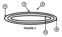
図1及び図2には、本発明による、パイプ・ライナー1を示している。パイプ・ライナー1は、積層された複数の層11から形成された細長いダクト10を有している。積層された複数の層11の各層は、熱可塑性材料からなっている。積層された複数の層11は、図示しない接着剤によって相互に接合されていてもよい。
1 and 2 show a
積層された複数の層11は、全て、相対的に薄い(例えば、1−2mm厚)。そのため、パイプ・ライナー1は、比較的柔軟性を保つことができ、図3及び図4に示すように、実質的に平らな形状2に畳むことができる。形状2では、ダクト10の対向縁部(opposing edges)の曲げ部(folding)4によって、ダクト3の対向する側(opposing sides)は、押し付けられて近接するようになっている。このことによって、パイプ・ライナー1は、従来のパイプ・ライナーよりも容積に関して効率的に保管することができる。特に、畳まれたパイプ・ライナー2は、輸送及び保管のために、リールまたはスピンドルに容易に巻くことが可能である。
All the
図1乃至図4に示したパイプ・ライナー1は、実質的に同心円状のダクトの形態の複数の層11を有しているが、図5に示した好ましい実施の形態では、パイプ・ライナー1は、一連の、反対方向から巻かれたヘリカル・スパイラル(helical spirals)12,13からなっていてもよい。特に、巻きは、編み込み状(woven braid)であってもよい。
Although the
使用時には、ライニングを行うパイプ内にパイプ・ライナー1を挿入する。典型的には、平らな形状2でリールまたはスピンドルからパイプ・ライナー1を展開し、パイプの端部まで、または、パイプの適切な区切り点まで、引っ張る/押し込む。続いて、パイプ・ライナー1を加熱し、パイプの内面に対して押し付け、パイプの内面に対して密着させる。パイプ・ライナー1が冷えると、その位置に固定され、密着したパイプ・ライナーとなる。加熱及び押し付けについては、後ほど詳述する。
At the time of use, the
図6及び図7には、パイプ・ライナー1のさらなる実施の形態を示している。本実施の形態では、パイプ・ライナー1は、積層された複数の層11のうちの2つの層の間に、ケーブル・ダクト13を備えている。ケーブル・ダクト13によって、素早くケーブルを敷設できる。典型的には、パイプ・ライナー1を所定の位置に固定した後、ケーブル・ダクト13に沿ってブローする(blown)ことで敷設する。そのため、パイプ・ライナー1は、パイプをライニングし、且つ、ケーブルにパイプの流路外の安全な場所を提供する。
6 and 7 a further embodiment of the
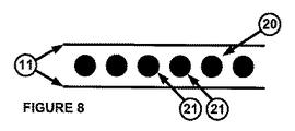
施工中に、十分、且つ、均等にパイプ・ライナー1を加熱するために、パイプ・ライナー1内に加熱手段を備えていてもよい。ある実施の形態では、加熱手段20は、図8に示した複数の導電性フィラメント21を有していてもよい。複数の導電性フィラメント21は、積層された複数の層の間に配置されており、図9に示すように、対向方向(opposing dimensions)に螺旋状に巻かれていてもよい(helically wrapped)。これにより、複数の導電性フィラメント21に電流を流すと、抵抗損(resistive losses)により積層された複数の層11が加熱される。好ましい実施の形態では、図10に示すパルス状電流を流す。パイプ・ライナーの加熱を制御するため、電流パルス30の間の導電性フィラメントの抵抗値を監視する。抵抗値は温度に応じて予定通りに変動するため、加熱している間、流す電流のデューティー比を変えることで、抵抗値の変動によって、パイプ・ライナー1の温度を制御できる。このことは、変化するパルス30の幅と間隔によって、図10に概略的に示してある。
A heating means may be provided in the
図11及び図11aに示したマスター・ユニット31で加熱状態を監視及び制御している。マスター・ユニット31は、パイプ・ライナー1の導電性フィラメント21と電気的に接続するためのコネクタ32を備えている。この例では、コネクタ32は、パイプ・ライナー1の各端部に挿入できるように構成されたドラム部(drum sections)33をさらに備えていてもよい。マスター・ユニット31は、さらに、コネクタ32に電流を流す電力出力手段34と、流した電流の特性を監視し、且つ、特性に対する応答を出力する監視手段36と、監視手段36の出力に応答して電力出力手段34が出力する電流を変更する制御ユニット35をさらに備えている。上述のように、制御ユニット35は、パルス状電流のデューティー比を変化させるように構成されていてもよい。それにもかかわらず、制御ユニット35は、さらに、または、代わりに、電流の大きさを変化させてもよい。さらに、本発明が、パルス状電流の代わりに、定常電流(steady applied current)を流す場合、制御ユニット35は、定常電流の電流の大きさを変化させるように構成されていてもよい。
The heating state is monitored and controlled by the
加熱している間、パイプの内壁に対してパイプ・ライナー1が適切に押し付けられるように、パイプ・ライナー1の各端部にドラム部33を挿入し、実質的な気密シールを形成している。このようにして、ドラム部33の1つに設けられた空気注入口バルブ37からパイプ・ライナーの気密になった部分に空気を注入することができる。十分な加熱及び押し付けの後、その位置でパイプ・ライナーを冷却する。続いて、空気注入口バルブ37を開け、及び/または、ドラム部33を除去する。この方法により、長いパイプ内で、連続する所定の長さのパイプ・ライナー1を施工することができる。施工後、適切な方法(具体的には、プラスチック溶接)を用いて、隣接する所定の長さのパイプ・ライナー1同士を密着させればよい。
A
図8乃至図11に示した導電性フィラメントを使用する例の代わりに、図12に概略的に示すように、加熱手段20は、電磁サセプタ材料、または、複数の磁性粒子を備えていてもよい。サセプタ材料または磁性粒子は、熱可塑性材料からなる積層された複数の層内に含まれていてもよく、熱可塑性材料からなる積層された複数の層の表面コーティングとして提供されてもよく、または、熱可塑性材料からなる積層された複数の層の間に設けられた接着剤内に含まれていてもよい。 As an alternative to the example of using the conductive filaments shown in FIGS. 8-11, the heating means 20 may comprise an electromagnetic susceptor material or a plurality of magnetic particles, as shown schematically in FIG. .. The susceptor material or magnetic particles may be contained within stacked layers of thermoplastic material, may be provided as a surface coating of stacked layers of thermoplastic material, or It may be contained in an adhesive provided between a plurality of laminated layers made of a thermoplastic material.
加熱手段がサセプタ粒子を含む場合、パイプ・ライナー1に対してRF(無線周波数)またはMW(マイクロ波)を放射して加熱を行う。サセプタ材料がRF/MW放射を吸収する。このようにして、サセプタ材料が加熱され、熱伝導によりパイプ・ライナー1に熱が移動する。
When the heating means includes susceptor particles, the
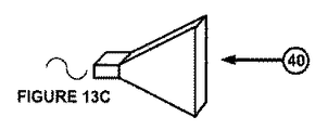
RF/MWは、パイプ・ライナー1内に挿入されるアンテナ40によって放射されてもよい。アンテナ40をパイプ・ライナー1内に挿入し、パイプ・ライナー1に沿って移動させ、押し付けのために/押し付けている間、連続的にパイプ・ライナー1を加熱する。適切なアンテナの形状のいくつかの例を図13に示す。具体的には、四分の一波長アンテナ(図13a)、螺旋コイル(図13b)及びホーン・アンテナ(図13c)である。
The RF/MW may be radiated by the
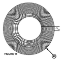
加熱手段が磁性粒子を含む場合、パイプ・ライナー1に対して高周波磁場を印加することで加熱を行う。高周波磁場のヒステリシス損(hysteresis losses)によって磁性粒子が加熱される。そして、熱伝導によりパイプ・ライナー1に熱が移動する。磁性粒子が加熱されてキュリー温度を超えると、磁性粒子は磁性を有さなくなり、印加された高周波磁場による加熱が止まる。積層された複数の層の転移温度に対応するように、磁性粒子のキュリー温度を選択することで、パイプ・ライナー1の加熱を制御することができる。
When the heating means includes magnetic particles, heating is performed by applying a high frequency magnetic field to the
高周波磁場は、パイプ・ライナー1内に挿入されるアンテナ40によって印加されてもよい。アンテナ40をパイプ・ライナー1内に挿入し、パイプ・ライナー1に沿って移動させ、押し付けのために/押し付けている間、連続的にパイプ・ライナー1を加熱する。適切なアンテナの形状の例を図14に示す。具体的には、渦巻きコイルである。
The radio frequency magnetic field may be applied by an
これらの実施の形態におけるパイプ・ライナー1の加熱及び押し付けは、図15に示すような、図11に示した電気的な実施の形態と似た装置で行ってもよい。この例では、再び、ドラム部33によって両端部で所定の長さのパイプ・ライナーを密閉する。空気注入口バルブ37を用いて密閉容積内に空気を注入でき、このことにより、パイプの内壁面にパイプ・ライナー1を押し付けることができる。
The heating and pressing of the
アンテナ40は、ピグ(パイプライン検査計)の密閉部42内に備えられている。ピグ41は、ドラム部33の1つのグランド(gland)38を通る牽引ケーブル(tow cable)43を用いて、パイプ・ライナー1の一端から引っ張り込み、他端まで引っ張ることができる。電力ケーブル44は、他のドラム部33の同等のグランド38を通っている。
The
使用時には、パイプ・ライナー1の一部分は密閉され、内部に空気が注入されている。アンテナ40を作動させ、牽引ケーブル43でパイプ・ライナー内を引っ張る。このことにより、アンテナ40と協働する加熱手段20によってパイプ・ライナー1が加熱され、密閉されたパイプ・ライナー1内の圧力によってパイプに対して押し付けられる。十分な加熱及び押し付けの後、その位置でパイプ・ライナーを冷却する。続いて、空気注入口バルブ37を開け、及び/または、ドラム部33を除去する。この方法により、長いパイプ内で、連続する所定の長さのパイプ・ライナー1を施工することができる。施工後、適切な方法(具体的には、プラスチック溶接)を用いて、隣接する所定の長さのパイプ・ライナー1同士を密着させればよい。
At the time of use, a part of the
このような実施の形態においては、ピグ41は、パイプ・ライナー1を外方向に押すように構成された、1以上の弾性プレート45をさらに備えていてもよい。このような実施の形態では、ドラム部33を省いて、加熱されたパイプ・ライナー1の押し付けを弾性プレート45単体に頼るようにしてもよい。
In such an embodiment, the
加熱手段20がサセプタ材料である実施の形態では、ピグは、赤外線センサ(図示せず)をさらに備えていてもよい。赤外線センサは、パイプ・ライナー1の温度を決定するように構成されていてもよく、温度に応じてアンテナ40の出力を変化させるようにしてもよい。
In embodiments where the heating means 20 is a susceptor material, the pig may further comprise an infrared sensor (not shown). The infrared sensor may be configured to determine the temperature of the
上記実施の形態は例示としてのみ示されている。添付の請求の範囲に規定されている発明の範囲を逸脱することなく、多くの変形例が可能である。 The above embodiments are given as examples only. Many variations are possible without departing from the scope of the invention as defined in the appended claims.
Claims (10)
前記パイプ・ライナーは、熱可塑性材料からなる積層された複数の層から形成された細長いダクトを備えており、
前記パイプ・ライナー内には、加熱手段が備えられており、
前記パイプ・ライナーは、2つの積層された層の間に設けられたケーブル・ダクトを有しており、
前記ケーブル・ダクトは、前記積層された複数の層を形成する前記熱可塑性材料よりも高い転移温度を有する熱可塑性材料から形成されていることを特徴とするパイプ・ライナー。 A pipe liner used when repairing and/or regenerating a pipe,
The pipe liner comprises an elongated duct formed of a plurality of laminated layers of thermoplastic material,
A heating means is provided in the pipe liner ,
The pipe liner has a cable duct provided between two laminated layers,
The pipe liner , wherein the cable duct is formed from a thermoplastic material having a higher transition temperature than the thermoplastic material forming the laminated layers .
パイプ内に前記パイプ・ライナーを挿入する挿入ステップと、
前記パイプ・ライナーを加熱する加熱ステップと、
次に、前記パイプの内面に対して、前記パイプ・ライナーを押し付ける押付ステップとを含み、
前記パイプ・ライナーは、ケーブル・ダクトを有するようになっており、
前記ケーブル・ダクトに沿って、ケーブルを敷設するステップを含むことを特徴とするパイプ・ライナーの施工方法。 A method for constructing a pipe liner of a type having an elongated duct formed of a plurality of laminated layers made of a thermoplastic material and having heating means inside thereof
An inserting step of inserting the pipe liner into the pipe,
A heating step of heating the pipe liner,
Then, the inner surface of the pipe, viewed contains a pressing step of pressing the pipe liner,
The pipe liner has a cable duct,
Along said cable duct, construction method of a pipe liner according to claim containing Mukoto the step of laying the cable.
前記加熱ステップは、前記複数の導電性フィラメントに電流を流して実行される請求項7に記載のパイプ・ライナーの施工方法。 The heating means has a plurality of conductive filaments,
The pipe liner construction method according to claim 7 , wherein the heating step is performed by passing an electric current through the plurality of conductive filaments.
前記加熱ステップは、前記パイプ・ライナーに対して、無線周波数(RF)またはマイクロ波(MW)を放射にすることよって実行される請求項7に記載のパイプ・ライナーの施工方法。 The heating means includes a susceptor material,
The method for applying a pipe liner according to claim 7 , wherein the heating step is performed by radiating radio frequency (RF) or microwave (MW) to the pipe liner.
前記加熱ステップは、前記パイプ・ライナーに対して、高周波磁場を印加することによって実行される請求項7に記載のパイプ・ライナーの施工方法。
The heating means includes a plurality of magnetic particles adjusted to have a Curie temperature corresponding to a transition temperature of the laminated layers,
The pipe liner construction method according to claim 7 , wherein the heating step is performed by applying a high-frequency magnetic field to the pipe liner.
Applications Claiming Priority (3)
| Application Number | Priority Date | Filing Date | Title |
|---|---|---|---|
| GB1411889.7 | 2014-07-03 | ||
| GB1411889.7A GB2527821B (en) | 2014-07-03 | 2014-07-03 | Improvements in or in relation to pipe liners and the installation thereof |
| PCT/GB2015/051917 WO2016001659A1 (en) | 2014-07-03 | 2015-06-30 | Improvements in or in relation to pipe liners and the installation thereof |
Publications (3)
| Publication Number | Publication Date |
|---|---|
| JP2017530039A JP2017530039A (en) | 2017-10-12 |
| JP2017530039A5 JP2017530039A5 (en) | 2018-07-19 |
| JP6725500B2 true JP6725500B2 (en) | 2020-07-22 |
Family
ID=51410595
Family Applications (1)
| Application Number | Title | Priority Date | Filing Date |
|---|---|---|---|
| JP2017520019A Active JP6725500B2 (en) | 2014-07-03 | 2015-06-30 | Improvement of pipe liner or improvement of pipe liner and construction of these |
Country Status (9)
| Country | Link |
|---|---|
| US (1) | US10359143B2 (en) |
| EP (1) | EP3164635B8 (en) |
| JP (1) | JP6725500B2 (en) |
| AU (1) | AU2015282478B2 (en) |
| BR (1) | BR112016031019B1 (en) |
| GB (1) | GB2527821B (en) |
| NZ (1) | NZ728620A (en) |
| WO (1) | WO2016001659A1 (en) |
| ZA (1) | ZA201700756B (en) |
Families Citing this family (8)
| Publication number | Priority date | Publication date | Assignee | Title |
|---|---|---|---|---|
| WO2016144238A1 (en) * | 2015-03-06 | 2016-09-15 | Climate Recovery Ind Ab | Method and apparatus for introducing a foil into an elongated duct and apparatus and method for laminating a foil to a duct |
| GB2550428A (en) * | 2016-05-20 | 2017-11-22 | Oranmore Env Services Ltd | Pipe repair composition and method |
| GB2571540B (en) | 2018-02-28 | 2020-10-28 | Craley Group Ltd | Improvements in or relating to the monitoring of fluid pipes |
| WO2020028239A1 (en) * | 2018-07-30 | 2020-02-06 | Essentium Inc. | High frequency adhesive bonding |
| DE102019100276A1 (en) | 2018-08-22 | 2020-02-27 | DCF Holding GmbH | Method and device for the rehabilitation of a pipe section of a pipeline system |
| DK3614032T3 (en) * | 2018-08-22 | 2023-05-01 | DCF Holding GmbH | APPARATUS AND METHOD FOR SANITATING A PIPE SECTION IN A PIPELINE SYSTEM |
| EP3839320A1 (en) * | 2019-12-18 | 2021-06-23 | Bodus GmbH | System for curing and / or testing a pipe liner and method for curing and / or inspecting a pipe liner |
| DE102021107399A1 (en) | 2021-03-24 | 2022-09-29 | I.S.T. Innovative Sewer Technologies Gmbh | Liner tube, curing apparatus, system and method for trenchless sewer rehabilitation |
Family Cites Families (17)
| Publication number | Priority date | Publication date | Assignee | Title |
|---|---|---|---|---|
| US3511734A (en) | 1963-11-01 | 1970-05-12 | Cee Bee Mfg Co Inc | Method of lining concrete pipe |
| US4067765A (en) * | 1976-09-17 | 1978-01-10 | William C. Heller, Jr. | Susceptor based bonding technique for plastic material utilizing oleaginous substance at the bonding interface |
| US4521659A (en) * | 1979-08-24 | 1985-06-04 | The United States Of America As Represented By The Administrator Of The National Aeronautics & Space Administration | Induction heating gun |
| FR2542416B1 (en) * | 1983-03-11 | 1985-06-14 | Vernhes Frederic | SELF-CONDUCTING SHEATHES FOR CONDUITS AND METHOD FOR INTRODUCING AND POSITIONING SUCH SHEATHES IN A DUCT |
| US4978825A (en) | 1989-11-08 | 1990-12-18 | Northrop Corporation | Thermoplastic composite induction welder |
| GB9009899D0 (en) * | 1990-05-02 | 1990-06-27 | Du Pont Canada | Lining of metallic pipe |
| US5248864A (en) | 1991-07-30 | 1993-09-28 | E. I. Du Pont De Nemours And Company | Method for induction heating of composite materials |
| EP0551790A1 (en) | 1992-01-17 | 1993-07-21 | David Campbell Mitchell | A method of curing a heat curable substance contained in a pipe liner and apparatus and pipe liner for carrying out this method |
| WO1996011783A1 (en) * | 1994-10-14 | 1996-04-25 | Sound Pipe Limited | Methods for and machines for use in the lining of pipelines and passageways |
| WO1996012605A1 (en) * | 1994-10-24 | 1996-05-02 | Sound Pipe Ltd | Improvements relating to lining of pipelines and passageways |
| US5487411A (en) * | 1994-11-22 | 1996-01-30 | Ipex Inc. | Liner pipe for repair of a host pipe |
| US5606997A (en) * | 1995-04-28 | 1997-03-04 | Advance Trenchless Rehabilitation Systems | Method for rehabilitating pipe line and resin impregnated lining having an integral heating element |
| US6935376B1 (en) * | 1998-07-28 | 2005-08-30 | Safetyliner Systems, Llc | Enhancement of profiled tubular lining systems by channel augmentation |
| AU2001268175A1 (en) | 2000-06-05 | 2001-12-17 | Milliken And Company | Novel textile reinforced thermoplastic or thermoset pipes and methods of making thereof |
| US6311730B2 (en) * | 2000-10-05 | 2001-11-06 | G. Gregory Penza | Communications conduit installation method and conduit-containing product suitable for use therein |
| US20070267785A1 (en) * | 2004-03-18 | 2007-11-22 | Bellamy Norman W | Composite Pipe Lining and Method and Apparatus for Installing a Composite Lining |
| EP2273171B1 (en) | 2004-12-13 | 2018-09-05 | Smart Pipe Company, LP. | Method of measuring a leak in a pipe |
-
2014
- 2014-07-03 GB GB1411889.7A patent/GB2527821B/en active Active
-
2015
- 2015-06-30 NZ NZ728620A patent/NZ728620A/en unknown
- 2015-06-30 AU AU2015282478A patent/AU2015282478B2/en active Active
- 2015-06-30 US US15/321,608 patent/US10359143B2/en active Active
- 2015-06-30 EP EP15744634.5A patent/EP3164635B8/en active Active
- 2015-06-30 JP JP2017520019A patent/JP6725500B2/en active Active
- 2015-06-30 WO PCT/GB2015/051917 patent/WO2016001659A1/en active Application Filing
- 2015-06-30 BR BR112016031019-5A patent/BR112016031019B1/en active IP Right Grant
-
2017
- 2017-01-31 ZA ZA2017/00756A patent/ZA201700756B/en unknown
Also Published As
| Publication number | Publication date |
|---|---|
| WO2016001659A1 (en) | 2016-01-07 |
| NZ728620A (en) | 2022-10-28 |
| JP2017530039A (en) | 2017-10-12 |
| BR112016031019A2 (en) | 2018-12-18 |
| US10359143B2 (en) | 2019-07-23 |
| US20170159869A1 (en) | 2017-06-08 |
| ZA201700756B (en) | 2018-04-25 |
| EP3164635B1 (en) | 2020-12-02 |
| GB201411889D0 (en) | 2014-08-20 |
| EP3164635B8 (en) | 2021-01-13 |
| EP3164635A1 (en) | 2017-05-10 |
| GB2527821B (en) | 2017-05-03 |
| BR112016031019B1 (en) | 2021-11-16 |
| GB2527821A (en) | 2016-01-06 |
| AU2015282478A1 (en) | 2017-02-23 |
| AU2015282478B2 (en) | 2020-04-30 |
Similar Documents
| Publication | Publication Date | Title |
|---|---|---|
| JP6725500B2 (en) | Improvement of pipe liner or improvement of pipe liner and construction of these | |
| US7523764B2 (en) | Method and apparatus for spot repair of pipe | |
| JP4076188B2 (en) | Method for joining thermoplastic composite products and pipe works | |
| US7934311B2 (en) | Methods of manufacturing electrical cables | |
| CN103459128B (en) | The electromagnetic induction welding of plastic tube distributing system | |
| JP2017530039A5 (en) | ||
| PT818125E (en) | INDUCTION HEATING SYSTEM FOR FUSEO LIGACATIONS | |
| RU2248491C2 (en) | Method and device for assembling cylindrical pipeline in trench having opened top | |
| US20190016021A1 (en) | Apparatus for curing a tubular liner | |
| TW200428414A (en) | Method and apparatus for manufacturing coaxial cable with composite inner conductor | |
| CN102356263A (en) | Convoluted coated braided hose assembly and method of making same | |
| US9435710B2 (en) | Lining tube and method for checking the curing through of a lining tube of resin-impregnated fiber material | |
| JP2010162749A (en) | Method for manufacturing pipe-lining material | |
| GB2034433A (en) | Method of hose production and product | |
| US20040219317A1 (en) | Process for manufacturing a flexible tubular pipe having extruded layers made of crosslinked polyethylene | |
| US20040144471A1 (en) | Method for producing a cable | |
| EP3699474A1 (en) | Method for repairing and/or reinforcing a pipe segment | |
| KR101431160B1 (en) | Apparatus of controlling electric power for electric fusion pipe fitting using conductive polymer composite and method thereof | |
| KR20230001541A (en) | Method for insulation system restoration of a power cable | |
| EA021200B1 (en) | Method for coating a joint between two pipes | |
| KR20160125907A (en) | Power cable and manufacturing method of the same | |
| EP1626220A1 (en) | Method and system for lining a pipe with a heat-curable lining | |
| EP4113762A1 (en) | Pressurisation and heating device and method for insulation system restoration of a power cable | |
| KR20080057795A (en) | Structure for molding pipe | |
| WO1998021802A1 (en) | Helical spiral closure with bondline sealing |
Legal Events
| Date | Code | Title | Description |
|---|---|---|---|
| A521 | Request for written amendment filed |
Free format text: JAPANESE INTERMEDIATE CODE: A523 Effective date: 20180606 |
|
| A621 | Written request for application examination |
Free format text: JAPANESE INTERMEDIATE CODE: A621 Effective date: 20180606 |
|
| A977 | Report on retrieval |
Free format text: JAPANESE INTERMEDIATE CODE: A971007 Effective date: 20190522 |
|
| A131 | Notification of reasons for refusal |
Free format text: JAPANESE INTERMEDIATE CODE: A131 Effective date: 20190611 |
|
| A601 | Written request for extension of time |
Free format text: JAPANESE INTERMEDIATE CODE: A601 Effective date: 20190910 |
|
| A601 | Written request for extension of time |
Free format text: JAPANESE INTERMEDIATE CODE: A601 Effective date: 20191108 |
|
| A521 | Request for written amendment filed |
Free format text: JAPANESE INTERMEDIATE CODE: A523 Effective date: 20191211 |
|
| TRDD | Decision of grant or rejection written | ||
| A01 | Written decision to grant a patent or to grant a registration (utility model) |
Free format text: JAPANESE INTERMEDIATE CODE: A01 Effective date: 20200526 |
|
| A61 | First payment of annual fees (during grant procedure) |
Free format text: JAPANESE INTERMEDIATE CODE: A61 Effective date: 20200625 |
|
| R150 | Certificate of patent or registration of utility model |
Ref document number: 6725500 Country of ref document: JP Free format text: JAPANESE INTERMEDIATE CODE: R150 |
|
| R250 | Receipt of annual fees |
Free format text: JAPANESE INTERMEDIATE CODE: R250 |