JP6720063B2 - Image processing device, imaging device, and display system - Google Patents

Image processing device, imaging device, and display system Download PDF

Info

Publication number
JP6720063B2
JP6720063B2 JP2016226334A JP2016226334A JP6720063B2 JP 6720063 B2 JP6720063 B2 JP 6720063B2 JP 2016226334 A JP2016226334 A JP 2016226334A JP 2016226334 A JP2016226334 A JP 2016226334A JP 6720063 B2 JP6720063 B2 JP 6720063B2
Authority
JP
Japan
Prior art keywords
image
marker
detection target
control unit
display
Prior art date
Legal status (The legal status is an assumption and is not a legal conclusion. Google has not performed a legal analysis and makes no representation as to the accuracy of the status listed.)
Active
Application number
JP2016226334A
Other languages
Japanese (ja)
Other versions
JP2018085582A (en
Inventor
朋弘 嶋津
朋弘 嶋津
太郎 深沢
太郎 深沢
Current Assignee (The listed assignees may be inaccurate. Google has not performed a legal analysis and makes no representation or warranty as to the accuracy of the list.)
Kyocera Corp
Original Assignee
Kyocera Corp
Priority date (The priority date is an assumption and is not a legal conclusion. Google has not performed a legal analysis and makes no representation as to the accuracy of the date listed.)
Filing date
Publication date
Application filed by Kyocera Corp filed Critical Kyocera Corp
Priority to JP2016226334A priority Critical patent/JP6720063B2/en
Priority to EP17871828.4A priority patent/EP3544293B1/en
Priority to US16/462,488 priority patent/US11030468B2/en
Priority to PCT/JP2017/041900 priority patent/WO2018092919A1/en
Publication of JP2018085582A publication Critical patent/JP2018085582A/en
Application granted granted Critical
Publication of JP6720063B2 publication Critical patent/JP6720063B2/en
Active legal-status Critical Current
Anticipated expiration legal-status Critical

Links

Images

Description

本開示は、画像処理装置、撮像装置、および表示システムに関する。 The present disclosure relates to an image processing device, an imaging device, and a display system.

従来、例えば車両等の移動体の外部領域の映像を表示する技術が知られている。例えば、特許文献1には、車両に備えられたカメラの映像を表示するモニタへの電源供給を制御する技術が開示されている。 Conventionally, there is known a technique of displaying an image of an external area of a moving body such as a vehicle. For example, Patent Document 1 discloses a technique of controlling power supply to a monitor that displays an image of a camera provided in a vehicle.

特開2009−40113号公報JP, 2009-40113, A

従来、移動体の外部領域の映像を表示する技術について改善の余地があった。 Conventionally, there has been room for improvement in the technology for displaying an image of an external area of a mobile body.

本開示は、移動体の外部領域の映像を表示する技術の利便性を向上させる画像処理装置、撮像装置、および表示システムに関する。 The present disclosure relates to an image processing device, an imaging device, and a display system that improve the convenience of technology for displaying an image in an external area of a moving body.

本開示の一実施形態に係る画像処理装置は、通信部と、制御部と、を備える。通信部は、移動体の外部領域を撮像した第1映像を取得する。制御部は、第1映像上の表示領域に対応する第2映像を表示装置に表示させる。制御部は、第1映像上の検出領域において検出対象の少なくとも一部を検出し、検出対象の前記少なくとも一部が検出された第1映像上の検出位置が、表示領域の外側且つ検出領域の内側にあり、かつ移動体と検出対象との間の距離が減少する場合、距離の減少に対して移動体と検出対象との何れの寄与が大きいか判定し、移動体の寄与が大きいと判定した場合、検出対象に対応するマーカの少なくとも一部が前記第2映像上で第1方向に移動するように、マーカを第2映像に重畳して表示装置に表示させ、検出対象の寄与が大きいと判定した場合、マーカの少なくとも一部が第2映像上で第2方向に移動するように、マーカを第2映像に重畳して表示装置に表示させる。 An image processing device according to an embodiment of the present disclosure includes a communication unit and a control unit. The communication unit acquires a first video imaged of the external area of the mobile body. The control unit causes the display device to display the second image corresponding to the display area on the first image. The control unit detects at least a part of the detection target in the detection area on the first video, and the detection position on the first video where the at least a part of the detection target is detected is outside the display area and within the detection area. Ri inside near, and if the distance between the moving entity and the detection target is reduced, any contribution of the moving body and the detection target with respect to the distance reduction or determined larger, the larger the contribution of the mobile When determined, the marker is superimposed on the second video and displayed on the display device so that at least a part of the marker corresponding to the detection target moves in the first direction on the second video, and the contribution of the detection target is When it is determined that the marker is large, the marker is superimposed on the second image and displayed on the display device so that at least a part of the marker moves in the second direction on the second image.

本開示の一実施形態に係る撮像装置は、撮像素子と、制御部と、を備える。撮像素子は、移動体の外部領域を撮像した第1映像を生成する。制御部は、第1映像上の表示領域に対応する第2映像を表示装置に表示させる。制御部は、第1映像上の検出領域において検出対象の少なくとも一部を検出し、検出対象の少なくとも一部が検出された第1映像上の検出位置が、表示領域の外側且つ検出領域の内側にあり、かつ前記移動体と前記検出対象との間の距離が減少する場合、前記距離の減少に対して前記移動体と前記検出対象との何れの寄与が大きいか判定し、前記移動体の寄与が大きいと判定した場合、前記検出対象に対応するマーカの少なくとも一部が前記第2映像上で第1方向に移動するように、前記マーカを前記第2映像に重畳して前記表示装置に表示させ、前記検出対象の寄与が大きいと判定した場合、前記マーカの前記少なくとも一部が前記第2映像上で第2方向に移動するように、マーカを第2映像に重畳して表示装置に表示させる。 An imaging device according to an embodiment of the present disclosure includes an imaging element and a control unit. The image pickup element generates a first image obtained by picking up an image of the external area of the moving body. The control unit causes the display device to display the second image corresponding to the display area on the first image. The control unit detects at least a part of the detection target in the detection area on the first video, and the detection position on the first video where at least a part of the detection target is detected is outside the display area and inside the detection area. near is, and when said distance between the moving member and the detection target is decreased, to determine any or large contribution of the detection target and the moving object relative to a decrease in the distance, the moving object When it is determined that the contribution of the marker is large, the marker is superimposed on the second image so that at least a part of the marker corresponding to the detection target moves in the first direction on the second image, the display device. is displayed, if it is determined that the contribution of the detection target is large, so that at least a portion of the marker is moved in the second direction on the second image, by superimposing the M a Ca to a second video Display on the display device.

本開示の一実施形態に係る表示システムは、表示装置と、撮像装置と、画像処理装置と、を備える。撮像装置は、移動体の外部領域を撮像した第1映像を生成する。画像処理装置は、第1映像上の表示領域に対応する第2映像を表示装置に表示させる。画像処理装置は、第1映像上の検出領域において検出対象の少なくとも一部を検出し、検出対象の少なくとも一部が検出された第1映像上の検出位置が、表示領域の外側且つ検出領域の内側にあり、かつ前記移動体と前記検出対象との間の距離が減少する場合、前記距離の減少に対して前記移動体と前記検出対象との何れの寄与が大きいか判定し、前記移動体の寄与が大きいと判定した場合、前記検出対象に対応するマーカの少なくとも一部が前記第2映像上で第1方向に移動するように、前記マーカを前記第2映像に重畳して前記表示装置に表示させ、前記検出対象の寄与が大きいと判定した場合、前記マーカの前記少なくとも一部が前記第2映像上で第2方向に移動するように、マーカを第2映像に重畳して表示装置に表示させる。 A display system according to an embodiment of the present disclosure includes a display device, an imaging device, and an image processing device. The imaging device generates a first video image of the external area of the moving body. The image processing device causes the display device to display the second image corresponding to the display area on the first image. The image processing device detects at least a part of the detection target in the detection area on the first video, and the detection position on the first video where at least a part of the detection target is detected is outside the display area and within the detection area. Ri inside near, and the case where the distance between the moving member and the detection target is decreased, to determine any or large contribution of the detection target and the moving object relative to a decrease in the distance, the moving When it is determined that the contribution of the body is large, the marker is superimposed on the second video so that at least a part of the marker corresponding to the detection target moves in the first direction on the second video, and the display is performed. device to be displayed, if it is determined that the contribution of the detection target is large, so that at least a portion of the marker is moved in the second direction on the second image, by superimposing the M a Ca to a second video Display on the display device.

本開示の一実施形態に係る画像処理装置、撮像装置、および表示システムよれば、移動体の外部領域の映像を表示する技術の利便性が向上する。 According to the image processing device, the imaging device, and the display system according to the embodiment of the present disclosure, the convenience of the technique for displaying the image of the external area of the moving body is improved.

本発明の一実施形態に係る表示システムの概略構成を示すブロック図である。It is a block diagram showing a schematic structure of a display system concerning one embodiment of the present invention. 表示システムを備える車両を左側方から見た図である。It is the figure which looked at the vehicle provided with the display system from the left side. 第1映像の第1例を示す図である。It is a figure which shows the 1st example of a 1st image. 図3の第1映像の表示領域に対応する第2映像の第1例を示す図である。FIG. 4 is a diagram showing a first example of a second video image corresponding to the display area of the first video image of FIG. 3. 検出対象に重畳される第3マーカの例を示す図である。It is a figure which shows the example of the 3rd marker superimposed on a detection target. 検出対象の周囲に表示される第1マーカおよび第2マーカの第1例を示す図である。It is a figure which shows the 1st example of the 1st marker and 2nd marker displayed around the detection target. 検出対象の周囲に表示される第1マーカおよび第2マーカの第2例を示す図である。It is a figure which shows the 2nd example of the 1st marker and 2nd marker displayed around the detection target. 検出対象の周囲に表示される第1マーカおよび第2マーカの第3例を示す図である。It is a figure which shows the 3rd example of the 1st marker and 2nd marker displayed around the detection target. 第1映像の第2例を示す図である。It is a figure which shows the 2nd example of a 1st image. 図9の第1映像の表示領域に対応する第2映像の第2例を示す図である。It is a figure which shows the 2nd example of the 2nd image corresponding to the display area of the 1st image of FIG. 第1映像の第3例を示す図である。It is a figure which shows the 3rd example of a 1st image. 図11の第1映像の表示領域に対応する第2映像の第3例を示す図である。It is a figure which shows the 3rd example of the 2nd image corresponding to the display area of the 1st image of FIG. 第1映像の第4例を示す図である。It is a figure which shows the 4th example of a 1st image|video. 図13の第1映像の表示領域に対応する第2映像の第4例を示す図である。It is a figure which shows the 4th example of the 2nd image corresponding to the display area of the 1st image of FIG. 第1映像の第5例を示す図である。It is a figure which shows the 5th example of a 1st image. 図15の第1映像の表示領域に対応する第2映像の第5例を示す図である。It is a figure which shows the 5th example of the 2nd image corresponding to the display area of the 1st image of FIG. 図15の第1映像の表示領域に対応する第2映像の他の例を示す図である。It is a figure which shows the other example of the 2nd image corresponding to the display area of the 1st image of FIG.

以下、本発明の実施形態について、図面を参照して説明する。 Hereinafter, embodiments of the present invention will be described with reference to the drawings.

(表示システム)
図1を参照して、本発明の一実施形態に係る表示システム10について説明する。
(Display system)
A display system 10 according to an embodiment of the present invention will be described with reference to FIG.

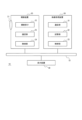
図1に示すように、表示システム10は、撮像装置20と、画像処理装置30と、表示装置40と、を備える。撮像装置20表示システム10の各構成要素は、例えばネットワーク51を介して情報を送受信可能である。ネットワーク51は、例えば無線、有線、またはCAN(Controller Area Network)等を含んでよい。 As shown in FIG. 1, the display system 10 includes an imaging device 20, an image processing device 30, and a display device 40. Each component of the display system 10 of the imaging device 20 can send and receive information via the network 51, for example. The network 51 may include, for example, wireless, wired, CAN (Controller Area Network), or the like.

他の実施形態において、表示システム10の一部または全部の構成要素が、1つの装置として一体的に構成されてよい。例えば、撮像装置20または表示装置40に、画像処理装置30撮像装置20を内蔵させる構成等が考えられる。 In other embodiments, some or all of the components of the display system 10 may be integrally configured as one device. For example, a configuration in which the image pickup device 20 or the display device 40 includes the image pickup device 20 of the image processing device 30 may be considered.

図2に示すように、撮像装置20、画像処理装置30、および表示装置40は、移動体50に備えられてよい。本開示における「移動体」は、例えば車両、船舶、および航空機等を含んでよい。車両は、例えば自動車、産業車両、鉄道車両、生活車両、および滑走路を走行する固定翼機等を含んでよい。自動車は、例えば乗用車、トラック、バス、二輪車、およびトロリーバス等を含んでよい。産業車両は、例えば農業および建設向けの産業車両等を含んでよい。産業車両は、例えばフォークリフトおよびゴルフカート等を含んでよい。農業向けの産業車両は、例えばトラクター、耕耘機、移植機、バインダー、コンバイン、および芝刈り機等を含んでよい。建設向けの産業車両は、例えばブルドーザー、スクレーバー、ショベルカー、クレーン車、ダンプカー、およびロードローラ等を含んでよい。車両は、人力で走行するものを含んでよい。車両の分類は、上述した例に限られない。例えば、自動車は、道路を走行可能な産業車両を含んでよい。複数の分類に同じ車両が含まれてよい。船舶は、例えばマリンジェット、ボート、およびタンカー等を含んでよい。航空機は、例えば固定翼機および回転翼機等を含んでよい。 As shown in FIG. 2, the imaging device 20, the image processing device 30, and the display device 40 may be included in the moving body 50. The “moving body” in the present disclosure may include, for example, a vehicle, a ship, an aircraft, and the like. The vehicle may include, for example, an automobile, an industrial vehicle, a railroad vehicle, a living vehicle, and a fixed-wing aircraft traveling on a runway. Vehicles may include, for example, passenger cars, trucks, buses, motorcycles, trolleybuses, and the like. Industrial vehicles may include, for example, industrial vehicles for agriculture and construction. Industrial vehicles may include, for example, forklifts and golf carts and the like. Industrial vehicles for agriculture may include, for example, tractors, tillers, transplanters, binders, combines, lawn mowers and the like. Industrial vehicles for construction may include, for example, bulldozers, scrapers, excavators, mobile cranes, dump trucks, road rollers, and the like. Vehicles may include those that are manually driven. The classification of vehicles is not limited to the example described above. For example, an automobile may include an industrial vehicle that can travel on a road. The same vehicle may be included in multiple classifications. Vessels may include, for example, marine jets, boats, tankers, and the like. Aircraft may include, for example, fixed-wing aircraft, rotary-wing aircraft, and the like.

撮像装置20は、移動体50の外部領域を撮像可能である。撮像装置20の位置は、移動体50の内部および外部において任意である。例えば図2に示すように、撮像装置20は、移動体50の後方の外部領域を撮像可能な移動体50の後方に位置する。画像処理装置30の位置は、移動体50内において任意である。表示装置40は、対象者60によって視認可能である。表示装置40の位置は、移動体50において任意である。例えば図2に示すように、表示装置40は、移動体50のダッシュボードの中に位置する。 The imaging device 20 can capture an image of the area outside the moving body 50. The position of the imaging device 20 is arbitrary inside and outside the moving body 50. For example, as shown in FIG. 2, the imaging device 20 is located behind the moving body 50 capable of picking up an image of the external area behind the moving body 50. The position of the image processing device 30 is arbitrary in the moving body 50. The display device 40 can be visually recognized by the target person 60. The position of the display device 40 is arbitrary in the moving body 50. For example, as shown in FIG. 2, the display device 40 is located inside the dashboard of the moving body 50.

(撮像装置)
撮像装置20について詳細に説明する。例えば図1に示すように、撮像装置20は、撮像光学系21と、撮像素子22と、通信部23と、制御部24とを備える。
(Imaging device)
The imaging device 20 will be described in detail. For example, as shown in FIG. 1, the imaging device 20 includes an imaging optical system 21, an imaging element 22, a communication unit 23, and a control unit 24.

撮像光学系21は、被写体像を結像させる。例えば、撮像光学系21は、絞りおよび1つ以上のレンズを含んでよい。 The imaging optical system 21 forms a subject image. For example, the imaging optics 21 may include a diaphragm and one or more lenses.

撮像素子22は、2次元配列された複数の画素を有する。撮像素子22は、例えばCCD(Charge Coupled Device)撮像素子またはCMOS(Complementary Metal Oxide Semiconductor)撮像素子を含んでよい。撮像素子22は、撮像光学系21によって結像される被写体像を撮像して、撮像画像を生成可能である。 The image sensor 22 has a plurality of pixels arranged two-dimensionally. The image pickup device 22 may include, for example, a CCD (Charge Coupled Device) image pickup device or a CMOS (Complementary Metal Oxide Semiconductor) image pickup device. The image pickup element 22 can pick up a subject image formed by the image pickup optical system 21 and generate a picked-up image.

通信部23は、外部装置と通信可能な通信インタフェースを含んでよい。通信部23は、ネットワーク51を介して情報の送受信が可能であってよい。外部装置は、例えば画像処理装置30を含んでよい。本開示における「通信インタフェース」は、例えば物理コネクタ、および無線通信機を含んでよい。物理コネクタは、電気信号による伝送に対応した電気コネクタ、光信号による伝送に対応した光コネクタ、および電磁波による伝送に対応した電磁コネクタを含んでよい。電気コネクタは、IEC60603に準拠するコネクタ、USB規格に準拠するコネクタ、RCA端子に対応するコネクタ、EIAJ CP−1211Aに規定されるS端子に対応するコネクタ、EIAJ RC−5237に規定されるD端子に対応するコネクタ、HDMI(登録商標)規格に準拠するコネクタ、およびBNC(British Naval ConnectorまたはBaby-series N Connector等)を含む同軸ケーブルに対応するコネクタを含んでよい。光コネクタは、IEC 61754に準拠する種々のコネクタを含んでよい。無線通信機は、Bluetooth(登録商標)、およびIEEE802.11を含む各規格に準拠する無線通信機を含んでよい。無線通信機は、少なくとも1つのアンテナを含む。 The communication unit 23 may include a communication interface capable of communicating with an external device. The communication unit 23 may be capable of transmitting and receiving information via the network 51. The external device may include, for example, the image processing device 30. The “communication interface” in the present disclosure may include, for example, a physical connector and a wireless communication device. The physical connector may include an electrical connector compatible with transmission of electric signals, an optical connector compatible with transmission of optical signals, and an electromagnetic connector compatible with transmission of electromagnetic waves. The electrical connector is a connector compliant with IEC60603, a connector compliant with USB standard, a connector corresponding to RCA terminal, a connector corresponding to S terminal defined in EIAJ CP-1211A, and a D terminal defined in EIAJ RC-5237. Corresponding connectors, connectors conforming to the HDMI (registered trademark) standard, and connectors corresponding to coaxial cables including BNC (British Naval Connector or Baby-series N Connector etc.) may be included. Optical connectors may include various connectors according to IEC 61754. The wireless communication device may include a wireless communication device compliant with each standard including Bluetooth (registered trademark) and IEEE 802.11. The wireless communicator includes at least one antenna.

制御部24は、1つ以上のプロセッサを含む。本開示における「プロセッサ」は、特定の処理に特化した専用のプロセッサ、および特定のプログラムを読み込むことによって特定の機能を実行する汎用のプロセッサを含んでよい。専用のプロセッサには、DSP(Digital Signal Processor)および特定用途向けIC(ASIC;Application Specific Integrated Circuit)が含まれてよい。プロセッサには、プログラマブルロジックデバイス(PLD;Programmable Logic Device)が含まれてよい。PLDには、FPGA(Field-Programmable Gate Array)が含まれてよい。制御部24は、1つまたは複数のプロセッサが協働するSoC(System-on-a-Chip)、およびSiP(System In a Package)のいずれかであってよい。 The control unit 24 includes one or more processors. The “processor” in the present disclosure may include a dedicated processor specialized for a specific process, and a general-purpose processor that executes a specific function by reading a specific program. The dedicated processor may include a DSP (Digital Signal Processor) and an application-specific integrated circuit (ASIC). The processor may include a programmable logic device (PLD). The PLD may include an FPGA (Field-Programmable Gate Array). The control unit 24 may be one of a SoC (System-on-a-Chip) in which one or more processors cooperate, and a SiP (System In a Package).

制御部24は、撮像装置20全体の動作を制御する。制御部24は、任意のフレームレートで、撮像素子22に撮像画像を生成させてよい。当該フレームレートは、例えば、表示装置40が表示可能なフレームレートに略一致してよい。制御部24は、生成された撮像画像に対して、所定の画像処理を実行してよい。当該画像処理は、例えば露出調整処理、ホワイトバランス処理、および歪み補正処理等を含んでよい。制御部24は、通信部23を介して画像処理装置30へ、撮像画像を出力する。例えば、制御部24は、上述のフレームレートで撮像画像を順次に出力してよい。以下、上述のフレームレートで出力される各撮像画像を、単にフレームともいう。撮像装置20から出力される当該複数の撮像画像を、第1映像ともいう。例えばフレームレートが60fps(Flame per Seconds)である場合、1秒あたり60枚の撮像画像が第1映像として出力される。 The control unit 24 controls the operation of the entire imaging device 20. The control unit 24 may cause the image sensor 22 to generate a captured image at an arbitrary frame rate. The frame rate may substantially match the frame rate that the display device 40 can display, for example. The control unit 24 may perform predetermined image processing on the generated captured image. The image processing may include, for example, exposure adjustment processing, white balance processing, distortion correction processing, and the like. The control unit 24 outputs the captured image to the image processing device 30 via the communication unit 23. For example, the control unit 24 may sequentially output the captured images at the above frame rate. Hereinafter, each captured image output at the above frame rate is also simply referred to as a frame. The plurality of captured images output from the imaging device 20 are also referred to as a first video. For example, when the frame rate is 60 fps (Flame per Seconds), 60 captured images per second are output as the first video.

(画像処理装置)
画像処理装置30について詳細に説明する。画像処理装置30は、通信部31と、記憶部32と、制御部33とを備える。
(Image processing device)
The image processing device 30 will be described in detail. The image processing device 30 includes a communication unit 31, a storage unit 32, and a control unit 33.

通信部31は、多様な外部装置と通信可能な通信インタフェースを含んでよい。外部装置は、例えば撮像装置20、表示装置40、移動体50に備えられたECU(Electronic Control UnitまたはEngine Control unit)、速度センサ、加速度センサ、回転角センサ、ステアリング舵角センサ、エンジン回転数センサ、アクセルセンサ、ブレーキセンサ、照度センサ、雨滴センサ、走行距離センサ、ミリ波レーダ、超音波ソナー等を用いた障害物検出装置、ETC(Electronic Toll Collection System)受信装置、GPS(Global Positioning System)装置、ナビゲーション装置、インターネット上のサーバ、携帯電話等を含んでよい。 The communication unit 31 may include a communication interface capable of communicating with various external devices. The external device is, for example, an imaging device 20, a display device 40, an ECU (Electronic Control Unit or Engine Control unit) provided in the moving body 50, a speed sensor, an acceleration sensor, a rotation angle sensor, a steering steering angle sensor, an engine rotation speed sensor. , Accelerator sensor, brake sensor, illuminance sensor, raindrop sensor, mileage sensor, millimeter wave radar, ultrasonic sonar, etc. obstacle detection device, ETC (Electronic Toll Collection System) receiver, GPS (Global Positioning System) device , A navigation device, a server on the Internet, a mobile phone, and the like.

通信部31は、歩車間通信、路車間通信および車車間通信のための通信インタフェースを含んでよい。通信部31は、日本において提供されるDSRC(Dedicated Short-Range Communication:狭帯域通信システム)およびVICS(登録商標)(Vehicle Information and Communication System)の光ビーコンに対応した受信機を含んでよい。通信部31は、他の国の道路交通情報提供システムに対応した受信機を含んでよい。 The communication unit 31 may include communication interfaces for pedestrian-vehicle communication, road-vehicle communication, and vehicle-vehicle communication. The communication unit 31 may include a receiver that supports optical beacons of DSRC (Dedicated Short-Range Communication) and VICS (Vehicle Information and Communication System) provided in Japan. The communication unit 31 may include a receiver compatible with a road traffic information providing system of another country.

通信部31は、外部装置から多様な情報を取得可能であってよい。例えば、通信部31は、移動体情報および環境情報を取得可能であってよい。 The communication unit 31 may be able to acquire various information from an external device. For example, the communication unit 31 may be able to acquire mobile body information and environment information.

移動体情報は、移動体50に関する任意の情報を含んでよい。移動体情報は、例えば移動体50の速度、加速度、旋回重力、傾き、方角、および旋回状況、ステアリングホイールの舵角、冷却水の温度、燃料の残量、バッテリの残量、バッテリの電圧、エンジン回転数、ギアポジション、リバース信号の有無、アクセル操作の有無、アクセル開度、ブレーキ操作の有無、ブレーキ踏度、パーキングブレーキの作動有無、前後輪もしくは4輪の回転数差、タイヤ空気圧、ダンパの伸縮量、運転手の目の空間位置、乗員の数および座席位置、シートベルトの装着情報、ドアの開閉、窓の開閉、車内温度、空調の動作有無、空調の設定温度、空調の送風量、外気循環の設定、ワイパーの作動状況、走行モード、外部機器との接続情報、現在時刻、平均燃費、瞬間燃費、各種ランプの点灯状態、移動体50の位置情報、ならびに移動体50の目的地までの経路情報等を含んでよい。各種ランプは、例えばヘッドランプ、フォグランプ、バックランプ、ポジションランプ、およびターンシグナルを含んでよい。 The mobile body information may include any information regarding the mobile body 50. The moving body information includes, for example, the speed, acceleration, turning gravity, inclination, direction, and turning state of the moving body 50, the steering angle of the steering wheel, the temperature of the cooling water, the remaining fuel amount, the remaining battery amount, the battery voltage, Engine speed, gear position, presence/absence of reverse signal, presence/absence of accelerator operation, accelerator opening, presence/absence of brake operation, brake depression, presence/absence of operation of parking brake, difference in rotation speed between front and rear wheels or four wheels, tire pressure, damper Expansion/contraction amount, driver's eye space position, number of occupants and seat positions, seat belt wearing information, door opening/closing, window opening/closing, vehicle temperature, air conditioning operation status, air conditioning set temperature, air conditioning air flow rate , Setting of outside air circulation, wiper operation status, traveling mode, connection information with external equipment, current time, average fuel consumption, instantaneous fuel consumption, lighting state of various lamps, position information of moving body 50, and destination of moving body 50 It may include route information up to. Various lamps may include, for example, headlamps, fog lamps, back lamps, position lamps, and turn signals.

環境情報は、移動体50の外部環境に関する任意の情報を含んでよい。環境情報は、例えば移動体50の周囲の明るさ、天気、気圧、外気温度、地図情報、交通情報、道路工事情報、走行路の制限速度の一時的な変更、他の車両が検出した対象物、および信号機の点灯状態等を含んでよい。 The environment information may include any information regarding the external environment of the mobile object 50. The environmental information is, for example, the brightness around the moving body 50, the weather, the atmospheric pressure, the outside temperature, the map information, the traffic information, the road construction information, the temporary change of the speed limit of the traveling path, the object detected by another vehicle. , And the lighting state of a traffic light, and the like.

記憶部32は、一時記憶装置および二次記憶装置を含んでよい。記憶部32は、例えば半導体メモリ、磁気メモリ、および光メモリ等を用いて構成されてよい。半導体メモリは、揮発性メモリおよび不揮発性メモリを含んでよい。磁気メモリは、例えばハードディスクおよび磁気テープ等を含んでよい。光メモリは、例えばCD(Compact Disc)、DVD(Digital Versatile Disc)、およびBD(Blu-ray Disc)(登録商標)等を含んでよい。記憶部32は、画像処理装置30の動作に必要な種々の情報およびプログラムを記憶する。 The storage unit 32 may include a temporary storage device and a secondary storage device. The storage unit 32 may be configured using, for example, a semiconductor memory, a magnetic memory, an optical memory, or the like. Semiconductor memory may include volatile memory and non-volatile memory. The magnetic memory may include a hard disk and a magnetic tape, for example. The optical memory may include, for example, a CD (Compact Disc), a DVD (Digital Versatile Disc), and a BD (Blu-ray Disc) (registered trademark). The storage unit 32 stores various information and programs necessary for the operation of the image processing device 30.

制御部33は、1つ以上のプロセッサを含む。制御部33は、画像処理装置30全体の動作を制御する。 The control unit 33 includes one or more processors. The control unit 33 controls the overall operation of the image processing device 30.

制御部33は、通信部31を介して外部装置から、移動体情報および環境情報を取得してよい。制御部33は、例えば移動体情報に基づいて、移動体50の予測進路を決定してよい。以下、移動体50の予測進路を、第1予測進路ともいう。 The control unit 33 may acquire the mobile body information and the environment information from the external device via the communication unit 31. The control unit 33 may determine the predicted course of the mobile body 50 based on the mobile body information, for example. Hereinafter, the predicted course of the moving body 50 is also referred to as a first predicted course.

制御部33は、通信部31を介して撮像装置20から、第1映像を取得してよい。第1映像は、検出領域と表示領域とを含む。 The control unit 33 may acquire the first video from the imaging device 20 via the communication unit 31. The first image includes a detection area and a display area.

制御部33は、取得された第1映像上の検出領域内において、検出対象の少なくとも一部を検出してよい。第1映像上の検出領域は、第1映像の各フレームである撮像画像上の少なくとも一部の領域であってよい。第1映像の各フレームは、撮像画像と呼びうる。第1映像上の検出領域は、表示領域より大きくてよい。第1映像上の検出領域は、表示領域を包含してよい。制御部33は、表示領域の内側において検出対象を検出し得る。制御部33は、表示領域の外側であって検出領域の内側において、検出対象を検出し得る。検出領域および表示領域の内側の領域は、第1領域と呼びうる。検出領域の内側であって表示領域の外側の領域は、第2領域と呼び得る。 The control unit 33 may detect at least a part of the detection target in the acquired detection area on the first video. The detection area on the first video may be at least a partial area on the captured image that is each frame of the first video. Each frame of the first video can be called a captured image. The detection area on the first image may be larger than the display area. The detection area on the first image may include the display area. The control unit 33 can detect the detection target inside the display area. The control unit 33 can detect the detection target outside the display area and inside the detection area. An area inside the detection area and the display area may be referred to as a first area. An area inside the detection area and outside the display area may be referred to as a second area.

検出対象は、複数の種類の物体を含んでよい。物体の種類は、例えば人、他の移動体、走行路、車線、白線、側溝、歩道、横断歩道、道路標識、交通標識、ガードレール、壁、および信号機等を含んでよい。制御部33が検出可能な検出対象の種類は、これらに限られない。検出対象の少なくとも一部は、例えば第1映像上の検出対象の一部が他の物体の陰に隠れている場合において、当該検出対象の、当該他の物体の陰に隠れていない部分を含んでよい。例えば、制御部33は、第1映像上で歩行者の下半身が障害物の陰に隠れている場合に、当該歩行者の上半身を検出可能であってよい。検出対象の少なくとも一部の検出には、任意の物体検出アルゴリズムが採用可能であってよい。例えば、制御部33は、第1映像の各フレームである撮像画像を用いたパターンマッチングまたは特徴点抽出等のアルゴリズムによって、検出対象の少なくとも一部を検出してよい。 The detection target may include multiple types of objects. Types of objects may include, for example, people, other vehicles, lanes, lanes, white lines, gutters, sidewalks, pedestrian crossings, road signs, traffic signs, guardrails, walls, traffic lights, and the like. The types of detection targets that the control unit 33 can detect are not limited to these. At least a part of the detection target includes, for example, a part of the detection target which is not hidden by the other object when the detection target on the first image is hidden by the other object. Good. For example, the control unit 33 may be able to detect the upper body of the pedestrian when the lower body of the pedestrian is hidden behind the obstacle on the first image. An arbitrary object detection algorithm may be adopted to detect at least a part of the detection target. For example, the control unit 33 may detect at least a part of the detection target by an algorithm such as pattern matching or feature point extraction using the captured image that is each frame of the first video.

制御部33は、第1映像上で検出対象の少なくとも一部が検出されると、第1映像に基づいて、当該検出対象の予測進路を決定してよい。以下、検出対象の予測進路を、第2予測進路ともいう。第2予測進路の決定には、任意のアルゴリズムが採用可能であってよい。例えば、制御部33は、第1映像の各フレームである撮像画像上の、検出対象の向きおよび位置の変化に基づいて、第2予測進路を決定してよい。 When at least a part of the detection target is detected on the first video, the control unit 33 may determine the predicted course of the detection target based on the first video. Hereinafter, the predicted course to be detected is also referred to as a second predicted course. An arbitrary algorithm may be adopted to determine the second predicted route. For example, the control unit 33 may determine the second predicted course based on the change in the orientation and position of the detection target on the captured image that is each frame of the first video.

制御部33は、第1映像上で検出対象の少なくとも一部が検出されると、第1映像に基づいて、移動体50および当該検出対象の相対的位置関係を推定してよい。相対的位置関係は、例えば移動体50と検出対象との間の距離、および、移動体50の第1予測進路と検出対象の第2予測進路との重なりの有無等を含んでよい。移動体50と検出対象との間の距離の推定には、任意のアルゴリズムが採用可能であってよい。例えば、制御部33は、第1映像信号の各フレームである撮像画像を用いて、モーションステレオ法によって、移動体50と検出対象との間の距離を推定してよい。他の実施形態において、制御部33は、通信部31を介して外部装置から、移動体50および当該検出対象の相対的位置関係を示す情報を取得してよい。 When at least a part of the detection target is detected on the first video, the control unit 33 may estimate the relative positional relationship between the moving body 50 and the detection target based on the first video. The relative positional relationship may include, for example, the distance between the moving body 50 and the detection target, and the presence or absence of overlap between the first predicted route of the moving body 50 and the second predicted route of the detection target. An arbitrary algorithm may be adopted for estimating the distance between the moving body 50 and the detection target. For example, the control unit 33 may estimate the distance between the moving body 50 and the detection target by the motion stereo method using the captured image that is each frame of the first video signal. In another embodiment, the control unit 33 may acquire information indicating the relative positional relationship between the moving body 50 and the detection target from the external device via the communication unit 31.

制御部33は、移動体50と検出対象との間の距離が減少する場合、当該距離の減少に対して移動体50と検出対象との何れの寄与が大きいかを判定してよい。当該距離の減少に対する移動体50および検出対象の寄与の決定には、任意のアルゴリズムが採用可能であってよい。一例において、制御部33は、移動体情報に基づいて、移動体50の移動速度を検出してよい。制御部33は、例えば第1映像の各フレームである撮像画像上の検出対象の位置の変化に基づいて、当該検出対象の移動速度を検出してよい。制御部33は、当該距離の減少に対して、移動体50および検出対象のうち何れか移動速度が大きい一方の寄与が大きいと判定してよい。他の例において、制御部33は、移動体50の移動速度が基準値未満である場合、当該距離の減少に対して検出対象の寄与が大きいと判定してよい。制御部33は、移動体50の移動速度が基準値以上である場合、当該距離の減少に対して移動体50の寄与が大きいと判定してよい。当該基準値は、任意に定められてよいが、例えば略ゼロに定められてよい。当該距離の減少に対する移動体50および検出対象の寄与に応じた画像処理装置30の動作の詳細については後述する。 When the distance between the moving body 50 and the detection target decreases, the control unit 33 may determine which of the moving body 50 and the detection target contributes to the decrease in the distance. An arbitrary algorithm may be adopted to determine the contributions of the moving body 50 and the detection target to the reduction of the distance. In one example, the control unit 33 may detect the moving speed of the moving body 50 based on the moving body information. The control unit 33 may detect the moving speed of the detection target based on the change in the position of the detection target on the captured image that is each frame of the first video, for example. The control unit 33 may determine that the contribution of one of the moving body 50 and the detection target, which has a higher moving speed, to the decrease in the distance is large. In another example, when the moving speed of the moving body 50 is less than the reference value, the control unit 33 may determine that the detection target has a large contribution to the decrease in the distance. When the moving speed of the moving body 50 is equal to or higher than the reference value, the control unit 33 may determine that the moving body 50 greatly contributes to the decrease in the distance. The reference value may be set arbitrarily, but may be set to substantially zero, for example. The details of the operation of the image processing device 30 according to the contributions of the moving body 50 and the detection target to the reduction of the distance will be described later.

制御部33は、第1映像上で検出対象の少なくとも一部が検出されると、第1映像に基づいて、移動体50と当該検出対象とが接触する可能性があるか否かを判定してよい。移動体50と検出対象とが接触する可能性の決定には、任意のアルゴリズムが採用可能であってよい。例えば、制御部33は、移動体50と検出対象との間の距離が所定の閾値未満であるとの条件、および、当該距離の減少速度が所定の閾値以上であるとの条件の少なくとも一方が満たされる場合、移動体50と検出対象とが接触する可能性があると判定してよい。当該可能性の有無に応じた画像処理装置30の動作の詳細については後述する。 When at least a part of the detection target is detected on the first video, the control unit 33 determines whether or not the moving body 50 and the detection target may come into contact with each other based on the first video. You can An arbitrary algorithm may be adopted for determining the possibility that the moving body 50 contacts the detection target. For example, the control unit 33 sets at least one of the condition that the distance between the moving body 50 and the detection target is less than a predetermined threshold value and the condition that the decrease speed of the distance is a predetermined threshold value or more. If satisfied, it may be determined that the moving body 50 and the detection target may come into contact with each other. Details of the operation of the image processing apparatus 30 depending on the presence or absence of the possibility will be described later.

制御部33は、撮像装置20から取得された第1映像上の表示領域に対応する第2映像を、表示装置40に表示させてよい。具体的には、制御部33は、通信部31を介して、第2映像を表示装置40へ出力してよい。例えば、制御部33は、移動体情報に基づいて移動体50の後進を検出すると、第2映像を表示装置40に表示させてよい。例えば、制御部33は、変速ギアのシフトポジションに基づいて後進を検出し得る。例えば、制御部33は、後進の際に移動体から出力されるリバース信号に基づいて後進を検出し得る。第2映像は、例えば第1映像の各フレームである撮像画像上の表示領域を切り出した映像であってよい。第1映像上の表示領域は、第1映像の各フレームである撮像画像上の少なくとも一部の領域であってよい。表示領域は、検出領域よりも小さくてよい。表示領域は、検出領域に包含されてよい。表示領域の位置、形状、および大きさは、任意に定め得る。制御部33は、表示領域の位置、形状、および大きさを変化させ得る。表示領域の位置、形状、および大きさが変化することによって、例えば表示領域と検出領域とが略一致してもよい。 The control unit 33 may cause the display device 40 to display the second video corresponding to the display area on the first video acquired from the imaging device 20. Specifically, the control unit 33 may output the second video to the display device 40 via the communication unit 31. For example, the control unit 33 may display the second image on the display device 40 when detecting the backward movement of the moving body 50 based on the moving body information. For example, the control unit 33 can detect the reverse movement based on the shift position of the transmission gear. For example, the control unit 33 may detect the reverse movement based on the reverse signal output from the moving body during the reverse movement. The second video may be, for example, a video obtained by cutting out a display area on the captured image that is each frame of the first video. The display area on the first video may be at least a partial area on the captured image that is each frame of the first video. The display area may be smaller than the detection area. The display area may be included in the detection area. The position, shape, and size of the display area can be arbitrarily determined. The control unit 33 can change the position, shape, and size of the display area. By changing the position, shape, and size of the display area, for example, the display area and the detection area may substantially match.

制御部33は、種々のマーカを、第2映像に合成して表示装置40に表示させてよい。合成には、上書きおよび混合が含まれる。マーカは、例えば1つ以上の画像を含んでよい。制御部33は、第2映像に重畳するマーカの少なくとも一部の表示態様を、動的に変化させてよい。表示態様は、例えば第2映像上のマーカの少なくとも一部の位置、大きさ、形状、色、および濃淡等を含んでよい。制御部33は、第1映像上で検出された検出対象に対応するマーカを表示する場合、当該検出対象の種類に応じて、当該マーカの表示態様を決定してよい。種々のマーカを表示装置40に表示させる画像処理装置30の動作の詳細については後述する。 The control unit 33 may combine various markers with the second video and display the second video on the display device 40. Synthesis includes overwriting and mixing. The marker may include, for example, one or more images. The control unit 33 may dynamically change the display mode of at least a part of the marker superimposed on the second video. The display mode may include, for example, the position, size, shape, color, and shade of at least a part of the marker on the second image. When displaying the marker corresponding to the detection target detected on the first video, the control unit 33 may determine the display mode of the marker according to the type of the detection target. The details of the operation of the image processing device 30 that causes the display device 40 to display various markers will be described later.

(表示装置)
表示装置40について詳細に説明する。表示装置40は、例えば液晶ディスプレイおよび有機EL(Electroluminescence)ディスプレイ等を含んでよい。表示装置40は、例えばネットワーク51を介して画像処理装置30から入力される第2映像を表示してよい。表示装置40は、ユーザによる操作を受付可能なタッチスクリーンとして機能してよい。表示装置40は、ユーザによる操作を受付可能なスイッチおよびキーを含んでよい。スイッチは、物理スイッチおよび電子スイッチを含んでよい。キーは、物理キーおよび電子キーを含んでよい。表示装置40は、自装置に対するユーザの操作を受け付けると、当該操作に基づくユーザ入力を画像処理装置30へ送信してよい。
(Display device)
The display device 40 will be described in detail. The display device 40 may include, for example, a liquid crystal display and an organic EL (Electroluminescence) display. The display device 40 may display the second video input from the image processing device 30 via the network 51, for example. The display device 40 may function as a touch screen that can accept a user operation. The display device 40 may include a switch and a key that can accept a user operation. The switch may include a physical switch and an electronic switch. The keys may include physical keys and electronic keys. When the display device 40 receives a user's operation on the device itself, the display device 40 may transmit a user input based on the operation to the image processing device 30.

図3乃至図16を参照して、画像処理装置30が表示装置40に表示させる第2映像および種々のマーカについて、具体的に説明する。本開示において、映像または画像について「上下方向」および「左右方向」との文言は、当該映像または当該画像における2次元方向に対応する。本開示において、映像または画像について「高さ方向」、「水平方向」、および「奥行き方向」との文言は、当該映像または当該画像が映す空間の3次元方向に対応する。 The second image and various markers displayed on the display device 40 by the image processing device 30 will be specifically described with reference to FIGS. 3 to 16. In the present disclosure, the terms “vertical direction” and “horizontal direction” for a video or image correspond to the two-dimensional direction in the video or image. In the present disclosure, the terms “height direction”, “horizontal direction”, and “depth direction” of a video or image correspond to the three-dimensional direction of the space in which the video or image is displayed.

(第1例)
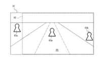
図3は、画像処理装置30が撮像装置20から取得した第1映像における検出領域61の第1例を示す。図3に示す例では、検出領域61は、上下方向に比べて左右方向に長い。表示領域62は、検出領域61の左右方向における中央に位置する。制御部33は、第1映像上の表示領域62の内側に映っている歩行者63および車両64それぞれを、検出対象として検出してよい。
(First example)
FIG. 3 shows a first example of the detection area 61 in the first video image acquired by the image processing apparatus 30 from the imaging device 20. In the example shown in FIG. 3, the detection area 61 is longer in the left-right direction than in the up-down direction. The display area 62 is located at the center of the detection area 61 in the left-right direction. The control unit 33 may detect each of the pedestrian 63 and the vehicle 64 reflected inside the display area 62 on the first image as a detection target.

制御部33は、第1映像上の表示領域62の内側で検出された検出対象と、移動体50と、の相対的位置関係に基づいて、1つ以上の条件が満たされているか否かを判定する。1つ以上の条件は、例えば検出対象が移動体50の第1予測進路65内に位置するとの第1条件を含んでよい。1つ以上の条件は、例えば移動体50の第1予測進路65の少なくとも一部と、検出対象の第2予測進路の少なくとも一部と、が重なるとの第2条件を含んでよい。当該1つ以上の条件が満たされると判定された場合、制御部33は、検出対象に対応する所定のマーカを、第2映像に重畳して表示装置40に表示させてよい。所定のマーカは、第1マーカ、第2マーカ、および第3マーカを含んでよい。 The control unit 33 determines whether or not one or more conditions are satisfied, based on the relative positional relationship between the detection target detected inside the display area 62 on the first image and the moving body 50. judge. The one or more conditions may include, for example, a first condition that the detection target is located in the first predicted path 65 of the moving body 50. The one or more conditions may include, for example, a second condition that at least a part of the first predicted path 65 of the moving object 50 and at least a part of the second predicted path of the detection target overlap. When it is determined that the one or more conditions are satisfied, the control unit 33 may superimpose a predetermined marker corresponding to the detection target on the second video and display the display device 40. The predetermined marker may include a first marker, a second marker, and a third marker.

第1例において、制御部33は、歩行者63について当該1つ以上の条件が満たされていると判定し得る。かかる場合、制御部33は、歩行者63に対応するマーカを表示させてよい。制御部33は、車両64について当該1つ以上の条件が満たされていないと判定し得る。かかる場合、制御部33は、車両64に対応するマーカを表示しない。 In the first example, the control unit 33 can determine that the one or more conditions for the pedestrian 63 are satisfied. In such a case, the control unit 33 may display the marker corresponding to the pedestrian 63. The control unit 33 may determine that the vehicle 64 does not satisfy the one or more conditions. In such a case, the control unit 33 does not display the marker corresponding to the vehicle 64.

図4は、図3に示す第1映像の表示領域62に対応する第2映像の例を示す。制御部33は、第1映像の表示領域62のアスペクト比と、表示装置40の画面のアスペクト比とが異なる場合、第1映像の表示領域62を切り出した後、表示装置40の画面のアスペクト比に合わせて変形した第2映像を、表示装置40へ出力してよい。図4に示すように、第2映像上に、歩行者63および車両64が映っている。 FIG. 4 shows an example of the second video corresponding to the display area 62 of the first video shown in FIG. When the aspect ratio of the display area 62 of the first image is different from the aspect ratio of the screen of the display device 40, the control unit 33 cuts out the display area 62 of the first image and then the aspect ratio of the screen of the display device 40. The second video transformed according to the above may be output to the display device 40. As shown in FIG. 4, the pedestrian 63 and the vehicle 64 are shown on the second image.

制御部33は、例えば図3に示す移動体50の第1予測進路65の少なくとも一部を示すガイド線66を、第2映像に重畳させて表示装置40に表示させてよい。制御部33は、例えばステアリングホイールの舵角の変化に応じて、ガイド線66を動的に変化させてよい。 The control unit 33 may display the guide line 66 indicating at least a part of the first predicted path 65 of the moving body 50 shown in FIG. 3 on the display device 40 by superimposing it on the second image. The control unit 33 may dynamically change the guide line 66 according to, for example, a change in the steering angle of the steering wheel.

第1映像は、表示領域62に比べて範囲が広い。制御部33は、表示領域62の範囲を変更し得る。制御部33は、第2映像にアイコン画像67を重畳させて表示装置40に表示させてよい。例えば図4に示すアイコン画像67の輪郭67aは、表示領域62の範囲を変更した際の最大範囲を示す。アイコン画像67の白い長方形67bは、表示領域62を示す。図4に示すアイコン画像67は、表示領域62の最大範囲に対する表示領域62の相対的な位置および大きさを示す。 The first image has a wider range than the display area 62. The control unit 33 can change the range of the display area 62. The control unit 33 may superimpose the icon image 67 on the second video and display it on the display device 40. For example, the outline 67a of the icon image 67 shown in FIG. 4 indicates the maximum range when the range of the display area 62 is changed. A white rectangle 67b of the icon image 67 indicates the display area 62. The icon image 67 shown in FIG. 4 indicates the relative position and size of the display area 62 with respect to the maximum range of the display area 62.

図5は、例えば第2映像上の歩行者63に重畳されるマーカの例を示す。以下、当該マーカを、第3マーカ68ともいう。第3マーカ68の輪郭線69は、第2映像上で検出された歩行者63の輪郭線に略一致してよい。第3マーカ68の輪郭線69の内側の領域70は、例えば検出対象の種類である「人」に対応する色またはパターンで塗り潰されてよい。制御部33は、第1映像上で歩行者63が検出されると、第2映像上の歩行者63に第3マーカ68を重畳して表示装置40に表示させてよい。かかる構成によれば、対象者60は、第2映像上の歩行者63を容易に視認可能となる。制御部33は、第3マーカ68を表示させてから所定時間が経過すると、当該第3マーカ68を非表示にしてよい。 FIG. 5 shows an example of markers that are superimposed on the pedestrian 63 on the second video, for example. Hereinafter, the marker is also referred to as a third marker 68. The contour line 69 of the third marker 68 may substantially match the contour line of the pedestrian 63 detected on the second image. The area 70 inside the contour line 69 of the third marker 68 may be filled with a color or a pattern corresponding to, for example, “person” that is the type of the detection target. When the pedestrian 63 is detected on the first image, the control unit 33 may superimpose the third marker 68 on the pedestrian 63 on the second image and display the third marker 68 on the display device 40. According to this structure, the target person 60 can easily visually recognize the pedestrian 63 on the second image. The control unit 33 may hide the third marker 68 when a predetermined time has elapsed after displaying the third marker 68.

図6は、例えば第2映像上の歩行者63の周辺に重畳される2種類のマーカの例を示す。以下、当該2種類のマーカそれぞれを、第1マーカ71および第2マーカ72ともいう。制御部33は、例えば第3マーカ68を非表示にした後に、第1マーカ71および第2マーカ72を、第2映像に重畳して表示装置40に表示させてよい。 FIG. 6 shows an example of two types of markers that are superimposed around the pedestrian 63 on the second image, for example. Hereinafter, each of the two types of markers is also referred to as a first marker 71 and a second marker 72. The control unit 33 may cause the display device 40 to display the first marker 71 and the second marker 72 by superimposing the first marker 71 and the second marker 72 on the second image after hiding the third marker 68, for example.

制御部33は、第2映像上の歩行者63に追従して、第1マーカ71の位置を移動させてよい。対象者60は、第1マーカ71が歩行者63に追従するので、歩行者63を捕らえやすい。第1マーカ71は、歩行者63の周囲に歩行者63から離れて表示される。対象者60は、第1マーカ71が表示装置40に表示されているときに、歩行者63の振る舞いを把握しやすい。制御部33は、第2映像上の第1マーカ71の重畳位置に対して、第2マーカ72の重畳位置を相対的に変化させてよい。制御部33は、第1マーカ71の位置を基準にして、第2マーカを相対的に移動させてよい。 The control unit 33 may follow the pedestrian 63 on the second video and move the position of the first marker 71. The target person 60 can easily catch the pedestrian 63 because the first marker 71 follows the pedestrian 63. The first marker 71 is displayed around the pedestrian 63 and away from the pedestrian 63. The target person 60 can easily understand the behavior of the pedestrian 63 when the first marker 71 is displayed on the display device 40. The control unit 33 may relatively change the superimposed position of the second marker 72 with respect to the superimposed position of the first marker 71 on the second image. The control unit 33 may relatively move the second marker based on the position of the first marker 71.

例えば、制御部33は、移動体50と歩行者63との間の距離が減少しているときに、当該距離の減少に対して移動体50の寄与が大きいと判定し得る。かかる場合、制御部33は、第2マーカ72を第1マーカ71に向かって移動させてよい。まず、制御部33は、第1マーカ71から離れた位置に第2マーカ72を表示させる。次に、制御部33は、第1マーカ71との距離が所定距離になるまで、第2マーカ72を第1マーカ71に向かって移動させる。次に、制御部33は、第2マーカ72を消す。次に、制御部33は、再び第1マーカ71から離れた位置に第2マーカ72を表示させ、上述の処理を繰り返す。この例において、第2マーカ72は、第1マーカ71という対象物に向かって移動しているため、対象者60は、第2マーカ72が第1マーカ71に向かって近づいていると理解し得る。 For example, when the distance between the moving body 50 and the pedestrian 63 is decreasing, the control unit 33 can determine that the moving body 50 greatly contributes to the decrease in the distance. In such a case, the control unit 33 may move the second marker 72 toward the first marker 71. First, the control unit 33 displays the second marker 72 at a position away from the first marker 71. Next, the control unit 33 moves the second marker 72 toward the first marker 71 until the distance from the first marker 71 becomes a predetermined distance. Next, the control unit 33 erases the second marker 72. Next, the control unit 33 causes the second marker 72 to be displayed again at a position away from the first marker 71, and repeats the above processing. In this example, since the second marker 72 is moving toward the object called the first marker 71, the target person 60 can understand that the second marker 72 is approaching the first marker 71. ..

例えば、制御部33は、移動体50と歩行者63との間の距離が減少しているときに、当該距離の減少に対して歩行者63の寄与が大きいと判定し得る。かかる場合、制御部33は、第2マーカ72を第1マーカ71から離れるように移動させてよい。まず、制御部33は、第1マーカ71に近い位置に第2マーカ72を表示させる。次に、制御部33は、第1マーカ71との距離が所定距離になるまで、第2マーカ72を第1マーカ71から離れるように移動させる。次に、制御部33は、第2マーカ72を消す。次に、制御部33は、再び第1マーカ71に近い位置に第2マーカ72を表示させ、上述の処理を繰り返す。この例において、第2マーカ72は、第1マーカ71という対象物から移動しているため、対象者60は、第2マーカ72が第1マーカ71に向かって離れていると理解し得る。 For example, when the distance between the moving body 50 and the pedestrian 63 is decreasing, the control unit 33 can determine that the pedestrian 63 greatly contributes to the decrease in the distance. In such a case, the control unit 33 may move the second marker 72 away from the first marker 71. First, the control unit 33 displays the second marker 72 at a position near the first marker 71. Next, the control unit 33 moves the second marker 72 away from the first marker 71 until the distance from the first marker 71 reaches a predetermined distance. Next, the control unit 33 erases the second marker 72. Next, the control unit 33 causes the second marker 72 to be displayed again at a position close to the first marker 71 and repeats the above processing. In this example, since the second marker 72 has moved from the object called the first marker 71, the target person 60 can understand that the second marker 72 is away from the first marker 71.

制御部33は、移動体50と歩行者63との間の距離の減少に対する移動体50および歩行者63の寄与の多寡に応じて、第1マーカ71に対する第2マーカ72の移動方向を変更する。対象者60は、第2マーカ72の移動方向に応じて、例えば移動体50が歩行者63に近付いているのか、または歩行者63が移動体50に近付いているのかを識別可能となる。 The control unit 33 changes the moving direction of the second marker 72 with respect to the first marker 71 according to the amount of contribution of the moving body 50 and the pedestrian 63 to the decrease in the distance between the moving body 50 and the pedestrian 63. .. The target person 60 can identify, for example, whether the moving body 50 is approaching the pedestrian 63 or the pedestrian 63 is approaching the moving body 50, depending on the moving direction of the second marker 72.

制御部33は、例えば図7に示すように、第2映像上の第1マーカ71を中心として第2マーカ72の拡大または縮小を繰り返してよい。制御部33は、例えば図8に示すように、歩行者63の輪郭線69と同様の形状を有する第1マーカ71および第2マーカ72を第2映像に重畳してよい。制御部33は、当該第1マーカ71を中心として第2マーカ72の拡大または縮小を繰り返してよい。制御部33は、移動体50と歩行者63との間の距離の減少に対する移動体50および歩行者63の寄与の多寡に応じて、第2マーカ72の拡大または縮小を切り替える。 For example, as shown in FIG. 7, the control unit 33 may repeat the enlargement or reduction of the second marker 72 with the first marker 71 on the second image as the center. For example, as shown in FIG. 8, the control unit 33 may superimpose the first marker 71 and the second marker 72 having the same shape as the contour line 69 of the pedestrian 63 on the second image. The control unit 33 may repeat the enlargement or reduction of the second marker 72 around the first marker 71. The control unit 33 switches the enlargement or reduction of the second marker 72 according to the amount of contribution of the moving body 50 and the pedestrian 63 to the decrease in the distance between the moving body 50 and the pedestrian 63.

制御部33は、第1マーカ71および第2マーカ72を表示している検出対象と移動体50との間の距離が所定の閾値未満となった場合、新たなマーカを第2映像に重畳してよい。以下、当該新たなマーカを第4マーカともいう。第4マーカは、任意の画像を含んでよい。例えば、第4マーカは、感嘆符「!」を示す画像を含んでよい。かかる構成によれば、例えば第1マーカ71および第2マーカ72を表示している歩行者63と移動体50とが一定程度以上近付くと、第4マーカが第2映像に重畳して表示される。対象者60は、第4マーカによって、例えば歩行者63が移動体50の近傍に位置することを識別可能となる。他の実施形態において、制御部33は、第1マーカ71および第2マーカ72を表示している検出対象と移動体50との間の距離が所定の閾値未満となった場合、当該第1マーカ71および第2マーカ72の表示態様を変化させてよい。制御部33は、例えば、第1マーカ71および第2マーカ72の色を変化させてよい。かかる構成によっても、対象者60は、マーカの色の変化によって、例えば歩行者63が移動体50の近傍に位置することを識別可能となる。 When the distance between the detection target displaying the first marker 71 and the second marker 72 and the moving body 50 is less than a predetermined threshold value, the control unit 33 superimposes a new marker on the second image. You can Hereinafter, the new marker is also referred to as a fourth marker. The fourth marker may include an arbitrary image. For example, the fourth marker may include an image showing an exclamation mark "!". According to this configuration, when the pedestrian 63 displaying the first marker 71 and the second marker 72 and the moving body 50 approach each other by a certain amount or more, for example, the fourth marker is displayed by being superimposed on the second image. .. The fourth marker enables the target person 60 to identify that the pedestrian 63 is located near the moving body 50, for example. In another embodiment, when the distance between the detection target displaying the first marker 71 and the second marker 72 and the moving body 50 is less than a predetermined threshold, the control unit 33 controls the first marker. The display modes of 71 and the second marker 72 may be changed. The control unit 33 may change the colors of the first marker 71 and the second marker 72, for example. With this configuration as well, the target person 60 can identify that the pedestrian 63 is located in the vicinity of the moving body 50, for example, by the change in the color of the marker.

制御部33は、奥行き方向の前後に並んだ2つの検出対象を検知し得る。制御部33は、前後に位置する2つの検出対象のそれぞれに、第1マーカ71および第2マーカ72を表示させてよい。制御部33は、2つの検出対象に対して、異なる第1マーカ71および第2マーカ72を付し得る。例えば、制御部33は、奥側に位置する第1の検出対象に対して、手前側に位置する第2の検出対象に付す第1マーカ71および第2マーカ72より目立たない第1マーカ71および第2マーカ72を付し得る。例えば、制御部33は、手前側に位置する第2の検出対象に付す第1マーカ71および第2マーカ72より、奥側に位置する第1の検出対象に付す第1マーカ71および第2マーカ72の、色を暗く、透過率を高く、線を細くする等の変更をし得る。 The control unit 33 can detect two detection targets arranged side by side in the depth direction. The control unit 33 may display the first marker 71 and the second marker 72 on each of the two detection targets located in the front and rear. The control unit 33 may attach different first markers 71 and second markers 72 to the two detection targets. For example, the control unit 33, with respect to the first detection target located on the back side, the first marker 71 and the second marker 72 attached to the second detection target located on the front side, and the first marker 71 and the second marker 72 which are less conspicuous. A second marker 72 may be attached. For example, the control unit 33 includes the first marker 71 and the second marker 72 attached to the second detection target located on the front side, and the first marker 71 and the second marker 71 attached to the first detection target located on the back side. Modifications of 72 such as darker color, higher transmission, thinner lines, etc. may be made.

(第2例)
図9は、画像処理装置30が撮像装置20から取得した第1映像における検出領域61の第2例を示す。図9に示す例では、検出領域61は、上下方向に比べて左右方向に長い。表示領域62は、検出領域61の左右方向における中央に位置する。制御部33は、第1映像上の表示領域62の内側に映っている歩行者63aと、表示領域62の外側であって検出領域61の内側に映っている歩行者63bおよび63cとを、それぞれ検出対象として検出してよい。歩行者63aに関する制御部33の処理は、例えば図3に示す歩行者63に関する処理と同様である。
(Second example)
FIG. 9 shows a second example of the detection area 61 in the first video image acquired by the image processing device 30 from the imaging device 20. In the example shown in FIG. 9, the detection area 61 is longer in the left-right direction than in the up-down direction. The display area 62 is located at the center of the detection area 61 in the left-right direction. The control unit 33 respectively detects a pedestrian 63a appearing inside the display area 62 on the first image and pedestrians 63b and 63c appearing outside the display area 62 and inside the detection area 61, respectively. It may be detected as a detection target. The process of the control unit 33 for the pedestrian 63a is similar to the process for the pedestrian 63 shown in FIG. 3, for example.

制御部33は、検出対象が検出された第1映像上の検出位置が、表示領域62の外側且つ検出領域61の内側である場合、検出対象に対応するマーカを第2映像に重畳して表示装置40に表示させてよい。以下、当該マーカを第5マーカともいう。制御部33は、移動体50と当該検出対象とが接触する可能性があると判定された場合に、第5マーカを表示させてよい。制御部33は、当該検出対象が検出された第1映像上の検出位置が、表示領域62よりも右側にある場合、第5マーカを、第2映像上の右端に重畳して表示装置40に表示させてよい。制御部33は、当該検出対象が検出された第1映像上の検出位置が、表示領域62よりも左側にある場合、第5マーカを、第2映像上の左端に重畳して表示装置40に表示させてよい。 When the detection position on the first video in which the detection target is detected is outside the display area 62 and inside the detection area 61, the control unit 33 superimposes and displays the marker corresponding to the detection target on the second video. It may be displayed on the device 40. Hereinafter, the marker is also referred to as a fifth marker. The control unit 33 may display the fifth marker when it is determined that the moving body 50 and the detection target may come into contact with each other. When the detection position on the first video where the detection target is detected is on the right side of the display area 62, the control unit 33 causes the display device 40 to superimpose the fifth marker on the right end on the second video. You may display it. When the detection position on the first video where the detection target is detected is on the left side of the display area 62, the control unit 33 causes the display device 40 to superimpose the fifth marker on the left end on the second video. You may display it.

第2例において、歩行者63bが検出された検出位置は、表示領域62よりも右側にある。制御部33は、移動体50と歩行者63bとが接触する可能性があると判定し得る。かかる場合、制御部33は、歩行者63bに対応する第5マーカを、第2映像上の右端に重畳して表示装置40に表示させてよい。歩行者63bに対応する第5マーカの詳細については後述する。歩行者63cが検出された検出位置は、表示領域62よりも左側にある。制御部33は、移動体50と歩行者63cとが接触する可能性がないと判定し得る。かかる場合、制御部33は、歩行者63bに対応する第5マーカを表示させなくてよい。 In the second example, the detection position where the pedestrian 63b is detected is on the right side of the display area 62. The control unit 33 can determine that the moving body 50 and the pedestrian 63b may come into contact with each other. In such a case, the control unit 33 may cause the display device 40 to display the fifth marker corresponding to the pedestrian 63b by superimposing it on the right end of the second image. Details of the fifth marker corresponding to the pedestrian 63b will be described later. The detection position where the pedestrian 63c is detected is on the left side of the display area 62. The control unit 33 can determine that the moving body 50 and the pedestrian 63c are not likely to come into contact with each other. In such a case, the control unit 33 does not have to display the fifth marker corresponding to the pedestrian 63b.

図10は、図9に示す第1映像の表示領域62に対応する第2映像の例を示す。図10に示すように、第2映像上に歩行者63aが映っている。第2映像上に歩行者63bおよび63cは映っていない。 FIG. 10 shows an example of the second video corresponding to the display area 62 of the first video shown in FIG. As shown in FIG. 10, the pedestrian 63a is shown on the second image. Pedestrians 63b and 63c are not shown in the second image.

図10に示すように、制御部33は、例えば障害物画像74を第2映像に重畳して表示装置40に表示させてよい。障害物画像57は、移動体50に備えられた超音波ソナー等を用いた障害物検出装置の検出結果を示す。障害物画像74は、画像74aと、画像74bと、画像74cとを含み得る。画像74aは、移動体50を上方から俯瞰した画像である。画像74bは、移動体50の左後方に障害物が検出されたことを示す画像である。画像74cは、移動体50の右後方に障害物が検出されたことを示す画像である。障害物検出装置による障害物の検出結果と、制御部33による検出対象の検出結果とは、必ずしも一致しなくてよい。例えば図10に示す例では、障害物画像74は、移動体50の右後方および左後方に、それぞれ障害物が検出されたことを示す。一方、制御部33は、移動体50の左後方に存在する歩行者63cについては、移動体50と接触する可能性がないと判定し得る。かかる場合、制御部33は、歩行者63cに対応する第5マーカを表示させなくてよい。 As shown in FIG. 10, the control unit 33 may display the obstacle image 74 on the display device 40 by superimposing the obstacle image 74 on the second image, for example. The obstacle image 57 shows the detection result of the obstacle detection device using the ultrasonic sonar or the like provided in the moving body 50. The obstacle image 74 may include an image 74a, an image 74b, and an image 74c. The image 74a is an image of the moving body 50 viewed from above. The image 74b is an image showing that an obstacle is detected on the left rear side of the moving body 50. The image 74c is an image indicating that an obstacle is detected on the right rear side of the moving body 50. The detection result of the obstacle by the obstacle detection device and the detection result of the detection target by the control unit 33 do not necessarily match. For example, in the example shown in FIG. 10, the obstacle image 74 indicates that obstacles are detected on the right rear side and the left rear side of the moving body 50, respectively. On the other hand, the control unit 33 can determine that there is no possibility that the pedestrian 63c existing on the left rear side of the moving body 50 will come into contact with the moving body 50. In such a case, the control unit 33 does not have to display the fifth marker corresponding to the pedestrian 63c.

歩行者63bに対応する第5マーカ73の例を図10に示す。第5マーカ73は、アイコン画像73aと、帯画像73bと、を含んでよい。アイコン画像73aは、検出対象の種類である「人」に対応する画像であってよい。アイコン画像73aを視認した対象者60は、第2映像よりも右方に人が存在することを認識可能である。帯画像73bは、例えば第2映像上の上下方向に延びる帯状の画像である。帯画像73bは、例えば検出対象の種類である「人」に対応する色またはパターンで塗り潰されてよい。制御部33は、第2映像上の右端領域73c内において、帯画像73bを移動させてよい。制御部33は、帯画像73bの移動速度および幅を変化させてよい。 An example of the fifth marker 73 corresponding to the pedestrian 63b is shown in FIG. The fifth marker 73 may include an icon image 73a and a band image 73b. The icon image 73a may be an image corresponding to “person” that is the type of detection target. The target person 60 who visually recognizes the icon image 73a can recognize that a person exists on the right side of the second video image. The band image 73b is, for example, a band-shaped image extending in the vertical direction on the second video. The strip image 73b may be filled with a color or a pattern corresponding to, for example, "person" that is the type of the detection target. The control unit 33 may move the band image 73b within the right end region 73c on the second video. The control unit 33 may change the moving speed and width of the band image 73b.

第5マーカ73について詳細に説明する。制御部33は、移動体50と歩行者63bとの間の距離に応じて、帯画像73bの幅を決定してよい。例えば、制御部33は、当該距離が近付くほど、帯画像73bの幅を太くしてよい。帯画像73bを視認した対象者60は、帯画像73bの幅に基づいて、移動体50と歩行者63bとの間の距離を認識可能である。 The fifth marker 73 will be described in detail. The control unit 33 may determine the width of the belt image 73b according to the distance between the moving body 50 and the pedestrian 63b. For example, the control unit 33 may increase the width of the band image 73b as the distance becomes shorter. The target person 60 who visually recognizes the belt image 73b can recognize the distance between the moving body 50 and the pedestrian 63b based on the width of the belt image 73b.

制御部33は、移動体50と歩行者63bとの間の距離の減少に対して、例えば移動体50の寄与が大きいと判定し得る。かかる場合、制御部33は、第2映像上の右端領域73c内において、帯画像73bを第1方向に繰り返し移動させる。第1方向は、例えば第2映像上の左右方向において外側から内側に向かう方向であってよい。制御部33は、移動体50と歩行者63bとの間の距離の減少に対して、例えば歩行者63bの寄与が大きいと判定し得る。かかる場合、制御部33は、第2映像上の右端領域73c内において、帯画像73bを第2方向に繰り返し移動させる。第2方向は、例えば第2映像上の左右方向において内側から外側に向かう方向であってよい。帯画像73bを視認した対象者60は、帯画像73bの移動方向に基づいて、移動体50が歩行者63bに近付いているのか、または歩行者63bが移動体50に近付いているのかを認識可能である。 The control unit 33 can determine that, for example, the contribution of the moving body 50 is large with respect to the decrease in the distance between the moving body 50 and the pedestrian 63b. In such a case, the control unit 33 repeatedly moves the strip image 73b in the first direction within the right end area 73c on the second video. The first direction may be, for example, a direction from the outer side to the inner side in the left-right direction on the second image. The control unit 33 can determine that, for example, the contribution of the pedestrian 63b is large with respect to the decrease in the distance between the moving body 50 and the pedestrian 63b. In such a case, the control unit 33 repeatedly moves the strip image 73b in the second direction within the right end area 73c on the second video. The second direction may be, for example, a direction from the inner side to the outer side in the left-right direction on the second image. The target person 60 who visually recognizes the belt image 73b can recognize whether the moving body 50 is approaching the pedestrian 63b or the pedestrian 63b is approaching the moving body 50 based on the moving direction of the belt image 73b. Is.

制御部33は、移動体50と歩行者63bとの間の距離の減少速度に応じて、帯画像73bの移動速度を決定してよい。例えば、当該距離の減少速度が速いほど、帯画像73bの移動速度を速くしてよい。帯画像73bを視認した対象者60は、帯画像73bの移動速度に基づいて、移動体50と歩行者63bとの間の距離の減少速度を認識可能である。 The control unit 33 may determine the moving speed of the belt image 73b according to the decreasing speed of the distance between the moving body 50 and the pedestrian 63b. For example, the moving speed of the band image 73b may be increased as the decreasing speed of the distance is increased. The target person 60 who visually recognizes the belt image 73b can recognize the decreasing speed of the distance between the moving body 50 and the pedestrian 63b based on the moving speed of the belt image 73b.

制御部33は、第5マーカ73を表示させた状態において、例えば所定のユーザ操作に応じたユーザ入力を検出すると、第1映像上の歩行者63bの検出位置が表示領域62の内側に含まれるように表示領域62を変化させてよい。例えば図11に示すように、制御部33は、第1映像上の表示領域62を左右方向に長くし、表示領域62を検出領域61内の右側に寄せてよい。かかる構成によって、例えば図12に示すように、第2映像上に歩行者63bが映る。 When the controller 33 detects a user input corresponding to a predetermined user operation in the state where the fifth marker 73 is displayed, the detection position of the pedestrian 63b on the first image is included inside the display area 62. The display area 62 may be changed as follows. For example, as shown in FIG. 11, the control unit 33 may lengthen the display area 62 on the first image in the left-right direction and shift the display area 62 to the right side in the detection area 61. With this configuration, for example, as shown in FIG. 12, the pedestrian 63b appears in the second image.

上述した所定のユーザ操作は、任意のユーザ操作を含んでよい。例えば、上述した所定のユーザ操作は、移動体50のステアリングの舵角を変化させる第1ユーザ操作を含んでよい。第5マーカ73は、第2ユーザ操作を受け付けるGUI(Graphic User Interface)として機能してよい。以下、GUIをインタフェース画像ともいう。かかる場合、上述した所定のユーザ操作は、第2ユーザ操作を含んでよい。 The predetermined user operation described above may include an arbitrary user operation. For example, the predetermined user operation described above may include a first user operation that changes the steering angle of the steering wheel of the moving body 50. The fifth marker 73 may function as a GUI (Graphic User Interface) that receives a second user operation. Hereinafter, the GUI is also referred to as an interface image. In such a case, the predetermined user operation described above may include the second user operation.

制御部33は、第1映像上の歩行者63bの検出位置が表示領域62の内側に含まれるように、表示領域62を自動的に変化させてよい。この場合、制御部33は、第1映像の検出領域61において歩行者63bが検出されなくなるまで、表示領域62の自動変更を維持し得る。 The control unit 33 may automatically change the display area 62 so that the detected position of the pedestrian 63b on the first image is included inside the display area 62. In this case, the control unit 33 can maintain the automatic change of the display area 62 until the pedestrian 63b is no longer detected in the detection area 61 of the first image.

制御部33は、例えば図12に示すように、表示領域62の変化に応じてアイコン画像67を変化させてよい。 The control unit 33 may change the icon image 67 according to a change in the display area 62, as shown in FIG. 12, for example.

制御部33は、例えば表示装置40に対するピンチイン操作およびピンチアウト操作等に応じて、第1映像上の表示領域62を変化させてよい。例えば図13に示すように、制御部33は、表示領域62を検出領域61に略一致させてよい。かかる場合、例えば図14に示すように、検出領域61内の全ての検出対象が表示装置40に表示される。 The control unit 33 may change the display area 62 on the first image in accordance with, for example, a pinch-in operation and a pinch-out operation with respect to the display device 40. For example, as shown in FIG. 13, the control unit 33 may make the display area 62 substantially coincide with the detection area 61. In such a case, for example, as shown in FIG. 14, all the detection targets in the detection area 61 are displayed on the display device 40.

(第3例)
図15は、画像処理装置30が撮像装置20から取得した第1映像における検出領域61の第3例を示す。図15に示す例では、検出領域61は、上下方向に比べて左右方向に長い。表示領域62は、検出領域61の左右方向における中央に位置する。制御部33は、移動体50の第1予測進路65内に映っている車両64aと、第1予測進路65外に映っている車両64bおよび歩行者63dとを、それぞれ検出対象として検出してよい。
(Third example)
FIG. 15 shows a third example of the detection area 61 in the first video image acquired by the image processing device 30 from the imaging device 20. In the example shown in FIG. 15, the detection area 61 is longer in the left-right direction than in the up-down direction. The display area 62 is located at the center of the detection area 61 in the left-right direction. The control unit 33 may detect the vehicle 64a reflected in the first predicted path 65 of the moving body 50, the vehicle 64b reflected outside the first predicted path 65, and the pedestrian 63d as detection targets. ..

第3例では、例えば夜間またはトンネル内等、移動体50の外部領域が暗い場合について説明する。移動体50の外部領域が暗い場合、第1映像および第2映像の特性値が低下する場合がある。特性値は、映像の視認性に関する任意のパラメータを含んでよい。例えば、特性値は、例えば映像の輝度値およびコントラスト比のうち少なくとも一方を含んでよい。第2映像の特性値が低下すると、第2映像の視認性が低下し得る。 In the third example, a case where the external area of the moving body 50 is dark, such as at night or in a tunnel, will be described. When the external area of the moving body 50 is dark, the characteristic values of the first image and the second image may decrease. The characteristic value may include any parameter relating to the visibility of the image. For example, the characteristic value may include at least one of a luminance value and a contrast ratio of the image, for example. When the characteristic value of the second image decreases, the visibility of the second image may decrease.

制御部33は、第2映像上の検出対象に対応する領域に対して、特定画像処理を実行してよい。特定画像処理は、検出対象に対応するマーカを当該領域に重畳する第1処理を含んでよい。以下、当該マーカを第6マーカともいう。第6マーカは、例えば第2映像上の検出対象の輪郭形状に略一致する画像を含んでよい。かかる構成によれば、第2映像上の検出対象に第6マーカが重畳して表示される。このため、対象者60は、第2映像の特性値が低い場合であっても、第2映像上の検出対象を容易に認識可能である。特定画像処理は、第2映像上の検出対象に対応する当該領域の特性値を変化させる第2処理を含んでよい。例えば、制御部33は、第2映像上の当該領域の視認性を向上させるように、当該領域の特性値を変化させてよい。かかる構成によれば、第2映像上の検出対象の視認性が向上する。このため、対象者60は、第2映像の特性値が低い場合であっても、第2映像上の検出対象を容易に認識可能である。 The control unit 33 may perform the specific image processing on the area corresponding to the detection target on the second video. The specific image processing may include a first processing of superimposing a marker corresponding to the detection target on the area. Hereinafter, the marker is also referred to as a sixth marker. The sixth marker may include, for example, an image that substantially matches the contour shape of the detection target on the second video. With this configuration, the sixth marker is displayed so as to be superimposed on the detection target on the second video. Therefore, the target person 60 can easily recognize the detection target on the second video even when the characteristic value of the second video is low. The specific image processing may include second processing for changing the characteristic value of the area corresponding to the detection target on the second video. For example, the control unit 33 may change the characteristic value of the area so as to improve the visibility of the area on the second image. With this configuration, the visibility of the detection target on the second image is improved. Therefore, the target person 60 can easily recognize the detection target on the second video even when the characteristic value of the second video is low.

制御部33は、1つ以上の条件が満たされる場合に、上述の特定画像処理を実行してよい。1つ以上の条件は、検出対象が移動体50の第1予測進路65内に位置するとの条件を含んでよい。1つ以上の条件は、移動体50の第1予測進路65と、検出対象の第2予測進路とが重なるとの条件を含んでよい。1つ以上の条件は、移動体50と検出対象との間の距離が所定の閾値未満であるとの条件を含んでよい。1つ以上の条件は、第2映像の少なくとも一部の領域の特性値が、所定の閾値未満であるとの条件を含んでよい。 The control unit 33 may execute the specific image processing described above when one or more conditions are satisfied. The one or more conditions may include a condition that the detection target is located within the first predicted path 65 of the moving body 50. The one or more conditions may include a condition that the first predicted path 65 of the moving body 50 and the second predicted path of the detection target overlap. The one or more conditions may include a condition that the distance between the moving body 50 and the detection target is less than a predetermined threshold value. The one or more conditions may include a condition that the characteristic value of at least a part of the region of the second image is less than a predetermined threshold value.

第3例において、制御部33は、車両64a、64b、および歩行者63dそれぞれについて、上述した1つ以上の条件が満たされると判定し得る。かかる場合、制御部33は、例えば図16に示すように、車両64a、64b、および歩行者63dにそれぞれ対応する3つの第6マーカ75a、75b、および75cを、第2映像に重畳して表示装置40に表示させてよい。制御部33は、明るい場所において、検出対象に第6マーカを重ねて表示させてよい。 In the third example, the control unit 33 can determine that one or more conditions described above are satisfied for each of the vehicles 64a and 64b and the pedestrian 63d. In such a case, the control unit 33 superimposes and displays the three sixth markers 75a, 75b, and 75c corresponding to the vehicles 64a and 64b and the pedestrian 63d on the second video, as shown in FIG. 16, for example. It may be displayed on the device 40. The control unit 33 may display the sixth marker so as to overlap the detection target in a bright place.

制御部33は、ガイド線66の形状を変更してよい。制御部33は、ガイド線66と検出対象とが重なる領域におけるガイド線66の形状を変更してよい。図17は、ガイド線66の形状例の1つである。図17のガイド線66は、ガイド線66と第6マーカ75aが重なっている領域に、ガイド線が表示されていない。ガイド線66の形状例は、消去に限られず、他のデザイン変更を許容する。デザイン変更には、色の変更、透過率の変更、破線等への種別の変更、線の太さの変更、および点滅等が含まれる。制御部33は、第6マーカが表示されていないときに、ガイド線66の形状を変更してよい。制御部33は、検出対象に第1マーカ71および第2マーカ72を表示しているときに、ガイド線66の形状を変更してよい。 The controller 33 may change the shape of the guide wire 66. The control unit 33 may change the shape of the guide line 66 in the region where the guide line 66 and the detection target overlap. FIG. 17 shows one example of the shape of the guide wire 66. In the guide line 66 of FIG. 17, the guide line is not displayed in the area where the guide line 66 and the sixth marker 75a overlap. The shape example of the guide line 66 is not limited to erasing, and other design changes are allowed. The design change includes a color change, a transmittance change, a type change to a broken line, a line thickness change, blinking, and the like. The controller 33 may change the shape of the guide line 66 when the sixth marker is not displayed. The controller 33 may change the shape of the guide line 66 when the first marker 71 and the second marker 72 are displayed on the detection target.

以上述べたように、一実施形態に係る表示システム10によれば、第1映像上で検出された検出対象に応じた多様なマーカが、第2映像に重畳して表示装置40に表示される。マーカを視認する対象者60は、移動体50と検出対象との相対的位置関係を一見して認識可能である。このため、移動体50の外部領域の映像を表示する技術の利便性が向上する。 As described above, according to the display system 10 according to the embodiment, various markers corresponding to the detection target detected on the first video are displayed on the display device 40 while being superimposed on the second video. .. The target person 60 who visually recognizes the marker can recognize the relative positional relationship between the moving body 50 and the detection target at a glance. Therefore, the convenience of the technique for displaying the image of the external area of the moving body 50 is improved.

本発明を諸図面や実施形態に基づき説明してきたが、当業者であれば本開示に基づき種々の変形や修正を行うことが容易であることに注意されたい。したがって、これらの変形や修正は本発明の範囲に含まれることに留意されたい。例えば、各手段、各ステップ等に含まれる機能等は論理的に矛盾しないように再配置可能であり、複数の手段やステップ等を1つに組み合わせたり、あるいは分割したりすることが可能である。 Although the present invention has been described based on the drawings and the embodiments, it should be noted that those skilled in the art can easily make various variations and modifications based on the present disclosure. Therefore, it should be noted that these variations and modifications are included in the scope of the present invention. For example, the functions and the like included in each means and each step can be rearranged so as not to be logically contradictory, and a plurality of means and steps can be combined or divided. ..

例えば、上述した実施形態に係る表示システム10の各構成要素および機能は再配置可能であってよい。例えば、画像処理装置30の構成および機能の一部または全部を、撮像装置20および表示装置40の少なくとも一方に包含させてもよい。 For example, each component and function of the display system 10 according to the above-described embodiment may be rearrangeable. For example, part or all of the configuration and function of the image processing device 30 may be included in at least one of the image capturing device 20 and the display device 40.

上述の実施形態に係る表示システム10の構成要素の一部は、移動体50の外部に位置してよい。例えば、画像処理装置30等は、携帯電話または外部サーバ等の通信機器として実現され、表示システム10の他の構成要素と有線または無線によって接続されてもよい。 Some of the components of the display system 10 according to the above-described embodiment may be located outside the moving body 50. For example, the image processing device 30 or the like may be realized as a communication device such as a mobile phone or an external server, and may be connected to other components of the display system 10 by wire or wirelessly.

10 表示システム
20 撮像装置
21 撮像光学系
22 撮像素子
23 通信部
24 制御部
30 画像処理装置
31 通信部
32 記憶部
33 制御部
40 表示装置
50 移動体
51 ネットワーク
60 対象者
61 検出領域
62 表示領域
63、63a、63b、63c、63d 歩行者
64、64a、64b 車両
65 第1予測進路
66 ガイド線
67 アイコン画像
68 第3マーカ
69 輪郭線
70 領域
71 第1マーカ
72 第2マーカ
73 第5マーカ
73a アイコン画像
73b 帯画像
73c 右端領域
74 障害物画像
75a、75b、75c 第6マーカ
10 display system 20 image pickup device 21 image pickup optical system 22 image pickup element 23 communication unit 24 control unit 30 image processing device 31 communication unit 32 storage unit 33 control unit 40 display device 50 mobile unit 51 network 60 target person 61 detection region 62 display region 63 , 63a, 63b, 63c, 63d Pedestrian 64, 64a, 64b Vehicle 65 First predicted path 66 Guide line 67 Icon image 68 Third marker 69 Contour line 70 Region 71 First marker 72 Second marker 73 Fifth marker 73a Icon Image 73b Belt image 73c Right edge region 74 Obstacle images 75a, 75b, 75c Sixth marker

Claims (8)

移動体の外部領域を撮像した第1映像を取得する通信部と、
前記第1映像上の表示領域に対応する第2映像を表示装置に表示させる制御部と、
を備え、
前記制御部は、
前記第1映像上の検出領域において検出対象の少なくとも一部を検出し、
前記検出対象の前記少なくとも一部が検出された前記第1映像上の検出位置が、前記表示領域の外側且つ前記検出領域の内側にあり、かつ前記移動体と前記検出対象との間の距離が減少する場合、前記距離の減少に対して前記移動体と前記検出対象との何れの寄与が大きいか判定し、
前記移動体の寄与が大きいと判定した場合、前記検出対象に対応するマーカの少なくとも一部が前記第2映像上で第1方向に移動するように、前記マーカを前記第2映像に重畳して前記表示装置に表示させ、
前記検出対象の寄与が大きいと判定した場合、前記マーカの前記少なくとも一部が前記第2映像上で第2方向に移動するように、前記マーカを前記第2映像に重畳して前記表示装置に表示させる、画像処理装置。
A communication unit that acquires a first image of an external area of the moving body;
A control unit for causing a display device to display a second image corresponding to a display area on the first image;
Equipped with
The control unit is
Detecting at least a part of a detection target in the detection area on the first image,
The distance between the detection position on the at least partially detected the first image of the detection target, Ri inside near the outer and the detection region of the display region, and the movable body and the detection target If decreases, it is determined which contribution of the moving body and the detection target to the decrease of the distance is large,
When it is determined that the contribution of the moving body is large, the marker is superimposed on the second video so that at least a part of the marker corresponding to the detection target moves in the first direction on the second video. Display on the display device,
If it is determined that the contribution of the detection target is large, so that at least a portion of the marker is moved in the second direction on the second image, the display device by superimposing the marker before Symbol second image Image processing device to be displayed on.
請求項1に記載の画像処理装置であって、The image processing apparatus according to claim 1, wherein
前記第1方向は、前記第2映像上の左右方向において外側から内側に向かう方向であり、The first direction is a direction from the outer side to the inner side in the left-right direction on the second image,
前記第2方向は、前記第2映像上の左右方向において内側から外側に向かう方向である、画像処理装置。The image processing device, wherein the second direction is a direction from the inner side to the outer side in the left-right direction on the second image.
請求項1または2に記載の画像処理装置であって、
前記検出対象は、複数種類の物体を含み、
前記制御部は、前記第1映像上で検出された物体の種類に応じて、前記マーカの色および形状の少なくとも一方を決定する、画像処理装置。
The image processing apparatus according to claim 1 or 2 , wherein
The detection target includes a plurality of types of objects,
The image processing apparatus, wherein the control unit determines at least one of the color and the shape of the marker according to the type of the object detected on the first video.
請求項1乃至3の何れか一項に記載の画像処理装置であって、
前記制御部は、前記移動体と前記検出対象との間の距離の減少速度に応じて、前記マーカの前記少なくとも一部の移動速度を決定する、画像処理装置。
The image processing apparatus according to any one of claims 1 to 3 ,
The image processing apparatus, wherein the control unit determines a moving speed of the at least a part of the marker according to a decreasing speed of a distance between the moving body and the detection target.
請求項1乃至4の何れか一項に記載の画像処理装置であって、
前記制御部は、前記移動体と前記検出対象との間の距離に応じて、前記マーカの少なくとも一部の幅を変化させる、画像処理装置。
The image processing apparatus according to any one of claims 1 to 4,
The said control part is an image processing apparatus which changes the width|variety of at least one part of the said marker according to the distance between the said moving body and the said detection object.
請求項1乃至5の何れか一項に記載の画像処理装置であって、
前記制御部は、
前記検出対象が検出された前記第1映像上の検出位置が前記表示領域よりも右側にある場合、前記マーカを、前記第2映像の右端に重畳して前記表示装置に表示させ、
前記検出位置が前記表示領域よりも左側にある場合、前記マーカを、前記第2映像の左端に重畳して前記表示装置に表示させる、画像処理装置。
The image processing apparatus according to any one of claims 1 to 5, wherein
The control unit is
When the detection position on the first video in which the detection target is detected is on the right side of the display area, the marker is displayed on the display device by being superimposed on the right end of the second video,
An image processing apparatus, wherein when the detected position is on the left side of the display area, the marker is displayed on the display device by being superimposed on the left end of the second image.
移動体の外部領域を撮像した第1映像を生成する撮像素子と、
前記第1映像上の表示領域に対応する第2映像を表示装置に表示させる制御部と、
を備え、
前記制御部は、
前記第1映像上の検出領域において検出対象の少なくとも一部を検出し、
前記検出対象の前記少なくとも一部が検出された前記第1映像上の検出位置が、前記表示領域の外側且つ前記検出領域の内側にあり、かつ前記移動体と前記検出対象との間の距離が減少する場合、前記距離の減少に対して前記移動体と前記検出対象との何れの寄与が大きいか判定し、前記移動体の寄与が大きいと判定した場合、前記検出対象に対応するマーカの少なくとも一部が前記第2映像上で第1方向に移動するように、前記マーカを前記第2映像に重畳して前記表示装置に表示させ、前記検出対象の寄与が大きいと判定した場合、前記マーカの前記少なくとも一部が前記第2映像上で第2方向に移動するように前記マーカを前記第2映像に重畳して前記表示装置に表示させる、撮像装置。
An image sensor for generating a first image of the external area of the moving body;
A control unit for causing a display device to display a second image corresponding to a display area on the first image;
Equipped with
The control unit is
Detecting at least a part of a detection target in the detection area on the first image,
The distance between the detection position on the at least partially detected the first image of the detection target, Ri inside near the outer and the detection region of the display region, and the movable body and the detection target If it decreases, it is determined which contribution of the moving body and the detection target to the decrease of the distance is large, and when it is determined that the contribution of the moving body is large, the marker corresponding to the detection target When it is determined that the marker is superimposed on the second image and displayed on the display device so that at least a part of the marker moves in the first direction on the second image, and the contribution of the detection target is large, as at least a part of the marker is moved in the second direction on the second image, to be displayed on the display device by superimposing the marker before Symbol second image, the imaging apparatus.
表示装置と、
移動体の外部領域を撮像した第1映像を生成する撮像装置と、
前記第1映像上の表示領域に対応する第2映像を前記表示装置に表示させる画像処理装置と、を備え、
前記画像処理装置は、
前記第1映像上の検出領域において検出対象の少なくとも一部を検出し、
前記検出対象の前記少なくとも一部が検出された前記第1映像上の検出位置が、前記表示領域の外側且つ前記検出領域の内側にあり、かつ前記移動体と前記検出対象との間の距離が減少する場合、前記距離の減少に対して前記移動体と前記検出対象との何れの寄与が大きいか判定し、前記移動体の寄与が大きいと判定した場合、前記検出対象に対応するマーカの少なくとも一部が前記第2映像上で第1方向に移動するように、前記マーカを前記第2映像に重畳して前記表示装置に表示させ、前記検出対象の寄与が大きいと判定した場合、前記マーカの前記少なくとも一部が前記第2映像上で第2方向に移動するように前記マーカを前記第2映像に重畳して前記表示装置に表示させる、表示システム。
A display device,
An imaging device that generates a first video imaged of an external area of the moving body;
An image processing device which causes the display device to display a second video image corresponding to a display area on the first video image,
The image processing device,
Detecting at least a part of the detection target in the detection area on the first image,
The distance between the detection position on the at least partially detected the first image of the detection target, Ri inside near the outer and the detection region of the display region, and the movable body and the detection target If it decreases, it is determined which contribution of the moving body and the detection target to the decrease of the distance is large, and when it is determined that the contribution of the moving body is large, the marker corresponding to the detection target When it is determined that the marker is superimposed on the second image and displayed on the display device so that at least a part of the marker moves in the first direction on the second image, and the contribution of the detection target is large, as at least a part of the marker is moved in the second direction on the second image, to be displayed on the display device by superimposing the marker before Symbol second video display system.
JP2016226334A 2016-11-21 2016-11-21 Image processing device, imaging device, and display system Active JP6720063B2 (en)

Priority Applications (4)

Application Number Priority Date Filing Date Title
JP2016226334A JP6720063B2 (en) 2016-11-21 2016-11-21 Image processing device, imaging device, and display system
EP17871828.4A EP3544293B1 (en) 2016-11-21 2017-11-21 Image processing device, imaging device, and display system
US16/462,488 US11030468B2 (en) 2016-11-21 2017-11-21 Image processing apparatus
PCT/JP2017/041900 WO2018092919A1 (en) 2016-11-21 2017-11-21 Image processing device, imaging device, and display system

Applications Claiming Priority (1)

Application Number Priority Date Filing Date Title
JP2016226334A JP6720063B2 (en) 2016-11-21 2016-11-21 Image processing device, imaging device, and display system

Publications (2)

Publication Number Publication Date
JP2018085582A JP2018085582A (en) 2018-05-31
JP6720063B2 true JP6720063B2 (en) 2020-07-08

Family

ID=62237302

Family Applications (1)

Application Number Title Priority Date Filing Date
JP2016226334A Active JP6720063B2 (en) 2016-11-21 2016-11-21 Image processing device, imaging device, and display system

Country Status (1)

Country Link
JP (1) JP6720063B2 (en)

Family Cites Families (5)

* Cited by examiner, † Cited by third party
Publication number Priority date Publication date Assignee Title
JP2009040107A (en) * 2007-08-06 2009-02-26 Denso Corp Image display control device and image display control system
CN102782740B (en) * 2010-03-01 2015-04-15 本田技研工业株式会社 Surrounding area monitoring device for vehicle
JP5861449B2 (en) * 2011-12-26 2016-02-16 アイシン精機株式会社 Obstacle alarm device
JP2015008453A (en) * 2013-05-29 2015-01-15 京セラ株式会社 Camera device and warning method
JP6232759B2 (en) * 2013-06-07 2017-11-22 ソニー株式会社 Information processing apparatus, approaching object notification method, and program

Also Published As

Publication number Publication date
JP2018085582A (en) 2018-05-31

Similar Documents

Publication Publication Date Title
US11961162B2 (en) Imaging apparatus, image processing apparatus, display system, and vehicle
WO2014129026A1 (en) Driving assistance device and image processing program
US10930070B2 (en) Periphery monitoring device
JP6626817B2 (en) Camera monitor system, image processing device, vehicle, and image processing method
JP6930971B2 (en) Display devices, display systems, and mobiles
JP2018085584A (en) Image processing apparatus, imaging apparatus, and display system
JP6781035B2 (en) Imaging equipment, image processing equipment, display systems, and vehicles
JP6762863B2 (en) Imaging equipment, image processing equipment, display systems, and vehicles
WO2018092919A1 (en) Image processing device, imaging device, and display system
JP6720063B2 (en) Image processing device, imaging device, and display system
JP6712942B2 (en) Image processing device, imaging device, and display system
KR102023863B1 (en) Display method around moving object and display device around moving object
JP6759072B2 (en) Image processing equipment, imaging equipment, and display system
JP7296490B2 (en) Display control device and vehicle
JP6974564B2 (en) Display control device
JP7007438B2 (en) Imaging equipment, image processing equipment, display equipment, display systems, and vehicles
JP2021007255A (en) Imaging device, image processing apparatus, display system, and vehicle

Legal Events

Date Code Title Description
A621 Written request for application examination

Free format text: JAPANESE INTERMEDIATE CODE: A621

Effective date: 20190222

A131 Notification of reasons for refusal

Free format text: JAPANESE INTERMEDIATE CODE: A131

Effective date: 20200317

A521 Written amendment

Free format text: JAPANESE INTERMEDIATE CODE: A523

Effective date: 20200512

TRDD Decision of grant or rejection written
A01 Written decision to grant a patent or to grant a registration (utility model)

Free format text: JAPANESE INTERMEDIATE CODE: A01

Effective date: 20200602

A61 First payment of annual fees (during grant procedure)

Free format text: JAPANESE INTERMEDIATE CODE: A61

Effective date: 20200617

R150 Certificate of patent or registration of utility model

Ref document number: 6720063

Country of ref document: JP

Free format text: JAPANESE INTERMEDIATE CODE: R150