JP6719676B2 - Scroll compressor - Google Patents

Scroll compressor Download PDF

Info

Publication number
JP6719676B2
JP6719676B2 JP2019533856A JP2019533856A JP6719676B2 JP 6719676 B2 JP6719676 B2 JP 6719676B2 JP 2019533856 A JP2019533856 A JP 2019533856A JP 2019533856 A JP2019533856 A JP 2019533856A JP 6719676 B2 JP6719676 B2 JP 6719676B2
Authority
JP
Japan
Prior art keywords
slider
outer peripheral
weight portion
peripheral surface
cylindrical portion
Prior art date
Legal status (The legal status is an assumption and is not a legal conclusion. Google has not performed a legal analysis and makes no representation as to the accuracy of the status listed.)
Active
Application number
JP2019533856A
Other languages
Japanese (ja)
Other versions
JPWO2019026272A1 (en
Inventor
功一 福原
功一 福原
友寿 松井
友寿 松井
祐司 ▲高▼村
祐司 ▲高▼村
Current Assignee (The listed assignees may be inaccurate. Google has not performed a legal analysis and makes no representation or warranty as to the accuracy of the list.)
Mitsubishi Electric Corp
Original Assignee
Mitsubishi Electric Corp
Priority date (The priority date is an assumption and is not a legal conclusion. Google has not performed a legal analysis and makes no representation as to the accuracy of the date listed.)
Filing date
Publication date
Application filed by Mitsubishi Electric Corp filed Critical Mitsubishi Electric Corp
Publication of JPWO2019026272A1 publication Critical patent/JPWO2019026272A1/en
Application granted granted Critical
Publication of JP6719676B2 publication Critical patent/JP6719676B2/en
Active legal-status Critical Current
Anticipated expiration legal-status Critical

Links

Images

Classifications

    • FMECHANICAL ENGINEERING; LIGHTING; HEATING; WEAPONS; BLASTING
    • F04POSITIVE - DISPLACEMENT MACHINES FOR LIQUIDS; PUMPS FOR LIQUIDS OR ELASTIC FLUIDS
    • F04CROTARY-PISTON, OR OSCILLATING-PISTON, POSITIVE-DISPLACEMENT MACHINES FOR LIQUIDS; ROTARY-PISTON, OR OSCILLATING-PISTON, POSITIVE-DISPLACEMENT PUMPS
    • F04C18/00Rotary-piston pumps specially adapted for elastic fluids
    • F04C18/02Rotary-piston pumps specially adapted for elastic fluids of arcuate-engagement type, i.e. with circular translatory movement of co-operating members, each member having the same number of teeth or tooth-equivalents
    • F04C18/0207Rotary-piston pumps specially adapted for elastic fluids of arcuate-engagement type, i.e. with circular translatory movement of co-operating members, each member having the same number of teeth or tooth-equivalents both members having co-operating elements in spiral form
    • F04C18/0215Rotary-piston pumps specially adapted for elastic fluids of arcuate-engagement type, i.e. with circular translatory movement of co-operating members, each member having the same number of teeth or tooth-equivalents both members having co-operating elements in spiral form where only one member is moving
    • FMECHANICAL ENGINEERING; LIGHTING; HEATING; WEAPONS; BLASTING
    • F04POSITIVE - DISPLACEMENT MACHINES FOR LIQUIDS; PUMPS FOR LIQUIDS OR ELASTIC FLUIDS
    • F04CROTARY-PISTON, OR OSCILLATING-PISTON, POSITIVE-DISPLACEMENT MACHINES FOR LIQUIDS; ROTARY-PISTON, OR OSCILLATING-PISTON, POSITIVE-DISPLACEMENT PUMPS
    • F04C29/00Component parts, details or accessories of pumps or pumping installations, not provided for in groups F04C18/00 - F04C28/00
    • F04C29/0021Systems for the equilibration of forces acting on the pump
    • FMECHANICAL ENGINEERING; LIGHTING; HEATING; WEAPONS; BLASTING
    • F04POSITIVE - DISPLACEMENT MACHINES FOR LIQUIDS; PUMPS FOR LIQUIDS OR ELASTIC FLUIDS
    • F04CROTARY-PISTON, OR OSCILLATING-PISTON, POSITIVE-DISPLACEMENT MACHINES FOR LIQUIDS; ROTARY-PISTON, OR OSCILLATING-PISTON, POSITIVE-DISPLACEMENT PUMPS
    • F04C2210/00Fluid
    • F04C2210/26Refrigerants with particular properties, e.g. HFC-134a
    • F04C2210/268R32
    • FMECHANICAL ENGINEERING; LIGHTING; HEATING; WEAPONS; BLASTING
    • F04POSITIVE - DISPLACEMENT MACHINES FOR LIQUIDS; PUMPS FOR LIQUIDS OR ELASTIC FLUIDS
    • F04CROTARY-PISTON, OR OSCILLATING-PISTON, POSITIVE-DISPLACEMENT MACHINES FOR LIQUIDS; ROTARY-PISTON, OR OSCILLATING-PISTON, POSITIVE-DISPLACEMENT PUMPS
    • F04C2240/00Components
    • F04C2240/60Shafts
    • FMECHANICAL ENGINEERING; LIGHTING; HEATING; WEAPONS; BLASTING
    • F04POSITIVE - DISPLACEMENT MACHINES FOR LIQUIDS; PUMPS FOR LIQUIDS OR ELASTIC FLUIDS
    • F04CROTARY-PISTON, OR OSCILLATING-PISTON, POSITIVE-DISPLACEMENT MACHINES FOR LIQUIDS; ROTARY-PISTON, OR OSCILLATING-PISTON, POSITIVE-DISPLACEMENT PUMPS
    • F04C2240/00Components
    • F04C2240/80Other components
    • F04C2240/807Balance weight, counterweight

Landscapes

  • Engineering & Computer Science (AREA)
  • Mechanical Engineering (AREA)
  • General Engineering & Computer Science (AREA)
  • Rotary Pumps (AREA)
  • Applications Or Details Of Rotary Compressors (AREA)

Description

本発明は、例えば冷凍機又は空気調和機に用いられるスクロール圧縮機に関するものである。 The present invention relates to a scroll compressor used in, for example, a refrigerator or an air conditioner.

特許文献1には、バランスウエイト付きスライダを有するスクロール圧縮機が記載されている。このスクロール圧縮機において、バランスウエイト付きスライダの重心の軸方向位置は、揺動軸受とスライダ部外周面との軸方向の回転摺動範囲の中央位置にほぼ一致している。これにより、バランスウエイト付きスライダに作用する遠心力の作用点と、その遠心力を半径方向に支持する支持点とが、ほぼ同一平面上に配置されることになるため、揺動軸受とスライダ部外周面との片当たりを防止できる。 Patent Document 1 describes a scroll compressor having a slider with a balance weight. In this scroll compressor, the axial position of the center of gravity of the slider with balance weight is substantially coincident with the central position of the axial sliding range between the rocking bearing and the outer peripheral surface of the slider portion. As a result, the action point of the centrifugal force acting on the slider with balance weight and the support point for radially supporting the centrifugal force are arranged on substantially the same plane. It is possible to prevent uneven contact with the outer peripheral surface.

特開平10−281083号公報Japanese Patent Laid-Open No. 10-281083

バランスウエイト付きのスライダの遠心力作用中心の軸方向位置を上記回転摺動範囲の中央位置に一致させ、かつ当該スライダの軸方向寸法又は径方向寸法の増加を抑えるためには、スライダの形状を複雑化する必要がある。したがって、スライダの加工工程が増加し、それに伴いスライダの加工コストが増加してしまうという課題があった。 In order to match the axial position of the centrifugal force acting center of the slider with balance weight with the central position of the above-mentioned rotary sliding range and to suppress the increase of the axial dimension or radial dimension of the slider, the slider shape should be changed. It needs to be complicated. Therefore, there has been a problem that the slider manufacturing process is increased, and accordingly the slider processing cost is increased.

本発明は、上述のような課題を解決するためになされたものであり、揺動軸受とスライダとの片当たりを防止しつつ、スライダの加工工程を削減できるスクロール圧縮機を提供することを目的とする。 The present invention has been made to solve the above-described problems, and an object of the present invention is to provide a scroll compressor capable of reducing the slider manufacturing process while preventing the swing bearing and the slider from being unbalanced. And

本発明に係るスクロール圧縮機は、固定スクロールと、前記固定スクロールに対して揺動する揺動スクロールと、前記揺動スクロールに回転駆動力を伝達する主軸と、前記主軸の一端に設けられ、前記主軸の中心軸に対して偏芯方向に偏芯した偏芯軸部と、前記偏芯軸部が摺動自在に挿入されるスライド溝が形成されたスライダと、前記揺動スクロールに設けられ、前記スライダを回転自在に支持する揺動軸受と、を備え、前記スライダは、前記揺動軸受に回転自在に支持される円筒部と、前記円筒部の外周側に設けられたバランスウエイト部と、を有しており、前記偏芯方向の逆方向を反偏芯方向としたとき、前記バランスウエイト部は、前記スライダの回転中心よりも前記偏芯方向側に設けられ、前記円筒部に接続されたカウンタウエイト部と、前記スライダの回転中心よりも前記反偏芯方向側に設けられ、前記円筒部に接続された第1メインウエイト部と、前記スライダの回転中心よりも前記反偏芯方向側に設けられ、前記第1メインウエイト部の外周部から前記揺動スクロール側に突出した第2メインウエイト部と、を有しており、前記カウンタウエイト部は、前記スライダの回転中心を中心とする部分円筒面状の第1外周面を有しており、前記第1メインウエイト部は、前記円筒部の中心軸を中心とする部分円筒面状の第2外周面を有しており、前記第2メインウエイト部は、前記第2外周面よりも外周側に位置し、前記スライダの回転中心を中心とする部分円筒面状の第3外周面と、前記円筒部の中心軸を中心とする部分円筒面状の内周面と、を有しているものである。 A scroll compressor according to the present invention is provided with a fixed scroll, an orbiting scroll that oscillates with respect to the fixed scroll, a main shaft that transmits a rotational driving force to the orbiting scroll, and one end of the main shaft, An eccentric shaft portion that is eccentric to the center axis of the main shaft in the eccentric direction, a slider in which a slide groove into which the eccentric shaft portion is slidably inserted is formed, and the orbiting scroll is provided. A swing bearing that rotatably supports the slider, wherein the slider includes a cylindrical portion that is rotatably supported by the swing bearing, and a balance weight portion that is provided on an outer peripheral side of the cylindrical portion. When the direction opposite to the eccentric direction is an anti-eccentric direction, the balance weight portion is provided on the eccentric direction side with respect to the rotation center of the slider and is connected to the cylindrical portion. And a counter weight portion, a first main weight portion provided on the side of the slider in the direction opposite to the eccentric direction with respect to the rotation center of the slider, and connected to the cylindrical portion with the side of the slider in the direction opposite to the eccentric direction from the center of rotation of the slider. And a second main weight portion protruding from the outer peripheral portion of the first main weight portion toward the orbiting scroll side, and the counter weight portion is centered on the rotation center of the slider. The first outer peripheral surface has a partially cylindrical surface shape, and the first main weight portion has a second outer peripheral surface having a partially cylindrical surface shape with a central axis of the cylindrical portion as a center. The second main weight portion is located on the outer peripheral side with respect to the second outer peripheral surface, and has a partially cylindrical third outer peripheral surface centering on the rotation center of the slider and a portion centering on the central axis of the cylindrical portion. And a cylindrical inner peripheral surface.

本発明によれば、バランスウエイト部の各円筒面を加工する際に必要な加工中心軸の数を2つにすることができる。したがって、スライダの加工工程を削減することができる。また、第1メインウエイト部には、第2メインウエイト部の第3外周面よりも内周側に位置する第2外周面が設けられているため、スライダの遠心力作用中心の軸方向位置をスライダと揺動軸受との回転摺動範囲の中央部の軸方向位置に一致させることができる。したがって、揺動軸受とスライダとの片当たりを防止することができる。 According to the present invention, the number of processing center axes required when processing each cylindrical surface of the balance weight portion can be reduced to two. Therefore, the slider manufacturing process can be reduced. Further, since the first main weight portion is provided with the second outer peripheral surface located on the inner peripheral side of the third outer peripheral surface of the second main weight portion, the axial position of the centrifugal force acting center of the slider is set. It is possible to match the axial position of the central portion of the rotary sliding range between the slider and the rocking bearing. Therefore, it is possible to prevent one-sided contact between the rocking bearing and the slider.

本発明の実施の形態1に係るスクロール圧縮機100の構成を示す模式的な断面図である。It is a typical sectional view showing composition of scroll compressor 100 concerning Embodiment 1 of the present invention. 本発明の実施の形態1の前提となるスライダ30の構成を示す上面図である。FIG. 3 is a top view showing a configuration of a slider 30 which is a premise of the first embodiment of the present invention. 図2のIII−III断面を示す断面図である。It is sectional drawing which shows the III-III cross section of FIG. 本発明の実施の形態1の前提となるスライダ30を備えたスクロール圧縮機の要部構成を示す断面図である。FIG. 3 is a cross-sectional view showing a main configuration of a scroll compressor provided with a slider 30 which is a premise of Embodiment 1 of the present invention. 本発明の実施の形態1に係るスクロール圧縮機100のスライダ30の構成を示す上面図である。It is a top view which shows the structure of the slider 30 of the scroll compressor 100 which concerns on Embodiment 1 of this invention. 図5のVI−VI断面を示す断面図である。It is sectional drawing which shows the VI-VI cross section of FIG. 本発明の実施の形態2に係るスクロール圧縮機100のスライダ30の構成を示す上面図である。It is a top view which shows the structure of the slider 30 of the scroll compressor 100 which concerns on Embodiment 2 of this invention. 本発明の実施の形態3に係るスクロール圧縮機100のスライダ30の構成を示す下面図である。It is a bottom view which shows the structure of the slider 30 of the scroll compressor 100 which concerns on Embodiment 3 of this invention. 本発明の実施の形態3に係るスクロール圧縮機100のスライダ30において、円筒部40がバランスウエイト部50から受ける圧力荷重の周方向分布を示すグラフである。9 is a graph showing a circumferential distribution of a pressure load that a cylindrical portion 40 receives from the balance weight portion 50 in the slider 30 of the scroll compressor 100 according to Embodiment 3 of the present invention.

実施の形態1.
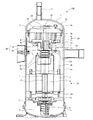
本発明の実施の形態1に係るスクロール圧縮機について説明する。図1は、本発明の実施の形態1に係るスクロール圧縮機100の構成を示す模式的な断面図である。なお、図1では、引き出し線を見やすくするため、断面へのハッチングを省略している。スクロール圧縮機100は、例えば、冷蔵庫、冷凍庫、自動販売機、空気調和機、冷凍機又は給湯装置等に用いられる冷凍サイクル装置の構成要素の1つとなるものである。本実施の形態では、スクロール圧縮機100として、主軸7が鉛直方向に沿って配置される縦置き型のスクロール圧縮機を例示している。なお、以下の説明における各構成部材同士の位置関係(例えば、上下関係等)は、原則として、スクロール圧縮機100を使用可能な状態に設置したときのものである。
Embodiment 1.
The scroll compressor according to Embodiment 1 of the present invention will be described. FIG. 1 is a schematic cross-sectional view showing the configuration of a scroll compressor 100 according to Embodiment 1 of the present invention. In FIG. 1, hatching on the cross section is omitted in order to make it easier to see the lead line. The scroll compressor 100 is one of the components of a refrigeration cycle device used in, for example, a refrigerator, a freezer, a vending machine, an air conditioner, a refrigerator, or a hot water supply device. In the present embodiment, as the scroll compressor 100, a vertical type scroll compressor in which the main shaft 7 is arranged along the vertical direction is illustrated. In addition, the positional relationship (for example, the vertical relationship) between the constituent members in the following description is, in principle, when the scroll compressor 100 is installed in a usable state.

スクロール圧縮機100は、冷凍サイクル装置の冷媒回路を循環する冷媒を吸入して圧縮し、高温高圧の状態にして吐出するものである。冷媒としては、R410A冷媒、R32冷媒又はHFO−1234yf冷媒などが用いられる。 The scroll compressor 100 draws in and compresses the refrigerant circulating in the refrigerant circuit of the refrigeration cycle apparatus, discharges the compressed refrigerant in a high temperature and high pressure state. As the refrigerant, R410A refrigerant, R32 refrigerant, HFO-1234yf refrigerant or the like is used.

図1に示すように、スクロール圧縮機100は、冷媒を圧縮する圧縮機構部20と、圧縮機構部20を駆動する電動機部21と、圧縮機構部20及び電動機部21を収容する密閉容器1と、を有している。圧縮機構部20は、密閉容器1内の上部に配置されている。電動機部21は、密閉容器1内において圧縮機構部20よりも下方に配置されている。 As shown in FIG. 1, the scroll compressor 100 includes a compression mechanism section 20 that compresses a refrigerant, an electric motor section 21 that drives the compression mechanism section 20, and a closed container 1 that houses the compression mechanism section 20 and the electric motor section 21. ,have. The compression mechanism section 20 is arranged in the upper portion of the closed container 1. The electric motor section 21 is arranged below the compression mechanism section 20 in the closed container 1.

密閉容器1は、円筒状の胴部1aと、胴部1aの上端に配置された蓋部1bと、胴部1aの下端に配置された底部1cと、を有している。胴部1aと蓋部1bとの間、及び胴部1aと底部1cとの間は、溶接等により互いに気密に接合されている。 The closed container 1 has a cylindrical body portion 1a, a lid portion 1b arranged at the upper end of the body portion 1a, and a bottom portion 1c arranged at the lower end of the body portion 1a. The body portion 1a and the lid portion 1b, and the body portion 1a and the bottom portion 1c are hermetically joined to each other by welding or the like.

圧縮機構部20は、密閉容器1に取り付けられたフレーム2に固定された固定スクロール3と、固定スクロール3に対して揺動する揺動スクロール4と、を有している。固定スクロール3は、台板3aと、台板3aの一方の面(図1では下面)に設けられた渦巻状のラップ部3bと、を有している。揺動スクロール4は、台板4aと、台板4aの一方の面(図1では上面)に設けられた渦巻状のラップ部4bと、を有している。固定スクロール3及び揺動スクロール4は、それぞれのラップ部3b及びラップ部4bが噛み合うように組み合わされている。ラップ部3bとラップ部4bとの間には、冷媒が圧縮される圧縮室が形成される。 The compression mechanism section 20 has a fixed scroll 3 fixed to a frame 2 attached to the closed container 1, and a swing scroll 4 swinging with respect to the fixed scroll 3. The fixed scroll 3 has a base plate 3a and a spiral wrap portion 3b provided on one surface (the lower surface in FIG. 1) of the base plate 3a. The orbiting scroll 4 has a base plate 4a and a spiral wrap portion 4b provided on one surface (the upper surface in FIG. 1) of the base plate 4a. The fixed scroll 3 and the orbiting scroll 4 are combined so that the respective wrap portions 3b and 4b mesh with each other. A compression chamber in which the refrigerant is compressed is formed between the wrap portion 3b and the wrap portion 4b.

固定スクロール3の台板3aの中心部には、圧縮された冷媒を圧縮室から吐出する吐出ポート22が台板3aを貫通して形成されている。吐出ポート22の出口側には、吐出チャンバ23が設けられている。吐出チャンバ23の吐出口には、リード弁構造の吐出弁24が設けられている。 A discharge port 22 for discharging the compressed refrigerant from the compression chamber is formed at the center of the base plate 3a of the fixed scroll 3 so as to penetrate the base plate 3a. A discharge chamber 23 is provided on the outlet side of the discharge port 22. A discharge valve 24 having a reed valve structure is provided at the discharge port of the discharge chamber 23.

揺動スクロール4の台板4aにおいてラップ部4bが形成された面とは反対側の面(図1では下面)の中心部には、円筒状のボス部4cが形成されている。ボス部4cの内周側には、後述するスライダ30の円筒部40を回転自在に支持する揺動軸受14が設けられている。揺動軸受14の中心軸は、主軸7の中心軸と平行になっている。 A cylindrical boss portion 4c is formed at the center of a surface (lower surface in FIG. 1) of the orbiting scroll 4 opposite to the surface on which the wrap portion 4b is formed. An oscillating bearing 14 that rotatably supports a cylindrical portion 40 of a slider 30 described later is provided on the inner peripheral side of the boss portion 4c. The central axis of the rocking bearing 14 is parallel to the central axis of the main shaft 7.

揺動スクロール4とフレーム2との間には、オルダムリング12が設けられている。オルダムリング12は、リング部と、リング部の上面に形成された一対のオルダムキーと、リング部の下面に形成された一対のオルダムキーと、を有している。上面のオルダムキーは、揺動スクロール4に形成されたキー溝に挿入されており、一方向に摺動自在となっている。下面のオルダムキーは、フレーム2に形成されたキー溝に挿入されており、上記一方向と交差する方向に摺動自在となっている。この構成により、揺動スクロール4は、自転せずに公転運動するようになっている。 An Oldham ring 12 is provided between the orbiting scroll 4 and the frame 2. The Oldham ring 12 has a ring portion, a pair of Oldham keys formed on the upper surface of the ring portion, and a pair of Oldham keys formed on the lower surface of the ring portion. The Oldham key on the upper surface is inserted into a key groove formed in the orbiting scroll 4 and is slidable in one direction. The Oldham key on the lower surface is inserted into a key groove formed in the frame 2 and is slidable in a direction intersecting with the one direction. With this structure, the orbiting scroll 4 revolves around its own axis without rotating.

電動機部21は、密閉容器1の内周に固定されたステータ5と、ステータ5の内周側に配置されたロータ6と、ロータ6に固定された主軸7と、を有している。ステータ5に通電されると、ロータ6は、主軸7と一体となって回転するようになっている。主軸7の上部は、フレーム2に設けられた主軸受部16に回転自在に支持されている。主軸7の下部は、ボールベアリング等により構成された副軸受部17に回転自在に支持されている。この副軸受部17は、密閉容器1の下部に固定されたサブフレーム18に設けられている。 The electric motor unit 21 has a stator 5 fixed to the inner circumference of the closed casing 1, a rotor 6 arranged on the inner circumference side of the stator 5, and a main shaft 7 fixed to the rotor 6. When the stator 5 is energized, the rotor 6 rotates together with the main shaft 7. The upper portion of the main shaft 7 is rotatably supported by a main bearing portion 16 provided on the frame 2. A lower portion of the main shaft 7 is rotatably supported by a sub bearing portion 17 formed of a ball bearing or the like. The sub bearing portion 17 is provided on a sub frame 18 fixed to the lower portion of the closed container 1.

主軸7の上端部には、偏芯軸部7aが設けられている。偏芯軸部7aは、主軸7の中心軸に対して所定の偏芯方向に偏芯して配置されている。偏芯軸部7aは、後述するスライダ30のスライド溝43に摺動自在に挿入されている。 An eccentric shaft portion 7a is provided at the upper end of the main shaft 7. The eccentric shaft portion 7a is arranged eccentrically in a predetermined eccentric direction with respect to the central axis of the main shaft 7. The eccentric shaft portion 7a is slidably inserted in a slide groove 43 of a slider 30 described later.

密閉容器1の底部には、潤滑油を貯留する油溜め8が設けられている。主軸7の下端には、油溜め8の潤滑油を吸い上げるオイルポンプ9が設けられている。主軸7の内部には、主軸7の中心軸方向に沿って油穴13が形成されている。オイルポンプ9によって油溜め8から吸い上げられた潤滑油は、油穴13を通って、揺動軸受14を含む各摺動部に供給されるようになっている。また、フレーム2には、フレーム2内の潤滑油を油溜め8に戻す排油パイプ15が接続されている。 An oil sump 8 for storing lubricating oil is provided at the bottom of the closed container 1. At the lower end of the main shaft 7, an oil pump 9 that sucks up the lubricating oil in the oil sump 8 is provided. An oil hole 13 is formed inside the main shaft 7 along the central axis direction of the main shaft 7. The lubricating oil sucked up from the oil sump 8 by the oil pump 9 passes through the oil hole 13 and is supplied to each sliding portion including the rocking bearing 14. Further, the frame 2 is connected to an oil drain pipe 15 that returns the lubricating oil in the frame 2 to the oil sump 8.

主軸7の上部には、揺動スクロール4の揺動によるアンバランスを相殺する第1バランサ19aが設けられている。ロータ6の下部には、揺動スクロール4の揺動によるアンバランスを相殺する第2バランサ19bが設けられている。 A first balancer 19a is provided on the upper portion of the main shaft 7 to cancel the unbalance due to the swing of the swing scroll 4. A second balancer 19b is provided below the rotor 6 to cancel the unbalance due to the swing of the swing scroll 4.

また、密閉容器1には、外部から低圧のガス冷媒を吸入する吸入管10と、圧縮された高圧のガス冷媒を外部に吐出する吐出管11と、が設けられている。 Further, the closed container 1 is provided with a suction pipe 10 for sucking a low-pressure gas refrigerant from the outside and a discharge pipe 11 for discharging a compressed high-pressure gas refrigerant to the outside.

ここで、スクロール圧縮機100の全体的な動作を簡単に説明する。ステータ5に通電されると、ロータ6が回転する。ロータ6の回転駆動力は、主軸7、偏芯軸部7a及びスライダ30を介して揺動スクロール4に伝達される。回転駆動力が伝達された揺動スクロール4は、オルダムリング12により自転を規制され、固定スクロール3に対して公転運動を行う。 Here, the overall operation of the scroll compressor 100 will be briefly described. When the stator 5 is energized, the rotor 6 rotates. The rotational driving force of the rotor 6 is transmitted to the orbiting scroll 4 via the main shaft 7, the eccentric shaft portion 7 a, and the slider 30. The orbiting scroll 4 to which the rotational driving force is transmitted is restricted from rotating by the Oldham ring 12 and revolves with respect to the fixed scroll 3.

揺動スクロール4の公転運動に伴い、吸入管10から密閉容器1内に吸入された低圧のガス冷媒は、フレーム2に形成された不図示の吸入ポートを通って圧縮室に取り込まれ、圧縮室内で圧縮される。圧縮された高圧のガス冷媒は、吐出ポート22を介して吐出チャンバ23内に吐出される。吐出チャンバ23内の高圧のガス冷媒は、吐出弁24を押し上げて固定スクロール3と密閉容器1との間の高圧空間に吐出された後、吐出管11からスクロール圧縮機100の外部に吐出される。 The low-pressure gas refrigerant sucked into the closed container 1 from the suction pipe 10 along with the orbiting movement of the orbiting scroll 4 is taken into the compression chamber through a suction port (not shown) formed in the frame 2, and the compression chamber is compressed. Compressed with. The compressed high-pressure gas refrigerant is discharged into the discharge chamber 23 via the discharge port 22. The high-pressure gas refrigerant in the discharge chamber 23 pushes up the discharge valve 24 to be discharged into the high-pressure space between the fixed scroll 3 and the closed container 1, and then is discharged from the discharge pipe 11 to the outside of the scroll compressor 100. ..

次に、本実施の形態の前提となるスライダ30について説明する。ここで説明するスライダ30は、当該スライダ30の遠心力作用中心の軸方向位置が当該スライダ30と揺動軸受14との回転摺動範囲の中央部の軸方向位置に一致した構成を有するバランスウエイト付きスライダの一例である。 Next, the slider 30 which is the premise of the present embodiment will be described. The slider 30 described here has a configuration in which the axial position of the centrifugal force action center of the slider 30 matches the axial position of the central portion of the rotary sliding range between the slider 30 and the rocking bearing 14. It is an example of an attached slider.

図2は、本実施の形態の前提となるスライダ30の構成を示す上面図である。図3は、図2のIII−III断面を示す断面図である。図4は、本実施の形態の前提となるスライダ30を備えたスクロール圧縮機の要部構成を示す断面図である。図4では、スライダ30に作用する遠心力の位置及び油膜反力の作用位置を模式的に表している。図2〜図4の白抜き矢印Aは、主軸7の中心軸に対する偏芯軸部7aの偏芯方向、つまり主軸7の中心軸に対する揺動軸受14の偏芯方向を示している。また、図2〜図4の白抜き矢印Bは、上記の偏芯方向とは逆方向となる反偏芯方向を示している。偏芯方向及び反偏芯方向は、主軸7の中心軸と垂直な方向である。ここで、偏芯方向及び反偏芯方向と平行にY軸をとり、偏芯方向側を+Y方向とする。また、主軸7の中心軸と平行な方向、つまり鉛直方向にZ軸をとり、上側を+Z方向とする。 FIG. 2 is a top view showing the configuration of the slider 30 which is the premise of the present embodiment. FIG. 3 is a cross-sectional view showing a III-III cross section of FIG. 2. FIG. 4 is a cross-sectional view showing a main configuration of a scroll compressor provided with the slider 30 which is the premise of the present embodiment. In FIG. 4, the position of the centrifugal force acting on the slider 30 and the position of the oil film reaction force are schematically shown. 2 to 4 indicate an eccentric direction of the eccentric shaft portion 7a with respect to the central axis of the main shaft 7, that is, an eccentric direction of the rocking bearing 14 with respect to the central axis of the main shaft 7. In addition, a white arrow B in FIGS. 2 to 4 indicates an anti-eccentric direction which is a direction opposite to the above-mentioned eccentric direction. The eccentric direction and the anti-eccentric direction are directions perpendicular to the central axis of the main shaft 7. Here, the Y axis is taken parallel to the eccentric direction and the anti-eccentric direction, and the eccentric direction side is defined as the +Y direction. Further, the Z axis is taken in the direction parallel to the central axis of the main shaft 7, that is, the vertical direction, and the upper side is defined as the +Z direction.

スライダ30は、揺動スクロール4の公転半径を固定スクロール3のラップ部3bの側面形状に沿って可変とする可変クランク機構を構成するものである。スライダ30は、揺動軸受14に回転自在に支持される円筒部40と、揺動スクロール4に作用する遠心力の少なくとも一部を相殺するバランスウエイト部50と、を有している。このスライダ30は、フレーム2に形成された凹部2a内に収納されている。スライダ30の回転中心Oは、主軸7の中心軸と一致している。なお、円筒部40とバランスウエイト部50との接続構成は任意である。例えば、円筒部40とバランスウエイト部50とを別部品として成型した後、両者を互いに固定することにより、円筒部40とバランスウエイト部50とを接続してもよい。円筒部40とバランスウエイト部50とは、例えば、焼嵌め又は圧入等の手段を用いて固定することができる。 The slider 30 constitutes a variable crank mechanism that makes the revolution radius of the orbiting scroll 4 variable along the side surface shape of the wrap portion 3b of the fixed scroll 3. The slider 30 includes a cylindrical portion 40 that is rotatably supported by the swing bearing 14, and a balance weight portion 50 that cancels at least a part of the centrifugal force that acts on the swing scroll 4. The slider 30 is housed in a recess 2 a formed in the frame 2. The rotation center O of the slider 30 coincides with the center axis of the main shaft 7. The connection configuration between the cylindrical portion 40 and the balance weight portion 50 is arbitrary. For example, the cylindrical portion 40 and the balance weight portion 50 may be molded as separate parts and then fixed to each other to connect the cylindrical portion 40 and the balance weight portion 50. The cylindrical portion 40 and the balance weight portion 50 can be fixed to each other using, for example, shrink fitting or press fitting.

円筒部40は、外径Dsの円筒面状の外周面を備えている。この外周面は、揺動軸受14に対する摺動面となる。円筒部40の中心軸C1は、スライダ30の回転中心Oから偏芯方向、つまり+Y方向に距離y3だけ離れた位置に設けられている。円筒部40の内周側には、長穴形状の断面を有するスライド溝43が形成されている。スライド溝43には、偏芯軸部7aが挿入される。スライド溝43に挿入された偏芯軸部7aは、スライド溝43に対し、回転中心Oに垂直な所定の摺動方向に摺動自在となる。本例では、偏芯軸部7aとスライド溝43との摺動方向は、偏芯軸部7aの偏芯方向に対して傾いている。 The cylindrical portion 40 includes a cylindrical outer peripheral surface having an outer diameter Ds. The outer peripheral surface serves as a sliding surface for the rocking bearing 14. The central axis C1 of the cylindrical portion 40 is provided at a position separated from the rotation center O of the slider 30 by a distance y3 in the eccentric direction, that is, the +Y direction. A slide groove 43 having an elongated hole-shaped cross section is formed on the inner peripheral side of the cylindrical portion 40. The eccentric shaft portion 7a is inserted into the slide groove 43. The eccentric shaft portion 7a inserted into the slide groove 43 is slidable with respect to the slide groove 43 in a predetermined sliding direction perpendicular to the rotation center O. In this example, the sliding direction of the eccentric shaft portion 7a and the slide groove 43 is inclined with respect to the eccentric direction of the eccentric shaft portion 7a.

バランスウエイト部50は、平板部51及び突出部52を備えている。平板部51は、円筒部40の外周部を取り巻くように配置された厚さH2の略円盤形状部分であり、円筒部40に接続されている。図1及び図4に示すように、円筒部40の上部は、揺動軸受14に挿入される。このため、円筒部40と平板部51とは、Z軸方向において揺動軸受14の先端よりも揺動スクロール4から離れた位置で、つまり揺動軸受14の下端よりも下方となる位置で接続されている。突出部52は、平板部51から揺動スクロール4側へ、つまり上方へ突出した突出部分である。この突出部52は、スライダ30の回転中心Oよりも反偏芯方向側に配置されている。また、突出部52は、揺動軸受14及びボス部4cとの干渉を避けるため、円筒部40の中心軸C1から半径Rin離れた位置に配置されている。 The balance weight portion 50 includes a flat plate portion 51 and a protruding portion 52. The flat plate portion 51 is a substantially disc-shaped portion having a thickness H2 arranged so as to surround the outer peripheral portion of the cylindrical portion 40, and is connected to the cylindrical portion 40. As shown in FIGS. 1 and 4, the upper portion of the cylindrical portion 40 is inserted into the rocking bearing 14. Therefore, the cylindrical portion 40 and the flat plate portion 51 are connected to each other in the Z-axis direction at a position farther from the orbiting scroll 4 than the tip of the orbiting bearing 14, that is, at a position below the lower end of the orbiting bearing 14. Has been done. The protruding portion 52 is a protruding portion protruding from the flat plate portion 51 toward the orbiting scroll 4, that is, upward. The protruding portion 52 is arranged on the side opposite to the eccentric direction with respect to the rotation center O of the slider 30. Further, the protruding portion 52 is arranged at a position separated from the central axis C1 of the cylindrical portion 40 by the radius Rin in order to avoid interference with the swing bearing 14 and the boss portion 4c.

バランスウエイト部50は全体として、揺動スクロール4の遠心力を相殺するために、回転中心Oよりも反偏芯方向側に偏芯して設けられている。バランスウエイト部50の遠心力によって揺動スクロール4の遠心力の少なくとも一部が相殺されることにより、揺動スクロール4のラップ部4bに作用する半径方向の荷重が低減される。このため、揺動スクロール4の信頼性を向上できるとともに、揺動スクロール4のラップ部4bと固定スクロール3のラップ部3bとの間の摺動損失を低減できる。 The balance weight portion 50 is provided eccentrically on the anti-eccentric direction side of the rotation center O in order to cancel the centrifugal force of the orbiting scroll 4 as a whole. At least part of the centrifugal force of the orbiting scroll 4 is canceled by the centrifugal force of the balance weight portion 50, so that the radial load acting on the wrap portion 4b of the orbiting scroll 4 is reduced. Therefore, the reliability of the orbiting scroll 4 can be improved, and the sliding loss between the wrap portion 4b of the orbiting scroll 4 and the wrap portion 3b of the fixed scroll 3 can be reduced.

ここで、スライダ30が回転した際に揺動軸受14とスライダ30の円筒部40外周面との間に発生する油膜反力の作用中心は、図4の白抜き矢印Eに示すように、揺動軸受14のZ軸方向の中心となる。このため、Z軸方向において、スライダ30の遠心力作用中心の位置が揺動軸受14の中心位置からずれていると、油膜反力の作用中心と遠心力の作用中心とを一致させるためにスライダ30が転覆しようとする。これにより、スライダ30の円筒部40と揺動軸受14との間で片当たりが発生する。したがって、Z軸方向においてスライダ30の遠心力作用中心の位置と揺動軸受14の中心位置とが略一致する形状となるように、スライダ30を設計する必要がある。 Here, the action center of the oil film reaction force generated between the oscillating bearing 14 and the outer peripheral surface of the cylindrical portion 40 of the slider 30 when the slider 30 rotates, as shown by the white arrow E in FIG. It is the center of the dynamic bearing 14 in the Z-axis direction. Therefore, when the position of the centrifugal force acting center of the slider 30 deviates from the center position of the rocking bearing 14 in the Z-axis direction, the action center of the oil film reaction force coincides with the action center of the centrifugal force. 30 tries to capsize. As a result, partial contact occurs between the cylindrical portion 40 of the slider 30 and the rocking bearing 14. Therefore, it is necessary to design the slider 30 so that the position of the centrifugal force acting center of the slider 30 and the center position of the rocking bearing 14 in the Z-axis direction substantially match.

しかしながら、スライダ30を設計する際には、以下のような制約がある。すなわち、スライダ30の円筒部40とバランスウエイト部50とは、揺動軸受14及びボス部4cと干渉しない箇所で接続されなければならない。換言すると、円筒部40とバランスウエイト部50とを接続する接続部は、揺動軸受14及びボス部4cと干渉しない箇所に配置されることになる。縦置き型のスクロール圧縮機100の場合、スライダ30の円筒部40とバランスウエイト部50とを接続する接続部は、揺動軸受14の下方に配置される。この接続部は、バランスウエイト部50に発生する遠心力を支持するため、強度上ある程度の肉厚で形成される必要がある。このため、スライダ30全体としての遠心力作用中心の高さは、上記の接続部に発生する遠心力により、下方に下がる傾向になる。したがって、スライダ30の遠心力作用中心の位置と揺動軸受14の中心位置とを略一致させるには、スライダ30の遠心力作用中心を上方に引き上げる工夫が必要となる。 However, there are the following restrictions when designing the slider 30. That is, the cylindrical portion 40 of the slider 30 and the balance weight portion 50 must be connected at a location where they do not interfere with the rocking bearing 14 and the boss portion 4c. In other words, the connecting portion that connects the cylindrical portion 40 and the balance weight portion 50 is arranged at a position that does not interfere with the rocking bearing 14 and the boss portion 4c. In the case of the vertical scroll compressor 100, the connecting portion that connects the cylindrical portion 40 of the slider 30 and the balance weight portion 50 is arranged below the rocking bearing 14. The connecting portion supports the centrifugal force generated in the balance weight portion 50, and therefore needs to be formed with a certain thickness in terms of strength. Therefore, the height of the centrifugal force acting center of the slider 30 as a whole tends to be lowered due to the centrifugal force generated at the connection portion. Therefore, in order to make the position of the center of action of the centrifugal force of the slider 30 and the position of the center of the rocking bearing 14 substantially coincide with each other, it is necessary to devise to pull the center of action of the centrifugal force of the slider 30 upward.

図2〜図4に示すスライダ30におけるバランスウエイト部50は、スライダ30の回転中心Oよりも反偏芯方向側に設けられたメインウエイト部53と、スライダ30の回転中心Oよりも偏芯方向側に設けられたカウンタウエイト部54と、を備えている。また、本実施の形態1では、メインウエイト部53は、第1メインウエイト部53a及び第2メインウエイト部53bを備えている。 The balance weight portion 50 in the slider 30 shown in FIGS. 2 to 4 includes a main weight portion 53 provided on the side opposite to the center of rotation O of the slider 30 in the direction of eccentricity, and a direction of eccentricity relative to the center of rotation O of the slider 30. And a counterweight portion 54 provided on the side. In addition, in the first embodiment, the main weight portion 53 includes a first main weight portion 53a and a second main weight portion 53b.

カウンタウエイト部54は、平板部51のうち、スライダ30の回転中心Oよりも偏芯方向側に設けられた部分により構成される。カウンタウエイト部54は、Z軸方向において揺動軸受14よりも揺動スクロール4から離れた位置に、つまり揺動軸受14のZ軸方向の中心位置よりも揺動スクロール4から離れた位置に配置されている。カウンタウエイト部54は、円筒部40の中心軸C1を中心とする半径R3の部分円筒面状の外周面を有している。 The counterweight portion 54 is configured by a portion of the flat plate portion 51 provided on the eccentric direction side of the rotation center O of the slider 30. The counterweight portion 54 is arranged at a position farther from the rocking scroll 4 than the rocking bearing 14 in the Z-axis direction, that is, at a position farther from the rocking scroll 4 than the center position of the rocking bearing 14 in the Z-axis direction. Has been done. The counterweight portion 54 has an outer peripheral surface having a partially cylindrical surface shape with a radius R3 centered on the central axis C1 of the cylindrical portion 40.

第1メインウエイト部53aは、平板部51のうちのスライダ30の回転中心Oよりも反偏芯方向側に設けられた部分と、突出部52の下部部分と、により構成される。第1メインウエイト部53aは、第2メインウエイト部53bよりも揺動スクロール4から離れた位置に配置されている。第1メインウエイト部53aは、スライダ30の回転中心Oから+Y方向に距離y2だけ離れた位置を中心とする、半径R2の部分円筒面状の外周面を有している。ここで、距離y2は距離y3よりも小さい(y2<y3)。 The first main weight portion 53a is configured by a portion of the flat plate portion 51 provided on the side of the slider 30 opposite to the center of rotation O of the slider 30 and a lower portion of the protruding portion 52. The first main weight portion 53a is located farther from the orbiting scroll 4 than the second main weight portion 53b. The first main weight portion 53a has a partially cylindrical outer peripheral surface having a radius R2 centered on a position separated from the rotation center O of the slider 30 in the +Y direction by a distance y2. Here, the distance y2 is smaller than the distance y3 (y2<y3).

第2メインウエイト部53bは、突出部52の上部部分により構成される。全高Hのメインウエイト部53のうち上端から高さH1の範囲が第2メインウエイト部53bとなる。第2メインウエイト部53bは、第1メインウエイト部53aよりも揺動スクロール4側に配置されている。第2メインウエイト部53bは、スライダ30の回転中心Oを中心とする半径R1の部分円筒面状の外周面を有している。また、第2メインウエイト部53bは、円筒部40の中心軸C1を中心とする半径Rinの部分円筒面状の内周面を有している。 The second main weight portion 53b is configured by the upper portion of the protruding portion 52. The area of the height H1 from the upper end of the main weight portion 53 having the total height H is the second main weight portion 53b. The second main weight portion 53b is arranged closer to the orbiting scroll 4 than the first main weight portion 53a. The second main weight portion 53b has a partially cylindrical outer peripheral surface having a radius R1 centered on the rotation center O of the slider 30. In addition, the second main weight portion 53b has a partially cylindrical inner surface having a radius Rin centered on the central axis C1 of the cylindrical portion 40.

第2メインウエイト部53bの外周面は、第1メインウエイト部53aの外周面よりも外周側に位置している。これにより、第2メインウエイト部53bの単位厚さ当たりの遠心力(断面積×図芯距離)が、第1メインウエイト部53aの単位厚さ当たりの遠心力(断面積×図芯距離)よりも大きくなる。このため、メインウエイト部53に発生する遠心力のZ軸方向の作用中心を、揺動スクロール4側つまり上方に引き上げることができる。したがって、図2〜図4に示すスライダ30によれば、Z軸方向において、図4の黒塗り矢印Fで示すスライダ30の遠心力作用中心の位置と、図4の白抜き矢印Eで示す油膜反力の作用中心とを略一致させることが可能となる。よって、スライダ30の円筒部40と揺動軸受14との間で片当たりが発生するのを防ぐことができる。また、スライダ30の軸方向寸法及び径方向寸法の増加が抑えられるため、スライダ30を小型化できる。 The outer peripheral surface of the second main weight portion 53b is located on the outer peripheral side of the outer peripheral surface of the first main weight portion 53a. Thereby, the centrifugal force per unit thickness of the second main weight portion 53b (cross-sectional area x centroid distance) is smaller than the centrifugal force per unit thickness of the first main weight portion 53a (cross-sectional area x centroid distance). Also grows. Therefore, the center of action of the centrifugal force generated in the main weight portion 53 in the Z-axis direction can be pulled up to the side of the orbiting scroll 4, that is, upward. Therefore, according to the slider 30 shown in FIGS. 2 to 4, in the Z-axis direction, the position of the centrifugal force acting center of the slider 30 shown by the black arrow F in FIG. 4 and the oil film shown by the white arrow E in FIG. It becomes possible to make the action center of the reaction force substantially coincide with each other. Therefore, it is possible to prevent uneven contact between the cylindrical portion 40 of the slider 30 and the rocking bearing 14. Further, since the increase in the axial dimension and the radial dimension of the slider 30 is suppressed, the slider 30 can be downsized.

しかしながら、図2〜図4に示すスライダ30では、研削工程又は研磨工程でスライダ30の各円筒面を加工する際に多数の加工中心軸が必要となる。例えば、カウンタウエイト部54の外周面及び第2メインウエイト部53bの内周面を加工する際には、円筒部40の中心軸C1となる位置が加工中心軸となる。第1メインウエイト部53aの外周面を加工する際には、スライダ30の回転中心Oから+Y方向に距離y2だけ離れた位置が加工中心軸となる。第2メインウエイト部53bの外周面を加工する際には、スライダ30の回転中心Oとなる位置が加工中心軸となる。すなわち、図2〜図4に示すスライダ30のバランスウエイト部50は、少なくとも3つの加工中心軸を有する。したがって、図2〜図4に示すスライダ30には、スライダ30の加工工程が増加し、それに伴いスライダ30の加工コスト及びスクロール圧縮機100の製造コストが増加してしまうという課題があった。 However, in the slider 30 shown in FIGS. 2 to 4, a large number of processing center axes are required when processing each cylindrical surface of the slider 30 in the grinding process or the polishing process. For example, when processing the outer peripheral surface of the counterweight portion 54 and the inner peripheral surface of the second main weight portion 53b, the position serving as the central axis C1 of the cylindrical portion 40 becomes the processing central axis. When machining the outer peripheral surface of the first main weight portion 53a, the machining center axis is a position separated from the rotation center O of the slider 30 by a distance y2 in the +Y direction. When processing the outer peripheral surface of the second main weight portion 53b, the position serving as the rotation center O of the slider 30 becomes the processing center axis. That is, the balance weight portion 50 of the slider 30 shown in FIGS. 2 to 4 has at least three processing center axes. Therefore, the slider 30 shown in FIGS. 2 to 4 has a problem that the processing steps of the slider 30 are increased, and accordingly, the processing cost of the slider 30 and the manufacturing cost of the scroll compressor 100 are increased.

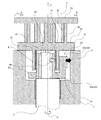
以下、上記課題を解決できる本実施の形態に係るスライダ30について説明する。図5は、本実施の形態に係るスクロール圧縮機100のスライダ30の構成を示す上面図である。図6は、図5のVI−VI断面を示す断面図である。以下の説明では、スライダ30の位置を基準として、揺動スクロール4側の方向を上方といい、揺動スクロール4から離れる方向を下方という場合がある。図5及び図6に示すように、スライダ30は、揺動軸受14に回転自在に支持される円筒部40と、円筒部40の外周側に設けられたバランスウエイト部50と、を有している。円筒部40とバランスウエイト部50とは、別体として成型された別部品であり、焼嵌め又は圧入等により互いに固定されている。 Hereinafter, the slider 30 according to the present embodiment that can solve the above problems will be described. FIG. 5 is a top view showing the configuration of the slider 30 of the scroll compressor 100 according to this embodiment. FIG. 6 is a cross-sectional view showing a VI-VI cross section of FIG. In the following description, with respect to the position of the slider 30, the direction on the orbiting scroll 4 side may be referred to as upward, and the direction away from the orbiting scroll 4 may be referred to as downward. As shown in FIGS. 5 and 6, the slider 30 has a cylindrical portion 40 rotatably supported by the rocking bearing 14 and a balance weight portion 50 provided on the outer peripheral side of the cylindrical portion 40. There is. The cylindrical portion 40 and the balance weight portion 50 are separate components molded as separate bodies, and are fixed to each other by shrink fitting or press fitting.

円筒部40は、図2〜図4に示した円筒部40と同様の構成を有している。バランスウエイト部50は、カウンタウエイト部54と、第1メインウエイト部53a及び第2メインウエイト部53bを備えたメインウエイト部53と、を有している。バランスウエイト部50は、鋳造又は鍛造により形成されている。円筒部40の外周面41に固定されるバランスウエイト部50の内周面は、円筒部40の中心軸C1を中心とする円筒面状の形状を有している。 The cylindrical portion 40 has the same configuration as the cylindrical portion 40 shown in FIGS. The balance weight section 50 includes a counter weight section 54 and a main weight section 53 including a first main weight section 53a and a second main weight section 53b. The balance weight portion 50 is formed by casting or forging. The inner peripheral surface of the balance weight portion 50 fixed to the outer peripheral surface 41 of the cylindrical portion 40 has a cylindrical surface shape centered on the central axis C1 of the cylindrical portion 40.

カウンタウエイト部54は、スライダ30の回転中心Oよりも偏芯方向側に設けられており、円筒部40の外周面41下部に固定されている。カウンタウエイト部54は、スライダ30の回転中心Oを中心とする直径D1すなわち半径D1/2の部分円筒面状の外周面61(第1外周面の一例)を有している。 The counterweight portion 54 is provided on the eccentric direction side of the rotation center O of the slider 30, and is fixed to the lower portion of the outer peripheral surface 41 of the cylindrical portion 40. The counterweight portion 54 has a partially cylindrical outer peripheral surface 61 (an example of a first outer peripheral surface) having a diameter D1 around the rotation center O of the slider 30, that is, a radius D1/2.

第1メインウエイト部53aは、スライダ30の回転中心Oよりも反偏芯方向側に設けられており、円筒部40の外周面41下部に固定されている。第1メインウエイト部53aは、スライダ30の回転中心Oを中心とする直径D1すなわち半径D1/2の部分円筒面状の外周面64を有している。本実施の形態では、第1メインウエイト部53aの外周面64は、カウンタウエイト部54の外周面61と同軸かつ同一半径で形成されている。このため、第1メインウエイト部53aの外周面64は、カウンタウエイト部54の外周面61と連続した円筒面を構成している。ただし、第1メインウエイト部53aの外周面64の半径は、カウンタウエイト部54の外周面61の半径と異なっていてもよい。 The first main weight portion 53 a is provided on the side opposite to the eccentric direction with respect to the rotation center O of the slider 30, and is fixed to the lower portion of the outer peripheral surface 41 of the cylindrical portion 40. The first main weight portion 53a has a partially cylindrical outer peripheral surface 64 having a diameter D1 with the rotation center O of the slider 30 as the center, that is, a radius D1/2. In the present embodiment, the outer peripheral surface 64 of the first main weight portion 53a is formed coaxially and with the same radius as the outer peripheral surface 61 of the counterweight portion 54. For this reason, the outer peripheral surface 64 of the first main weight portion 53a constitutes a cylindrical surface that is continuous with the outer peripheral surface 61 of the counterweight portion 54. However, the radius of the outer peripheral surface 64 of the first main weight portion 53a may be different from the radius of the outer peripheral surface 61 of the counterweight portion 54.

また、第1メインウエイト部53aは、周方向の少なくとも一部に、円筒部40の中心軸C1を中心とする半径R4の部分円筒面状の外周面62(第2外周面の一例)を有している。スライダ30の回転中心Oに沿う方向に見ると、外周面62は、回転中心Oを通り偏芯方向に平行な直線を対称軸として、線対称となるように形成されている。本例の外周面62は、回転中心Oに沿う方向に見たとき、回転中心Oを通り偏芯方向に平行な直線を中心とした約90°の角度範囲に、概ね扇形状に形成されている。また、外周面62は、メインウエイト部53の下端面53cから高さH3の範囲に形成されている。外周面62は、外周面64及び後述する外周面63よりも内周側に位置している。したがって、外周面62は、外周面64及び外周面63に対して径方向内側に凹んだ凹部を構成する。 Further, the first main weight portion 53a has a partially cylindrical outer peripheral surface 62 (an example of a second outer peripheral surface) having a radius R4 centered on the central axis C1 of the cylindrical portion 40 in at least a part of the circumferential direction. doing. When viewed in the direction along the rotation center O of the slider 30, the outer peripheral surface 62 is formed to be line-symmetrical about a straight line that passes through the rotation center O and is parallel to the eccentric direction. The outer peripheral surface 62 of this example is formed in a substantially fan shape in an angle range of about 90° about a straight line passing through the rotation center O and parallel to the eccentric direction when viewed in the direction along the rotation center O. There is. The outer peripheral surface 62 is formed in a range of height H3 from the lower end surface 53c of the main weight portion 53. The outer peripheral surface 62 is located on the inner peripheral side with respect to the outer peripheral surface 64 and an outer peripheral surface 63 described later. Therefore, the outer peripheral surface 62 constitutes a concave portion that is recessed radially inward with respect to the outer peripheral surface 64 and the outer peripheral surface 63.

第2メインウエイト部53bは、スライダ30の回転中心Oよりも反偏芯方向側に設けられており、第1メインウエイト部53aの外周部から揺動スクロール4側に突出して形成されている。第2メインウエイト部53bは、スライダ30の回転中心Oを中心とする直径D1すなわち半径D1/2の部分円筒面状の外周面63(第3外周面の一例)を有している。本実施の形態では、第2メインウエイト部53bの外周面63は、第1メインウエイト部53aの外周面64及びカウンタウエイト部54の外周面61の双方と同軸かつ同一半径で形成されている。このため、第2メインウエイト部53bの外周面63は、第1メインウエイト部53aの外周面64及びカウンタウエイト部54の外周面61の双方と連続した円筒面を構成している。ただし、第2メインウエイト部53bの外周面63の半径は、第1メインウエイト部53aの外周面64の半径と異なっていてもよいし、カウンタウエイト部54の外周面61の半径と異なっていてもよい。 The second main weight portion 53b is provided on the side opposite to the center of rotation O of the slider 30 in the eccentric direction, and is formed so as to project from the outer peripheral portion of the first main weight portion 53a toward the orbiting scroll 4. The second main weight portion 53b has a partially cylindrical outer peripheral surface 63 (an example of a third outer peripheral surface) having a diameter D1 centering on the rotation center O of the slider 30 or a radius D1/2. In the present embodiment, the outer peripheral surface 63 of the second main weight portion 53b is formed coaxially and with the same radius as both the outer peripheral surface 64 of the first main weight portion 53a and the outer peripheral surface 61 of the counterweight portion 54. Therefore, the outer peripheral surface 63 of the second main weight portion 53b forms a cylindrical surface that is continuous with both the outer peripheral surface 64 of the first main weight portion 53a and the outer peripheral surface 61 of the counterweight portion 54. However, the radius of the outer peripheral surface 63 of the second main weight portion 53b may be different from the radius of the outer peripheral surface 64 of the first main weight portion 53a, or different from the radius of the outer peripheral surface 61 of the counterweight portion 54. Good.

また、第2メインウエイト部53bは、円筒部40の中心軸C1を中心とする半径Rinの部分円筒面状の内周面65を有している。第2メインウエイト部53bの内周面65は、ボス部4c及び揺動軸受14を挟んで円筒部40の外周面41と対向する。 The second main weight portion 53b has an inner peripheral surface 65 having a partial cylindrical surface shape with a radius Rin centered on the central axis C1 of the cylindrical portion 40. The inner peripheral surface 65 of the second main weight portion 53b faces the outer peripheral surface 41 of the cylindrical portion 40 with the boss portion 4c and the rocking bearing 14 interposed therebetween.

以上説明したように、本実施の形態に係るスクロール圧縮機100は、固定スクロール3と、固定スクロール3に対して揺動する揺動スクロール4と、揺動スクロール4に回転駆動力を伝達する主軸7と、主軸7の一端に設けられ、主軸7の中心軸に対して偏芯方向に偏芯した偏芯軸部7aと、偏芯軸部7aが摺動自在に挿入されるスライド溝43が形成されたスライダ30と、揺動スクロール4に設けられ、スライダ30を回転自在に支持する揺動軸受14と、を備えている。スライダ30は、揺動軸受14に回転自在に支持される円筒部40と、円筒部40の外周側に設けられたバランスウエイト部50と、を有している。偏芯方向の逆方向を反偏芯方向としたとき、バランスウエイト部50は、スライダ30の回転中心Oよりも偏芯方向側に設けられ、円筒部40に接続されたカウンタウエイト部54と、スライダ30の回転中心Oよりも反偏芯方向側に設けられ、円筒部40に接続された第1メインウエイト部53aと、スライダ30の回転中心Oよりも反偏芯方向側に設けられ、第1メインウエイト部53aの外周部から揺動スクロール4側に突出した第2メインウエイト部53bと、を有している。カウンタウエイト部54は、スライダ30の回転中心Oを中心とする部分円筒面状の外周面61を有している。第1メインウエイト部53aは、円筒部40の中心軸C1を中心とする部分円筒面状の外周面62を有している。第2メインウエイト部53bは、外周面62よりも外周側に位置し、スライダ30の回転中心Oを中心とする部分円筒面状の外周面63と、円筒部40の中心軸C1を中心とする部分円筒面状の内周面65と、を有している。 As described above, the scroll compressor 100 according to the present embodiment includes the fixed scroll 3, the orbiting scroll 4 that swings with respect to the fixed scroll 3, and the main shaft that transmits the rotational driving force to the orbiting scroll 4. 7, an eccentric shaft portion 7a provided at one end of the main shaft 7 and eccentric in the eccentric direction with respect to the central axis of the main shaft 7, and a slide groove 43 into which the eccentric shaft portion 7a is slidably inserted. The slider 30 formed is provided with an oscillating bearing 14 that is provided on the oscillating scroll 4 and rotatably supports the slider 30. The slider 30 has a cylindrical portion 40 rotatably supported by the rocking bearing 14 and a balance weight portion 50 provided on the outer peripheral side of the cylindrical portion 40. When the direction opposite to the eccentric direction is defined as the anti-eccentric direction, the balance weight portion 50 is provided on the eccentric direction side with respect to the rotation center O of the slider 30, and the counterweight portion 54 connected to the cylindrical portion 40, The first main weight portion 53a is provided on the anti-eccentric direction side of the rotation center O of the slider 30 and connected to the cylindrical portion 40, and is provided on the anti-eccentric direction side of the rotation center O of the slider 30. The first main weight portion 53a has a second main weight portion 53b protruding from the outer peripheral portion toward the orbiting scroll 4 side. The counterweight portion 54 has a partially cylindrical outer peripheral surface 61 centered on the rotation center O of the slider 30. The first main weight portion 53a has an outer peripheral surface 62 having a partially cylindrical surface centered on the central axis C1 of the cylindrical portion 40. The second main weight portion 53b is located on the outer peripheral side of the outer peripheral surface 62, and has an outer peripheral surface 63 having a partially cylindrical surface centered on the rotation center O of the slider 30 and a central axis C1 of the cylindrical portion 40. And an inner peripheral surface 65 having a partially cylindrical surface shape.

カウンタウエイト部54の外周面61及び第2メインウエイト部53bの外周面63を加工する際には、スライダ30の回転中心Oとなる位置が加工中心軸となる。また、第1メインウエイト部53aの外周面62及び第2メインウエイト部53bの内周面65を加工する際には、円筒部40の中心軸C1となる位置が加工中心軸となる。このため、本実施の形態では、バランスウエイト部50の各円筒面を加工する際に必要な加工中心軸の数を2つにすることができる。したがって、本実施の形態によれば、スライダ30の加工工程を削減することができ、それに伴いスライダ30の加工コスト及びスクロール圧縮機100の製造コストを削減することができる。 When processing the outer peripheral surface 61 of the counterweight portion 54 and the outer peripheral surface 63 of the second main weight portion 53b, the position serving as the rotation center O of the slider 30 becomes the processing center axis. Further, when processing the outer peripheral surface 62 of the first main weight portion 53a and the inner peripheral surface 65 of the second main weight portion 53b, the position serving as the central axis C1 of the cylindrical portion 40 becomes the processing central axis. Therefore, in the present embodiment, the number of processing center axes required when processing each cylindrical surface of the balance weight portion 50 can be set to two. Therefore, according to the present embodiment, it is possible to reduce the processing steps of the slider 30, and accordingly reduce the processing cost of the slider 30 and the manufacturing cost of the scroll compressor 100.

また、第1メインウエイト部53aには、第2メインウエイト部53bの外周面63よりも内周側に位置する外周面62が設けられているため、スライダ30の遠心力作用中心の軸方向位置を揺動スクロール4側に引き上げることができる。これにより、スライダ30の遠心力作用中心の軸方向位置をスライダ30と揺動軸受14との回転摺動範囲の中央部の軸方向位置に一致させることができる。したがって、本実施の形態によれば、揺動軸受14とスライダ30との片当たりを防止することができる。 Further, since the first main weight portion 53a is provided with the outer peripheral surface 62 located on the inner peripheral side of the outer peripheral surface 63 of the second main weight portion 53b, the axial position of the centrifugal force acting center of the slider 30 is provided. Can be pulled up to the orbiting scroll 4 side. As a result, the axial position of the centrifugal force acting center of the slider 30 can be matched with the axial position of the central portion of the rotary sliding range between the slider 30 and the rocking bearing 14. Therefore, according to the present embodiment, it is possible to prevent partial contact between the rocking bearing 14 and the slider 30.

本実施の形態に係るスクロール圧縮機100において、外周面63は、外周面61の半径と同一の半径D1/2を有している。この構成によれば、外周面63及び外周面61を同一工程で加工することができるため、スライダ30の加工工程をさらに削減することができる。 In scroll compressor 100 according to the present embodiment, outer peripheral surface 63 has a radius D1/2 that is the same as the radius of outer peripheral surface 61. According to this configuration, the outer peripheral surface 63 and the outer peripheral surface 61 can be processed in the same step, so that the processing step of the slider 30 can be further reduced.

本実施の形態に係るスクロール圧縮機100において、バランスウエイト部50は、円筒部40の中心軸C1に沿う方向に見たとき、円筒部40に対して偏芯した円形の形状(例えば、スライダ30の回転中心Oを中心とする円形の形状)を有している。この構成によれば、スライダ30を小型化できるとともに、フレーム2に形成された凹部2aに対するスライダ30の収納性を向上できる。 In the scroll compressor 100 according to the present embodiment, the balance weight part 50 has a circular shape eccentric to the cylindrical part 40 (for example, the slider 30 when viewed in the direction along the central axis C1 of the cylindrical part 40). Has a circular shape centered on the rotation center O). With this configuration, the slider 30 can be downsized, and the storability of the slider 30 in the recess 2a formed in the frame 2 can be improved.

本実施の形態に係るスクロール圧縮機100において、固定スクロール3と揺動スクロール4との間で圧縮される流体として、R410A冷媒、R32冷媒又はHFO−1234yf冷媒が用いられてもよい。 In the scroll compressor 100 according to the present embodiment, R410A refrigerant, R32 refrigerant, or HFO-1234yf refrigerant may be used as the fluid compressed between the fixed scroll 3 and the orbiting scroll 4.

実施の形態2.
本発明の実施の形態2に係るスクロール圧縮機について説明する。図7は、本実施の形態に係るスクロール圧縮機100のスライダ30の構成を示す上面図である。ここで、円筒部40の中心軸C1に垂直な平面において、偏芯方向に平行な方向と偏芯方向に垂直な方向とのうち、スライド溝43の寸法が相対的に大きい方向を長軸方向と定義し、スライド溝43の寸法が相対的に小さい方向を短軸方向と定義する。本実施の形態では、偏芯方向に平行な方向でのスライド溝43の寸法L1は、偏芯方向に垂直な方向でのスライド溝43の寸法L2よりも大きいため、偏芯方向に平行な図中左右方向が長軸方向となり、偏芯方向に垂直な図中上下方向が短軸方向となる。また、円筒部40の中心軸C1に垂直であってかつ円筒部40とバランスウエイト部50とが接続される接続部を含む平面において、円筒部40の中心軸C1を中心とした径方向におけるバランスウエイト部50の肉厚を径方向肉厚と定義する。
Embodiment 2.
A scroll compressor according to Embodiment 2 of the present invention will be described. FIG. 7 is a top view showing the configuration of the slider 30 of the scroll compressor 100 according to this embodiment. Here, in the plane perpendicular to the central axis C1 of the cylindrical portion 40, of the direction parallel to the eccentric direction and the direction perpendicular to the eccentric direction, the direction in which the dimension of the slide groove 43 is relatively large is the major axis direction. The direction in which the dimension of the slide groove 43 is relatively small is defined as the minor axis direction. In the present embodiment, the dimension L1 of the slide groove 43 in the direction parallel to the eccentric direction is larger than the dimension L2 of the slide groove 43 in the direction perpendicular to the eccentric direction. The middle and left and right directions are the long axis directions, and the up and down directions perpendicular to the eccentric direction are the short axis directions. Further, in a plane which is perpendicular to the central axis C1 of the cylindrical portion 40 and includes a connecting portion where the cylindrical portion 40 and the balance weight portion 50 are connected, the balance in the radial direction with the central axis C1 of the cylindrical portion 40 as the center. The thickness of the weight portion 50 is defined as the radial thickness.

図5に示した実施の形態1のスライダ30では、バランスウエイト部50の短軸方向での径方向肉厚T3は、バランスウエイト部50の長軸方向での径方向肉厚T1及びT2と比較して大きくなっている。このため、円筒部40を焼嵌め又は圧入する際、短軸方向では、円筒部40がバランスウエイト部50から受ける圧力荷重が大きくなってしまう。一方、円筒部40に形成されたスライド溝43の形状は、長軸方向に長径を有し短軸方向に短径を有する楕円形状に近い。このため、仮に円筒部40が外周側から均一な圧力荷重を受けたとしても、円筒部40には、短軸方向の外径が長軸方向の外径よりも小さくなるような変形が生じやすい。上記の変形は、短軸方向で円筒部40が受ける圧力荷重が大きくなると、さらに生じやすくなる。したがって、実施の形態1のスライダ30には、円筒部40の真円度が低下してしまう場合があるという課題があった。 In the slider 30 of the first embodiment shown in FIG. 5, the radial thickness T3 of the balance weight portion 50 in the minor axis direction is compared with the radial thicknesses T1 and T2 of the balance weight portion 50 in the major axis direction. And is getting bigger. Therefore, when the cylindrical portion 40 is shrink-fitted or press-fitted, the pressure load that the cylindrical portion 40 receives from the balance weight portion 50 becomes large in the short axis direction. On the other hand, the shape of the slide groove 43 formed in the cylindrical portion 40 is close to an elliptical shape having a major axis in the major axis direction and a minor axis in the minor axis direction. Therefore, even if the cylindrical portion 40 receives a uniform pressure load from the outer peripheral side, the cylindrical portion 40 is likely to be deformed such that the outer diameter in the minor axis direction becomes smaller than the outer diameter in the major axis direction. .. The above deformation is more likely to occur when the pressure load applied to the cylindrical portion 40 in the minor axis direction increases. Therefore, the slider 30 of the first embodiment has a problem that the roundness of the cylindrical portion 40 may be reduced.

図7に示すように、本実施の形態のスライダ30では、外周面61及び外周面63よりも内周側に位置する外周面62が、180°以上の角度範囲θに形成されている。つまり、外周面62は、周方向において第1メインウエイト部53aの全体に形成され、さらにカウンタウエイト部54の一部にまで広がって形成されている。これにより、バランスウエイト部50の短軸方向での径方向肉厚T3を相対的に小さくすることができるため、短軸方向での径方向肉厚T3を長軸方向での径方向肉厚T1及びT2に近づけることができる。したがって、円筒部40がバランスウエイト部50から受ける圧力荷重を周方向で均一に近づけることができるため、円筒部40の真円度の低下を防ぐことができる。よって、円筒部40と揺動軸受14との間に均一な油膜を形成することができるため、スクロール圧縮機100の信頼性を向上させることができる。 As shown in FIG. 7, in the slider 30 of the present embodiment, the outer peripheral surface 61 and the outer peripheral surface 62 located on the inner peripheral side of the outer peripheral surface 63 are formed in an angular range θ of 180° or more. That is, the outer peripheral surface 62 is formed over the entire first main weight portion 53 a in the circumferential direction, and further formed so as to extend to a part of the counter weight portion 54. As a result, the radial thickness T3 of the balance weight portion 50 in the minor axis direction can be made relatively small, so that the radial thickness T3 in the minor axis direction is changed to the radial thickness T1 in the major axis direction. And T2 can be approached. Therefore, the pressure load that the cylindrical portion 40 receives from the balance weight portion 50 can be made to approach uniformly in the circumferential direction, so that the roundness of the cylindrical portion 40 can be prevented from decreasing. Therefore, since a uniform oil film can be formed between the cylindrical portion 40 and the rocking bearing 14, the reliability of the scroll compressor 100 can be improved.

以上説明したように、本実施の形態に係るスクロール圧縮機100において、外周面62は、円筒部40の中心軸C1に沿う方向に見たとき、180°以上の角度範囲θに形成されている。この構成によれば、バランスウエイト部50の短軸方向での径方向肉厚T3を相対的に小さくすることができる。これにより、円筒部40を焼嵌め又は圧入する際、円筒部40がバランスウエイト部50から受ける圧力荷重を周方向で均一に近づけることができるため、円筒部40の真円度の低下を防ぐことができる。 As described above, in the scroll compressor 100 according to the present embodiment, the outer peripheral surface 62 is formed in the angular range θ of 180° or more when viewed in the direction along the central axis C1 of the cylindrical portion 40. .. With this configuration, the radial thickness T3 of the balance weight portion 50 in the minor axis direction can be relatively reduced. Thereby, when the cylindrical portion 40 is shrink-fitted or press-fitted, the pressure load received from the balance weight portion 50 on the cylindrical portion 40 can be made to approach uniformly in the circumferential direction, so that the reduction of the roundness of the cylindrical portion 40 is prevented. You can

実施の形態3.
本発明の実施の形態3に係るスクロール圧縮機について説明する。図8は、本実施の形態に係るスクロール圧縮機100のスライダ30の構成を示す下面図である。図8に示すように、外周面62は、短軸方向に垂直となるように形成された平面部62a、62bを一部に有している。平面部62a、62bは、鋳造又は鍛造により形成されている。平面部62a、62bが形成されていることにより、図7に示した構成と比較すると、バランスウエイト部50の短軸方向での径方向肉厚T3が減少している。径方向肉厚T1、T2、T3は、T3≦T1かつT3≦T2の関係を満たしている。これにより、短軸方向で円筒部40がバランスウエイト部50から受ける圧力荷重を小さくすることができるため、円筒部40の真円度の低下をより確実に防ぐことができる。
Embodiment 3.
A scroll compressor according to Embodiment 3 of the present invention will be described. FIG. 8 is a bottom view showing the configuration of the slider 30 of the scroll compressor 100 according to this embodiment. As shown in FIG. 8, the outer peripheral surface 62 partially has flat surface portions 62a and 62b formed so as to be perpendicular to the minor axis direction. The flat portions 62a and 62b are formed by casting or forging. By forming the flat portions 62a and 62b, the radial thickness T3 of the balance weight portion 50 in the minor axis direction is reduced as compared with the configuration shown in FIG. 7. The radial thicknesses T1, T2, T3 satisfy the relationship of T3≦T1 and T3≦T2. As a result, the pressure load that the cylindrical portion 40 receives from the balance weight portion 50 in the short axis direction can be reduced, so that the roundness of the cylindrical portion 40 can be more reliably prevented from decreasing.

図9は、本実施の形態に係るスクロール圧縮機100のスライダ30において、円筒部40がバランスウエイト部50から受ける圧力荷重の周方向分布を示すグラフである。図9の横軸は、円筒部40の中心軸C1から見た角度[deg]を表している。ここで、図8における反偏芯方向の角度を0°とし、短軸方向下側の角度を90°とし、偏芯方向の角度を180°とした。図9の縦軸は圧力荷重[MPa]を表している。グラフ中の四角形の点は、図2〜図4に示したスライダ30における圧力荷重を表し、円形の点は、図8に示す本実施の形態のスライダ30における圧力荷重を表している。図9に示すように、本実施の形態のスライダ30では、図2〜図4に示したスライダ30と比較して、短軸方向で円筒部40が受ける圧力荷重が小さくなっている。これにより、円筒部40の真円度の低下を防ぐことができる。よって、円筒部40と揺動軸受14との間に均一な油膜を形成することができるため、スクロール圧縮機100の信頼性を向上させることができる。 FIG. 9 is a graph showing the circumferential distribution of the pressure load that the cylindrical portion 40 receives from the balance weight portion 50 in the slider 30 of the scroll compressor 100 according to the present embodiment. The horizontal axis of FIG. 9 represents the angle [deg] viewed from the central axis C1 of the cylindrical portion 40. Here, the angle in the anti-eccentric direction in FIG. 8 was 0°, the angle on the lower side in the minor axis direction was 90°, and the angle in the eccentric direction was 180°. The vertical axis of FIG. 9 represents the pressure load [MPa]. The square points in the graph represent the pressure load on the slider 30 shown in FIGS. 2 to 4, and the circular points represent the pressure load on the slider 30 of the present embodiment shown in FIG. As shown in FIG. 9, in the slider 30 of the present embodiment, the pressure load applied to the cylindrical portion 40 in the minor axis direction is smaller than that in the slider 30 shown in FIGS. 2 to 4. This can prevent the roundness of the cylindrical portion 40 from decreasing. Therefore, since a uniform oil film can be formed between the cylindrical portion 40 and the rocking bearing 14, the reliability of the scroll compressor 100 can be improved.

図8に示す構成では、平面部62a、62bは短軸方向に垂直となるように形成されているが、平面部62a、62bは、それぞれスライド溝43の長径方向に沿うように形成されていてもよい。これにより、円筒部40がバランスウエイト部50から受ける圧力荷重を周方向でさらに均一化できる。 In the configuration shown in FIG. 8, the plane portions 62a and 62b are formed to be perpendicular to the minor axis direction, but the plane portions 62a and 62b are formed to extend along the major axis direction of the slide groove 43, respectively. Good. Thereby, the pressure load that the cylindrical portion 40 receives from the balance weight portion 50 can be made more uniform in the circumferential direction.

以上説明したように、円筒部40の中心軸C1に垂直な平面において、偏芯方向に平行な方向と偏芯方向に垂直な方向とのうち、スライド溝43の寸法が相対的に大きい方向を長軸方向とし、スライド溝43の寸法が相対的に小さい方向を短軸方向とする。円筒部40の中心軸C1に垂直であってかつ円筒部40とバランスウエイト部50とが接続される接続部を含む平面において、円筒部40の中心軸C1を中心とした径方向におけるバランスウエイト部50の肉厚を径方向肉厚とする。このとき、本実施の形態に係るスクロール圧縮機100では、短軸方向におけるバランスウエイト部50の径方向肉厚T3は、長軸方向におけるバランスウエイト部50の径方向肉厚T1以下であり、かつ長軸方向におけるバランスウエイト部50の径方向肉厚T2以下である。この構成によれば、円筒部40を焼嵌め又は圧入する際、短軸方向で円筒部40が受ける圧力荷重を小さくすることができるため、円筒部40の真円度の低下を防ぐことができる。 As described above, in the plane perpendicular to the central axis C1 of the cylindrical portion 40, of the direction parallel to the eccentric direction and the direction perpendicular to the eccentric direction, the direction in which the dimension of the slide groove 43 is relatively large is The major axis direction is defined as the major axis direction, and the direction in which the dimension of the slide groove 43 is relatively small is defined as the minor axis direction. On a plane that is perpendicular to the central axis C1 of the cylindrical portion 40 and that includes the connecting portion where the cylindrical portion 40 and the balance weight portion 50 are connected, the balance weight portion in the radial direction with the central axis C1 of the cylindrical portion 40 as the center. The thickness of 50 is the radial thickness. At this time, in the scroll compressor 100 according to the present embodiment, the radial thickness T3 of the balance weight portion 50 in the minor axis direction is equal to or less than the radial thickness T1 of the balance weight portion 50 in the major axis direction, and It is not more than the radial thickness T2 of the balance weight portion 50 in the major axis direction. According to this configuration, when the cylindrical portion 40 is shrink-fitted or press-fitted, the pressure load applied to the cylindrical portion 40 in the short axis direction can be reduced, so that the roundness of the cylindrical portion 40 can be prevented from decreasing. ..

1 密閉容器、1a 胴部、1b 蓋部、1c 底部、2 フレーム、2a 凹部、3 固定スクロール、3a 台板、3b ラップ部、4 揺動スクロール、4a 台板、4b ラップ部、4c ボス部、5 ステータ、6 ロータ、7 主軸、7a 偏芯軸部、8 油溜め、9 オイルポンプ、10 吸入管、11 吐出管、12 オルダムリング、13 油穴、14 揺動軸受、15 排油パイプ、16 主軸受部、17 副軸受部、18 サブフレーム、19a 第1バランサ、19b 第2バランサ、20 圧縮機構部、21 電動機部、22 吐出ポート、23 吐出チャンバ、24 吐出弁、30 スライダ、40 円筒部、41 外周面、43 スライド溝、50 バランスウエイト部、51 平板部、52 突出部、53 メインウエイト部、53a 第1メインウエイト部、53b 第2メインウエイト部、53c 下端面、54 カウンタウエイト部、61、62、63、64 外周面、62a、62b 平面部、65 内周面、100 スクロール圧縮機、C1 中心軸、O 回転中心。 1 closed container, 1a body part, 1b lid part, 1c bottom part, 2 frame, 2a recessed part, 3 fixed scroll, 3a base plate, 3b wrap part, 4 swing scroll, 4a base plate, 4b wrap part, 4c boss part, 5 stator, 6 rotor, 7 main shaft, 7a eccentric shaft part, 8 oil sump, 9 oil pump, 10 suction pipe, 11 discharge pipe, 12 Oldham ring, 13 oil hole, 14 rocking bearing, 15 drain oil pipe, 16 Main bearing part, 17 Sub bearing part, 18 Sub-frame, 19a 1st balancer, 19b 2nd balancer, 20 Compression mechanism part, 21 Electric motor part, 22 Discharge port, 23 Discharge chamber, 24 Discharge valve, 30 Slider, 40 Cylindrical part , 41 outer peripheral surface, 43 slide groove, 50 balance weight portion, 51 flat plate portion, 52 protruding portion, 53 main weight portion, 53a first main weight portion, 53b second main weight portion, 53c lower end surface, 54 counter weight portion, 61, 62, 63, 64 outer peripheral surface, 62a, 62b flat surface portion, 65 inner peripheral surface, 100 scroll compressor, C1 central axis, O 2 center of rotation.

Claims (6)

固定スクロールと、
前記固定スクロールに対して揺動する揺動スクロールと、
前記揺動スクロールに回転駆動力を伝達する主軸と、
前記主軸の一端に設けられ、前記主軸の中心軸に対して偏芯方向に偏芯した偏芯軸部と、
前記偏芯軸部が摺動自在に挿入されるスライド溝が形成されたスライダと、
前記揺動スクロールに設けられ、前記スライダを回転自在に支持する揺動軸受と、
を備え、
前記スライダは、
前記揺動軸受に回転自在に支持される円筒部と、
前記円筒部の外周側に設けられたバランスウエイト部と、を有しており、
前記偏芯方向の逆方向を反偏芯方向としたとき、
前記バランスウエイト部は、
前記スライダの回転中心よりも前記偏芯方向側に設けられ、前記円筒部に接続されたカウンタウエイト部と、
前記スライダの回転中心よりも前記反偏芯方向側に設けられ、前記円筒部に接続された第1メインウエイト部と、
前記スライダの回転中心よりも前記反偏芯方向側に設けられ、前記第1メインウエイト部の外周部から前記揺動スクロール側に突出した第2メインウエイト部と、を有しており、
前記カウンタウエイト部は、前記スライダの回転中心を中心とする部分円筒面状の第1外周面を有しており、
前記第1メインウエイト部は、前記円筒部の中心軸を中心とする部分円筒面状の第2外周面を有しており、
前記第2メインウエイト部は、
前記第2外周面よりも外周側に位置し、前記スライダの回転中心を中心とする部分円筒面状の第3外周面と、
前記円筒部の中心軸を中心とする部分円筒面状の内周面と、を有しているスクロール圧縮機。
Fixed scroll,
An oscillating scroll that oscillates with respect to the fixed scroll,
A main shaft transmitting a rotational driving force to the orbiting scroll,
An eccentric shaft portion provided at one end of the main shaft and eccentric in the eccentric direction with respect to the central axis of the main shaft,
A slider having a slide groove into which the eccentric shaft portion is slidably inserted;
A rocking bearing provided on the rocking scroll and rotatably supporting the slider;
Equipped with
The slider is
A cylindrical portion rotatably supported by the rocking bearing,
And a balance weight portion provided on the outer peripheral side of the cylindrical portion,
When the direction opposite to the eccentric direction is the anti-eccentric direction,
The balance weight section is
A counterweight portion provided on the eccentric direction side of the rotation center of the slider and connected to the cylindrical portion,
A first main weight portion provided on the side opposite to the eccentric direction with respect to the rotation center of the slider and connected to the cylindrical portion;
A second main weight portion that is provided on the side opposite to the eccentric direction with respect to the rotation center of the slider, and that protrudes from the outer peripheral portion of the first main weight portion toward the swing scroll side;
The counterweight portion has a first outer peripheral surface having a partially cylindrical surface centered on the rotation center of the slider,
The first main weight portion has a second outer peripheral surface of a partially cylindrical surface centered on the central axis of the cylindrical portion,
The second main weight portion,
A third outer peripheral surface which is located on the outer peripheral side of the second outer peripheral surface and is in the shape of a partial cylinder centered on the rotation center of the slider;
A scroll compressor having an inner peripheral surface of a partially cylindrical surface centered on the central axis of the cylindrical portion.
前記第3外周面は、前記第1外周面の半径と同一の半径を有している請求項1に記載のスクロール圧縮機。 The scroll compressor according to claim 1, wherein the third outer peripheral surface has the same radius as the radius of the first outer peripheral surface. 前記バランスウエイト部は、前記円筒部の中心軸に沿う方向に見たとき、前記円筒部に対して偏芯した円形の形状を有している請求項2に記載のスクロール圧縮機。 The scroll compressor according to claim 2, wherein the balance weight portion has a circular shape eccentric with respect to the cylindrical portion when viewed in a direction along a central axis of the cylindrical portion. 前記第2外周面は、前記円筒部の中心軸に沿う方向に見たとき、180°以上の角度範囲に形成されている請求項1〜請求項3のいずれか一項に記載のスクロール圧縮機。 The scroll compressor according to any one of claims 1 to 3, wherein the second outer peripheral surface is formed in an angle range of 180° or more when viewed in a direction along the central axis of the cylindrical portion. .. 前記円筒部の中心軸に垂直な平面において、前記偏芯方向に平行な方向と前記偏芯方向に垂直な方向とのうち、前記スライド溝の寸法が相対的に大きい方向を長軸方向とし、前記スライド溝の寸法が相対的に小さい方向を短軸方向とし、
前記円筒部の中心軸に垂直であってかつ前記円筒部と前記バランスウエイト部とが接続される接続部を含む平面において、前記円筒部の中心軸を中心とした径方向における前記バランスウエイト部の肉厚を径方向肉厚としたとき、
前記短軸方向における前記バランスウエイト部の前記径方向肉厚は、前記長軸方向における前記バランスウエイト部の前記径方向肉厚以下である請求項1〜請求項4のいずれか一項に記載のスクロール圧縮機。
In a plane perpendicular to the central axis of the cylindrical portion, of the direction parallel to the eccentric direction and the direction perpendicular to the eccentric direction, the direction in which the dimension of the slide groove is relatively large is the major axis direction, The relatively small dimension of the slide groove is the minor axis direction,
In a plane that is perpendicular to the central axis of the cylindrical portion and that includes the connecting portion where the cylindrical portion and the balance weight portion are connected, of the balance weight portion in the radial direction around the central axis of the cylindrical portion. When the wall thickness is radial,
The radial thickness of the balance weight portion in the minor axis direction is equal to or less than the radial thickness of the balance weight portion in the major axis direction. Scroll compressor.
前記固定スクロールと前記揺動スクロールとの間で圧縮される流体として、R410A冷媒、R32冷媒又はHFO−1234yf冷媒が用いられる請求項1〜請求項5のいずれか一項に記載のスクロール圧縮機。 The scroll compressor according to any one of claims 1 to 5, wherein R410A refrigerant, R32 refrigerant, or HFO-1234yf refrigerant is used as the fluid compressed between the fixed scroll and the orbiting scroll.
JP2019533856A 2017-08-04 2017-08-04 Scroll compressor Active JP6719676B2 (en)

Applications Claiming Priority (1)

Application Number Priority Date Filing Date Title
PCT/JP2017/028369 WO2019026272A1 (en) 2017-08-04 2017-08-04 Scroll compressor

Publications (2)

Publication Number Publication Date
JPWO2019026272A1 JPWO2019026272A1 (en) 2019-11-21
JP6719676B2 true JP6719676B2 (en) 2020-07-08

Family

ID=65233677

Family Applications (1)

Application Number Title Priority Date Filing Date
JP2019533856A Active JP6719676B2 (en) 2017-08-04 2017-08-04 Scroll compressor

Country Status (5)

Country Link
US (1) US11193488B2 (en)
EP (1) EP3663583B1 (en)
JP (1) JP6719676B2 (en)
CN (1) CN110945245B (en)
WO (1) WO2019026272A1 (en)

Families Citing this family (4)

* Cited by examiner, † Cited by third party
Publication number Priority date Publication date Assignee Title
WO2019168526A1 (en) * 2018-02-28 2019-09-06 Hitachi-Johnson Controls Air Conditioning, Inc. Dynamic radial compliance in scroll compressors
CN211598997U (en) * 2020-01-21 2020-09-29 艾默生环境优化技术(苏州)有限公司 Scroll compressor
WO2021203636A1 (en) * 2020-04-07 2021-10-14 艾默生环境优化技术(苏州)有限公司 Scroll compressor
CN114183353A (en) * 2021-12-17 2022-03-15 珠海格力电器股份有限公司 Support assembly for scroll compressor and scroll compressor

Family Cites Families (12)

* Cited by examiner, † Cited by third party
Publication number Priority date Publication date Assignee Title
JPH10281083A (en) 1997-04-04 1998-10-20 Mitsubishi Electric Corp Scroll compressor
CN201666254U (en) * 2009-12-28 2010-12-08 上海三电贝洱汽车空调有限公司 Transmission mechanism of scroll compressor
FR2985557B1 (en) * 2012-01-11 2014-11-28 Valeo Japan Co Ltd ECCENTRIC BALANCE COMPRISING ROTATING BLOCK AND COUNTERWEIGHT
CN103375402B (en) * 2012-04-11 2017-02-15 艾默生环境优化技术(苏州)有限公司 Scroll compressor having a plurality of scroll members
CN105074219B (en) * 2013-03-27 2017-12-19 江森自控日立空调技术(香港)有限公司 Screw compressor
JP6628957B2 (en) * 2014-02-28 2020-01-15 三菱重工業株式会社 Scroll compressor
JP6257765B2 (en) * 2014-06-18 2018-01-10 三菱電機株式会社 Scroll compressor and manufacturing method thereof
CN204419581U (en) * 2014-12-16 2015-06-24 上海日立电器有限公司 A kind of equilibrium block for scroll compressor
JP6685690B2 (en) * 2015-10-20 2020-04-22 三菱重工サーマルシステムズ株式会社 Scroll fluid machinery
CN208634033U (en) 2015-11-17 2019-03-22 三菱电机株式会社 Scroll compressor
JP6400237B2 (en) * 2016-02-09 2018-10-03 三菱電機株式会社 Scroll compressor
WO2017199435A1 (en) 2016-05-20 2017-11-23 三菱電機株式会社 Scroll compressor

Also Published As

Publication number Publication date
EP3663583A4 (en) 2020-08-05
WO2019026272A1 (en) 2019-02-07
US20200400143A1 (en) 2020-12-24
US11193488B2 (en) 2021-12-07
CN110945245B (en) 2021-09-14
EP3663583A1 (en) 2020-06-10
JPWO2019026272A1 (en) 2019-11-21
EP3663583B1 (en) 2023-11-15
CN110945245A (en) 2020-03-31

Similar Documents

Publication Publication Date Title
JP6656365B2 (en) Scroll compressor
JP6719676B2 (en) Scroll compressor
JP6628957B2 (en) Scroll compressor
JP5441982B2 (en) Rotary compressor
US10001122B2 (en) Scroll compressor
JPH04365902A (en) Scroll type fluid machine
JP5455763B2 (en) Scroll compressor, refrigeration cycle equipment
JP6444535B2 (en) Scroll compressor
JP6745913B2 (en) Compressor
JP6463514B2 (en) Slider and scroll compressor with balancer
JPWO2019229989A1 (en) Scroll compressor
JP6910544B2 (en) Scroll compressor and its manufacturing method
WO2017138131A1 (en) Scroll compressor
CN108368847B (en) Scroll compressor having a plurality of scroll members
JP7408011B2 (en) two-stage scroll compressor
JP5836845B2 (en) Scroll compressor
JP7395004B2 (en) scroll compressor
JP2018025150A (en) Scroll Type Fluid Machine
JP2016205153A (en) Scroll compressor and oldham joint for scroll compressor
JP2018096253A (en) Scroll compressor
JPS63205492A (en) Scroll compressor

Legal Events

Date Code Title Description
A621 Written request for application examination

Free format text: JAPANESE INTERMEDIATE CODE: A621

Effective date: 20190729

TRDD Decision of grant or rejection written
A01 Written decision to grant a patent or to grant a registration (utility model)

Free format text: JAPANESE INTERMEDIATE CODE: A01

Effective date: 20200519

A61 First payment of annual fees (during grant procedure)

Free format text: JAPANESE INTERMEDIATE CODE: A61

Effective date: 20200616

R150 Certificate of patent or registration of utility model

Ref document number: 6719676

Country of ref document: JP

Free format text: JAPANESE INTERMEDIATE CODE: R150

R250 Receipt of annual fees

Free format text: JAPANESE INTERMEDIATE CODE: R250