JP6719085B2 - Terminal and communication method - Google Patents
Terminal and communication method Download PDFInfo
- Publication number
- JP6719085B2 JP6719085B2 JP2016204504A JP2016204504A JP6719085B2 JP 6719085 B2 JP6719085 B2 JP 6719085B2 JP 2016204504 A JP2016204504 A JP 2016204504A JP 2016204504 A JP2016204504 A JP 2016204504A JP 6719085 B2 JP6719085 B2 JP 6719085B2
- Authority
- JP
- Japan
- Prior art keywords
- terminal
- weight
- unit
- inter
- transmission
- Prior art date
- Legal status (The legal status is an assumption and is not a legal conclusion. Google has not performed a legal analysis and makes no representation as to the accuracy of the status listed.)
- Expired - Fee Related
Links
Images


Classifications
-
- H—ELECTRICITY
- H04—ELECTRIC COMMUNICATION TECHNIQUE
- H04B—TRANSMISSION
- H04B1/00—Details of transmission systems, not covered by a single one of groups H04B3/00 - H04B13/00; Details of transmission systems not characterised by the medium used for transmission
- H04B1/06—Receivers
- H04B1/10—Means associated with receiver for limiting or suppressing noise or interference
- H04B1/12—Neutralising, balancing, or compensation arrangements
- H04B1/123—Neutralising, balancing, or compensation arrangements using adaptive balancing or compensation means
- H04B1/126—Neutralising, balancing, or compensation arrangements using adaptive balancing or compensation means having multiple inputs, e.g. auxiliary antenna for receiving interfering signal
-
- H—ELECTRICITY
- H04—ELECTRIC COMMUNICATION TECHNIQUE
- H04B—TRANSMISSION
- H04B1/00—Details of transmission systems, not covered by a single one of groups H04B3/00 - H04B13/00; Details of transmission systems not characterised by the medium used for transmission
- H04B1/06—Receivers
- H04B1/10—Means associated with receiver for limiting or suppressing noise or interference
- H04B1/1027—Means associated with receiver for limiting or suppressing noise or interference assessing signal quality or detecting noise/interference for the received signal
-
- H—ELECTRICITY
- H04—ELECTRIC COMMUNICATION TECHNIQUE
- H04B—TRANSMISSION
- H04B7/00—Radio transmission systems, i.e. using radiation field
- H04B7/02—Diversity systems; Multi-antenna system, i.e. transmission or reception using multiple antennas
- H04B7/04—Diversity systems; Multi-antenna system, i.e. transmission or reception using multiple antennas using two or more spaced independent antennas
- H04B7/0413—MIMO systems
- H04B7/0452—Multi-user MIMO systems
-
- H—ELECTRICITY
- H04—ELECTRIC COMMUNICATION TECHNIQUE
- H04B—TRANSMISSION
- H04B7/00—Radio transmission systems, i.e. using radiation field
- H04B7/02—Diversity systems; Multi-antenna system, i.e. transmission or reception using multiple antennas
- H04B7/04—Diversity systems; Multi-antenna system, i.e. transmission or reception using multiple antennas using two or more spaced independent antennas
- H04B7/08—Diversity systems; Multi-antenna system, i.e. transmission or reception using multiple antennas using two or more spaced independent antennas at the receiving station
- H04B7/0837—Diversity systems; Multi-antenna system, i.e. transmission or reception using multiple antennas using two or more spaced independent antennas at the receiving station using pre-detection combining
- H04B7/0842—Weighted combining
- H04B7/0848—Joint weighting
- H04B7/0854—Joint weighting using error minimizing algorithms, e.g. minimum mean squared error [MMSE], "cross-correlation" or matrix inversion
-
- H—ELECTRICITY
- H04—ELECTRIC COMMUNICATION TECHNIQUE
- H04W—WIRELESS COMMUNICATION NETWORKS
- H04W16/00—Network planning, e.g. coverage or traffic planning tools; Network deployment, e.g. resource partitioning or cells structures
- H04W16/24—Cell structures
- H04W16/28—Cell structures using beam steering
Landscapes
- Engineering & Computer Science (AREA)
- Computer Networks & Wireless Communication (AREA)
- Signal Processing (AREA)
- Physics & Mathematics (AREA)
- Mathematical Physics (AREA)
- Mobile Radio Communication Systems (AREA)
- Radio Transmission System (AREA)
Description
本開示は、端末及び通信方法に関する。 The present disclosure relates to terminals and communication methods.
3GPP(3rd Generation Partnership Project)において規格化されたLTE-Advancedシステムでは、下りリンク(downlink)のMU-MIMO(Multi User-Multiple Input Multiple output)において、送信ビームフォーミングを行うことにより、ユーザ間干渉を回避する方法が検討されている。 In the LTE-Advanced system standardized in 3GPP (3rd Generation Partnership Project), transmission beamforming is performed in MU-MIMO (Multi User-Multiple Input Multiple output) of downlink (downlink) to prevent interference between users. How to avoid it is being studied.
MU-MIMOでは、まず、複数の端末(UE(User Equipment)又はMS(Mobile Station)と呼ぶこともある)において、基地局(eNB又はBS(Base Station)と呼ぶこともある)が有する複数の送信アンテナと、複数の端末の各々が有する複数の受信アンテナと、の間の伝搬路(チャネル)について、CSI-RS(Channel State Information Reference Signal:チャネル状態情報参照信号)を用いてチャネル推定を行い、チャネル推定値(CSI)を基地局へフィードバックする。次に、基地局は、各端末からフィードバックされたCSIに基づいて送信ウェイトを算出する。そして、基地局は、送信ウェイトを用いて、複数の端末向けの下りリンクデータ信号(PDSCH:Physical Downlink Shared Channel)及び復調用参照信号(DM-RS :Demodulation Reference Signal)を空間多重して、各端末へ送信する。 In MU-MIMO, first, in a plurality of terminals (sometimes called UE (User Equipment) or MS (Mobile Station)), a plurality of base stations (sometimes called eNB or BS (Base Station)) have Channel estimation is performed using CSI-RS (Channel State Information Reference Signal) for the propagation path (channel) between the transmission antenna and the reception antennas of each of the terminals. , The channel estimation value (CSI) is fed back to the base station. Next, the base station calculates the transmission weight based on the CSI fed back from each terminal. Then, the base station uses transmission weights to spatially multiplex downlink data signals (PDSCH: Physical Downlink Shared Channel) and demodulation reference signals (DM-RS: Demodulation Reference Signal) for a plurality of terminals, and Send to the terminal.
端末のチャネル推定処理に用いられるCSI-RSは、時間領域において所定周期(例えば、最短で5サブフレーム(5msec)周期)で送信される。 The CSI-RS used for the channel estimation process of the terminal is transmitted in a predetermined cycle (for example, 5 subframes (5 msec) cycle at the shortest) in the time domain.
また、CSI-RSは、周波数領域において所定の周波数間隔で配置される。よって、例えば、CSI-RSが12サブキャリア間隔で配置される場合、端末が推定するチャネル推定値は12サブキャリア間隔で得られる。 Also, CSI-RSs are arranged at predetermined frequency intervals in the frequency domain. Therefore, for example, when CSI-RS is arranged at 12 subcarrier intervals, the channel estimation value estimated by the terminal is obtained at 12 subcarrier intervals.
また、端末から基地局へフィードバックする情報量を削減するために、チャネル推定値は、複数のサブキャリアで平均化されてフィードバックされることがある。例えば、サブバンド単位(10MHzシステム帯域幅では36サブキャリア)で平均したチャネル推定値がフィードバックされる。 Further, in order to reduce the amount of information fed back from the terminal to the base station, the channel estimation value may be averaged over a plurality of subcarriers and fed back. For example, the channel estimation value averaged in subband units (36 subcarriers in 10 MHz system bandwidth) is fed back.
上記の場合、基地局では、サブバンド単位でフィードバックされるチャネル推定値を用いてサブバンド毎に送信ウェイトが生成される。この場合、基地局において、サブバンド内のサブキャリアにおいて同一の送信ウェイトを用いる方法(方法1と呼ぶ)と、サブバンド単位の送信ウェイトに対して線形補間などを行うことにより、サブキャリア毎の送信ウェイトを用いる方法(方法2と呼ぶ)とがある(例えば、特許文献1を参照)。 In the above case, the base station generates a transmission weight for each subband using the channel estimation value fed back in subband units. In this case, in the base station, a method of using the same transmission weight for the subcarriers in the subband (referred to as method 1) and a method of performing linear interpolation on the transmission weight of each subband to There is a method using a transmission weight (referred to as method 2) (for example, refer to Patent Document 1).
しかしながら、特許文献1の方法1では、サブバンド単位で送信ウェイト制御を行うので、制御粒度(同一送信ウェイトが適用される区間)に対して、マルチパス環境のように周波数変動が激しい場合には、実際の周波数特性に対する送信ウェイトの精度が低下し、ユーザ間干渉を抑圧しきれずに受信性能が劣化してしまう。一方、特許文献1の方法2では、サブキャリア単位で送信ウェイト制御を行うので演算量が増加してしまう。
However, in
本開示の一態様に係る発明は、演算量の増加を抑えて、ユーザ間干渉を抑圧させることができる端末及び通信方法を提供することを目的とする。 An object of the invention according to one aspect of the present disclosure is to provide a terminal and a communication method capable of suppressing an increase in the amount of calculation and suppressing inter-user interference.
本開示の一態様に係る端末は、基地局からMU-MIMO(Multi User-Multiple Input Multiple Output)送信される、空間多重された複数のデータ信号を受信する受信部と、前記MU-MIMO送信される他の端末の送信ウェイトを用いてユーザ間干渉電力を推定する推定部と、前記ユーザ間干渉電力を用いて受信ウェイトを生成し、前記受信ウェイトを用いて前記複数のデータ信号を分離する信号分離部と、を具備する。 A terminal according to an aspect of the present disclosure is a MU-MIMO (Multi User-Multiple Input Multiple Output) transmitted from a base station, a receiving unit for receiving a plurality of spatially multiplexed data signals, and the MU-MIMO transmission. And a signal that separates the plurality of data signals using the reception weight by generating a reception weight using the inter-user interference power and an estimation unit that estimates the inter-user interference power using the transmission weights of other terminals. And a separating unit.
本開示の一態様に係る通信方法は、基地局からMU-MIMO(Multi User-Multiple Input Multiple Output)送信される、空間多重された複数のデータ信号を受信し、前記MU-MIMO送信される他の端末の送信ウェイトを用いてユーザ間干渉電力を推定し、前記ユーザ間干渉電力を用いて受信ウェイトを生成し、前記受信ウェイトを用いて前記複数のデータ信号を分離する。 A communication method according to an aspect of the present disclosure receives a plurality of spatially multiplexed data signals transmitted from a base station by MU-MIMO (Multi User-Multiple Input Multiple Output), and transmits the MU-MIMO. The inter-user interference power is estimated using the transmission weight of the terminal, the reception weight is generated using the inter-user interference power, and the plurality of data signals are separated using the reception weight.
本開示の一態様によれば、演算量の増加を抑えて、ユーザ間干渉を抑圧することができる。 According to an aspect of the present disclosure, it is possible to suppress an increase in the amount of calculation and suppress interference between users.
以下、本開示の一態様に係る発明の各実施の形態について、図面を参照して詳細に説明する。 Hereinafter, embodiments of the invention according to one aspect of the present disclosure will be described in detail with reference to the drawings.
[実施の形態1]
[通信システムの概要]
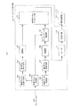
図1は、本実施の形態に係る通信システムの構成例を示す。図1に示す通信システムは、少なくとも、基地局100、及び、複数の端末200(図1では端末#1、端末#2)を有する。基地局100は、各端末200からフィードバックされるCSIを用いて送信ウェイトを算出し、送信ウェイトを用いて、各端末200向けの下りリンク信号を空間多重して送信する。なお、端末200は、サブバンド単位でチャネル推定値(CSI)を基地局100へフィードバックし、基地局100は、サブバンド単位で送信ウェイトを生成、つまり、サブバンド単位で送信ビーム制御を行う。各端末200は、基地局100からMU-MIMO送信される、空間多重された複数のデータ信号を受信する。
[Embodiment 1]
[Outline of communication system]
FIG. 1 shows a configuration example of a communication system according to this embodiment. The communication system shown in FIG. 1 includes at least a
図1に示す通信システムにおいて、基地局100から端末#1向けの下りリンク信号は、端末#2に対する干渉信号となる。同様に、基地局100から端末#2向けの下りリンク信号は、端末#1に対する干渉信号となる。
In the communication system shown in FIG. 1, the downlink signal from
[基地局100の構成]
図2は、本実施の形態に係る基地局100の構成の一例を示すブロック図である。なお、図2には、基地局100の構成要素のうち、本開示の一態様に係る発明に関連する部分が主に示されている。
[Configuration of Base Station 100]
FIG. 2 is a block diagram showing an example of the configuration of
基地局100は、ベースバンド処理部101と、無線送信部113とを含む構成をとる。また、ベースバンド処理部101は、送信ウェイト生成部102と、送信ウェイト情報生成部103と、誤り訂正符号化部104と、変調部105と、送信データ生成部106と、誤り訂正符号化部107と、変調部108と、プリコーディング制御部109と、物理チャネルマッピング部110と、IFFT(Inverse Fast Fourier Transform )部111と、CP(Cyclic Prefix)挿入部112と、を含む。
The
送信ウェイト生成部102は、複数の端末200の各々からフィードバックされるチャネル推定値(CSI)を用いて送信ウェイト(例えば、サブバンド単位の送信ウェイト)を生成する。例えば、送信ウェイトの算出アルゴリズムとしては、チャネル推定値の逆行列を用いるZF(Zero Forcing)法、ZF法に対して雑音電力項を追加したMMSE(Minimum Mean Square Error)法、チャネル推定値を特異値分解して雑音部分空間に対応する固有ベクトルを用いるBD(Block Diagonalization)法などが挙げられる。送信ウェイト生成部101は、生成した送信ウェイトを示す情報(以下、送信ウェイト情報)を、送信ウェイト情報生成部103及びプリコーディング制御部109へ出力する。
Transmission
送信ウェイト情報生成部103は、送信ウェイト生成部101から入力される送信ウェイト情報を含む制御信号を生成する。なお、各端末200向けの送信ウェイト情報には、MU-MIMO送信される他の端末200の送信ウェイトが含まれる。送信ウェイト情報生成部103は、送信ウェイト情報を含む制御信号を誤り訂正符号化部104へ出力する。
Transmission weight
誤り訂正符号化部104は、送信ウェイト情報生成部103から入力される制御信号に対して誤り訂正符号化を行い、符号化後の制御信号を変調部105へ出力する。
Error
変調部105は、誤り訂正符号化部104から入力される制御信号を変調し、変調後の制御信号を物理チャネルマッピング部110へ出力する。
送信データ生成部106は、各端末200向けの送信データ(下りリンクデータ信号)を生成し、生成した送信データを誤り訂正符号化部107へ出力する。
The transmission
誤り訂正符号化部107は、送信データ生成部106から入力される送信データに対して誤り訂正符号化を行い、符号化後の送信データを変調部108へ出力する。
The error
変調部108は、誤り訂正符号化部107から入力される送信データを変調し、変調後の送信データをプリコーディング制御部109へ出力する。
プリコーディング制御部109は、各端末200に対して、送信ウェイト生成部102から入力される送信ウェイトを用いて、変調部108から入力される送信データ、及び、DM-RSをプリコーディングする。プリコーディング制御部109は、プリコーディング後の信号を物理チャネルマッピング部110へ出力する。
The
物理チャネルマッピング部110は、変調部105から入力される制御信号、及び、プリコーディング制御部109から入力される信号を、所定の物理チャネルリソースへマッピングする。また、物理チャネルマッピング部110は、CSI-RSを所定のリソースへマッピングする(図示せず)。物理チャネルマッピング部110は、マッピング後の信号をIFFT部111へ出力する。
The physical
IFFT部111は、物理チャネルマッピング部110から入力される信号に対してIFFT処理を行うことにより、周波数領域信号を時間領域信号に変換する。IFFT部111は、時間領域信号をCP挿入部112へ出力する。
The IFFT
CP挿入部112は、IFFT部111から入力される信号にCPを挿入し、CP挿入後の信号(例えば、OFDM(Orthogonal Frequency Division Multiplexing)信号と呼ぶ)を無線送信部113へ出力する。
無線送信部113は、CP挿入部112から入力される信号に対して、D/A変換、アップコンバート等のRF(Radio Frequency)処理を行い、アンテナを介して各端末200へ無線信号を送信する。このように、基地局100から送信される下りリンク信号は、複数のストリームが空間多重されて送信されている。
The
[端末200の構成]
図3は、本実施の形態に係る端末200の構成の一例を示すブロック図である。なお、図3には、端末200の構成要素のうち、本開示の一態様に係る発明に関連する部分が主に示されている。
[Configuration of Terminal 200]
FIG. 3 is a block diagram showing an example of the configuration of
端末200は、無線受信部201と、ベースバンド処理部202とを含む構成をとる。また、ベースバンド処理部202は、CP除去部203と、FFT(Fast Fourier Transform)部204と、物理チャネルデマッピング部205と、CSI-RSチャネル推定部206と、アップリンク送信処理部207と、送信ウェイト情報取得部208と、ユーザ間干渉電力推定部209と、DM-RSチャネル推定部210と、雑音電力推定部211と、信号分離部212と、復調部213と、誤り訂正復号部214と、を含む。
The terminal 200 has a configuration including a
無線受信部201は、アンテナを介して受信した無線信号に対して、ダウンコンバート、A/D変換等のRF処理を行い、得られる受信信号をCP除去部203へ出力する。
The
CP除去部203は、無線受信部201から入力される受信信号に挿入されているCPを除去し、CP除去後の信号をFFT部204へ出力する。
FFT部204は、CP除去部203から入力される信号に対してFFT処理を行うことにより、時間領域信号を周波数領域信号に変換する。FFT部204は、周波数領域信号を物理チャネルデマッピング部205へ出力する。
The
物理チャネルデマッピング部205は、FFT部204から入力される信号から、下りリンクデータ信号、制御信号(送信ウェイト情報を含む)、CSI-RS、及び、DM-RSをそれぞれ抽出する。物理チャネルデマッピング部205は、下りリンクデータ信号を信号分離部212へ出力し、制御信号を送信ウェイト情報取得部208へ出力し、CSI-RSをCSI-RSチャネル推定部206へ出力し、DM-RSをDM-RSチャネル推定部210へ出力する。
The physical
CSI-RSチャネル推定部206は、物理チャネルデマッピング部205から入力されるCSI-RSを用いてチャネル推定値(CSI又はCSIチャネル推定値と呼ぶ)を算出する。CSI-RSチャネル推定部206は、CSIチャネル推定値をアップリンク送信処理部207及びユーザ間干渉電力推定部209へ出力する。
The CSI-RS
アップリンク送信処理部207は、CSI-RSチャネル推定部206から入力されるCSIチャネル推定値に対して送信処理を行い、送信処理後のCSIチャネル推定値を基地局100へフィードバックする。
The uplink
送信ウェイト情報取得部208は、物理チャネルデマッピング部205から入力される制御信号から送信ウェイト情報を取得する。そして、送信ウェイト情報取得部208は、取得した送信ウェイト情報をユーザ間干渉電力推定部209へ出力する。
The transmission weight
ユーザ間干渉電力推定部209は、CSI-RSチャネル推定部206から入力されるCSIチャネル推定値、及び、送信ウェイト情報取得部208から入力される、MU-MIMO送信される他の端末200の送信ウェイトを用いて、他の端末向けの信号が自機向けの信号に与える干渉電力(つまり、ユーザ間干渉電力)を推定する。なお、ユーザ間干渉電力推定部209は、後述する軟判定ウェイトの生成時に用いるユーザ間干渉電力を推定する際、後述する信号分離部212で生成される受信ウェイトを用いる。ユーザ間干渉電力推定部209は、推定したユーザ間干渉電力を信号分離部212及び復調部213へ出力する。
The inter-user interference
DM-RSチャネル推定部210は、物理チャネルデマッピング部205から入力されるDM-RSを用いてチャネル推定値(以下、DM-RSチャネル推定値と呼ぶ)を算出する。そして、DM-RSチャネル推定部210は、DM-RSチャネル推定値を、雑音電力推定部211、信号分離部212及び復調部213へ出力する。
DM-RS
雑音電力推定部211は、DM-RSチャネル推定部210から入力されるDM-RSチャネル推定値を用いて雑音電力を推定し、推定した雑音電力を信号分離部212及び復調部213へ出力する。
The noise
信号分離部212は、ユーザ間干渉電力推定部209から入力されるユーザ間干渉電力、DM-RSチャネル推定部210から入力されるDM-RSチャネル推定値、及び、雑音電力推定部211から入力される雑音電力を用いて、物理チャネルデマッピング部205から入力される受信信号(下りリンクデータ信号)を複数の信号(ストリーム)に分離する。具体的には、信号分離部212は、ユーザ間干渉電力、DM-RSチャネル推定値及び雑音電力を用いて受信ウェイト(例えば、MMSE受信ウェイト)を生成する。そして、信号分離部212は、受信ウェイトを受信信号に乗算することにより、信号を分離する。信号分離部212は、分離した信号及び受信ウェイトを復調部213へ出力し、受信ウェイトをユーザ間干渉電力推定部209へ出力する。
The
復調部213は、信号分離部212から入力される受信ウェイト、ユーザ間干渉電力推定部209から入力されるユーザ干渉電力、DM-RSチャネル推定部210から入力されるDM-RSチャネル推定値、及び、雑音電力推定部211から入力される雑音電力を用いて、復調・軟判定処理を行う。
The
具体的には、復調部213は、信号分離部212から入力される信号を復調し軟判定値(尤度系列)を算出する。また、復調部213は、受信ウェイト、DM-RSチャネル推定値、ユーザ間干渉電力及び雑音電力を用いて軟判定ウェイト(例えば、SINR(Signal to Interference and Noise Ratio))を生成する。そして、復調部213は、軟判定ウェイトを軟判定値に乗算することにより重みづけを行う。例えば、軟判定ウェイトは、ユーザ間干渉が小さいほど大きい値を採り、ユーザ間干渉が大きいほど小さい値を採る。復調部213は、重みづけ後の軟判定値を誤り訂正復号部214へ出力する。
Specifically, the
誤り訂正復号部214は、復調部213から入力される重みづけ後の軟判定値に対して誤り訂正復号を行い、復号後の信号(つまり、希望信号の復号データ)を出力する。
The error
[基地局100及び端末200の動作]
次に、上述した基地局100及び端末200の動作について説明する。
[Operations of
Next, operations of the
<受信ウェイト及び軟判定ウェイトの生成方法>
まず、端末200の信号分離部212及び復調部213において生成される受信ウェイト及び軟判定ウェイトの生成方法について詳細に説明する。
<Method of generating reception weight and soft decision weight>
First, a method of generating a reception weight and a soft decision weight generated by the
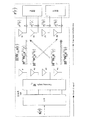
以下では、一例として、図4に示すように、基地局100が4本の送信アンテナ#1〜#4を有し、各端末200(端末#1、端末#2)が2本の受信アンテナ#1、#2をそれぞれ有し、4Tx×2Rx×2UEのMU-MIMOによる空間多重を行う場合について説明する。なお、基地局100と複数の端末200との間のMU-MIMO空間多重において使用する送受信アンテナ数はこれに限定されるものではない。
In the following, as an example, as shown in FIG. 4, the
まず、一般的な受信ウェイト及び軟判定ウェイトの生成例について説明する。なお、受信ウェイト及び軟判定ウェイトは、実際には、サブキャリア及びOFDMシンボル単位(つまり、リソースエレメント(RE:Resource Element)単位)で定義されるが、ここでは、説明を簡易化するために省略する。 First, an example of generating general reception weights and soft decision weights will be described. Note that the reception weight and the soft decision weight are actually defined in units of subcarriers and OFDM symbols (that is, resource element (RE: Resource Element) units), but are omitted here for simplification of description. To do.
ユーザ間干渉が無い場合、各端末が基地局から受信する受信信号r(図4の実線矢印に相当)を次式(1)で定義する。

ここで、H(1),H(2)は基地局と各端末#1,#2との間の伝搬路を表すチャネル応答を示し、WTX (1),WTX (2)は各端末#1,#2向けの送信ウェイトを示し、s(1),s(2)は各端末#1,#2向けの送信信号(希望信号)を示し、n(1),n(2)は各端末#1,#2での雑音を示し、各々、次式(2)〜(5)で表される。
以下では、式(1)においてチャネル応答H'=HWTXと表すこともある。H'は、送信ウェイトWTXが適用されたDM-RSによって推定されるDM-RSチャネル推定値である。以降、H、H’は推定値として説明する。 In the following, the channel response H′=HW TX may be expressed in equation (1). H′ is a DM-RS channel estimation value estimated by the DM-RS to which the transmission weight W TX is applied. Hereinafter, H and H'will be described as estimated values.
例えば、端末#1の受信ウェイト(MMSE受信ウェイト)WRX (1)は次式(6)で表される。
ここで、上添字Hはエルミート転置演算を示し、Pnは雑音電力(例えば、サブフレーム内の平均値)を示し、INRXは端末の受信アンテナ数サイズの単位行列を示す。なお、端末#2の受信ウェイトについても式(6)と同様に算出される。
Here, the superscript H indicates the Hermitian transposition operation, P n indicates the noise power (for example, the average value in the subframe), and I NRX indicates the unit matrix of the number of receiving antennas of the terminal. Note that the reception weight of
端末#1は、受信ウェイトWRX (1)を受信信号r(式(1)の端末#1に対応する部分)に乗算して、次式(7)のように2ストリームの信号に分離する。
なお、式(7)において、WRX (1)H'(1)とwh'との関係は、次式(8)で定義される。
また、式(7)に示す2つのストリームの各々に対する軟判定ウェイト(SINR)は次式(9)で表される。
式(9)では、|s1|2=|s2|2=1とし、|n1|2=|n2|2=Pnとしている。 In Expression (9), |s 1 | 2 =|s 2 | 2 =1 and |n 1 | 2 =|n 2 | 2 =P n .
ここで、式(9)に示す軟判定ウェイトSINR1 (1)及びSINR2 (1)の各々において、|wh'11 (1)|2及び|wh'22 (1)|2は希望信号電力を表し、(|w11 (1)|2+|w12 (1)|2)Pn (1)及び(|w21 (1)|2+|w22 (1)|2)Pn (1)は雑音電力を表し、|wh'12 (1)|2及び|wh'21 (1)|2は同一端末内での2つのストリーム間の干渉電力を表す。 Here, in each of the soft decision weights SINR 1 (1) and SINR 2 (1) shown in equation (9), |wh' 11 (1) | 2 and |wh' 22 (1) | 2 are the desired signal powers. , (|w 11 (1) | 2 +|w 12 (1) | 2 )P n (1) and (|w 21 (1) | 2 +|w 22 (1) | 2 )P n ( 1) represents noise power, and |wh' 12 (1) | 2 and |wh' 21 (1) | 2 represent interference power between two streams in the same terminal.
なお、端末#2において受信される2つのストリームについても式(9)と同様に軟判定ウェイト(SINR)が算出される。
It should be noted that soft decision weights (SINR) are calculated for the two streams received at
次に、本実施の形態における受信ウェイト及び軟判定ウェイトの生成例について説明する。 Next, a generation example of the reception weight and the soft decision weight according to the present embodiment will be described.
本実施の形態では、端末200は、上述した一般的な受信ウェイト及び軟判定ウェイトの生成に用いるパラメータに加え、他の端末向けの信号によるユーザ間干渉電力を考慮して受信ウェイト及び軟判定ウェイトを生成する。 In the present embodiment, terminal 200 considers the inter-user interference power due to signals for other terminals, in addition to the parameters used to generate the general reception weights and soft decision weights described above, To generate.
具体的には、ユーザ間干渉を考慮した場合、各端末200が基地局100から受信する受信信号r(図4の実線矢印及び点線矢印に相当)を次式(10)で定義する。
式(10)(図4を参照)において、H(1)WTX (2)s(2)は、端末#2から端末#1へのユーザ間干渉を表し、H(2)WTX (1)s(1)は、端末#1から端末#2へのユーザ間干渉を表す。
In Expression (10) (see FIG. 4 ), H (1) W TX (2) s (2) represents the inter-user interference from
この場合、端末#1の信号分離部212で使用される、第k番目のサブキャリア及び第l番目のOFDMシンボルにおける受信ウェイトWRX (1)(k,l)は次式(11)で表される。
式(11)において、H(1)(k,l)WTX (1)(k,l)は、DM-RSチャネル推定部210で推定されるDM-RSチャネル推定値を表し、Pn (1)は雑音電力推定部211で推定される雑音電力を表す。また、式(11)において、Pi (1)(k,l)は、ユーザ間干渉電力推定部209で推定されるユーザ間干渉電力(つまり、端末#2の信号から端末#1の信号が受ける干渉電力)であり、次式(12)、式(13)で表される。
式(13)において、関数diag()は対角行列を表す。また、式(13)において、H(1)(k,l)はCSI-RSチャネル推定部206で推定されるチャネル推定値(CSI)を表し、WTX (2)(k,l)は、送信ウェイト情報取得部208において基地局100から取得する、端末#1に対して干渉を与える端末(以下、与干渉端末と呼ぶ。ここでは端末#2)の送信ウェイトを表す。
In Expression (13), the function diag() represents a diagonal matrix. Further, in Expression (13), H (1) (k,l) represents a channel estimation value (CSI) estimated by the CSI-RS
各端末200において、DM-RSチャネル推定値(H(1)(k,l)WTX (1)(k,l))及びユーザ間干渉電力Piは、サブキャリア及びOFDMシンボル単位(つまり、リソースエレメント単位)で推定される。つまり、端末200は、サブキャリア及びOFDMシンボル単位でユーザ間干渉電力を推定し、ユーザ間干渉電力を用いて受信ウェイトWRX (1)(k,l)をサブキャリア及びOFDMシンボル単位で生成する。なお、雑音電力Pnは例えば、所定のサブキャリア及びOFDMシンボルの平均値でもよい。 In each terminal 200, the DM-RS channel estimation value (H (1) (k,l)W TX (1) (k,l)) and the inter-user interference power P i are subcarrier and OFDM symbol units (that is, It is estimated in units of resource elements. That is, terminal 200 estimates inter-user interference power in subcarrier and OFDM symbol units, and generates reception weight W RX (1) (k,l) in subcarrier and OFDM symbol units using inter-user interference power. .. Note that the noise power P n may be, for example, an average value of predetermined subcarriers and OFDM symbols.
端末#1の信号分離部212は、式(11)に示す受信ウェイトWRX (1)(k,l)を受信信号r(式(1)の端末#1に対応する部分)に乗算して2ストリームの信号に分離する。
The
式(11)より、ユーザ間干渉電力Piが小さいほどZF(Zero Forcing)法と同様の特性に近似し、ユーザ間干渉電力Piが大きいほどMRC(Maximum Ratio Combining:最大比合成)法と同様の特性に近似すると云える。 From Equation (11), the smaller the inter-user interference power P i is, the more similar the characteristics to the ZF (Zero Forcing) method are, and the larger the inter-user interference power P i is the MRC (Maximum Ratio Combining) method. It can be said that they have similar characteristics.
また、式(11)に示す受信ウェイトWRX (1)(k,l)を用いて分離された2つのストリームの各々に対する軟判定ウェイト(SINR)は次式(14)で表される。
式(14)において、P'i1 (1)(k,l)及びP'i2 (1)(k,l)は、ユーザ間干渉電力推定部209において推定されるユーザ間干渉電力(つまり、端末#2の信号から端末#1の信号が受ける干渉電力)であり、次式(15)で表される。なお、軟判定ウェイトの生成に用いられるP'Iは、受信ウェイトWRX (1)(k,l)が考慮されている点で、受信ウェイトWRX (1)(k,l)の生成に用いられるユーザ間干渉電力Pi(式(12)及び式(13))と異なる。
式(15)より、ユーザ間干渉電力P'iが小さいほど軟判定ウェイトは大きくなり、ユーザ間干渉電力P'iが大きいほど軟判定ウェイトは小さくなる。すなわち、ユーザ間干渉電力P'Iが小さいほど、端末200で受信した基地局100からの希望信号の確からしさ(つまり、軟判定結果である尤度)は高くなる。 From equation (15), inter-user interference power P 'smaller the i soft decision weights increased, inter-user interference power P' greater the i soft decision weights smaller. That is, the smaller the inter-user interference power P′ I, the higher the certainty of the desired signal received by the terminal 200 from the base station 100 (that is, the likelihood of a soft decision result).
<干渉抑圧処理の動作例>
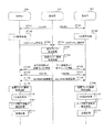
図5は、図1に示す通信システムの各装置における動作を示すシーケンス図である。
<Operation example of interference suppression processing>
FIG. 5 is a sequence diagram showing an operation in each device of the communication system shown in FIG.
図5において、ステップ(以下、単に「ST」と表す)101では、基地局100は、各端末200(端末#1、#2)に対してCSI-RSを送信する。
In step (hereinafter, simply referred to as “ST”) 101 in FIG. 5,
ST102では、各端末200のCSI-RSチャネル推定部206は、ST101で受信したCSI-RSを用いてCSIチャネル推定値を算出する。ST103では、各端末200のアップリンク送信処理部207は、算出したCSIチャネル推定値を基地局100へフィードバックする。
In ST102, CSI-RS
ST104では、基地局100の送信ウェイト生成部102は、各端末200からフィードバックされたCSIチャネル推定値を用いて送信ウェイトを生成する。ここで、CSIチャネル推定値は、例えば、サブバンド単位でフィードバックされ、送信ウェイトもサブバンド単位で生成される。
In ST104, transmission
ST105では、基地局100の送信ウェイト情報生成部103は、ST104で生成した送信ウェイトを示す送信ウェイト情報を生成する。具体的には、基地局100は、端末#1に対して、与干渉端末である端末#2の送信ウェイトを示す送信ウェイト情報を生成し、端末#2に対して、与干渉端末である端末#1の送信ウェイトを示す送信ウェイト情報を生成する。
In ST105, transmission weight
ST106では、基地局100は、ST105で生成した送信ウェイト情報を各端末200へ送信する。具体的には、基地局100は、端末#2の送信ウェイトを示す送信ウェイト情報を端末#1へ送信し、端末#1の送信ウェイトを示す送信ウェイト情報を端末#2へ送信する。
In ST106,
ST107では、基地局100は、各端末200(端末#1、#2)に対してCSI-RSを送信する。ST108では、基地局100は、各端末200(端末#1、#2)に対して下りリンク信号(下りリンクデータ信号及びDM-RSなどを含む。MU-MIMO送信信号と呼ぶこともある)を送信する。
In ST107,
ST109では、各端末200の送信ウェイト情報取得部208は、ST106で送信される送信ウェイト情報から与干渉端末向けの送信ウェイトを取得する。ST110では、各端末200のCSI-RSチャネル推定部206は、ST107で送信されるCSI-RS(つまり、ビームフォーミング制御が行われるタイミングで受信したCSI-RS)を用いてCSIチャネル推定値を算出する。
In ST109, transmission weight
ST111では、各端末200のユーザ間干渉電力推定部209は、ST109で取得した与干渉端末の送信ウェイトと、ST110で推定したCSIチャネル推定値とを用いて、ユーザ間干渉電力を推定する(例えば、式(12)、式(13)、式(15)を参照)。
In ST111, inter-user interference
ST112では、各端末200は、ST111で推定したユーザ間干渉電力を用いて、ST108で受信した下りリンクデータ信号に対する受信処理を行う。具体的には、各端末200の信号分離部212は、ユーザ間干渉電力(例えば、式(12)、式(13)を参照)を用いて受信ウェイトを生成し(例えば、式(11)を参照)、受信ウェイトを受信信号に乗算して信号分離を行う。また、各端末200の復調部213は、ユーザ間干渉電力(例えば、式(15)を参照)を用いて軟判定ウェイトを生成し(例えば、式(14)を参照)、軟判定ウェイトを用いて、軟判定値に対する重みづけを行う。
In ST112, each terminal 200 performs reception processing on the downlink data signal received in ST108, using the inter-user interference power estimated in ST111. Specifically, the
このように、端末200は、サブキャリア及びOFDMシンボル毎のユーザ干渉電力を考慮した受信ウェイト及び軟判定ウェイトを用いて希望信号の受信処理を行うことで、ユーザ間干渉を抑圧して、希望信号の受信品質を向上させることができる。 In this way, terminal 200 suppresses inter-user interference and performs desired signal reception processing by performing reception processing of a desired signal using a reception weight and a soft decision weight considering user interference power for each subcarrier and OFDM symbol. The reception quality of can be improved.
[効果の説明]
以上のように、本実施の形態では、端末200において、無線受信部201は、基地局100からMU-MIMO送信される、空間多重された複数のデータ信号を受信し、ユーザ間干渉電力推定部209は、MU-MIMO送信される他の端末200の送信ウェイトを用いてユーザ間干渉電力を推定し、信号分離部212は、ユーザ間干渉電力を用いて受信ウェイトを生成し、受信ウェイトを用いて複数のデータ信号を分離する。また、復調部213は、分離された複数のデータ信号をそれぞれ復調し軟判定値を算出し、ユーザ間干渉電力及び受信ウェイトを用いて軟判定ウェイトを生成し、軟判定ウェイトを用いて、軟判定値に対する重みづけを行う。
[Explanation of effect]
As described above, in the present embodiment, in
これにより、端末200では、サブキャリア毎に推定されるユーザ間干渉を考慮して受信処理(信号分離及び軟判定値に対する重みづけ処理)を行うことができる。よって、マルチパス環境のように周波数変動が激しい場合でも、端末200は、実際の周波数特性に応じた適切な受信ウェイト及び軟判定ウェイトを用いて受信処理を行うことができるので、受信性能(信号分離性能及び復号性能)を向上させることができる。よって、本実施の形態によれば、端末200においてユーザ間干渉を効果的に抑圧することができる。
By this means, terminal 200 can perform reception processing (signal separation and weighting processing for soft decision values) in consideration of inter-user interference estimated for each subcarrier. Therefore, even when frequency fluctuations are severe like in a multipath environment, terminal 200 can perform reception processing using appropriate reception weights and soft decision weights according to actual frequency characteristics. Separation performance and decoding performance) can be improved. Therefore, according to the present embodiment, inter-user interference can be effectively suppressed in
また、本実施の形態では、CSIチャネル推定値がサブキャリア単位よりも粗い粒度(例えばサブバンド単位)でフィードバックされ、基地局100において使用される送信ウェイトの制御粒度もサブキャリア単位よりも粗い。すなわち、MU-MIMO送信において、受信ウェイトはサブキャリア毎に生成されるのに対して、送信ウェイトは複数のサブキャリア単位(例えば、サブバンド単位)で生成される。これにより、本実施の形態に係る通信システムでは、送信側(基地局100)において送信ウェイト制御の演算量の増加を抑えることができる。
Further, in the present embodiment, the CSI channel estimation value is fed back at a granularity (for example, subband unit) that is coarser than the subcarrier unit, and the control granularity of the transmission weight used in
以上より、本実施の形態によれば、演算量の増加を抑えて、ユーザ間干渉を抑圧することができる。 As described above, according to the present embodiment, it is possible to suppress an increase in the amount of calculation and suppress inter-user interference.
なお、本実施の形態において、基地局100から端末200へ通知される与干渉端末の送信ウェイトの通知方法は、特に限定されない。例えば、基地局100は、送信ウェイトそのものを示す情報を端末200へ通知してもよい。または、基地局100は、送信ウェイトをコードブック化し、生成した送信ウェイトに対応するコードブックを端末200へ通知してもよい。
In addition, in the present embodiment, the method of notifying the transmission weight of the interfering terminal notified from
また、本実施の形態において、CSIチャネル推定値のフィードバック粒度及び送信ウェイトの制御粒度としてサブバンド単位を例に挙げて説明したが、上記粒度はサブバンド単位に限定されない。 Further, although a case has been described with the present embodiment as an example where the feedback granularity of the CSI channel estimation value and the control granularity of the transmission weight are subband units, the granularity is not limited to subband units.
また、図5では2台の端末200に対するMU-MIMO処理について説明したが、MU-MIMOの対象となる端末200の数は2台に限定されない。
Further, although the MU-MIMO process for two
[実施の形態2]
実施の形態1では、ユーザ間干渉電力の推定に用いる与干渉端末の送信ウェイトを基地局から端末へ通知する場合について説明した。これに対して、本実施の形態では、与干渉端末の送信ウェイトを端末が推定する場合について説明する。
[Second Embodiment]
つまり、本実施の形態に係る基地局100a(図示しない)は、与干渉端末の送信ウェイトを各端末に通知しない。よって、本実施の形態に係る基地局100aは、実施の形態1に係る基地局100(図2)における送信ウェイト情報の送信処理に関する構成部(送信ウェイト情報生成部103、誤り訂正符号化部104、変調部105)を備えない。
That is,
図6は、本実施の形態に係る端末300の構成の一例を示すブロック図である。なお、図6には、端末300の構成要素のうち、本開示の一態様に係る発明に関連する部分が主に示されている。
FIG. 6 is a block diagram showing an example of the configuration of
また、図6において、実施の形態1(図3)と同様の処理を行う構成部には同一の符号を付し、その説明を省略する。具体的には、端末300は、実施の形態1に係る端末200と比較して、送信ウェイト情報取得部208の代わりに、送信ウェイト生成部301及び送信ウェイト保持部302を備える点が異なる。
Further, in FIG. 6, the same components as those in Embodiment 1 (FIG. 3) are designated by the same reference numerals, and the description thereof will be omitted. Specifically, terminal 300 is different from terminal 200 according to
送信ウェイト生成部301は、CSI-RSチャネル推定部206から入力されるCSIチャネル推定値を用いて、与干渉端末の送信ウェイトを生成する。
Transmission
ただし、端末300は、以下の条件の場合に与干渉端末の送信ウェイトを生成する。
条件1:送信ウェイト生成アルゴリズムとしてBD(Block Diagonalization)法を使用
条件2:MU-MIMO送信における端末数が2個
However, terminal 300 generates the transmission weight of the interfering terminal under the following conditions.
Condition 1: The BD (Block Diagonalization) method is used as the transmission weight generation algorithm Condition 2: The number of terminals in MU-MIMO transmission is 2
BD法では、与干渉端末の送信ウェイトは、ユーザ間干渉を受ける端末(以下、被干渉端末と呼ぶ)のチャネル推定値(つまり、端末300のCSI-RSチャネル推定部206で推定されるCSIチャネル推定値)から算出される。
In the BD method, the transmission weight of an interfering terminal is a channel estimation value of a terminal (hereinafter referred to as an interfered terminal) that is subject to inter-user interference (that is, a CSI channel estimated by CSI-RS
具体的には、BD法では、与干渉端末の送信ウェイトを算出する場合、被干渉端末のチャネル推定値を特異値分解し、雑音部分空間に対応する固有ベクトルを与干渉端末の送信ウェイトとして用いる。 Specifically, in the BD method, when calculating the transmission weight of an interfering terminal, the channel estimation value of the interfered terminal is decomposed into singular values and the eigenvector corresponding to the noise subspace is used as the transmission weight of the interfering terminal.
これにより、端末300の送信ウェイト生成部301は、基地局100aから与干渉端末の送信ウェイトを通知されなくても、自機のチャネル推定値(CSIチャネル推定値)を用いて、与干渉端末の送信ウェイトを生成することができる。
By this means, transmission
送信ウェイト生成部301は、生成した与干渉端末の送信ウェイトを送信ウェイト保持部302へ出力する。
The transmission
送信ウェイト保持部302は、送信ウェイト生成部301から入力される与干渉端末の送信ウェイトを保持する。そして、送信ウェイト保持部302は、保持している与干渉端末の送信ウェイトをユーザ間干渉電力推定部209へ出力する。
The transmission
なお、送信ウェイト生成部301において与干渉端末の送信ウェイトの生成に使用されるCSIチャネル推定値は、基地局100aへフィードバックされ、送信ウェイトの生成にも使用される。送信ウェイト保持部302は、基地局100aへフィードバックされたCSIチャネル推定値から算出される送信ウェイトによって送信ビーム制御された下りリンクデータの受信タイミングにおいて、当該CSIチャネル推定値によって生成された与干渉端末の送信ウェイトを出力する。これにより、ユーザ間干渉電力推定部209は、基地局100aから送信された下りリンクデータ信号に対する送信ビーム制御で使用されたCSIチャネル推定値と同様のCSIチャネル推定値を用いて生成された与干渉端末の送信ウェイトを用いてユーザ間干渉電力を推定することができる。
The CSI channel estimation value used in transmission
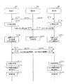
図7は、本実施の形態に係る通信システムの各装置における動作を示すシーケンス図である。なお、図7において、実施の形態1(図5)と同様の処理には同一の符号を付し、その説明を省略する。 FIG. 7 is a sequence diagram showing an operation in each device of the communication system according to the present embodiment. In FIG. 7, the same processes as those in Embodiment 1 (FIG. 5) are designated by the same reference numerals, and the description thereof will be omitted.
図7において、基地局100aは、実施の形態1に係る基地局100と異なり、送信ウェイト情報の生成及び送信処理(図5に示すST105、ST106)を行わない。
7, unlike
一方、各端末300(端末#1,端末#2)は、ST201において、与干渉端末の送信ウェイトを生成する。具体的には、端末#1の送信ウェイト生成部301は、ST102で推定したCSIチャネル推定値を用いて、与干渉端末である端末#2の送信ウェイトを生成する。同様に、端末#2の送信ウェイト生成部301は、ST102で推定したCSIチャネル推定値を用いて、与干渉端末である端末#1の送信ウェイトを生成する。
On the other hand, each terminal 300 (
そして、各端末300のユーザ間干渉電力推定部209は、ST201で生成した与干渉端末の送信ウェイトを用いてユーザ間干渉電力を推定する。
Then, inter-user interference
このようにして、本実施の形態では、端末300は、自機のCSIチャネル推定値を用いて、与干渉端末の送信ウェイトを生成する。これにより、本実施の形態では、実施の形態1の効果に加え、ユーザ間干渉電力の推定に使用する与干渉端末の送信ウェイトの通知に要するシグナリングを削減することができる。 In this way, according to the present embodiment, terminal 300 generates a transmission weight of the interfering terminal using the CSI channel estimation value of the terminal itself. By this means, in this embodiment, in addition to the effects of the first embodiment, it is possible to reduce the signaling required for notifying the transmission weight of the interfering terminal used for estimating the inter-user interference power.
以上、本開示の一態様に係る各実施の形態について説明した。 In the above, each embodiment concerning one mode of this indication was explained.
なお、上記実施の形態1と実施の形態2とを適宜組み合わせて実施してもよい。すなわち、各端末(端末200,300)において、基地局100から与干渉端末の送信ウェイトを受信してもよく、各端末で与干渉端末の送信ウェイトを生成してもよい。
The first embodiment and the second embodiment may be appropriately combined and implemented. That is, each terminal (
上記実施の形態では、端末200,300においてCSI-RSを用いてチャネル推定する場合について説明したが、チャネルを推定できる参照信号であればよい。例えば、CRS(Cell-specific Reference Signal)を用いてもよい。
In the above embodiment, a case has been described where
また、上記実施の形態では、端末200,300が、ユーザ間干渉電力を用いて受信ウェイト及び軟判定ウェイトの双方を生成する場合について説明したが、これに限定されず、例えば、端末200,300は、ユーザ間干渉電力を用いて、受信ウェイト又は軟判定ウェイトの何れか一方を生成してもよい。
Further, although cases have been described with the above embodiments where
また、上記実施の形態では、本開示の一態様をハードウェアで構成する場合を例にとって説明したが、本開示はハードウェアとの連携においてソフトウェアで実現することも可能である。 Further, although cases have been described with the above embodiment as examples where an aspect of the present disclosure is configured by hardware, the present disclosure can also be implemented by software in cooperation with hardware.
また、上記実施の形態の説明に用いた各機能ブロックは、典型的には、入力端子および出力端子を有する集積回路であるLSIとして実現される。集積回路は、上記実施の形態の説明に用いた各機能ブロックを制御し、入力端子と出力端子を備えてもよい。これらは個別に1チップ化されてもよいし、一部または全てを含むように1チップ化されてもよい。ここでは、LSIとしたが、集積度の違いにより、IC、システムLSI、スーパーLSI、ウルトラLSIと呼称されることもある。 Each functional block used in the description of the above embodiments is typically realized as an LSI which is an integrated circuit having an input terminal and an output terminal. The integrated circuit may control each of the functional blocks used in the description of the above embodiments, and may include an input terminal and an output terminal. These may be individually made into one chip, or may be made into one chip so as to include some or all of them. The name used here is LSI, but it may also be called IC, system LSI, super LSI, or ultra LSI depending on the degree of integration.
また、集積回路化の手法はLSIに限るものではなく、専用回路または汎用プロセッサで実現してもよい。LSI製造後に、プログラムすることが可能なFPGA(Field Programmable Gate Array)や、LSI内部の回路セルの接続や設定を再構成可能なリコンフィギュラブル・プロセッサを利用してもよい。 Further, the method of circuit integration is not limited to LSI, and it may be realized by a dedicated circuit or a general-purpose processor. A field programmable gate array (FPGA) that can be programmed after the LSI is manufactured, or a reconfigurable processor capable of reconfiguring the connection and setting of circuit cells inside the LSI may be used.
さらには、半導体技術の進歩または派生する別技術によりLSIに置き換わる集積回路化の技術が登場すれば、当然、その技術を用いて機能ブロックの集積化を行ってもよい。バイオ技術の適用等が可能性としてありえる。 Furthermore, if integrated circuit technology comes out to replace LSI's as a result of the advancement of semiconductor technology or a derivative other technology, it is naturally also possible to carry out function block integration using this technology. The application of biotechnology is possible.
本開示の一態様に係る発明は、無線通信システムに好適である。 The invention according to one aspect of the present disclosure is suitable for a wireless communication system.
100,100a 基地局
101,202 ベースバンド処理部
102,301 送信ウェイト生成部
103 送信ウェイト情報生成部
104,107 誤り訂正符号化部
105,108 変調部
106 送信データ生成部
109 プリコーディング制御部
110 物理チャネルマッピング部
111 IFFT部
112 CP挿入部
113 無線送信部
200,300 端末
201 無線受信部
203 CP除去部
204 FFT部
205 物理チャネルデマッピング部
206 CSI-RSチャネル推定部
207 アップリンク送信処理部
208 送信ウェイト情報取得部
209 ユーザ間干渉電力推定部
210 DM-RSチャネル推定部
211 雑音電力推定部
212 信号分離部
213 復調部
214 誤り訂正復号部
302 送信ウェイト保持部
100, 100a Base station 101, 202
Claims (8)
前記MU-MIMO送信される他の端末の送信ウェイトを用いてユーザ間干渉電力を推定する推定部と、
前記ユーザ間干渉電力を用いて受信ウェイトを生成し、前記受信ウェイトを用いて前記複数のデータ信号を分離する信号分離部と、
を具備する端末。 A receiving unit that receives a plurality of spatially multiplexed data signals transmitted from a base station by MU-MIMO (Multi User-Multiple Input Multiple Output),
An estimation unit that estimates the inter-user interference power using the transmission weights of the other terminals that are MU-MIMO transmitted,
A signal demultiplexing unit that generates a reception weight using the inter-user interference power and separates the plurality of data signals using the reception weight,
A terminal equipped with.
請求項1に記載の端末。 A soft decision value is calculated by demodulating each of the separated data signals, a soft decision weight is generated using the inter-user interference power and the reception weight, and the soft decision weight is used to generate the soft decision value. Further comprising a demodulation unit for weighting
The terminal according to claim 1.
前記信号分離部は、前記受信ウェイトをサブキャリア毎に生成する、
請求項1に記載の端末。 The estimation unit estimates the inter-user interference power for each subcarrier,
The signal separation unit generates the reception weight for each subcarrier,
The terminal according to claim 1.
請求項2に記載の端末。 The demodulation unit generates the soft decision weight for each subcarrier,
The terminal according to claim 2.
請求項1に記載の端末。 Further comprising an acquisition unit that acquires a control signal including information about the transmission weight of the other terminal from the base station,
The terminal according to claim 1.
請求項1に記載の端末。 Further comprising a generation unit that generates a transmission weight of the other terminal using the channel estimation values of the base station and the own device.
The terminal according to claim 1.
前記MU-MIMO送信される他の端末の送信ウェイトを用いてユーザ間干渉電力を推定し、
前記ユーザ間干渉電力を用いて受信ウェイトを生成し、前記受信ウェイトを用いて前記複数のデータ信号を分離する、
通信方法。 Receives multiple spatially multiplexed data signals transmitted from the base station by MU-MIMO (Multi User-Multiple Input Multiple Output),
Estimate the inter-user interference power using the transmission weight of the other terminal to be transmitted MU-MIMO,
A reception weight is generated using the inter-user interference power, and the plurality of data signals are separated using the reception weight.
Communication method.
請求項7に記載の通信方法。 A soft decision value is calculated by demodulating each of the separated data signals, a soft decision weight is generated using the inter-user interference power and the reception weight, and the soft decision weight is used to generate the soft decision value. Weighting,
The communication method according to claim 7.
Priority Applications (3)
| Application Number | Priority Date | Filing Date | Title |
|---|---|---|---|
| JP2016204504A JP6719085B2 (en) | 2016-10-18 | 2016-10-18 | Terminal and communication method |
| PCT/JP2016/005162 WO2018073851A1 (en) | 2016-10-18 | 2016-12-16 | Terminal and communication method |
| US16/366,569 US10749558B2 (en) | 2016-10-18 | 2019-03-27 | Terminal and communication method in a multi user-multiple input multiple output (MU-MIMO) scheme |
Applications Claiming Priority (1)
| Application Number | Priority Date | Filing Date | Title |
|---|---|---|---|
| JP2016204504A JP6719085B2 (en) | 2016-10-18 | 2016-10-18 | Terminal and communication method |
Publications (2)
| Publication Number | Publication Date |
|---|---|
| JP2018067774A JP2018067774A (en) | 2018-04-26 |
| JP6719085B2 true JP6719085B2 (en) | 2020-07-08 |
Family
ID=62019099
Family Applications (1)
| Application Number | Title | Priority Date | Filing Date |
|---|---|---|---|
| JP2016204504A Expired - Fee Related JP6719085B2 (en) | 2016-10-18 | 2016-10-18 | Terminal and communication method |
Country Status (3)
| Country | Link |
|---|---|
| US (1) | US10749558B2 (en) |
| JP (1) | JP6719085B2 (en) |
| WO (1) | WO2018073851A1 (en) |
Families Citing this family (6)
| Publication number | Priority date | Publication date | Assignee | Title |
|---|---|---|---|---|
| US10772104B2 (en) * | 2017-12-21 | 2020-09-08 | Samsung Electronics Co., Ltd. | Wireless communication device and symbol-based processing method for downlink signals thereof |
| JP7196687B2 (en) * | 2019-02-26 | 2022-12-27 | 日本電信電話株式会社 | Wireless communication system, wireless communication method, transmitting station device and receiving station device |
| JP7196686B2 (en) * | 2019-02-26 | 2022-12-27 | 日本電信電話株式会社 | Wireless communication system, wireless communication method, transmitting station device and receiving station device |
| WO2021029067A1 (en) * | 2019-08-15 | 2021-02-18 | 株式会社Nttドコモ | Terminal and communication method |
| JP7264251B2 (en) * | 2019-08-20 | 2023-04-25 | 日本電信電話株式会社 | Wireless communication system, wireless communication method and receiving station device |
| WO2021044625A1 (en) * | 2019-09-06 | 2021-03-11 | 日本電信電話株式会社 | Wireless communication system, wireless communication method, transmission station device, and reception station device |
Family Cites Families (9)
| Publication number | Priority date | Publication date | Assignee | Title |
|---|---|---|---|---|
| JP3563421B2 (en) | 1993-08-25 | 2004-09-08 | 株式会社東芝 | Wireless communication device |
| JP4663369B2 (en) * | 2004-05-20 | 2011-04-06 | パナソニック株式会社 | Wireless communication system, wireless communication method, base station apparatus, and terminal apparatus |
| JP4619392B2 (en) * | 2007-10-31 | 2011-01-26 | 日本電信電話株式会社 | Spatial multiplexing transmission method and communication apparatus |
| CN101453259A (en) | 2007-12-03 | 2009-06-10 | 株式会社Ntt都科摩 | Pre-encoded transmission method for MIMO system |
| JP5765758B2 (en) * | 2010-10-20 | 2015-08-19 | 国立大学法人電気通信大学 | COMMUNICATION DEVICE, COMMUNICATION METHOD, AND COMMUNICATION SYSTEM |
| JP5753520B2 (en) * | 2012-07-24 | 2015-07-22 | 日本電信電話株式会社 | Wireless communication system and wireless communication method |
| JP6019298B2 (en) | 2012-10-03 | 2016-11-02 | 株式会社国際電気通信基礎技術研究所 | Wireless communication system, wireless transmission device, and wireless communication method |
| JP2016157991A (en) * | 2013-07-03 | 2016-09-01 | シャープ株式会社 | Terminal apparatus, base station apparatus, and reception method |
| US9979448B2 (en) * | 2015-03-05 | 2018-05-22 | Ntt Docomo, Inc. | Radio communication control method and radio communication system |
-
2016
- 2016-10-18 JP JP2016204504A patent/JP6719085B2/en not_active Expired - Fee Related
- 2016-12-16 WO PCT/JP2016/005162 patent/WO2018073851A1/en not_active Ceased
-
2019
- 2019-03-27 US US16/366,569 patent/US10749558B2/en active Active
Also Published As
| Publication number | Publication date |
|---|---|
| JP2018067774A (en) | 2018-04-26 |
| US20190222246A1 (en) | 2019-07-18 |
| US10749558B2 (en) | 2020-08-18 |
| WO2018073851A1 (en) | 2018-04-26 |
Similar Documents
| Publication | Publication Date | Title |
|---|---|---|
| JP5723627B2 (en) | Wireless transmission device, wireless reception device, wireless communication system, control program, and integrated circuit | |
| JP6719085B2 (en) | Terminal and communication method | |
| US9385819B2 (en) | Terminal device, base station device, communication system, reception method, transmission method, and communication method | |
| JP5451680B2 (en) | Mobile communication terminal | |
| US9209874B2 (en) | Wireless transmission apparatus, wireless reception apparatus, wireless communication system, control program and integrated circuit | |
| US9667372B2 (en) | Mobile communication terminal | |
| AU2019447734A1 (en) | Methods, distributed base station system, remote radio unit and base band unit system for handling uplink signals | |
| JP5319443B2 (en) | Base station apparatus, terminal apparatus and radio communication system | |
| US9774416B2 (en) | Mobile communication terminal | |
| US10177942B2 (en) | Blind identification of transmission structure in a wireless communications system | |
| JP2023100740A (en) | Terminal, wireless communication method, and system | |
| CN103997473A (en) | Signal interference filtering method and related device | |
| JP5789607B2 (en) | Communication apparatus and communication system | |
| WO2014053961A1 (en) | Rate control for a virtual diversity receiver | |
| JP6083598B2 (en) | Wireless communication system, wireless communication apparatus, and wireless communication method | |
| JP6817562B2 (en) | Terminal and communication method | |
| JP2014064170A (en) | Radio communication system, radio transmission device and radio communication method | |
| JP2014138218A (en) | Wireless communication system, wireless communication device and wireless communication method | |
| Sano et al. | Link performance modeling of interference rejection combining receiver in system level evaluation for LTE-Advanced downlink | |
| KR20090064824A (en) | Terminal with multiple antennas |
Legal Events
| Date | Code | Title | Description |
|---|---|---|---|
| A621 | Written request for application examination |
Free format text: JAPANESE INTERMEDIATE CODE: A621 Effective date: 20190619 |
|
| RD02 | Notification of acceptance of power of attorney |
Free format text: JAPANESE INTERMEDIATE CODE: A7422 Effective date: 20190625 |
|
| RD04 | Notification of resignation of power of attorney |
Free format text: JAPANESE INTERMEDIATE CODE: A7424 Effective date: 20191018 |
|
| TRDD | Decision of grant or rejection written | ||
| A01 | Written decision to grant a patent or to grant a registration (utility model) |
Free format text: JAPANESE INTERMEDIATE CODE: A01 Effective date: 20200519 |
|
| A61 | First payment of annual fees (during grant procedure) |
Free format text: JAPANESE INTERMEDIATE CODE: A61 Effective date: 20200528 |
|
| R151 | Written notification of patent or utility model registration |
Ref document number: 6719085 Country of ref document: JP Free format text: JAPANESE INTERMEDIATE CODE: R151 |
|
| LAPS | Cancellation because of no payment of annual fees |