JP6716640B2 - Hitting bat - Google Patents
Hitting bat Download PDFInfo
- Publication number
- JP6716640B2 JP6716640B2 JP2018129869A JP2018129869A JP6716640B2 JP 6716640 B2 JP6716640 B2 JP 6716640B2 JP 2018129869 A JP2018129869 A JP 2018129869A JP 2018129869 A JP2018129869 A JP 2018129869A JP 6716640 B2 JP6716640 B2 JP 6716640B2
- Authority
- JP
- Japan
- Prior art keywords
- main body
- striking
- hitting
- central axis
- bat
- Prior art date
- Legal status (The legal status is an assumption and is not a legal conclusion. Google has not performed a legal analysis and makes no representation as to the accuracy of the status listed.)
- Active
Links
Images


Landscapes
- Golf Clubs (AREA)
- Toys (AREA)
Description
本発明は、打撃練習用バットに関する。より特定的には、インサイドアウトのスイングを効率的に習得することのできる打撃練習用バットに関する。 The present invention relates to a batting practice bat. More specifically, it relates to a batting practice bat capable of efficiently learning an inside-out swing.
野球における基本的かつ理想的なバッティングのスイングの1つとして、いわゆるインサイドアウトのスイングが知られている。インサイドアウトのスイングとは、バットが打者の身体の内側を通って外側を回るスイングである。 A so-called inside-out swing is known as one of basic and ideal batting swings in baseball. An inside-out swing is a swing in which the bat goes around the outside of the batter's body.
インサイドアウトのスイングを行った場合には、スイングを開始した際にヘッドがグリップよりも遅れるような形にバッドが撓み、その後、バットにボールが衝突する際にバットの弾性力および慣性力によりグリップよりもヘッドが前に出るような形に(スイングの開始時とは逆の形に)バッドが撓む。このため、インサイドアウトのスイングには、バットの弾性力および慣性力がボールに加わり、ボールの飛距離が伸びるという利点がある。またインサイドアウトのスイングには、ボールを捉えやすいという利点や、スイングスピードが向上するという利点などもある。 When an inside-out swing is performed, the pad flexes in such a way that the head lags behind the grip when the swing starts, and when the ball collides with the bat, the bat's elastic force and inertia force grip it. The pad bends in a shape that makes the head move forward (in the shape opposite to the beginning of the swing). Therefore, the inside-out swing has an advantage that the elastic force and the inertial force of the bat are applied to the ball and the flight distance of the ball is extended. Inside-out swings also have the advantage of being easier to catch the ball and of improving the swing speed.
なお、従来の打撃練習用バットは、たとえば下記特許文献1などに開示されている。下記特許文献1には、シャフトと、シャフトの基端部に設けられたグリップと、シャフトの軸方向に移動可能に設けられた打撃部材と、シャフトの先端部に設けられ、グリップを握り素振りを行うことで打撃部材が遠心力と慣性によりシャフトに沿って先端部側に移動し衝突することにより打撃音および衝撃力を生じる被打撃部材とを有する素振り練習器が開示されている。
A conventional batting practice bat is disclosed in, for example,
しかしながら、従来においてインサイドアウトのスイングを効率的に習得することは困難であった。打者は、インサイドアウトのスイングの方法を理解していても、その理解が実際のスイングに正しく反映されているか否かを把握することは困難であった。打者は、自身のスイングを指導者に見てもらい、その助言を指導者から得ることもできる。しかしこの場合にも、打者は、指導者の助言によって自身のスイングがインサイドアウトのスイングに正しく修正されているか否かを把握することは困難であった。 However, in the past, it was difficult to effectively learn the inside-out swing. Even if the batter understands the inside-out swing method, it is difficult to know whether or not the understanding is correctly reflected in the actual swing. The batter can also have the instructor see his swing and obtain his advice from the instructor. However, even in this case, it was difficult for the batter to know whether his swing was properly corrected to the inside-out swing by the advice of the instructor.
本発明は、上記課題を解決するためのものであり、その目的は、インサイドアウトのスイングを効率的に習得することのできる打撃練習用バットを提供することである。 The present invention is intended to solve the above problems, and an object thereof is to provide a batting practice bat capable of efficiently learning an inside-out swing.
本発明の一の局面に従う打撃練習用バットは、基端部から先端部まで直線状の中心軸に沿って延在する本体であって、基端部付近に設けられた把持部を含む本体と、本体から突出し、打撃面を含む打撃部とを備え、少なくとも打撃練習用バットによるボールの打撃時において、中心軸および打撃部の突出方向に対して直交する方向から見た場合に、打撃面は直線状に延在し、打撃面と基端部側の中心軸とは90度以上180度未満の角度をなし、少なくとも打撃練習用バットによるボールの打撃時において、先端部は、打撃部が隣接する本体の領域の基端部側の始点位置よりも基端部から離れている。
A batting practice bat according to one aspect of the present invention is a main body that extends along a straight central axis from a base end portion to a tip end portion, and includes a main body including a grip portion provided near the base end portion. , A striking portion including a striking surface protruding from the main body, and at least at the time of striking a ball with a striking bat, when viewed from a direction orthogonal to the central axis and the projecting direction of the striking portion , the striking surface is The striking surface extends linearly, and the striking surface and the central axis on the base end side form an angle of 90 degrees or more and less than 180 degrees, and the striking portion is adjacent to the striking portion at least when the ball is hit by a bat for hitting practice. It is farther from the base end than the starting point position on the base end side of the region of the main body.
上記打撃練習用バットにおいて好ましくは、打撃部が隣接する本体の領域は、中心軸に沿った基端部からの距離が、中心軸に沿った本体全体の長さの40%となる位置よりも先端部側に存在する。 In the above-mentioned batting practice bat, preferably, in the region of the main body adjacent to the striking part, the distance from the base end along the central axis is 40% of the length of the entire main body along the central axis. It exists on the tip side.
上記打撃練習用バットにおいて好ましくは、本体から打撃面における本体から遠い側の端部である打撃面端部までの距離は、中心軸に沿った本体全体の長さの30%以上45%以下である。 In the above batting practice bat, preferably, the distance from the main body to the end of the striking surface, which is the end on the side farther from the main body, is 30% or more and 45% or less of the entire length of the main body along the central axis. is there.
上記打撃練習用バットにおいて好ましくは、中心軸に対して直交する方向から見た場合に、打撃部は台形または三角形の形状を有する。 In the above-mentioned batting practice bat, the hitting portion preferably has a trapezoidal or triangular shape when viewed from a direction orthogonal to the central axis.
上記打撃練習用バットにおいて好ましくは、打撃面の延在方向に対して直交する断面で打撃部を見た場合に、打撃面は弧形状を有する。 In the above-mentioned batting practice bat, preferably, the batting surface has an arc shape when the batting part is viewed in a cross section orthogonal to the extending direction of the batting surface.
上記打撃練習用バットにおいて好ましくは、打撃部が本体に対して開いた状態と、打撃部が本体に対して閉じた状態との各々で、打撃部を保持する開閉部材をさらに備える。 Preferably, the batting practice bat further includes an opening/closing member that holds the batting part in each of a state where the batting part is opened with respect to the body and a state where the batting part is closed with respect to the body.
上記打撃練習用バットにおいて好ましくは、先端部から中心軸に対して直交する方向に延在し、本体および打撃部に固定された固定部をさらに備える。 Preferably, the batting practice bat further includes a fixing portion extending from the tip end portion in a direction orthogonal to the central axis and fixed to the main body and the hitting portion.
上記打撃練習用バットにおいて好ましくは、本体は、把持部と先端部側で隣接し、中心軸に直交する断面で見た場合に円形状を有し、基端部から遠ざかるに従って直径が増加する部分であるテーパー部と、先端部付近に設けられ、中心軸に直交する断面で見た場合に矩形状を有する矩形部と、テーパー部と矩形部との間に設けられ、中心軸に直交する断面で見た場合の形状が円形状から矩形状に変化する移行部とをさらに含む。 In the above-mentioned batting practice bat, preferably, the main body is adjacent to the grip portion on the tip end side, has a circular shape when viewed in a cross section orthogonal to the central axis, and has a diameter that increases as the distance from the base end increases. A tapered portion, a rectangular portion provided near the tip portion and having a rectangular shape when seen in a cross section orthogonal to the central axis, and a cross section provided between the tapered portion and the rectangular portion and orthogonal to the central axis The shape further includes a transition portion in which the shape changes from a circular shape to a rectangular shape.
本発明によれば、インサイドアウトのスイングを効率的に習得することのできる打撃練習用バットを提供することができる。 According to the present invention, it is possible to provide a batting practice bat capable of efficiently learning an inside-out swing.
以下、本発明の一実施の形態について、図面に基づいて説明する。 An embodiment of the present invention will be described below with reference to the drawings.
[打撃練習用バットの構成] [Structure of batting practice bat]
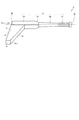
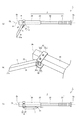
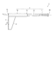
図1は、本発明の一実施の形態における打撃練習用バット1の構成を示す斜視図である。図2は、打撃練習用バット1の各部材の位置および大きさを説明する図である。図2(a)は、本体2の中心軸CLおよび打撃部3の突出方向に対して直交する所定の方向(以降、上方向と記すことがある)から見た場合の平面図である。図2(b)は、打撃練習用バット1の一部の部材の中心軸CLに沿った位置関係を示す図である。
FIG. 1 is a perspective view showing the configuration of a
図1および図2を参照して、本実施の形態における打撃練習用バット1は、本体2と、打撃部3とを備えている。本体2および打撃部3は、ホワイトアッシュ、アオダモ、トネリコ、もしくはヤチダモなどの木材、アルミニウム、銅、および亜鉛などを含む合金、または炭素繊維などよりなっている。本体2および打撃部3は、互いに異なる材料よりなっていてもよいし、同一の材料よりなっていてもよい。
With reference to FIGS. 1 and 2, a
本体2は、基端部2aから先端部2bまで直線状の中心軸CLに沿って延在している。本体2は、把持部21と、テーパー部22と、移行部23と、矩形部24とを備えている。
The
把持部21は、打者によって把持される部分であり、基端部2a付近に設けられている。把持部21には、滑り止め用のテープが巻き回されている。把持部21は、中心軸CLに直交する断面で見た場合に円形状を有している。把持部21の断面の直径は、把持部21における中心軸CL方向の所定の位置において極小となっており、その所定の位置からテーパー部22および基端部2aの各々に向かってわずかに増加している。
The
テーパー部22は、把持部21と先端部2b側で隣接している。テーパー部22は、中心軸CLに直交する断面で見た場合に円形状を有している。テーパー部22の断面の直径は、基端部2aから遠ざかるに従って(先端部2bに向かって)増加している。
The
移行部23は、テーパー部22と先端部2b側で隣接しており、テーパー部22と矩形部24との間に設けられている。移行部23は、中心軸CLに直交する断面で見た場合に、その形状が円形状から矩形状に変化している。
The
矩形部24は、先端部2b付近に設けられている。矩形部24は、中心軸CLに直交する断面で見た場合に矩形状を有している。矩形部24における先端部2b側の領域には打撃部3が設けられている。本実施の形態では打撃部3は本体2に固定されている。矩形部24の先端部2bの面は、平面になっている。
The
打撃部3は本体2から突出している。打撃部3は、上方向から見た場合に台形の形状を有しており、本体2から離れるに従ってその幅W(中心軸CLに沿った方向の長さ)が一定の割合で減少している。打撃部3は、打撃面31と、背面32と、固定面33と、突出面34とを含んでいる。打撃面31は、基端部2aに面しており、少なくとも打撃練習用バット1によるボールの打撃時において、上方向から見た場合に直線状に延在している。また、少なくとも打撃練習用バット1によるボールの打撃時において、上方向から見た場合に、打撃面31と基端部2a側の中心軸CLとがなす角度θは、90度以上180度未満であり、好ましくは110度以上130度以下である。
The
背面32は、打撃面31とは反対側に設けられている。背面32は平面であり、上方向から見た場合に中心軸CLに対して垂直に延在している。背面32と先端部2bの面とは同一平面上に存在している。
The
固定面33および突出面34はいずれも平面であり、上方向から見た場合に互いに平行である。固定面33において打撃部3は本体2に固定されている。打撃部3は接着などの方法で本体2に固定されている。突出面34は、打撃部3における中心軸CLから最も離れた位置に設けられている。
The fixed
特に図2を参照して、打撃部3が隣接する本体2の領域(固定面33が接触する本体2の領域)を領域RGとし、打撃面31における本体2から遠い側の端部を打撃面端部31aとし、打撃面端部31aの中心軸CLに沿った位置を位置Pとする。少なくとも打撃練習用バット1によるボールの打撃時において、先端部2bは領域RGの基端部2a側の始点位置Rよりも基端部2aから離れている。好ましくは、先端部2bは位置Pよりも基端部2aから離れている。これにより、打撃練習用バット1の形状が一般的なバットのように直線状に延在した形状に近づくので、打撃練習用バット1をスイングした打者に、一般的なバットをスイングした際の感覚に近い感覚を与えることができる。
Referring particularly to FIG. 2, the region of the
ここで、中心軸CLに沿った本体2全体の長さを長さL1とし、本体2から打撃面端部31aまでの距離(最短距離)を距離L2とし、中心軸CLに沿った固定面33の基端部2a側の端部の、中心軸CLに沿った基端部2aからの距離を距離L3とする。
Here, the length of the entire
距離L2は長さL1の30%以上45%以下であることが好ましい。距離L2を長さL1の30%以上とすることで、打撃面31として必要な面積を確保することができる。距離L2を長さL1の45%以下とすることで、スイングの際に打撃部3に加わる遠心力に起因して打者が感じ得る違和感を低減することができる。
The distance L2 is preferably 30% or more and 45% or less of the length L1. By setting the distance L2 to be 30% or more of the length L1, it is possible to secure a necessary area as the
また、領域RGは、中心軸CLに沿った基端部2aからの距離が長さL1の40%となる位置Q1(より好ましくは、中心軸CLに沿った基端部2aからの距離が長さL1の70%となる位置Q2)よりも先端部2b側に存在することが好ましい。これにより、把持部21と打撃面31との距離を確保することができ、打撃練習用バット1の使用時の安全性を向上することができる。
Further, in the region RG, the position Q1 at which the distance from the
なお、使用する打者の年齢または体格や、打撃練習用バット1の使用方法などに応じて、長さL1、距離L2、および距離L3、ならびに質量を適宜設定することができる。たとえば、打者が概ね中学生以上である場合には、長さL1は55cm以上65cm以下、距離L2は19cm以上23cm以下、距離L3は40cm以上50cm以下に、質量は820g以上920g以下に設定されてもよい。打者が概ね小学生以下である場合には、長さL1は45cm以上55cm以下、距離L2は14cm以上18cm以下、距離L3は30cm以上40cm以下、質量は650g以上750g以下に設定されてもよい。さらに、インサイドアウトのスイングを片手ずつ習得する際に用いる片手打ち専用のバットとして打撃練習用バット1を使用する場合には、長さL1は35cm以上40cm以下、距離L2は13cm以上17cm以下、距離L3は15cm以上25cm以下に、質量は400g以上500g以下に設定されてもよい。
The length L1, the distance L2, the distance L3, and the mass can be appropriately set according to the age or physique of the batter to be used, the usage method of the
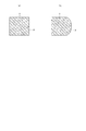
図3は、図2のIII−III線に沿った断面図である。図3の断面図は、打撃面31の延在方向に対して直交する断面図である。図3(a)は、打撃面31の断面形状の一の例であり、図3(b)は、打撃面31の断面形状の他の例である。
FIG. 3 is a cross-sectional view taken along the line III-III of FIG. The sectional view of FIG. 3 is a sectional view orthogonal to the extending direction of the
図3を参照して、打撃面31の延在方向に対して直交する断面で見た場合に、打撃面31は図3(a)に示すように平面よりなっていてもよいし、図3(b)に示すように弧形状を有していてもよい。特に図3(b)に示すように打撃面31が弧形状を有している場合には、打撃面31が一般的なバットの打撃面に近い形状となるため、打撃練習用バット1でボールを打った打者に、一般的なバットでボールを打った際の感覚に近い感覚を与えることができる。
Referring to FIG. 3, when viewed in a cross section orthogonal to the extending direction of the
[打撃練習用バットの使用方法] [How to use a batting practice bat]
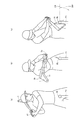
図4は、本発明の一実施の形態における打撃練習用バット1を用いて打者が正しいスイングを行った場合の打撃練習用バット1の動きを模式的に示す図である。図5は、本発明の一実施の形態における打撃練習用バット1を用いて打者が誤ったスイングを行った場合の打撃練習用バット1の動きを模式的に示す図である。
FIG. 4 is a diagram schematically showing the movement of the
図4を参照して、ボールBLはティーTA上に載置される。打者は、一度打撃面31をボールBLに接触させることで、ボールBLを打つ際の立ち位置を調整した後、打撃練習用バット1を構える。打者が正しいインサイドアウトのスイングを行う場合、打者は、打撃練習用バット1を構えた状態(図4(a))から、把持部21をトップまで移動させた後、基端部2aが打者の身体の中心の位置を最短の距離で通過し、次いで先端部2bが把持部21から遅れて打者の身体の中心の位置を通過するように打撃練習用バット1を移動させ(図4(b))、ティーTA上に載置されたボールBLを打撃面31で打つ(図4(c))。
With reference to FIG. 4, the ball BL is placed on the tee TA. The batter holds the
打者が打撃練習用バット1を用いて正しいインサイドアウトのスイングを行った場合、先端部2bが把持部21から遅れて打者の身体の中心の位置を通過するため、図4(c)に示すように、ボールBLを打つ瞬間の打撃面31は、正面方向(センター方向)CRを向くか、正面方向CRよりも流し打ち側(右打ちの場合のライト側、左打ちの場合のレフト側)を向く。その結果、ボールBLは正面方向CRに飛ぶか、正面方向CRよりも流し打ち側の領域DR1(右打ちの場合のライト側の領域、左打ちの場合のレフト側の領域)に飛ぶ。
When the batter makes a correct inside-out swing using the
一方、アウトサイドインのスイングや、手首を返す(トップハンドとなる手の甲を上に向ける)スイングなどの誤ったスイングを打者が行う場合、打者は、打撃練習用バット1を構えた状態(図5(a))から、把持部21をトップまで移動させた後、先端部2bが把持部21とほぼ同時に打者の身体の中心の位置を通過するように打撃練習用バット1を移動させ(図5(b))、ティーTAに載置されたボールBLを打撃面31で打つ(図5(c))。
On the other hand, when the batter makes a wrong swing such as an outside-in swing or a swing in which the wrist is turned back (the back of the hand that is the top hand is turned up), the batter holds the batting practice bat 1 (FIG. 5). From (a), after moving the
打者が打撃練習用バット1を用いて誤ったスイングを行った場合、先端部2bが打者の身体の中心の位置を通過するタイミングが早いため、図5(c)に示すように、ボールBLを打つ瞬間の打撃面31は、正面方向(センター方向)CRよりも引張り打ち側(右打ちの場合のレフト側、左打ちの場合のライト側)を向く。その結果、ボールBLは正面方向CRよりも引張り打ち側の領域DR2(右打ちの場合のレフト側の領域、左打ちの場合のライト側の領域)に飛ぶ。なお、手首を返すスイングは、打ったボールがドライブ回転し、ボールの飛距離が低下するため、好ましくない。
When the batter makes an incorrect swing using the
[実施の形態の効果] [Effect of Embodiment]
上述の実施の形態によれば、打者は、打撃練習用バット1でティーバッティングを行い、ボールが飛んだ方向に基づいて、自身のスイングが正しいインサイドアウトのスイングになっているか否かを確認することができる。その結果、インサイドアウトのスイングを効率的に習得することができる。
According to the above-described embodiment, the batter performs tee batting with the
インサイドアウトのスイングを習得することで、さらに次の効果を得ることができる。テイクバック(バットを構えた状態から把持部をトップまで移動させる動作)を十分にとるスイング(絶妙な間を作るスイング)を身に着けることができる。手首を返すスイングを矯正することができる。ボールの打点を身体に近づけることができ、後ろ手でボールを押しこむようなスイングを身に着けることができる。ボールの内側を打つイメージのスイングや、ボールを面で捉えるイメージのスイングを身に着けることができる。フルスイング時(ヒッティング時)のバットスピードを増加させることができる。 By learning the inside-out swing, you can obtain the following effects. It is possible to wear a swing (swing that creates an exquisite interval) that takes a sufficient takeback (an operation of moving the grip portion to the top from the state of holding the bat). The swing that returns the wrist can be corrected. The hitting point of the ball can be brought closer to the body, and the player can wear a swing that pushes the ball in his back. You can wear the swing of hitting the inside of the ball and the swing of catching the ball on the surface. You can increase the bat speed during a full swing (hit).
[変形例] [Modification]
続いて、上述の実施の形態の変形例について説明する。なお、各変形例において、説明した以外の打撃練習用バット1の構成は、上述の実施の形態における打撃練習用バットの構成と同一であるため、同一の部材には同一の符号を付し、その説明は繰り返さない。
Subsequently, a modified example of the above-described embodiment will be described. In addition, in each modified example, the configuration of the
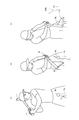
図6は、本発明の第1の変形例における打撃練習用バット1の構成を示す図である。図6(a)は、打撃部3が本体2に対して開いた状態を示す平面図である。図6(b)は、打撃部3が本体2に対して開いた状態における開閉部材4付近の拡大図である。図6(c)は、打撃部3が本体2に対して閉じた状態を示す平面図である。
FIG. 6 is a diagram showing a configuration of a
図6を参照して、第1の変形例の打撃練習用バット1は、開閉部材4をさらに備えている。開閉部材4は、打撃部3が本体2に対して開いた状態(図6(a))と、打撃部3が本体2に対して閉じた状態(図6(c))との各々で、打撃部3を保持する。
With reference to FIG. 6, the
開閉部材4は、固定側部材41と、揺動側部材42とを含んでいる。固定側部材41はU字形状を有する本体部41aと、2つの軸穴41bとを含んでいる。本体部41aは矩形部24と係合しており、ネジやボルトにより矩形部24に固定されている。本体部41aのU字の両端部付近は、矩形部24から打撃部3側に突出している。2つの軸固定穴41bは、本体部41aのU字の両端部付近に設けられている。
The opening/closing
揺動側部材42は、軸42aと、本体42bとを含んでいる。軸42aは、2つの軸穴41bに両端部が挿入されており、固定側部材41に対して搖動可能に支持されている。本体42bは軸42aに固定されている。本体42bは板状であり、打撃部3における打撃面31にネジやボルトにより固定されている。
The swing-
なお、打撃練習用バット1に開閉部材4を設ける場合には、開閉部材4による質量の増加を抑止するために、打撃面31と背面32とが互いに平行になる程度まで背面32側を削ることで、打撃部3の容積が減じられてもよい。また。先端部2bが、打撃面端部31aの中心軸CLに沿った位置Pと始点位置Rとの間に位置する程度まで、本体2の長さが減じられてもよい。
When the hitting
打撃練習用バット1の使用時には、打者は打撃部3を本体2に対して開いた状態にする。打撃部3が本体2に対して開いた状態では、打撃練習用バット1の構成は上述の実施の形態の場合とほぼ同じ構成となる。すなわち、打撃部3は本体2から突出した状態で本体2に固定される。打撃面31と基端部2a側の中心軸CLとがなす角度θは、90度以上180度未満となる。
When using the
一方、打撃練習用バット1の非使用時(打撃練習用バット1の搬送時など)には、打者は打撃部3を本体2に対して閉じた状態にする。打撃部3が本体2に対して閉じた状態では、打撃部3が本体2側に折りたたまれた状態で本体2に固定される。打撃面31と基端部2a側の中心軸CLとがなす角度θは、ほぼ0度になる。
On the other hand, when the
さらに、打撃練習用バット1の使用時には、打撃練習用バット1は次の方法で使用されてもよい。打者は打撃部3を本体2に対して閉じた状態で打撃練習用バット1を構え、フルスイングを行う。打者が適切な間をおいて正しいフルスイングを行った場合には、打撃部3に十分な大きさの遠心力が加わり、打撃部3は揺動する。その結果、打撃練習用バット1によるボールの打撃時には、打撃部3は本体2に対して開いた状態となる。一方、打者が適切な間をおかずに誤ったフルスイングを行った場合には、打撃部3に加わる遠心力が小さく、打撃部3は本体2に対して閉じた状態のままとなる。
Furthermore, when using the
第1の変形例によれば、打撃練習用バット1の非使用時に打撃部3を折りたたむことができるため、打撃練習用バット1の搬送が容易になる。また、打者が打撃部3を閉じた状態でフルスイングを行う場合には、適切な間をおいて正しいフルスイングを行ったか否かを、打者自身が容易に確認することができる。
According to the first modification, since the hitting
図7は、本発明の第2の変形例における打撃練習用バット1の構成を示す平面図である。
FIG. 7 is a plan view showing the configuration of the
図7を参照して、第2の変形例の打撃練習用バット1において、打撃部3は中空部35を含んでいる。上方向から見た場合に、中空部35はたとえば台形の平面形状を有している。中空部35の平面形状は任意である。
Referring to FIG. 7, in the
なお、上方向から見た場合に、打撃部3は任意の平面形状を有していればよく、台形の平面形状の代わりに三角形の平面形状を有していてもよい。言い換えれば、打撃部3は突出面34を含まず、点線で示すような尖った突出部Kを有していてもよい。
When viewed from above, the
第2の変形例によれば、中空部35を設けることにより打撃部3の質量を低減することができる。これにより、打撃練習用バット1の重心位置が一般的なバットの重心位置に近づき、打撃練習用バット1の総重量を軽くすることができるので、打撃練習用バット1をスイングした打者に、一般的なバットをスイングした際の感覚に近い感覚を与えることができる。
According to the second modified example, by providing the
図8は、本発明の第3の変形例における打撃練習用バット1の構成を示す平面図である。
FIG. 8 is a plan view showing the configuration of the
図8を参照して、第3の変形例の打撃練習用バット1は、固定部5をさらに備えている。固定部5は、本体2の先端部2bおよび打撃部3の背面32に接着などの方法で固定されている。固定部5は、板状であり、本体2の先端部2bから中心軸CLに対して直交する方向に延在している。固定部5は、本体2または打撃部3と同一の材料よりなっていてもよいし、本体2および打撃部3とは異なる材料よりなっていてもよい。
Referring to FIG. 8, the
第3の変形例によれば、打撃部3を本体2に対して強固に固定することができ、打撃部3を補強することができる。
According to the third modification, the
[その他] [Other]
上述の実施の形態および変形例は、適宜組み合わせることができる。 The above-described embodiments and modifications can be combined as appropriate.
上述の実施の形態および変形例は、すべての点で例示であって制限的なものではないと考えられるべきである。本発明の範囲は上記した説明ではなくて特許請求の範囲によって示され、特許請求の範囲と均等の意味および範囲内でのすべての変更が含まれることが意図される。 It should be considered that the above-described embodiments and modified examples are illustrative in all points and not restrictive. The scope of the present invention is shown not by the above description but by the claims, and is intended to include meanings equivalent to the claims and all modifications within the scope.
1 打撃練習用バット
2 本体
2a 本体の基端部
2b 本体の先端部
3 打撃部
4 開閉部材
5 固定部
21 把持部
22 テーパー部
23 移行部
24 矩形部
31 打撃部の打撃面
31a 打撃面端部
32 打撃部の背面
33 打撃部の固定面
34 打撃部の突出面
35 打撃部の中空部
41 開閉部材の固定側部材
41a 固定側部材の本体部
41b 固定側部材の軸穴
42 開閉部材の揺動側部材
42a 揺動側部材の軸
42b 揺動側部材の本体
BL ボール
CL 中心軸
CR 正面方向
DR1 流し打ち側の領域
DR2 引張り打ち側の領域
K 突出部
L1 中心軸に沿った本体全体の長さ
L2 本体から打撃面端部までの距離
L3 中心軸に沿った基端部からの距離
P 打撃面端部の中心軸に沿った位置
Q1 中心軸に沿った基端部からの距離が本体全体の長さの40%となる位置
Q2 中心軸に沿った基端部からの距離が本体全体の長さの70%となる位置
RG 打撃部が隣接する本体の領域
R 打撃部が隣接する本体の領域の基端部側の始点位置
TA ティー
W 上方向から見た場合の打撃部3の幅
θ 打撃面と基端部側の中心軸とがなす角度
1 Bat for hitting practice 2 Main body 2a Base end part of main body 2b Front end part of main body 3 Hitting part 4 Opening/closing member 5 Fixed part 21 Gripping part 22 Tapered part 23 Transition part 24 Rectangular part 31 Hitting surface 31a Hitting surface end part 32 Back face of striking part 33 Fixing surface of striking part 34 Projecting surface of striking part 35 Hollow part of striking part 41 Fixed side member of opening/closing member 41a Main body part of fixing side member 41b Shaft hole of fixing side member 42 Swinging of opening/closing member Side member 42a Shaft side member shaft 42b Swing side member main body BL Ball CL Central axis CR Front direction DR1 Flowing side area DR2 Pulling side area K Projection L1 Overall length of the main body along the central axis L2 Distance from the body to the end of the striking surface L3 Distance from the base end along the center axis P Position of the end of the striking surface along the center axis Q1 Distance from the base end along the center axis is the entire body Position where 40% of the length is reached Q2 Position where the distance from the base end along the central axis is 70% of the entire length of the body RG Region of the body where the striking part is adjacent R Region of the body where the striking part is adjacent Starting point position on the base end side TA tee W Width of the striking part 3 when viewed from above θ Angle formed by the striking face and the central axis on the base end side
Claims (8)
基端部から先端部まで直線状の中心軸に沿って延在する本体であって、前記基端部付近に設けられた把持部を含む本体と、
前記本体から突出し、打撃面を含む打撃部とを備え、
少なくとも前記打撃練習用バットによるボールの打撃時において、前記中心軸および前記打撃部の突出方向に対して直交する方向から見た場合に、前記打撃面は直線状に延在し、前記打撃面と前記基端部側の前記中心軸とは90度以上180度未満の角度をなし、
少なくとも前記打撃練習用バットによるボールの打撃時において、前記先端部は、前記打撃部が隣接する前記本体の領域の前記基端部側の始点位置よりも前記基端部から離れている、打撃練習用バット。 A bat for hitting practice,
A main body extending along a straight central axis from the base end to the tip, the main body including a grip provided near the base end,
Providing a striking portion including a striking surface, protruding from the main body,
At least at the time of hitting the ball with the hitting bat, the hitting surface extends linearly when viewed from a direction orthogonal to the projecting direction of the center axis and the hitting portion, and the hitting surface An angle of 90 degrees or more and less than 180 degrees is formed with the central axis on the base end side,
At least at the time of hitting the ball with the hitting bat, the tip end portion is farther from the base end portion than the starting point position on the base end portion side of the region of the main body to which the hitting portion is adjacent, For bat.
前記把持部と前記先端部側で隣接し、前記中心軸に直交する断面で見た場合に円形状を有し、前記基端部から遠ざかるに従って直径が増加する部分であるテーパー部と、
前記先端部付近に設けられ、前記中心軸に直交する断面で見た場合に矩形状を有する矩形部と、
前記テーパー部と前記矩形部との間に設けられ、前記中心軸に直交する断面で見た場合の形状が円形状から矩形状に変化する移行部とをさらに含む、請求項1〜7のいずれかに記載の打撃練習用バット。 The body is
A taper portion that is adjacent to the grip portion on the distal end side, has a circular shape when viewed in a cross section orthogonal to the central axis, and is a portion whose diameter increases as the distance from the base end portion increases,
A rectangular portion provided near the tip portion and having a rectangular shape when viewed in a cross section orthogonal to the central axis,
8. The method according to claim 1, further comprising: a transition portion that is provided between the tapered portion and the rectangular portion and that changes in shape from a circular shape to a rectangular shape when viewed in a cross section orthogonal to the central axis. A batting practice bat described in the crab.
Priority Applications (1)
| Application Number | Priority Date | Filing Date | Title |
|---|---|---|---|
| JP2018129869A JP6716640B2 (en) | 2018-07-09 | 2018-07-09 | Hitting bat |
Applications Claiming Priority (1)
| Application Number | Priority Date | Filing Date | Title |
|---|---|---|---|
| JP2018129869A JP6716640B2 (en) | 2018-07-09 | 2018-07-09 | Hitting bat |
Publications (2)
| Publication Number | Publication Date |
|---|---|
| JP2020005900A JP2020005900A (en) | 2020-01-16 |
| JP6716640B2 true JP6716640B2 (en) | 2020-07-01 |
Family
ID=69149481
Family Applications (1)
| Application Number | Title | Priority Date | Filing Date |
|---|---|---|---|
| JP2018129869A Active JP6716640B2 (en) | 2018-07-09 | 2018-07-09 | Hitting bat |
Country Status (1)
| Country | Link |
|---|---|
| JP (1) | JP6716640B2 (en) |
Family Cites Families (5)
| Publication number | Priority date | Publication date | Assignee | Title |
|---|---|---|---|---|
| US5150897A (en) * | 1990-12-04 | 1992-09-29 | Alex Wortman | Sport striking articles |
| US5213324A (en) * | 1991-12-06 | 1993-05-25 | Bowers Glen H | Practice sleeve and ball |
| JP3175571U (en) * | 2012-02-29 | 2012-05-17 | カワイチ株式会社 | Training bat |
| JP3194564U (en) * | 2014-09-18 | 2014-11-27 | 信仁 松川 | Easy meat bat |
| US9795850B1 (en) * | 2016-08-01 | 2017-10-24 | Gregory Sancier | Ball striking training device |
-
2018
- 2018-07-09 JP JP2018129869A patent/JP6716640B2/en active Active
Also Published As
| Publication number | Publication date |
|---|---|
| JP2020005900A (en) | 2020-01-16 |
Similar Documents
| Publication | Publication Date | Title |
|---|---|---|
| EP2389232B1 (en) | Golf club assembly and golf club head with bar and weighted member | |
| KR20060025532A (en) | Golf swing practice apparatus and method | |
| US9233290B2 (en) | Wrist training device for a golf swing and putting stroke | |
| JP2019506266A (en) | Sports training aid | |
| US8663024B2 (en) | Golf setup and swing training aid | |
| KR101031532B1 (en) | Golf club head | |
| KR100913823B1 (en) | Slice Prevention Golf Gloves | |
| JP6716640B2 (en) | Hitting bat | |
| JP5529330B1 (en) | Golf gloves | |
| CN103282086A (en) | A golf club in which a fixed shaft position under the grip forms the dynamic center of gravity of the golf swing | |
| US5560600A (en) | Method for and racket to teach tennis | |
| KR101781892B1 (en) | Golf Swing Training Equipments | |
| JP5385626B2 (en) | Golf practice equipment | |
| US5842930A (en) | Flexi-grip golf club | |
| KR100414618B1 (en) | Sweet spot tape for correcting hitting point of golf | |
| US9308428B1 (en) | Golf training aid | |
| KR20160099228A (en) | Golf club for exercise swing | |
| KR100976273B1 (en) | Practice golf club | |
| KR101191346B1 (en) | Golf glove with cock angle guide | |
| JP2021078825A (en) | Batting practice device | |
| JP2018511432A (en) | Universal swing training device | |
| KR102243051B1 (en) | Golf finger gloves and golf swing method using the same | |
| KR200419841Y1 (en) | Golf posture correction aid | |
| JP3219015U (en) | Golf practice equipment | |
| JP2010094478A (en) | Training device |
Legal Events
| Date | Code | Title | Description |
|---|---|---|---|
| A131 | Notification of reasons for refusal |
Free format text: JAPANESE INTERMEDIATE CODE: A131 Effective date: 20191217 |
|
| A521 | Request for written amendment filed |
Free format text: JAPANESE INTERMEDIATE CODE: A523 Effective date: 20200213 |
|
| TRDD | Decision of grant or rejection written | ||
| A01 | Written decision to grant a patent or to grant a registration (utility model) |
Free format text: JAPANESE INTERMEDIATE CODE: A01 Effective date: 20200512 |
|
| A61 | First payment of annual fees (during grant procedure) |
Free format text: JAPANESE INTERMEDIATE CODE: A61 Effective date: 20200610 |
|
| R150 | Certificate of patent or registration of utility model |
Ref document number: 6716640 Country of ref document: JP Free format text: JAPANESE INTERMEDIATE CODE: R150 |
|
| R250 | Receipt of annual fees |
Free format text: JAPANESE INTERMEDIATE CODE: R250 |
|
| R250 | Receipt of annual fees |
Free format text: JAPANESE INTERMEDIATE CODE: R250 |
|
| R250 | Receipt of annual fees |
Free format text: JAPANESE INTERMEDIATE CODE: R250 |