JP6713005B2 - Resistance heater with temperature detection power supply pin - Google Patents
Resistance heater with temperature detection power supply pin Download PDFInfo
- Publication number
- JP6713005B2 JP6713005B2 JP2017561912A JP2017561912A JP6713005B2 JP 6713005 B2 JP6713005 B2 JP 6713005B2 JP 2017561912 A JP2017561912 A JP 2017561912A JP 2017561912 A JP2017561912 A JP 2017561912A JP 6713005 B2 JP6713005 B2 JP 6713005B2
- Authority
- JP
- Japan
- Prior art keywords
- heater
- power supply
- power
- pin
- supply pin
- Prior art date
- Legal status (The legal status is an assumption and is not a legal conclusion. Google has not performed a legal analysis and makes no representation as to the accuracy of the status listed.)
- Active
Links
Images


Classifications
-
- H—ELECTRICITY
- H05—ELECTRIC TECHNIQUES NOT OTHERWISE PROVIDED FOR
- H05B—ELECTRIC HEATING; ELECTRIC LIGHT SOURCES NOT OTHERWISE PROVIDED FOR; CIRCUIT ARRANGEMENTS FOR ELECTRIC LIGHT SOURCES, IN GENERAL
- H05B1/00—Details of electric heating devices
- H05B1/02—Automatic switching arrangements specially adapted to apparatus ; Control of heating devices
- H05B1/0202—Switches
-
- H—ELECTRICITY
- H05—ELECTRIC TECHNIQUES NOT OTHERWISE PROVIDED FOR
- H05B—ELECTRIC HEATING; ELECTRIC LIGHT SOURCES NOT OTHERWISE PROVIDED FOR; CIRCUIT ARRANGEMENTS FOR ELECTRIC LIGHT SOURCES, IN GENERAL
- H05B3/00—Ohmic-resistance heating
- H05B3/02—Details
- H05B3/06—Heater elements structurally combined with coupling elements or holders
-
- H—ELECTRICITY
- H05—ELECTRIC TECHNIQUES NOT OTHERWISE PROVIDED FOR
- H05B—ELECTRIC HEATING; ELECTRIC LIGHT SOURCES NOT OTHERWISE PROVIDED FOR; CIRCUIT ARRANGEMENTS FOR ELECTRIC LIGHT SOURCES, IN GENERAL
- H05B1/00—Details of electric heating devices
- H05B1/02—Automatic switching arrangements specially adapted to apparatus ; Control of heating devices
- H05B1/0227—Applications
- H05B1/0252—Domestic applications
- H05B1/0258—For cooking
- H05B1/0261—For cooking of food
-
- H—ELECTRICITY
- H05—ELECTRIC TECHNIQUES NOT OTHERWISE PROVIDED FOR
- H05B—ELECTRIC HEATING; ELECTRIC LIGHT SOURCES NOT OTHERWISE PROVIDED FOR; CIRCUIT ARRANGEMENTS FOR ELECTRIC LIGHT SOURCES, IN GENERAL
- H05B3/00—Ohmic-resistance heating
- H05B3/0014—Devices wherein the heating current flows through particular resistances
-
- H—ELECTRICITY
- H05—ELECTRIC TECHNIQUES NOT OTHERWISE PROVIDED FOR
- H05B—ELECTRIC HEATING; ELECTRIC LIGHT SOURCES NOT OTHERWISE PROVIDED FOR; CIRCUIT ARRANGEMENTS FOR ELECTRIC LIGHT SOURCES, IN GENERAL
- H05B3/00—Ohmic-resistance heating
- H05B3/10—Heater elements characterised by the composition or nature of the materials or by the arrangement of the conductor
- H05B3/18—Heater elements characterised by the composition or nature of the materials or by the arrangement of the conductor the conductor being embedded in an insulating material
-
- H—ELECTRICITY
- H05—ELECTRIC TECHNIQUES NOT OTHERWISE PROVIDED FOR
- H05B—ELECTRIC HEATING; ELECTRIC LIGHT SOURCES NOT OTHERWISE PROVIDED FOR; CIRCUIT ARRANGEMENTS FOR ELECTRIC LIGHT SOURCES, IN GENERAL
- H05B3/00—Ohmic-resistance heating
- H05B3/40—Heating elements having the shape of rods or tubes
- H05B3/42—Heating elements having the shape of rods or tubes non-flexible
- H05B3/48—Heating elements having the shape of rods or tubes non-flexible heating conductor embedded in insulating material
-
- H—ELECTRICITY
- H05—ELECTRIC TECHNIQUES NOT OTHERWISE PROVIDED FOR
- H05B—ELECTRIC HEATING; ELECTRIC LIGHT SOURCES NOT OTHERWISE PROVIDED FOR; CIRCUIT ARRANGEMENTS FOR ELECTRIC LIGHT SOURCES, IN GENERAL
- H05B3/00—Ohmic-resistance heating
- H05B3/40—Heating elements having the shape of rods or tubes
- H05B3/54—Heating elements having the shape of rods or tubes flexible
-
- H—ELECTRICITY
- H05—ELECTRIC TECHNIQUES NOT OTHERWISE PROVIDED FOR
- H05B—ELECTRIC HEATING; ELECTRIC LIGHT SOURCES NOT OTHERWISE PROVIDED FOR; CIRCUIT ARRANGEMENTS FOR ELECTRIC LIGHT SOURCES, IN GENERAL
- H05B2203/00—Aspects relating to Ohmic resistive heating covered by group H05B3/00
- H05B2203/014—Heaters using resistive wires or cables not provided for in H05B3/54
Description
本発明は、抵抗ヒータ、及び熱電対のような温度検出デバイスに関するものである。 The present invention relates to temperature sensing devices such as resistance heaters and thermocouples.
本節の文章は、本発明に関する背景情報を提供するに過ぎず、従来技術を構成しないことがある。 The text of this section merely provides background information related to the present invention and may not constitute prior art.
抵抗ヒータは、種々の用途において目標物及び/または環境に熱を供給するために使用される。現在技術において知られている抵抗ヒータの1つの種類はカートリッジヒータであり、一般にセラミックコアに巻かれた抵抗線加熱素子を有する。代表的なセラミックコアは、内部に電源/端子ピンが配置された2つの長手方向の孔を規定する。この抵抗線の第1の端部は一方の電源ピンに電気接続され、抵抗線の他方の端部は他方の電源ピンに電気接続されている。次に、このアセンブリを、開口端及び閉口端、あるいは2つの開口端を有するより大きな直径の管状の金属シース(鞘)内に挿入し、これによりシースと抵抗線/コアのアセンブリとの間に環状の空間を生み出す。酸化マグネシウム(MgO)等のような絶縁材料をシースの開口端内に注入して、抵抗線とシースの内面との間の空間を満たす。 Resistive heaters are used to provide heat to targets and/or the environment in various applications. One type of resistance heater known in the art is a cartridge heater, which typically has a resistance wire heating element wound on a ceramic core. A typical ceramic core defines two longitudinal holes within which power/terminal pins are located. The first end of the resistance wire is electrically connected to one power supply pin, and the other end of the resistance wire is electrically connected to the other power supply pin. The assembly is then inserted into a larger diameter tubular metal sheath having an open end and a closed end, or two open ends, which results in between the sheath and the resistance wire/core assembly. Create an annular space. An insulating material such as magnesium oxide (MgO) is injected into the open end of the sheath to fill the space between the resistance wire and the inner surface of the sheath.
シースの開口端を、例えば埋め込み化合物及び/または別個のシール(封止)部材を用いることによって封止する。次に、このアセンブリ全体を、例えばカシメによって、あるいは他の適切な工程によって縮小または圧縮してシースの直径を低減し、これによりMgOを圧縮して縮小し、セラミックコアを少なくとも部分的に押し潰して、ピンの周りのコアを圧壊して、良好な電気接触及び熱伝達を保証する。縮小されたMgOは、加熱素子とシースとの間に比較的良好な熱伝達経路を提供すると共に、シースを加熱素子から電気絶縁する。 The open end of the sheath is sealed, for example by using a potting compound and/or a separate sealing member. The entire assembly is then reduced or compressed, for example, by crimping or other suitable process, to reduce the diameter of the sheath, which in turn compresses and reduces MgO, at least partially crushing the ceramic core. To crush the core around the pins to ensure good electrical contact and heat transfer. The reduced MgO provides a relatively good heat transfer path between the heating element and the sheath and electrically insulates the sheath from the heating element.
ヒータを動作させるべき適切な温度を測定するために、別個の温度センサ、例えば熱電対をヒータ上またはヒータ付近に配置する。別個の温度センサをヒータ及びその環境に追加することは、費用がかかり、加熱システム全体に複雑性を加える。 A separate temperature sensor, such as a thermocouple, is placed on or near the heater to measure the appropriate temperature at which the heater should operate. Adding a separate temperature sensor to the heater and its environment is expensive and adds complexity to the overall heating system.
1つの形態ではヒータが提供され、このヒータは、第1導電材料製の第1電源ピンと、第1電源ピンの第1導電材料とは異種である第2導電材料製の第2電源ピンと、2つの端部を有し第1及び第2電源ピンの第1及び第2導電材料とは異なる材料製の抵抗加熱素子とを具えている。この抵抗加熱素子は、一方の端部に第1電源ピンとの第1接合部を形成し、他方の端部に第2電源ピンとの第2接合部を形成し、第1及び第2接合部における電圧の変化を検出してヒータの平均温度を測定する。他の形態では、このヒータは、電源ピンと通電するコントローラも含むヒータシステムの形で提供され、このコントローラは、第1及び第2接合部における電圧の変化を測定してヒータの平均温度を測定する。 In one form, a heater is provided that includes a first power supply pin made of a first conductive material and a second power supply pin made of a second conductive material that is dissimilar to the first conductive material of the first power supply pin. A resistive heating element having two ends and made of a material different from the first and second conductive materials of the first and second power pins. This resistance heating element forms a first joint with the first power supply pin at one end and a second joint with the second power supply pin at the other end. The change in voltage is detected and the average temperature of the heater is measured. In another form, the heater is provided in the form of a heater system that also includes a controller for energizing the power pins, the controller measuring the change in voltage at the first and second junctions to determine the average temperature of the heater. ..
他の形態では、少なくとも1つのヒータを制御する方法が提供され、この方法は、第1導電材料製の電力供給ピンに電力を供給し、第1導電材料とは異種である導電材料製の電力帰線ピンを通して電力を戻すための加熱モードを起動するステップと;電力供給ピンに電力を供給して、2つの端部を有し電力供給ピン及び電力帰線ピンの第1及び第2導電材料とは異なる材料製の抵抗加熱素子に電力を供給するステップであって、この抵抗加熱素子は第1の端部に電力供給ピンとの第1接合部を形成し、他方の端部に電力帰線ピンとの第2接合部を形成し、さらに、この電力を、電力帰線ピンを通して供給するステップと;第1及び第2接合部における電圧の変化を測定してヒータの平均温度を測定するステップと;測定した平均温度に基づいて、ヒータに供給される電力を必要に応じて段階的に調整するステップとを含む。この方法の他の形態では、電力を供給するステップを中断して、測定モードに切り換えるステップを実行して電圧の変化を測定し、これに続いて再び加熱モードに切り換える。 In another aspect, a method of controlling at least one heater is provided, the method supplying power to a power supply pin made of a first conductive material, the power being made of a conductive material different from the first conductive material. Activating a heating mode for returning power through the return pin; supplying power to the power supply pin and having two ends, first and second conductive material of the power supply pin and the power return pin Powering a resistance heating element made of a material different from that forming a first joint with a power supply pin at a first end and a power return line at the other end. Forming a second junction with the pin and supplying this power through the power return pin; measuring the change in voltage at the first and second junctions to measure the average temperature of the heater. Adjusting the electric power supplied to the heater stepwise as necessary based on the measured average temperature. In another form of the method, the step of supplying power is interrupted and the step of switching to the measurement mode is performed to measure the change in voltage and subsequently switching back to the heating mode.
さらに他の形態では、流体浸漬加熱用のヒータが提供され、このヒータは、流体中への浸漬用に構成された加熱部分を具え、この加熱部分は複数の抵抗加熱素子を具えている。少なくとも2つの非加熱部分がこの加熱部分と連続し、各非加熱部分は全長を規定し、複数の加熱素子に電気接続された対応する複数組の電源ピンを具えている。各組の電源ピンは、第1導電材料製の第1電源ピン、及び第1電源ピンの第1導電材料とは異種である第2導電材料製の第2電源ピンを具えている。第1電源ピンは、非加熱部分内で第2電源ピンに電気接続されて接合部を形成し、第2電源ピンは、加熱部分内に延びて対応する抵抗加熱素子に電気接続されている。第2電源ピンは、対応する抵抗加熱素子よりも大きい断面積を規定する。少なくとも2つの終端部が非加熱部分と連続し、複数の第1電源ピンが非加熱部分から出て終端部内に延びて、リード線及びコントローラに電気接続される。1つの形態では、抵抗加熱素子の各々が、第1及び第2電源ピンの第1及び第2導電材料とは異なる材料製であり、第1電源ピンと第2電源ピンとの接合部の各々が、非加熱部分の全長に沿った異なる位置に配置されて、流体表面の高さ(レベル、液位)を測定する。 In yet another form, a heater is provided for fluid immersion heating, the heater comprising a heating portion configured for immersion in a fluid, the heating portion comprising a plurality of resistive heating elements. At least two unheated portions are contiguous with the heated portions, each unheated portion defining a total length and having a corresponding set of power pins electrically connected to the plurality of heating elements. Each set of power pins comprises a first power pin made of a first conductive material and a second power pin made of a second conductive material that is different from the first conductive material of the first power pin. The first power supply pin is electrically connected to the second power supply pin in the unheated portion to form a joint, and the second power supply pin extends into the heated portion and is electrically connected to the corresponding resistance heating element. The second power pin defines a larger cross-sectional area than the corresponding resistance heating element. At least two terminations are continuous with the unheated portion and a plurality of first power pins extend out of the unheated portion into the terminations and are electrically connected to the leads and the controller. In one form, each of the resistance heating elements is made of a material different from the first and second conductive materials of the first and second power pins, and each of the junctions of the first and second power pins comprises: The height (level, liquid level) of the fluid surface is measured by being placed at different positions along the entire length of the unheated part.
さらに応用可能な領域は、本明細書中に提供する説明より明らかになる。これらの説明及び具体例は、例示目的を意図しているに過ぎず、本発明の範囲を限定することを意図していないことは明らかである。 Further areas of applicability will become apparent from the description provided herein. Obviously, these descriptions and examples are intended for illustrative purposes only and are not intended to limit the scope of the invention.
本発明をより良く理解することができるために、以下、本発明の種々の形態を例として挙げて、添付した図面を参照しながら説明する。 In order that the present invention may be better understood, various embodiments of the present invention will be described below as examples with reference to the accompanying drawings.
本明細書中に記載する図面は例示目的に過ぎず、多少なりとも本発明の範囲を限定することは意図していない。 The drawings described herein are for illustration purposes only and are not intended to limit the scope of the invention in any way.
詳細な説明
以下の説明は本質的に例示に過ぎず、本発明、その用途、または使用法を限定することは意図していない。図面全体を通して、対応する参照番号は、同様な、あるいは対応する部分及び特徴を示すものと理解されたい。
DETAILED DESCRIPTION The following description is merely exemplary in nature and is not intended to limit the invention, its application, or uses. Throughout the drawings, corresponding reference numbers should be understood to indicate similar or corresponding parts and features.
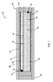
図1を参照すれば、本発明の教示によるヒータが例示され、その全体が参照番号20で示されている。この形態のヒータ20はカートリッジヒータであるが、本発明の教示は、本発明の範囲内に留まりつつ、以下でより詳細に説明する他の種類のヒータに適用することができることは明らかである。図に示すように、ヒータ20は、2つの端部24及び26を有する抵抗加熱素子22を具え、抵抗加熱素子22は、一例ではニクロム材料のような金属線の形態である。抵抗加熱素子22は、非導電性部分(あるいはこの形態ではコア)28の周りに巻回または配置されている。コア28は近端30及び遠端32を規定し、少なくとも近端30を通って延びる第1及び第2開口34及び36をさらに規定する。
Referring to FIG. 1, a heater in accordance with the teachings of the present invention is illustrated and generally designated by the
ヒータ20は、第1導電材料製の第1電源ピン40、及び第1電源ピン40の第1導電材料とは異なる第2導電材料製の第2電源ピン42をさらに具えている。さらに、抵抗加熱素子22は、第1及び第2電源ピン40及び42の第1及び第2導電材料とは異なる材料製であり、第1電源ピン40との接合部50を端部24に形成し、第2電源ピン42との接合部52を他方の端部26に形成する。抵抗加熱素子22は、接合部50において第1電源ピン40とは異なる材料であり、接合部52において第2電源ピン42とは異なる材料であるので、熱電対接合が効果的に形成され、これにより(以下でより詳細に説明するように)第1及び第2接合部50、52における電圧の変化を検出して、独立した
別個の温度センサを使用せずにヒータ20の平均温度を測定する。
The
1つの形態では、抵抗加熱素子22がニクロム材料であり、第1電源ピン40がクロメル(Chromel:登録商標)ニッケル合金であり、第2電源ピン42がアルメル(Alumel:登録商標)ニッケル合金である。その代わりに、第1電源ピン40は鉄とすることができ、第2電源ピン42はコンスタンタンとすることができる。三者(抵抗加熱素子、第1電源ピン、第2電源ピン)の材料が異なり、接合部50、52において熱電対接合が効果的に形成される限り、任意数の異なる材料及びその組合せを、抵抗加熱素子22、第1電源ピン40、及び第2電源ピン42用に用いることができることは、当業者にとって明らかである。本明細書中に記載する材料は例示に過ぎず、従って、本発明の範囲を限定するものとして考えるべきでない。
In one form, the
1つの用途では、ヒータ20の平均温度を用いて湿気の存在を検出することができる。湿気を検出した場合、湿気管理制御アルゴリズムを(以下でより詳細に説明する)コントローラにより実現して、ヒータ20を動作させ続けて早期故障に至り得るのではなく、湿気を被制御の様式で除去する。
In one application, the average temperature of the
さらに図示するように、ヒータ20は、非導電性部分28を包囲するシース(鞘)60、及び非導電性部分28の近端30に配置され、少なくとも部分的にシース内に延びてヒータ・アセンブリを完成させるシール部材62を含む。これに加えて、誘電体の充填材料64が抵抗加熱素子22とシース60との間に配置されている。カートリッジヒータの種々の構成、及びさらなる構造的及び電気的詳細は、米国特許第2831951号明細書(特許文献1)及び米国特許第3970822号明細書(特許文献2)に記載され、これらの特許は本願と同一の出願人に特許付与され、それらの内容は全文を参照する形で本明細書に含める。従って、本明細書中に例示する形態は例示に過ぎず、本発明の範囲を限定するものとして考えるべきでないことは明らかである。
As further shown, the
ここで図2を参照すれば、本発明は、電源ピン40、42と通電し、第1及び第2接合部50、52における電圧の変化を測定するように構成されたコントローラ70をさらに含む。より具体的には、コントローラ70は接合部50、52におけるミリボルト(mV)単位の変化を測定し、次にこれらの電圧の変化を用いてヒータ20の平均温度を測定する。1つの形態では、コントローラ70は、接合部50、52における電圧の変化を、抵抗加熱素子22への電力を遮断することなしに測定する。このことは、例えばAC入力電力信号のゼロ交差点における読み取り値を取得することによって達成することができる。他の形態では、電力が遮断され、コントローラ70は加熱モードから測定モードへ切り換わって電圧の変化を測定する。一旦、平均温度を測定すると、コントローラ70は再び加熱モードへ切り換わり、加熱モードは以下でより詳細に説明する。より具体的には、1つの形態では、トライアックを用いてAC電力をヒータ20へ切り換え、温度情報は電力信号のゼロ交差点またはその付近で生成される。本発明の範囲内に留まりつつ、AC切り換え装置の他の形態を用いることができ、従って、トライアックの使用は例示に過ぎず、本発明の範囲を限定するものとして考えるべきでない。
Referring now to FIG. 2, the present invention further includes a
その代わりに、図3に示すように、FET72を、スイッチングデバイス、及びこのFETのオフ期間中にDC電源による電圧を測定する手段として用いる。1つの形態では、3つの比較的大きな抵抗器73、74、及び75を用いて、測定回路76用の保護回路を形成する。こうした切り換え及び測定回路は例示に過ぎず、本発明の範囲を限定するものとして考えるべきでないことは明らかである。
Instead, as shown in FIG. 3,
再び図2を参照すれば、一対のリード線80が第1電源ピン40及び第2電源ピン42に接続されている。1つの形態では、リード線80が両方とも、一例では銅のような同じ材料である。リード線80を設けて、コントローラ70に達するのに必要な電源ピンの長さを低減すると共に、接合部82及び84において異なる材料により他の接合を導入する。この形態では、コントローラ70が電圧の変化を測定中の接合部を特定するために、信号線86及び88を用いて、コントローラ70が信号線86と88とを切り換えて、測定中の接合部を識別する。その代わりに、信号線86及び88をなくして、リード線の接合部82と84との間の電圧の無視するか、あるいはコントローラ70内のソフトウェアにより補償することができる。
Referring again to FIG. 2, the pair of
ここで図4を参照すれば、本発明の教示は、複数のゾーン90、92及び94を有するヒータ20’に適用することもできる。これらのゾーンの各々は、上述したように、それぞれの一組の電源ピン40’、42’、及び抵抗加熱素子22’を含む(明瞭にする目的でゾーン90のみを例示する)。こうした多ゾーン型ヒータ20’の1つの形態では、コントローラ70(図示せず)が、各ゾーンの端部96、98、及び100と通電して電圧変化を検出し、これによりその特定ゾーンの平均温度を測定する。その代わりに、コントローラ70が、端部96のみと通電してヒータ20’の平均温度を測定し、上述したように湿気が存在し得るか否かを特定することができる。3つのゾーンを示しているが、本発明の範囲内に留まりつつ任意数のゾーンを用いることができることは明らかである。
Referring now to FIG. 4, the teachings of the present invention may also be applied to heater 20' having
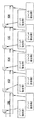
ここで図5を参照すれば、本発明の教示は複数の独立したヒータ100、102、104、106、及び108に適用することもでき、これらのヒータはカートリッジヒータとすることができ、これらのヒータは図に示すように順に接続されている。図に示すように、各ヒータは、抵抗加熱素子に至る異種の電源ピンの第1及び第2接合部を具え、これにより、上述したように各ヒータ100、102、104、106、及び108の平均温度をコントローラ70によって測定することができる。他の形態では、ヒータ100、102、104、106、及び108の各々が、それぞれの電力供給ピンを有し、単一の電力帰線ピンがすべてのヒータに接続されて、こうした多ヒータの実施形態の複雑性を低減する。カートリッジヒータによるこうした形態では、各コアが、それぞれに後続するヒータの電力供給ピンを収容するための通路を含む。
Referring now to FIG. 5, the teachings of the present invention may also be applied to multiple
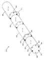
ここで図6及び7を参照すれば、本発明の他の形態により、抵抗加熱素子110のピッチを変化させて、ヒータ120に沿って調整された熱プロファイルを提供することができる。1つの形態(図5)では、抵抗加熱素子110がその全長に沿って連続的に変化するピッチを規定する。より具体的には、抵抗加熱素子110が連続的に変化するピッチを有して、直後に隣接する360度のコイルループ上で増加または減少するピッチP4〜P9に適合する能力を有する。抵抗加熱素子110の連続的に変化するピッチは、ヒータ面(例えば、シース112の表面)の流束密度に漸進的変化を与える。こうした連続的に変化するピッチの原理は、充填絶縁体114を有する環状ヒータに適用したものとして示すが、この原理はあらゆる種類のヒータに適用することもでき、それらは上述したカートリッジヒータを含むが、これに限定されない。これに加えて、上述したように、第1電源ピン122は第1導電材料製であり、第2電源ピン124は、第1電源電源ピン122の第1導電材料とは異種である第2導電材料製であるのに対し、抵抗加熱素子110は、第1及び第2電源ピン122、124の第1及び第2導電材料とは異なる材料製であり、これにより、第1及び第2接合部126、128における電圧の変化を検出してヒータ120の平均温度を測定する。
Referring now to FIGS. 6 and 7, according to another aspect of the present invention, the pitch of the
他の形態(図7)では、ゾーンA、B、及びC内で、それぞれピッチP1、P2、及びP3を有する。P3はP1よりも大きく、P1はP2よりも大きい。図に示すように、抵抗加熱素子130は、各ゾーンの全長に沿って一定のピッチを有する。同様に、第1電源ピン132は第1導電材料製であり、第2電源ピン134は、第1導電ピン132の第1導電材料とは異種である第2導電材料製であるのに対し、抵抗加熱素子130は第1及び第2電源ピン132、134の第1及び第2導電材料とは異なる材料製であり、これにより、第1及び第2接合部136、138における電圧の変化を検出して、ヒータ120の平均温度を測定する。
Another form (FIG. 7) has pitches P 1 , P 2 , and P 3 in zones A, B, and C, respectively. P 3 is greater than P 1, P 1 is greater than P 2. As shown, the
図8を参照すれば、本明細書中に説明するヒータ及び二重目的の電源ピンは多数の用途を有し、一例として熱交換器140を含む。熱交換器140は1つまたは複数の加熱素子142を含むことができ、加熱素子142の各々は、本発明の範囲内に留まりつつ、図示し上述したように、ゾーンまたは可変ピッチの抵抗加熱素子をさらに含むことができる。熱交換器の応用は例示に過ぎず、本発明の教示は、温度測定も必要としつつ熱を供給するあらゆる用途に用いることができることは、その温度が絶対的な温度であっても、上述した湿気の存在のような他の環境条件のための温度であっても、明らかである。
Referring to FIG. 8, the heater and dual purpose power supply pins described herein have numerous applications, including
図9に示すように、本発明の教示は、層状ヒータ150にような他の種類のヒータにも適用することができる。一般に、層状ヒータ150は、基板154に付加された誘電体層152、誘電体層152に付加された抵抗加熱層156、及び抵抗加熱層156の全体上に付加された保護層158を含む。接合部160は、抵抗層158のトレース(線)の一方の端部と第1リード線162との間に形成され(明瞭にする目的で一方の端部のみを示す)、同様に第2の接合部が他方の端部に形成され、上述した本発明の原理に従って、これらの端部における電圧変化を検出して、ヒータ150の平均温度を測定する。こうした層状ヒータは、米国特許第8680433号明細書(特許文献3)中に図示されてより詳細に説明され、この特許は本願と同一の出願人に特許付与され、その内容は全文を参照する形で本明細書に含める。
As shown in FIG. 9, the teachings of the present invention can be applied to other types of heaters, such as
本発明の教示によれば、上述したカートリッジ、管状、及び層状ヒータ以外の、あるいはこれらに加えて、他の種類のヒータを用いることもできる。これらの追加的な種類のヒータは、例としてポリマーヒータ、フレキシブルヒータ、電熱線、及びセラミックヒータを含むことができる。これらの種類のヒータは例示に過ぎず、本発明の範囲を限定するものとして考えるべきでないことは明らかである。 Other types of heaters may be used in addition to or in addition to the cartridge, tubular, and layered heaters described above, in accordance with the teachings of the present invention. These additional types of heaters can include, by way of example, polymer heaters, flexible heaters, heating wires, and ceramic heaters. Obviously, these types of heaters are merely exemplary and should not be considered as limiting the scope of the invention.
ここで図10を参照すれば、本発明の教示による、少なくとも1つのヒータを制御する方法が示されている。この方法は次のステップを含む: Referring now to FIG. 10, a method of controlling at least one heater according to the teachings of the present invention is shown. This method includes the following steps:
(A)第1導電材料製である電力供給ピンに電力を供給し、第1導電材料とは異種である導電材料製の電力帰線ピンを通して電力を戻すための加熱モードを起動するステップ; (A) powering a power supply pin made of a first conductive material and activating a heating mode for returning power through a power return pin made of a conductive material different from the first conductive material;
(B)電力供給ピンに電力を供給して、2つの端部を有し電力供給ピン及び電力帰線ピンの第1及び第2導電材料とは異なる材料製の抵抗加熱素子に電力を供給するステップであって、この抵抗加熱素子は一方の端部に電力供給ピンとの第1接合部を形成し、他方の端部に電力帰線ピンとの第2接合部を形成し、さらにこの電力を電力帰線ピンを通して供給するステップ; (B) Power is supplied to the power supply pin to supply a resistance heating element having two ends and made of a material different from the first and second conductive materials of the power supply pin and the power return pin. In this step, the resistance heating element forms a first joint with a power supply pin at one end and a second joint with a power return pin at the other end, Feeding through the return pin;
(C)第1及び第2接合部における電圧の変化を測定して、ヒータの平均温度を測定するステップ; (C) measuring the average temperature of the heater by measuring the change in voltage at the first and second junctions;
(D)測定した平均温度に基づいて、ヒータに供給される電力を必要に応じて段階的に調整するステップ;及び、 (D) stepwise adjusting the electric power supplied to the heater based on the measured average temperature, if necessary; and
(E)ステップ(A)〜(D)を反復するステップ。 (E) A step of repeating steps (A) to (D).
この方法の他の形態では、破線で示すように、コントローラが電圧の変化を測定するための測定モードに切り換えている間に、ステップ(B)を中断し、次にコントローラは再び加熱モードに切り換える。 In another form of this method, step (B) is interrupted while the controller is in the measurement mode for measuring the change in voltage, as indicated by the dashed line, and then the controller is again in the heating mode. ..
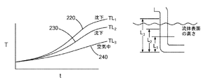
本発明のさらに他の形態を図11〜13に示し、これらの図では流体浸漬加熱用のヒータを例示し、その全体を参照番号200で示す。ヒータ200は、流体中への浸漬用に構成された加熱部分202を具え、加熱部分202は、複数の抵抗加熱素子204、及び加熱部分202と連続した少なくとも2つの非加熱部分206、208を具えている(図11には1つの非加熱部分206のみを示す)。各非加熱部分206、208は全長を規定し、複数の加熱素子204に電気接続された対応する複数組の電源ピンを具えている。より具体的には、電源ピンの各組は、第1導電材料製の第1電源ピン212、及び第1電源ピン212の第1導電材料とは異種である第2導電材料製の第2電源ピン214を具えている。第1電源ピン212は、非加熱部分206、208内で第2電源ピン214と電気接続されて、接合部220、230、及び240を形成する。さらに図示するように、第2電源ピン214は加熱部分202内に延びて、対応する抵抗加熱素子204に電気接続されている。さらに、第2電源ピン214は、対応する抵抗加熱素子204よりも大きい断面積を規定して、第2電源ピン24と抵抗加熱素子204との接続部に他の接合部も測定可能な量の熱も生成しない。
Yet another form of the present invention is illustrated in FIGS. 11-13, which exemplify a heater for fluid immersion heating, generally designated by the
さらに図示するように、終端部分250が非加熱部分206に連続し、複数の第1電源ピン212が非加熱部分206から出て終端部分250内に延びて、リード線及びコントローラ(図示せず)に電気接続される。前の説明と同様に、抵抗加熱素子204の各々が、第1及び第2電源ピン212、214の第1及び第2導電材料とは異なる材料製であり、第1電源ピン212と第2電源ピン214との接合部220、230、及び240は、非加熱部分206、208の全長に沿った異なる位置に配置されている。より具体的には、そして一例として、接合部220は距離L1の所に、接合部230は距離L2の所に、そして接合部240は距離L3の所にある。
As further shown, the
図13に示す、時刻「t」に伴う接合部220、230、及び240の温度では、接合部220は流体F中に沈下し、接合部230は流体中に沈下しているが接合部220ほど深くなく、そして接合部240は沈下していない。従って、接合部220、230、及び240の各々における電圧の変化を検出することにより、加熱部分202に対する流体表面の高さの指標を提供することができる。特に、流体が調理/揚げ物用途である際には、加熱部分202が動作中に発火しないように空気中に露出しないことが望ましい。本発明の教示による接合部220、230、及び240により、コントローラは、流体表面の高さが加熱部分202に近過ぎるか否かを判定し、これにより電力をヒータ200から遮断することができる。
At the temperatures of the
本例では3つの接合部220、230、及び240を図示しているが、接合部が加熱部分202内にないことを条件として、本発明の範囲内に留まりつつ任意数の接合部を用いることができることは明らかである。
Although three
ここで図14を参照すれば、本発明のさらに他の形態が、図に示すようにヒータシステム270の複数ゾーンの形に配置された複数のヒータコア300を含む。この例示的形態では、ヒータコア300は上述したようなカートリッジヒータであるが、本明細書中に記載したような他の種類のヒータを用いることもできることは明らかである。従って、本発明のこうした形態のカートリッジヒータの構成は、本発明の範囲を限定するものとして考えるべきでない。
Referring now to FIG. 14, yet another aspect of the present invention includes a plurality of
図に示すように、各ヒータコア300は、複数の電源ピン301、302、303、304、及び305を含む。上述した形態と同様に、電源ピンは異なる導電材料製であり、より具体的には、電源ピン301、304、及び305は第1導電材料製であり、電源ピン302、303、及び306は、第1導電材料とは異種である第2導電材料製である。さらに図示するように、少なくとも1本のジャンパ線320が異種の電源ピン間に、本例では電源ピン301と電源ピン303との間に接続されて、ジャンパ線320の位置に近接した位置の温度読み取り値を取得する。ジャンパ線320は、ジャンパ線320の位置に近接した位置の温度を示すミリボルト単位の信号を取得するのに十分な、例えばリード線または他の導電部材とすることができ、以上に図示して説明するようにコントローラ70とも通電する。任意数のジャンパ線320を異種の電源ピン間に用いることができ、他の位置は、電源ピン303と電源ピン305との間に、ゾーン3とゾーン4との間に例示する。
As shown, each
この例示的形態では、電源ピン301、303、及び305は、それぞれに隣接する電源ピン302、304、及び306との間のヒータ回路の中性脚部(端子)である。より具体的には、ゾーン1内のヒータ回路は電源ピン301と302との間にあり、これらの電源ピン間に抵抗加熱素子(例えば、図1に示す素子22)を有する。ゾーン2内のヒータ回路は電源ピン303と304との間にあり、これら2つの電源ピン間に抵抗加熱素子を有する。同様に、ゾーン3内のヒータ回路は電源ピン305と306との間にあり、これら2つの電源ピン間に抵抗加熱素子を有する。これらのヒータ回路は例示に過ぎず、図1を参照して上述したカートリッジヒータの教示に従い構成されることは明らかである。本発明の範囲内に留まりつつ、複数のヒータコア300及びゾーンを有するヒータ回路の任意数の構成を用いることができる。4つのゾーン及びカートリッジヒータの構成の図示は例示に過ぎず、本発明の範囲内に留まりつつ、上記異種の電源ピン及びジャンパ線は、他の種類のヒータと共に、そして異なる数及び/または構成のゾーンの形で用いることができることは明らかである。
In this exemplary form, power pins 301, 303, and 305 are the neutral legs (terminals) of the heater circuit between adjacent power pins 302, 304, and 306, respectively. More specifically, the heater circuit in
なお、本発明は、例として説明し図示した実施形態に限定されない。多種多様な変更を説明してきたが、より多数が当業者の知識の一部である。本発明及び本特許の保護の範囲から離れることなしに、これら及び他の変更、並びに技術的等価物による置き換えを、説明及び図面に加えることができる。
It should be noted that the present invention is not limited to the embodiments described and illustrated as examples. Although a wide variety of modifications have been described, the greater number is part of the knowledge of those skilled in the art. These and other changes and substitutions with technical equivalents may be made to the description and drawings without departing from the scope of protection of the invention and of this patent.
Claims (14)
前記第1電源ピンの前記第1導電材料とは異種である第2導電材料製の第2電源ピンと、
2つの端部を有する抵抗加熱素子であって、前記第1電源ピンの前記第1導電材料及び前記第2電源ピンの前記第2導電材料とは異なる材料製の抵抗加熱素子とを具えたヒータであって、
前記抵抗加熱素子は、一方の前記端部に前記第1電源ピンとの第1接合部を形成し、他方の前記端部に前記第2電源ピンとの第2接合部を形成し、
前記第1接合部及び前記第2接合部における電圧の変化を検出して、前記ヒータの平均温度を測定する、ヒータ。 A first power pin made of a first conductive material;
A second power supply pin made of a second conductive material different from the first conductive material of the first power supply pin;
A heater having a resistance heating element having two ends, the resistance heating element being made of a material different from the first conductive material of the first power supply pin and the second conductive material of the second power supply pin. And
The resistance heating element forms a first joint portion with the first power supply pin at one of the end portions, and forms a second joint portion with the second power supply pin at the other end portion,
A heater that detects a change in voltage at the first junction and the second junction and measures an average temperature of the heater.
近端及び遠端を規定し、少なくとも前記近端を通って延びる第1開口及び第2開口を有する非導電性部分と、
前記非導電性部分を包囲するシースと、
前記非導電性部分の前記近端に配置され、少なくとも部分的に前記シース内に延びるシール部材とをさらに具え、
前記第1電源ピン及び前記第2電源ピンが前記第1開口及び前記第2開口内に配置され、前記抵抗加熱素子が前記非導電性部分の周りに配置されている、請求項4に記載のヒータ。 The cartridge heater is
A non-conductive portion defining a near end and a far end and having at least a first opening and a second opening extending through the near end;
A sheath surrounding the non-conductive portion,
A seal member disposed at the proximal end of the non-conductive portion and extending at least partially within the sheath;
The first power pin and the second power pin are disposed within the first opening and the second aperture, and the resistive heating element is disposed around the non-conductive portion. heater.
流体中への浸漬用に構成された加熱部分であって、複数の前記抵抗加熱素子を具えた加熱部分と、
前記加熱部分と連続する少なくとも2つの非加熱部分と、
前記非加熱部分と連続する少なくとも2つの終端部分とを具え、
該非加熱部分の各々が、全長を規定し、前記複数の抵抗加熱素子に電気接続された対応する複数組の電源ピンを具え、
前記複数組の電源ピンの各組が、
前記第1電源ピンと、
前記第2電源ピンとを具え、
前記第1電源ピンは、前記非加熱部分内で前記第2電源ピンに電気接続されて接合部を形成し、前記第2電源ピンは、前記加熱部分内に延びて、対応する前記抵抗加熱素子に電気接続され、前記第2電源ピンは、対応する前記抵抗加熱素子よりも大きい断面積を規定し、
前記第1電源ピンは、前記非加熱部分から出て、前記終端部分内に延びて、リード線およびコントローラに電気接続され、
前記抵抗加熱素子の各々が、前記第1電源ピンの前記第1導電材料及び前記第2電源ピンの前記第2導電材料とは異なる材料製であり、前記第1電源ピンと前記第2電源ピンとの前記接合部の各々が、前記非加熱部分の前記全長に沿った異なる位置に配置されて、前記流体の表面の高さを検出する、ヒータ。 A heater for fluid immersion heating, comprising the heater according to claim 1.
A heating section configured for immersion in a fluid, the heating section comprising a plurality of said resistance heating elements,
At least two non-heated portions continuous with the heated portion,
A non-heated portion and at least two end portions that are continuous,
Each of the unheated portions defines a total length and comprises a corresponding set of power pins electrically connected to the plurality of resistive heating elements,
Each set of the plurality of sets of power pins,
The first power pin,
And a second power pin,
The first power supply pin is electrically connected to the second power supply pin in the unheated portion to form a joint, and the second power supply pin extends into the heated portion to correspond to the corresponding resistance heating element. Electrically connected to the second power supply pin, the second power supply pin defines a larger cross-sectional area than the corresponding resistive heating element,
The first power pin extends from the unheated portion and extends into the termination portion for electrical connection to a lead wire and a controller;
Each of the resistance heating elements is made of a material different from the first conductive material of the first power supply pin and the second conductive material of the second power supply pin, and the first power supply pin and the second power supply pin are connected to each other. A heater in which each of the joints is located at a different location along the length of the unheated portion to detect the height of the surface of the fluid.
各々がゾーンを規定する複数のヒータコアと、
前記ヒータコアの各々を通って延びる複数の電源ピンであって、互いに異なる導電材料製である複数の電源ピンと
2つの前記電源ピン間に接続され、前記電源ピンとは異種の材料製であるジャンパ線とを具え、
前記ジャンパ線は、前記ヒータシステムにおける当該ジャンパ線に近接した位置の温度読み取り値を取得するためのコントローラと通電する、ヒータシステム。
A heater system including the heater according to claim 1,
A plurality of heater cores each defining a zone,
A plurality of power supply pins extending through each of the heater cores, a plurality of power supply pins made of different conductive materials, and a jumper wire connected between the two power supply pins and made of a different material from the power supply pins; With
A heater system in which the jumper wire is energized with a controller for obtaining a temperature reading value at a position close to the jumper wire in the heater system.
Applications Claiming Priority (3)
| Application Number | Priority Date | Filing Date | Title |
|---|---|---|---|
| US14/725,537 US10728956B2 (en) | 2015-05-29 | 2015-05-29 | Resistive heater with temperature sensing power pins |
| US14/725,537 | 2015-05-29 | ||
| PCT/US2016/033754 WO2016196055A1 (en) | 2015-05-29 | 2016-05-23 | Resistive heater with temperature sensing power pins |
Publications (2)
| Publication Number | Publication Date |
|---|---|
| JP2018516436A JP2018516436A (en) | 2018-06-21 |
| JP6713005B2 true JP6713005B2 (en) | 2020-06-24 |
Family
ID=56137519
Family Applications (1)
| Application Number | Title | Priority Date | Filing Date |
|---|---|---|---|
| JP2017561912A Active JP6713005B2 (en) | 2015-05-29 | 2016-05-23 | Resistance heater with temperature detection power supply pin |
Country Status (11)
| Country | Link |
|---|---|
| US (5) | US10728956B2 (en) |
| EP (1) | EP3305014B1 (en) |
| JP (1) | JP6713005B2 (en) |
| KR (1) | KR102541916B1 (en) |
| CN (1) | CN107852778B (en) |
| BR (1) | BR112017025738A2 (en) |
| CA (1) | CA2987749C (en) |
| ES (1) | ES2784520T3 (en) |
| MX (1) | MX370150B (en) |
| TW (2) | TWI666966B (en) |
| WO (1) | WO2016196055A1 (en) |
Families Citing this family (16)
| Publication number | Priority date | Publication date | Assignee | Title |
|---|---|---|---|---|
| US20140349403A1 (en) * | 2011-12-12 | 2014-11-27 | The Children's Hospital Of Philadelphia | Large commercial scale lentiviral vector production system and vectors produced thereby |
| US11540358B2 (en) | 2015-05-29 | 2022-12-27 | Watlow Electric Manufacturing Company | Modular heater assembly with interchangeable auxiliary sensing junctions |
| US10728956B2 (en) | 2015-05-29 | 2020-07-28 | Watlow Electric Manufacturing Company | Resistive heater with temperature sensing power pins |
| CN111108350B (en) * | 2017-07-27 | 2022-09-16 | 沃特洛电气制造公司 | Sensor system and integrated heater-sensor for measuring and controlling heater system performance |
| US11920878B2 (en) * | 2017-08-28 | 2024-03-05 | Watlow Electric Manufacturing Company | Continuous helical baffle heat exchanger |
| US11913736B2 (en) * | 2017-08-28 | 2024-02-27 | Watlow Electric Manufacturing Company | Continuous helical baffle heat exchanger |
| KR20210007986A (en) * | 2018-04-11 | 2021-01-20 | 와틀로 일렉트릭 매뉴팩츄어링 컴파니 | Resistive heater with temperature sensing power pin and auxiliary sensing junction |
| CN110582003B (en) * | 2019-01-12 | 2020-10-27 | 安徽省安泰科技股份有限公司 | Compatible big data acquisition terminal |
| CN115943295A (en) * | 2020-04-08 | 2023-04-07 | 沃特洛电气制造公司 | Method for calibrating and monitoring the resistance of a thermal system |
| EP4189345A1 (en) * | 2020-07-27 | 2023-06-07 | Watlow Electric Manufacturing Company | Multipoint series sensor in electric heating elements |
| JP2023540531A (en) | 2020-09-04 | 2023-09-25 | ワットロー・エレクトリック・マニュファクチャリング・カンパニー | Method and system for the control of electric heaters using energy control |
| EP3993562A1 (en) * | 2020-10-30 | 2022-05-04 | Eichenauer Heizelemente GmbH & Co. KG | Heating cartridge with ceramic casting compound |
| WO2022159453A1 (en) | 2021-01-19 | 2022-07-28 | Watlow Electric Manufacturing Company | Method and system for detecting and diagnosing fluid line leakage for industrial systems |
| KR20220127171A (en) | 2021-03-10 | 2022-09-19 | 와틀로 일렉트릭 매뉴팩츄어링 컴파니 | Heater bundles having variable power output within zones |
| CN116420924A (en) * | 2022-01-04 | 2023-07-14 | 深圳市合元科技有限公司 | Gas mist generating device and resistance heater for gas mist generating device |
| EP4350269A1 (en) | 2022-09-28 | 2024-04-10 | Watlow Electric Manufacturing Company | Continuous helical baffle heat exchanger |
Family Cites Families (49)
| Publication number | Priority date | Publication date | Assignee | Title |
|---|---|---|---|---|
| GB197864A (en) | 1922-07-07 | 1923-05-24 | Ward Leonard Electric Co | Electric resistance device |
| US1833112A (en) * | 1925-07-09 | 1931-11-24 | Brown Instr Co | Thermoelectric liquid level indicator |
| US2831951A (en) | 1954-07-06 | 1958-04-22 | Watlow Electric Mfg | Cartridge heater and method of making same |
| US3118136A (en) * | 1958-02-03 | 1964-01-14 | Westinghouse Electric Corp | Liquid level indicator |
| US3360990A (en) * | 1964-12-31 | 1968-01-02 | Norman D. Greene | Thermoelectric liquid level indicating system |
| US3690955A (en) | 1969-06-16 | 1972-09-12 | Weston Instr Division | Thermoelectric converters and method of making same |
| US3654427A (en) | 1970-09-28 | 1972-04-04 | Alexander Schoenwald | Electric heated soldering tool |
| US4037463A (en) | 1974-07-10 | 1977-07-26 | Showa Denko Kabushiki Kaisha | Temperature-detecting element |
| US3970822A (en) | 1975-03-17 | 1976-07-20 | Watlow Electric Manufacturing Company | Electric cartridge heater |
| US4647710A (en) | 1982-02-26 | 1987-03-03 | Xco International, Inc. | Heat sensitive cable and method of making same |
| US4423309A (en) * | 1982-06-28 | 1983-12-27 | General Motors Corporation | Quick heat self regulating electric glow heater |
| JPS5916095U (en) * | 1982-07-20 | 1984-01-31 | 株式会社八光電機製作所 | sheath heater |
| US5043560A (en) | 1989-09-29 | 1991-08-27 | Masreliez C Johan | Temperature control of a heated probe |
| JPH088556Y2 (en) * | 1991-09-18 | 1996-03-06 | 株式会社八光電機製作所 | Cartridge heater group |
| FI107963B (en) | 1995-06-20 | 2001-10-31 | Instrumentarium Oy | infrared Radiator |
| US5714738A (en) * | 1995-07-10 | 1998-02-03 | Watlow Electric Manufacturing Co. | Apparatus and methods of making and using heater apparatus for heating an object having two-dimensional or three-dimensional curvature |
| US5864941A (en) * | 1996-05-22 | 1999-02-02 | Watlow Electric Manufacturing Company | Heater assembly method |
| JP3124506B2 (en) | 1997-03-14 | 2001-01-15 | 白光株式会社 | Heater / sensor complex |
| US6087631A (en) * | 1997-03-14 | 2000-07-11 | Hakko Corporation | Soldering iron with temperature control cycles related to rectified voltage cycles |
| US6147335A (en) * | 1997-10-06 | 2000-11-14 | Watlow Electric Manufacturing Co. | Electrical components molded within a polymer composite |
| US6124579A (en) * | 1997-10-06 | 2000-09-26 | Watlow Electric Manufacturing | Molded polymer composite heater |
| US6337470B1 (en) * | 1997-10-06 | 2002-01-08 | Watlow Electric Manufacturing Company | Electrical components molded within a polymer composite |
| US6219398B1 (en) * | 1998-07-28 | 2001-04-17 | Ce Nuclear Power Llc | Heated junction thermocouple cable arrangement |
| JP2000182750A (en) * | 1998-12-11 | 2000-06-30 | Hakko Electric Mach Works Co Ltd | Hot air generator |
| US6072165A (en) * | 1999-07-01 | 2000-06-06 | Thermo-Stone Usa, Llc | Thin film metal/metal oxide thermocouple |
| DE10004614A1 (en) * | 2000-02-03 | 2001-08-16 | Siemens Ag | Liquid pressure sensor esp. for detecting reducing agent solution pressure for exhaust-gas treatment in combustion engine - includes spring element for holding pressure sensor element in defined position in receptacle part for pressure sensor element |
| US6922017B2 (en) * | 2000-11-30 | 2005-07-26 | Matsushita Electric Industrial Co., Ltd. | Infrared lamp, method of manufacturing the same, and heating apparatus using the infrared lamp |
| JP3483544B2 (en) | 2000-12-13 | 2004-01-06 | 株式会社東海ヒット | Transparent surface temperature sensor and transparent surface temperature control device |
| US20020118032A1 (en) * | 2001-02-28 | 2002-08-29 | Schlumberger Technologies, Inc. | Heating apparatus containing an array of surface mount components for DUT performance testing |
| US7040397B2 (en) * | 2001-04-24 | 2006-05-09 | Shell Oil Company | Thermal processing of an oil shale formation to increase permeability of the formation |
| US7657961B2 (en) * | 2002-10-02 | 2010-02-09 | Sbr Investments Company Llc | Vehicle windshield cleaning system |
| US6740857B1 (en) | 2002-12-06 | 2004-05-25 | Chromalox, Inc. | Cartridge heater with moisture resistant seal and method of manufacturing same |
| US7158719B2 (en) * | 2003-07-09 | 2007-01-02 | Enginivity Llc | Medical fluid warming system |
| US7775105B2 (en) * | 2004-04-21 | 2010-08-17 | Therm-O-Disc, Incorporated | Multi-function sensor |
| JP4038492B2 (en) * | 2004-05-28 | 2008-01-23 | 三井金属鉱業株式会社 | Liquid type identification method and liquid type identification device |
| JP4390066B2 (en) * | 2004-10-25 | 2009-12-24 | 三井金属鉱業株式会社 | Liquid level detection method and liquid level detection apparatus |
| US20060213899A1 (en) | 2004-11-29 | 2006-09-28 | College Of William And Mary | Heater and temperature measurement system |
| US7932480B2 (en) * | 2006-04-05 | 2011-04-26 | Mks Instruments, Inc. | Multiple heater control system with expandable modular functionality |
| US8680440B2 (en) * | 2007-09-14 | 2014-03-25 | T-Ink, Inc. | Control circuit for controlling heating element power |
| US8382370B2 (en) * | 2009-05-06 | 2013-02-26 | Asm America, Inc. | Thermocouple assembly with guarded thermocouple junction |
| US8292495B2 (en) * | 2010-04-07 | 2012-10-23 | Arizant Healthcare Inc. | Zero-heat-flux, deep tissue temperature measurement devices with thermal sensor calibration |
| IT1401525B1 (en) * | 2010-08-13 | 2013-07-26 | Isanik S R L | SENSOR DEVICE TO MEASURE THE FLOW AND / OR THE LEVEL OF A FLUID OR A SUBSTANCE PRESENT IN A CONTAINER. |
| US20120057857A1 (en) * | 2010-09-03 | 2012-03-08 | Joseph Kevin Kenney | Tankless liquid heater using a thermostatic mixing valve |
| JP5474025B2 (en) * | 2011-10-31 | 2014-04-16 | 三菱電機株式会社 | Liquid level detection device and refrigeration air conditioner provided with the same |
| CN104145528B (en) * | 2012-02-29 | 2016-07-06 | 京瓷株式会社 | Heater and possess the glow plug of this heater |
| US9113501B2 (en) * | 2012-05-25 | 2015-08-18 | Watlow Electric Manufacturing Company | Variable pitch resistance coil heater |
| US9279731B2 (en) | 2013-03-12 | 2016-03-08 | Lam Research Corporation | Multichannel thermocouple compensation for three dimensional temperature gradient |
| US9700951B2 (en) | 2014-05-28 | 2017-07-11 | Hakko Corporation | Heater sensor complex with high thermal capacity |
| US10728956B2 (en) | 2015-05-29 | 2020-07-28 | Watlow Electric Manufacturing Company | Resistive heater with temperature sensing power pins |
-
2015
- 2015-05-29 US US14/725,537 patent/US10728956B2/en active Active
-
2016
- 2016-05-23 ES ES16730558T patent/ES2784520T3/en active Active
- 2016-05-23 MX MX2017015306A patent/MX370150B/en active IP Right Grant
- 2016-05-23 CA CA2987749A patent/CA2987749C/en active Active
- 2016-05-23 CN CN201680043936.XA patent/CN107852778B/en active Active
- 2016-05-23 KR KR1020177037552A patent/KR102541916B1/en active IP Right Grant
- 2016-05-23 JP JP2017561912A patent/JP6713005B2/en active Active
- 2016-05-23 BR BR112017025738-6A patent/BR112017025738A2/en active Search and Examination
- 2016-05-23 EP EP16730558.0A patent/EP3305014B1/en active Active
- 2016-05-23 WO PCT/US2016/033754 patent/WO2016196055A1/en active Application Filing
- 2016-05-27 TW TW105116705A patent/TWI666966B/en active
- 2016-05-27 TW TW108103582A patent/TWI701970B/en active
-
2018
- 2018-02-28 US US15/907,665 patent/US10880953B2/en active Active
-
2020
- 2020-07-08 US US16/923,597 patent/US11576233B2/en active Active
- 2020-10-16 US US17/073,204 patent/US11832356B2/en active Active
- 2020-10-16 US US17/073,206 patent/US11533782B2/en active Active
Also Published As
| Publication number | Publication date |
|---|---|
| TWI701970B (en) | 2020-08-11 |
| CA2987749C (en) | 2023-10-17 |
| JP2018516436A (en) | 2018-06-21 |
| CN107852778A (en) | 2018-03-27 |
| CN107852778B (en) | 2020-10-13 |
| BR112017025738A2 (en) | 2018-08-07 |
| TW201705812A (en) | 2017-02-01 |
| US11533782B2 (en) | 2022-12-20 |
| TWI666966B (en) | 2019-07-21 |
| ES2784520T3 (en) | 2020-09-28 |
| MX370150B (en) | 2019-12-03 |
| US20200344849A1 (en) | 2020-10-29 |
| US20210037609A1 (en) | 2021-02-04 |
| KR102541916B1 (en) | 2023-06-12 |
| US11832356B2 (en) | 2023-11-28 |
| KR20180014053A (en) | 2018-02-07 |
| US10880953B2 (en) | 2020-12-29 |
| US20160353521A1 (en) | 2016-12-01 |
| WO2016196055A1 (en) | 2016-12-08 |
| EP3305014B1 (en) | 2020-01-15 |
| US10728956B2 (en) | 2020-07-28 |
| MX2017015306A (en) | 2018-03-28 |
| US20180192474A1 (en) | 2018-07-05 |
| CA2987749A1 (en) | 2016-12-08 |
| US20210037608A1 (en) | 2021-02-04 |
| EP3305014A1 (en) | 2018-04-11 |
| TW201922048A (en) | 2019-06-01 |
| US11576233B2 (en) | 2023-02-07 |
Similar Documents
| Publication | Publication Date | Title |
|---|---|---|
| JP6713005B2 (en) | Resistance heater with temperature detection power supply pin | |
| US10260776B2 (en) | Heater bundle for adaptive control | |
| JP7374922B2 (en) | Resistive heater with temperature sensing power pin and auxiliary sensing junction | |
| JP2019525403A (en) | Heater bundle for adaptive control and current leakage reduction method | |
| US11096248B2 (en) | Resistive heater with temperature sensing power pins and auxiliary sensing junction | |
| US20230134684A1 (en) | Modular heater assembly with interchangeable auxiliary sensing junctions | |
| TWI809369B (en) | Modular heater assembly with interchangeable auxiliary sensing junctions |
Legal Events
| Date | Code | Title | Description |
|---|---|---|---|
| A621 | Written request for application examination |
Free format text: JAPANESE INTERMEDIATE CODE: A621 Effective date: 20190424 |
|
| A977 | Report on retrieval |
Free format text: JAPANESE INTERMEDIATE CODE: A971007 Effective date: 20200319 |
|
| TRDD | Decision of grant or rejection written | ||
| A01 | Written decision to grant a patent or to grant a registration (utility model) |
Free format text: JAPANESE INTERMEDIATE CODE: A01 Effective date: 20200512 |
|
| A61 | First payment of annual fees (during grant procedure) |
Free format text: JAPANESE INTERMEDIATE CODE: A61 Effective date: 20200602 |
|
| R150 | Certificate of patent or registration of utility model |
Ref document number: 6713005 Country of ref document: JP Free format text: JAPANESE INTERMEDIATE CODE: R150 |
|
| R250 | Receipt of annual fees |
Free format text: JAPANESE INTERMEDIATE CODE: R250 |