JP7374922B2 - Resistive heater with temperature sensing power pin and auxiliary sensing junction - Google Patents
Resistive heater with temperature sensing power pin and auxiliary sensing junction Download PDFInfo
- Publication number
- JP7374922B2 JP7374922B2 JP2020555520A JP2020555520A JP7374922B2 JP 7374922 B2 JP7374922 B2 JP 7374922B2 JP 2020555520 A JP2020555520 A JP 2020555520A JP 2020555520 A JP2020555520 A JP 2020555520A JP 7374922 B2 JP7374922 B2 JP 7374922B2
- Authority
- JP
- Japan
- Prior art keywords
- heater
- heating element
- lead
- resistive heating
- power pin
- Prior art date
- Legal status (The legal status is an assumption and is not a legal conclusion. Google has not performed a legal analysis and makes no representation as to the accuracy of the status listed.)
- Active
Links
- 238000010438 heat treatment Methods 0.000 claims description 175
- 239000004020 conductor Substances 0.000 claims description 62
- 239000000463 material Substances 0.000 claims description 39
- WABPQHHGFIMREM-UHFFFAOYSA-N lead(0) Chemical compound [Pb] WABPQHHGFIMREM-UHFFFAOYSA-N 0.000 claims description 22
- 238000005259 measurement Methods 0.000 claims description 14
- 238000004891 communication Methods 0.000 claims description 8
- 238000007789 sealing Methods 0.000 claims description 6
- 230000008859 change Effects 0.000 description 20
- 238000009529 body temperature measurement Methods 0.000 description 12
- 239000011295 pitch Substances 0.000 description 11
- 239000012530 fluid Substances 0.000 description 8
- 239000010410 layer Substances 0.000 description 5
- 238000000034 method Methods 0.000 description 5
- XEEYBQQBJWHFJM-UHFFFAOYSA-N Iron Chemical compound [Fe] XEEYBQQBJWHFJM-UHFFFAOYSA-N 0.000 description 4
- 229910000990 Ni alloy Inorganic materials 0.000 description 4
- 239000000919 ceramic Substances 0.000 description 4
- 230000004907 flux Effects 0.000 description 4
- CPLXHLVBOLITMK-UHFFFAOYSA-N magnesium oxide Inorganic materials [Mg]=O CPLXHLVBOLITMK-UHFFFAOYSA-N 0.000 description 4
- 239000000395 magnesium oxide Substances 0.000 description 4
- AXZKOIWUVFPNLO-UHFFFAOYSA-N magnesium;oxygen(2-) Chemical compound [O-2].[Mg+2] AXZKOIWUVFPNLO-UHFFFAOYSA-N 0.000 description 4
- 230000009977 dual effect Effects 0.000 description 3
- 238000007654 immersion Methods 0.000 description 3
- 229910052751 metal Inorganic materials 0.000 description 3
- 239000002184 metal Substances 0.000 description 3
- 229910000809 Alumel Inorganic materials 0.000 description 2
- 229910001006 Constantan Inorganic materials 0.000 description 2
- RYGMFSIKBFXOCR-UHFFFAOYSA-N Copper Chemical compound [Cu] RYGMFSIKBFXOCR-UHFFFAOYSA-N 0.000 description 2
- 229910052802 copper Inorganic materials 0.000 description 2
- 239000010949 copper Substances 0.000 description 2
- 238000010586 diagram Methods 0.000 description 2
- 229910052742 iron Inorganic materials 0.000 description 2
- 229910001120 nichrome Inorganic materials 0.000 description 2
- 229910001179 chromel Inorganic materials 0.000 description 1
- 150000001875 compounds Chemical class 0.000 description 1
- 238000010411 cooking Methods 0.000 description 1
- 230000003247 decreasing effect Effects 0.000 description 1
- 230000007613 environmental effect Effects 0.000 description 1
- 239000000945 filler Substances 0.000 description 1
- 239000011810 insulating material Substances 0.000 description 1
- 239000012774 insulation material Substances 0.000 description 1
- 238000012986 modification Methods 0.000 description 1
- 230000004048 modification Effects 0.000 description 1
- 230000007935 neutral effect Effects 0.000 description 1
- 229920000642 polymer Polymers 0.000 description 1
- 238000004382 potting Methods 0.000 description 1
- 230000002028 premature Effects 0.000 description 1
- 230000008569 process Effects 0.000 description 1
- 239000011241 protective layer Substances 0.000 description 1
- 238000006467 substitution reaction Methods 0.000 description 1
- 239000000758 substrate Substances 0.000 description 1
- 238000012546 transfer Methods 0.000 description 1
Images


Classifications
-
- H—ELECTRICITY
- H05—ELECTRIC TECHNIQUES NOT OTHERWISE PROVIDED FOR
- H05B—ELECTRIC HEATING; ELECTRIC LIGHT SOURCES NOT OTHERWISE PROVIDED FOR; CIRCUIT ARRANGEMENTS FOR ELECTRIC LIGHT SOURCES, IN GENERAL
- H05B3/00—Ohmic-resistance heating
- H05B3/40—Heating elements having the shape of rods or tubes
- H05B3/42—Heating elements having the shape of rods or tubes non-flexible
- H05B3/48—Heating elements having the shape of rods or tubes non-flexible heating conductor embedded in insulating material
-
- G—PHYSICS
- G01—MEASURING; TESTING
- G01K—MEASURING TEMPERATURE; MEASURING QUANTITY OF HEAT; THERMALLY-SENSITIVE ELEMENTS NOT OTHERWISE PROVIDED FOR
- G01K7/00—Measuring temperature based on the use of electric or magnetic elements directly sensitive to heat ; Power supply therefor, e.g. using thermoelectric elements
- G01K7/02—Measuring temperature based on the use of electric or magnetic elements directly sensitive to heat ; Power supply therefor, e.g. using thermoelectric elements using thermoelectric elements, e.g. thermocouples
-
- H—ELECTRICITY
- H05—ELECTRIC TECHNIQUES NOT OTHERWISE PROVIDED FOR
- H05B—ELECTRIC HEATING; ELECTRIC LIGHT SOURCES NOT OTHERWISE PROVIDED FOR; CIRCUIT ARRANGEMENTS FOR ELECTRIC LIGHT SOURCES, IN GENERAL
- H05B1/00—Details of electric heating devices
- H05B1/02—Automatic switching arrangements specially adapted to apparatus ; Control of heating devices
- H05B1/0227—Applications
- H05B1/0288—Applications for non specified applications
- H05B1/0291—Tubular elements
-
- H—ELECTRICITY
- H05—ELECTRIC TECHNIQUES NOT OTHERWISE PROVIDED FOR
- H05B—ELECTRIC HEATING; ELECTRIC LIGHT SOURCES NOT OTHERWISE PROVIDED FOR; CIRCUIT ARRANGEMENTS FOR ELECTRIC LIGHT SOURCES, IN GENERAL
- H05B3/00—Ohmic-resistance heating
- H05B3/02—Details
- H05B3/06—Heater elements structurally combined with coupling elements or holders
-
- H—ELECTRICITY
- H05—ELECTRIC TECHNIQUES NOT OTHERWISE PROVIDED FOR
- H05B—ELECTRIC HEATING; ELECTRIC LIGHT SOURCES NOT OTHERWISE PROVIDED FOR; CIRCUIT ARRANGEMENTS FOR ELECTRIC LIGHT SOURCES, IN GENERAL
- H05B2203/00—Aspects relating to Ohmic resistive heating covered by group H05B3/00
- H05B2203/014—Heaters using resistive wires or cables not provided for in H05B3/54
Description
本開示は、抵抗ヒータ及び熱電対などの温度センシングデバイスに関する。 TECHNICAL FIELD This disclosure relates to temperature sensing devices such as resistive heaters and thermocouples.
このセクションの記述は、単に本開示に関連する背景情報を提供するものであり、先行技術を構成しないことがある。 The statements in this section merely provide background information related to the present disclosure and may not constitute prior art.
抵抗ヒータは、ターゲット及び/又は環境に熱を供給するために様々な用途で使用される。当技術分野で知られる抵抗ヒータの1つのタイプはカートリッジヒータであり、これは、通常、セラミックコアの周りに巻かれた抵抗線加熱要素からなる。標準的なセラミックコアは、電源/端子ピンが中に配置された2つの長手方向のボアを定める。抵抗線の第1の端部は1つの電源ピンに電気的に接続され、抵抗線の他方の端部は他方の電源ピンに電気的に接続される。次に、このアセンブリは、オープン端部とクローズ端部、又は、2つのオープン端部を有するより大きな直径の管状金属シースに挿入され、このようにして、シースと抵抗線/コアアセンブリとの間に環状スペースを作り出す。抵抗線とシースの内面との間の環状スペースを充填するように、酸化マグネシウム(MgO)などの絶縁材料がシースのオープン端部に注がれる。 Resistive heaters are used in a variety of applications to provide heat to targets and/or environments. One type of resistance heater known in the art is a cartridge heater, which typically consists of a resistance wire heating element wrapped around a ceramic core. A standard ceramic core defines two longitudinal bores within which power/terminal pins are placed. A first end of the resistance wire is electrically connected to one power supply pin, and the other end of the resistance wire is electrically connected to the other power supply pin. This assembly is then inserted into a larger diameter tubular metal sheath having an open end and a closed end, or two open ends, thus connecting the sheath and the resistance wire/core assembly. Create an annular space. An insulating material, such as magnesium oxide (MgO), is poured into the open end of the sheath to fill the annular space between the resistance wire and the inner surface of the sheath.
シースのオープン端部は、例えば、ポッティングコンパウンド及び/又は個別のシーリング部材を使用することにより密閉される。次に、シースの直径が減少して、MgOがコンパクトにされて圧縮され、良好な電気的接触及び熱移動を確保するために、ピンの周りのコアを潰すように、セラミックコアを少なくとも部分的に押し潰すために、スエージング又は他の適切なプロセスにより、アセンブリ全体がコンパクトにされ又は圧縮される。圧縮されたMgOは、加熱要素とシースの間に比較的良好な熱伝導経路を与え、かつ、シースを加熱要素から電気的に絶縁もする。 The open end of the sheath is sealed, for example by using a potting compound and/or a separate sealing member. The diameter of the sheath is then reduced to at least partially crush the ceramic core so that the MgO is compacted and compressed, collapsing the core around the pin to ensure good electrical contact and heat transfer. To collapse, the entire assembly is compacted or compressed by swaging or other suitable process. The compressed MgO provides a relatively good thermal conduction path between the heating element and the sheath, and also electrically insulates the sheath from the heating element.
ヒータが動作すべき適切な温度を判断するために、個別の温度センサ、例えば熱電対が、ヒータの上又は近くに配置される。ヒータとその環境に個別の温度センサを追加すると、コストが掛かり、かつ、加熱システム全体の複雑さが増す可能性がある。 A separate temperature sensor, such as a thermocouple, is placed on or near the heater to determine the appropriate temperature at which the heater should operate. Adding separate temperature sensors to the heater and its environment can be costly and add complexity to the overall heating system.
このセクションは、開示の一般的な概要を提供するものであり、その全範囲又はその特徴の全ての包括的な開示ではない。 This section provides a general overview of the disclosure and is not an exhaustive disclosure of its entire scope or all of its features.
一形態では、本開示は、抵抗加熱要素、第1の電源ピン、及び、第2の電源ピンを含むヒータに向けられる。第1の電源ピンは、抵抗加熱要素の第1の端部と第1のジャンクションを形成する。第2の電源ピンは、第1のリード線及び第2のリード線を含む。第1のリード線は、抵抗加熱要素の第2の端部と第2のジャンクションを形成し、第1の導電材を定める。第2のリード線は、第1の基準エリアで第1のリード線と主センシングジャンクションを形成する。第2のリード線は、主センシングジャンクションにより生成される電圧変化に基づいて、第1の基準エリアの温度を測定するために、第1の導電材と異なる第2の導電材を定める。 In one form, the present disclosure is directed to a heater that includes a resistive heating element, a first power pin, and a second power pin. The first power pin forms a first junction with the first end of the resistive heating element. The second power pin includes a first lead wire and a second lead wire. The first lead forms a second junction with the second end of the resistive heating element and defines a first electrically conductive material. The second lead forms a main sensing junction with the first lead at the first reference area. The second lead defines a second electrically conductive material different from the first electrically conductive material for measuring the temperature of the first reference area based on the voltage change generated by the main sensing junction.
別の形態では、第1の電源ピン、第2の電源ピンの第1のリード線、及び、抵抗加熱要素は、同じ材料で作られる。 In another form, the first power pin, the first lead of the second power pin, and the resistive heating element are made of the same material.
さらに別の形態では、第1及び第2のリード線は、異なるニッケル合金である。 In yet another form, the first and second leads are different nickel alloys.
一形態では、第1の電源ピン及び第2の電源ピンの第1のリード線は、同じ材料で作られる。 In one form, the first leads of the first power pin and the second power pin are made of the same material.
別の形態では、ヒータは、第1の電源ピン及び第2の電源ピンと通信するコントローラをさらに含む。コントローラは、抵抗加熱要素に電源を向けるための加熱モードと、第1の基準エリアの温度を判断するために、主センシングジャンクションにより生成される電圧変化を測定するための測定モードとを切り替えるように構成される。 In another form, the heater further includes a controller in communication with the first power pin and the second power pin. The controller is configured to switch between a heating mode for directing power to the resistive heating element and a measurement mode for measuring voltage changes produced by the primary sensing junction to determine a temperature of the first reference area. configured.
さらに別の形態では、ヒータは、第1及び第2の電源ピンと通信し、抵抗加熱要素への電力を遮断することなく、第1及び第2のジャンクションでの電圧の変化を測定するように構成されたコントローラをさらに含む。 In yet another form, the heater is in communication with the first and second power pins and configured to measure the change in voltage at the first and second junctions without interrupting power to the resistive heating element. The controller further includes a controller.
一形態では、第1の電源ピン、第2の電源ピンの第1のリード線、及び、抵抗加熱要素のゼーベック係数は、実質的に同じである。 In one form, the Seebeck coefficients of the first power pin, the first lead of the second power pin, and the resistive heating element are substantially the same.
別の形態では、主センシングジャンクションは、抵抗加熱要素の第1の端部と第2の端部の間で、抵抗加熱要素に沿って配置される。 In another form, the primary sensing junction is located along the resistive heating element between the first end and the second end of the resistive heating element.
さらに別の形態では、主センシングジャンクションは、ヒータの外側に配置される。 In yet another form, the main sensing junction is located outside the heater.
一形態では、第1の電源ピンは、第3のリード線及び第4のリード線を含む。第3のリード線は、第1のジャンクションを形成するように、抵抗加熱要素の第1の端部に接続され、第1の導電材を定める。第4のリード線は、第1の基準エリアに隣接して近接する第2の基準エリアで第3のリード線と第2の主センシングジャンクションを形成する。第4のリード線は、熱電対として機能するように第1の導電材及び第2の導電材と異なり、かつ、第1と第2の基準エリアの間の温度を判断するために主センシングジャンクションと共に使用される第3の導電材を定める。 In one form, the first power pin includes a third lead and a fourth lead. A third lead is connected to the first end of the resistive heating element to form a first junction and define a first electrically conductive material. The fourth lead forms a second main sensing junction with the third lead at a second reference area adjacent and proximate to the first reference area. The fourth lead is different from the first conductive material and the second conductive material to function as a thermocouple and is connected to the main sensing junction to determine the temperature between the first and second reference areas. A third electrically conductive material to be used with the third conductive material is defined.
一形態では、第2の電源ピンの第1のリード線、第1の電源ピンの第3のリード線、及び、抵抗加熱要素のゼーベック係数は、実質的に同じである。 In one form, the Seebeck coefficients of the first lead of the second power pin, the third lead of the first power pin, and the resistive heating element are substantially the same.
別の形態では、ヒータは、主センシングジャンクションの周りに配置された熱ディフューザをさらに含む。 In another form, the heater further includes a heat diffuser positioned around the main sensing junction.
さらに別の形態では、ヒータは、非導電部、シース、及び、シーリング部材をさらに含む。非導電部は、近位端部及び遠位端部を定める。非導電部は、少なくとも近位端部を貫通する第1及び第2の開口を有する。第1及び第2の電源ピンは、第1及び第2の開口内に配置され、抵抗加熱要素は、非導電部の周りに配置される。シースは、非導電部を取り囲み、シーリング部材は、非導電部の近位端部に配置され、少なくとも部分的にシース内に延びている。 In yet another form, the heater further includes a non-conductive portion, a sheath, and a sealing member. A non-conductive portion defines a proximal end and a distal end. The non-conductive portion has first and second openings extending through at least the proximal end. First and second power pins are disposed within the first and second openings, and a resistive heating element is disposed about the non-conductive portion. A sheath surrounds the non-conductive portion, and a sealing member is disposed at a proximal end of the non-conductive portion and extends at least partially within the sheath.
一形態では、本開示は、抵抗加熱要素、第1の電源ピン、及び、第2の電源ピンを含むヒータに向けられる。抵抗加熱要素は、加熱モード及び測定モードで動作可能である。測定モードでは、抵抗加熱要素は、抵抗加熱要素に沿った第1の基準エリアで温度を検知する。第1の電源ピンは、抵抗加熱要素の第1の端部と第1のジャンクションを形成する。第2の電源ピンは、第1のリード線及び第2のリード線を含む。第1のリード線は、抵抗加熱要素の第2の端部と第2のジャンクションを形成し、第1の導電材を定める。第2のリード線は、第2の基準エリアで第1のリード線と主センシングジャンクションを形成する。第2のリード線は、主センシングジャンクションにより生成される電圧変化に基づいて、第2の基準エリアの温度を測定するために、第1の導電材と異なる第2の導電材を定める。 In one form, the present disclosure is directed to a heater that includes a resistive heating element, a first power pin, and a second power pin. The resistive heating element is operable in heating mode and measurement mode. In the measurement mode, the resistive heating element senses temperature at a first reference area along the resistive heating element. The first power pin forms a first junction with the first end of the resistive heating element. The second power pin includes a first lead wire and a second lead wire. The first lead forms a second junction with the second end of the resistive heating element and defines a first electrically conductive material. The second lead forms a main sensing junction with the first lead at the second reference area. The second lead defines a second electrically conductive material different from the first electrically conductive material for measuring the temperature of the second reference area based on the voltage change produced by the main sensing junction.
別の形態では、ヒータは、第1の電源ピン及び第2の電源ピンと通信するコントローラをさらに含む。コントローラは、抵抗加熱要素に電源を向けるための加熱モードと、第1の基準で温度を判断するために抵抗加熱要素の抵抗を測定するため、及び、第2の基準エリアで温度を判断するために主センシングジャンクションにより生成される電圧の変化を測定するための測定モードとを切り替えるように構成される。コントローラは、第1の基準エリアの温度、第2の基準エリアの温度、ヒータの形状、及び、加熱要素に供給される電力に基づいて、第3の基準エリアの温度を演算するように構成される。 In another form, the heater further includes a controller in communication with the first power pin and the second power pin. The controller has a heating mode for directing a power source to the resistive heating element, a first reference area for measuring the resistance of the resistive heating element to determine the temperature, and a second reference area for determining the temperature. and a measurement mode for measuring changes in the voltage generated by the main sensing junction. The controller is configured to calculate the temperature of the third reference area based on the temperature of the first reference area, the temperature of the second reference area, the shape of the heater, and the power supplied to the heating element. Ru.
一形態では、コントローラは、主センシングジャンクションにより測定された温度を用いて加熱要素を調整するように構成される。 In one form, the controller is configured to adjust the heating element using the temperature measured by the primary sensing junction.
さらに別の形態では、主センシングジャンクションは、加熱要素のものと異なる面に沿って形成される。 In yet another form, the primary sensing junction is formed along a different plane than that of the heating element.
一形態では、第1の電源ピン、第2の電源ピンの第1のリード線、及び、抵抗加熱要素は、実質的に同じゼーベック係数を有する1以上の導電材を定める。 In one form, the first power pin, the first lead of the second power pin, and the resistive heating element define one or more electrically conductive materials having substantially the same Seebeck coefficient.
一形態では、本開示は、抵抗加熱要素、第1の電源ピン、及び、第2の電源ピンを含むヒータに向けられる。第1の電源ピンは、抵抗加熱要素の第1の端部と第1のジャンクションを形成する。第2の電源ピンは、第1のリード線及び第2のリード線を含む。第1のリード線は、抵抗加熱要素の第2の端部と第2のジャンクションを形成する。第2のリード線は、基準エリアで第1のリード線と主センシングジャンクションを形成する。レスティブ加熱要素、第1の電源ピン、及び、第1のリード線は、第1の導電材で作られている。第2のリード線は、主センシングジャンクションにより生成される電圧変化に基づいて、基準エリアで温度を測定するために、第1の導電材とは異なるゼーベック係数を有する第2の導電材で作られている。 In one form, the present disclosure is directed to a heater that includes a resistive heating element, a first power pin, and a second power pin. The first power pin forms a first junction with the first end of the resistive heating element. The second power pin includes a first lead wire and a second lead wire. The first lead forms a second junction with a second end of the resistive heating element. The second lead forms a main sensing junction with the first lead at the reference area. The restive heating element, the first power pin, and the first lead are made of a first electrically conductive material. The second lead is made of a second electrically conductive material having a different Seebeck coefficient than the first electrically conductive material to measure the temperature in the reference area based on the voltage change generated by the main sensing junction. ing.
別の形態では、主センシングジャンクションは、抵抗加熱要素の第1の端部と第2の端部の間の抵抗加熱要素に沿って配置される。 In another form, the primary sensing junction is located along the resistive heating element between the first end and the second end of the resistive heating element.
さらに別の形態では、主センシングジャンクションは、ヒータの外側に配置される。 In yet another form, the main sensing junction is located outside the heater.
さらなる適用範囲は、ここで提供される説明から明らかになる。説明及び具体例は、例示のみを目的としており、本開示の範囲を限定する意図ではないことを理解されたい。 Further areas of applicability will become apparent from the description provided herein. It is to be understood that the descriptions and specific examples are for illustrative purposes only and are not intended to limit the scope of the disclosure.
本開示が十分に理解できるようにするために、ここに、以下の添付の図面を参照して、例として与えられるその様々な形態を説明する。
以下の説明は、本質的に単なる例示であり、本開示、用途又は使用を限定することを意図するものではない。図面全体を通して、対応する参照番号は、同様の又は対応する部品及び特徴を示すことを理解されたい。 The following description is merely exemplary in nature and is not intended to limit the disclosure, application or uses. It should be understood that throughout the drawings, corresponding reference numbers indicate similar or corresponding parts and features.
図1を参照すると、本開示の教示によるヒータが図示され、通常、参照番号20により示される。この形態のヒータ20は、カートリッジヒータであるが、本開示の教示は、本開示の範囲内に留まりながら、以下でより詳細に記載される他のタイプのヒータに適用されてもよいことを理解されたい。示すように、ヒータ20は、2つの端部分24及び26を有する抵抗加熱要素22を備え、抵抗加熱要素22は、例として、ニクロム材料などの金属ワイヤの形態である。抵抗加熱要素22は、非導電部(又はこの形態のコア)28に巻かれるか、周りに配置される。コア28は、近位端部30及び遠位端部32を定め、少なくとも近位端部30を貫通する第1及び第2の開口34及び36をさらに定める。
Referring to FIG. 1, a heater according to the teachings of the present disclosure is illustrated and generally designated by the
ヒータ20は、第1の導電材で作られている第1の電源ピン40と、第1の電源ピン40の第1の導電材と異なる第2の導電材で作られている第2の電源ピン42とをさらに備える。さらに、抵抗加熱要素22は、第1及び第2の電源ピン40,42の第1及び第2の導電材と異なる材料で作られており、第1の電源ピン40と端部24で第1のジャンクション50を、かつ、第2の電源ピン42ともう一方の端部26で第2のジャンクション52を形成する。抵抗加熱要素22は、ジャンクション50での第1の電源ピン40と異なる材料であり、ジャンクション52での第2の電源ピン42と異なる材料であるため、熱電対ジャンクションが効率的に形成され、従って、個別の/別個の温度センサを使用せずにヒータ20の平均温度を判断するために、第1及び第2のジャンクション50,52での電圧の変化が検出される(以下でより詳細に記載されるように)。
The
一形態では、抵抗加熱要素22は、ニクロム材であり、第1の電源ピン40は、クロメル(登録商標)ニッケル合金であり、第2の電源ピン42は、アルメル(登録商標)ニッケル合金である。代わりに、第1の電源ピン40は、鉄でもよく、第2の電源42は、コンスタンタンでもよい。3つの材料が異なる限り、抵抗加熱要素22、第1の電源ピン40、及び、第2の電源ピン42には、任意の数の異なる材料及びそれらの組合せを使用できることができ、熱電対ジャンクションは、ジャンクション50及び52で効率的に形成されることは、当業者により理解されるべきである。ここに記載の材料は単なる例示であり、従って、本開示の範囲を限定するものとして解釈されるべきではない。
In one form, the
1つの用途では、ヒータ20の平均温度は、水分の存在を検出するのに使用することができる。水分が検出された場合、ヒータ20を動作し続けて、故障を早める可能性が出るよりも、制御された方法で水分を除去するために、コントローラを介して水分管理制御アルゴリズムを実装することができる(以下でより詳細に説明する)。
In one application, the average temperature of
さらに示されるように、ヒータ20は、非導電部28を取り囲むシース60、及び、非導電部28の近位端部30に配置され、ヒータアセンブリを完成させるように少なくとも部分的にシース60内に延びているシーリング部材62を含む。さらに、誘電体充填材料64は、抵抗加熱要素22とシース60との間に配置される。カートリッジヒータの様々な構成及びさらなる構造的及び電気的詳細は、本出願と共に本発明の譲受人に譲渡され、その内容は参照によりその全体がここに組み込まれる米国特許第2,831,951号及び第3,970,822号にさらに詳細に記載されている。従って、ここに示される形態は単なる例示であり、本開示の範囲を限定するものとして解釈されるべきではないことを理解されたい。
As further shown, the
ここで図2を参照すると、本開示は、電源ピン40,42と通信し、第1及び第2のジャンクション50,52での電圧の変化を測定するように構成されたコントローラ70をさらに含む。より具体的には、コントローラ70は、ジャンクション50,52でミリボルト(mV)の変化を測定し、次いで、ヒータ20の平均温度を演算するために、これらの電圧の変化を使用する。一形態では、コントローラ70は、抵抗加熱要素22への電源を電力することなく、ジャンクション50,52での電圧の変化を測定する。これは、例えば、AC入力電力信号のゼロクロスしたところで読み取りを行うことにより達成することができる。別の形態では、電源が遮断され、コントローラ70は、電圧の変化を測定するために、加熱モードから測定モードに切り替える。平均温度が判断されると、コントローラ70は、加熱モードに切り替え戻し、これは、以下でより詳細に説明する。より具体的には、一形態では、AC電源をヒータ20に切り替えるために、トライアックが使用され、温度情報は、電力信号のゼロクロス又はその近くで収集される。本開示の範囲内に留まりながら、他の形態のACスイッチングデバイスが採用されてもよく、従って、トライアックの使用は単なる例示であり、本開示の範囲を限定するものとして解釈されるべきではない。
Referring now to FIG. 2, the present disclosure further includes a
代わりに、図3に示すように、FET72は、DC電源を備えたFETのオフ期間中に電圧を測定するスイッチングデバイス及び手段として使用される。一形態では、測定回路76のための保護回路を形成するために、3つの比較的大きな抵抗73,74、75が使用される。このスイッチング及び測定回路は、単なる例示であり、本開示の範囲を限定するものとして解釈されるべきではないことを理解されたい。
Instead, as shown in FIG. 3,
図2に戻り参照すると、一対のリード線80は、第1の電源ピン40及び第2の電源ピン42に接続される。一形態では、リード線80は、両方とも、例として銅などの同じ材料である。リード線80は、ジャンクション82及び84で異なる材料によりもう1つのジャンクションを導入しながら、コントローラ70に到達するために必要な電源ピンの長さを縮めるために提供される。この形態では、コントローラ70が電圧の変化についてどのジャンクションが測定されているかを判断するために、コントローラ70が測定されているジャンクションを特定するために信号線86と88を切り替えるように、信号線86及び88を用いることができる。或いは、信号線86及び88を取り除いてもよく、リード線ジャンクション82及び84の間の電圧の変化を無視するか、又は、コントローラ70のソフトウェアを介して補償することができる。
Referring back to FIG. 2, a pair of
ここで図4を参照すると、本開示の教示は、複数のゾーン90,92,94を有するヒータ20’にも適用されてよい。各ゾーンは、上述のように、電源ピン40’,42’及び抵抗加熱要素22’の自身のセットを含む(明確にする目的で、1つのゾーン90のみが図示されている)。このマルチゾーンヒータ20’の一形態では、コントローラ70(図示せず)は、電圧変化を検出し、そのために、その特定のゾーンについて平均温度を判断するために、各ゾーンの端部96,98,100と通信する。或いは、コントローラ70は、ヒータ20’の平均温度、及び、上記のように水分が存在しているかどうかを判断するために、端部96とのみ通信することができる。3つのゾーンが示されているが、本開示の範囲内に留まりながら、任意の数のゾーンを用いることができることを理解されたい。
Referring now to FIG. 4, the teachings of the present disclosure may also be applied to a heater 20' having
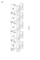
ここで図5を見ると、本開示の教示は、カートリッジヒータにしてもよい複数の個別のヒータ100,102,104,106,108に適用されてもよく、これらは、示されるように順番に接続される。各ヒータは、示されるように、抵抗加熱要素への異なる電源ピンの第1及び第2のジャンクションを備え、従って、各ヒータ100,102,104,106,108の平均温度は、上記のようにコントローラ70により判断することができる。別の形態では、ヒータ100,102,104,106,108のそれぞれは、自身の電力供給ピンを有し、この複数のヒータの実施形態の複雑さを軽減するために、単一の電力戻りピンがすべてのヒータに接続される。カートリッジヒータを備えたこの形式では、各コアには、各連続するヒータの電力供給ピンを収容するための通路が含まれてもよい。
Turning now to FIG. 5, the teachings of the present disclosure may be applied to a plurality of
ここで、図6及び7を参照すると、抵抗加熱要素110のピッチは、ヒータ120に沿って調整された熱プロファイルを提供するために、本開示の別の形態に従って変えることができる。一形態(図5)では、抵抗加熱要素110は、その長さに沿って連続的に可変のピッチを定める。より具体的には、抵抗加熱要素110は、直接隣接する次の360度コイルループ上で増加又は減少するピッチP4-P9に適応する能力を備えた連続可変ピッチを有する。抵抗加熱要素110の連続可変ピッチは、ヒータ表面(例えば、シース112の表面)の流束密度の徐々の変化を提供する。この連続可変ピッチの原理は、絶縁材114が充填された管状ヒータに適用されるものとして示されているが、原理は、上記のカートリッジヒータを含むがこれに限定されない任意のタイプのヒータにも適用してよい。さらに、上記のように、第1の電源ピン122は、第1の導電材で作られており、第2の電源ピン124は、第1の電源ピン122の第1の導電材と異なる第2の導電材で作られており、一方、抵抗加熱要素110は、ヒータ120の平均温度を判断するために、第1及び第2のジャンクション126,128での電圧の変化が検出されるように、第1及び第2の電源ピン122,124の第1及び第2の導電材と異なる材料で作られている。
Referring now to FIGS. 6 and 7, the pitch of
別の形態(図7)では、抵抗加熱要素130は、ゾーンA,B,CにそれぞれピッチP1,P2,P3を有する。P3は、P1より大きく、P1は、P2より大きい。抵抗加熱要素130は、示されるように、各ゾーンの長さに沿って一定のピッチを有する。同様に、第1の電源ピン132は、第1の導電材で作られており、第2の電源ピン134は、第1の電源ピン132の第1の導電材と異なる第2の導電材で作られており、一方、抵抗加熱要素130は、ヒータ120の平均温度を判断するために、第1及び第2のジャンクション136,138での電圧の変化が検出されるように、第1及び第2の電源ピン132,134の第1及び第2の導電材と異なる材料で作られている。
In another form (FIG. 7), the
図8を参照して、ここに記載されるヒータ及び二重目的電源ピンは、例として熱交換器140を含む多数の用途を有する。熱交換器140は、1又は複数の加熱要素142を含めてもよく、加熱要素142のそれぞれは、本開示の範囲内に留まりながら、上記で図示及び説明したようなゾーン又は可変ピッチ抵抗加熱要素をさらに含めてもよい。熱交換器の適用は単なる例示であり、本開示の教示は、その温度が無条件であろうと、上述したように水分の存在などの別の環境条件であろうと、温度測定も必要としながら、熱が与えられる任意の用途に用いることができることを理解されたい。
Referring to FIG. 8, the heater and dual purpose power pins described herein have a number of applications including, by way of example,
図9に示すように、本開示の教示は、層状ヒータ150などの他のタイプのヒータに適用してもよい。通常、層状ヒータ150は、基板154に適用される誘電体層152、誘電体層152に適用される抵抗加熱層156、及び、抵抗加熱層156を覆うように適用される保護層158を含む。ジャンクション160は、トレース抵抗層158の1つの端部と第1のリード線162との間に形成され(明確にするために1つの端部のみが示されている)、同様に、第2のジャンクションがもう1つの端部で形成され、上述したように本開示の原理に続いて、ヒータ150の平均温度を判断するために、これらのジャンクションでの電圧変化が検出される。そのような層状ヒータは、本出願と共に本発明の譲受人に譲渡され、その内容は参照によりその全体がここに組み込まれる米国特許第8,680,443号にさらに詳細に図示及び説明される。
The teachings of the present disclosure may be applied to other types of heaters, such as
本開示の教示によれば、上述したようなカートリッジ、管状、及び、層状のヒータではなく、又は、それに加えて、他のタイプのヒータも用いてもよい。これらの追加のタイプのヒータは、例えば、ポリマヒータ、フレキシブルヒータ、ヒートトレース、及び、セラミックヒータを含めてもよい。これらのタイプのヒータは単なる例示であり、本開示の範囲を限定するものとして解釈されるべきではないことを理解されたい。 Other types of heaters may also be used in accordance with the teachings of the present disclosure, instead of or in addition to cartridge, tubular, and laminar heaters as described above. These additional types of heaters may include, for example, polymer heaters, flexible heaters, heat tracing, and ceramic heaters. It is to be understood that these types of heaters are merely exemplary and should not be construed as limiting the scope of this disclosure.
ここで図10を参照すると、本開示の教示に従って少なくとも1つのヒータを制御する方法が示される。この方法は、以下のステップを含む。 Referring now to FIG. 10, a method of controlling at least one heater in accordance with the teachings of the present disclosure is illustrated. The method includes the following steps.
(A)第1の導電材で作られた電力供給ピンであり、電力供給ピンに電力を供給し、第1の導電材と異なる導電材で作られた電力戻りピンであり、電力戻りピンを通して電力を戻す加熱モードを作動させる。 (A) a power supply pin made of a first conductive material for supplying power to the power supply pin; and a power return pin made of a conductive material different from the first conductive material for supplying power to the power return pin; Activates heating mode which returns power.
(B)電力供給ピンに電力を供給し、2つの端部を有し、電力供給及び戻りピンの第1及び第2の導電材と異なる材料で作られた抵抗加熱要素に電力を供給し、抵抗加熱要素は、一方の端部で電力供給ピンと第1のジャンクションを、もう一方の端部で電力戻りピンと第2のジャンクションを形成し、さらに、電力戻りピンを通して電力を供給する。 (B) powering a power supply pin and powering a resistive heating element having two ends and made of a material different from the first and second conductive materials of the power supply and return pin; The resistive heating element forms a first junction with the power supply pin at one end and a second junction with the power return pin at the other end, and also provides power through the power return pin.
(C)ヒータの平均温度を判断するために、第1及び第2のジャンクションで電圧の変化を測定する。 (C) Measure the change in voltage at the first and second junctions to determine the average temperature of the heater.
(D)ステップ(C)で判断された平均温度に基づいて、必要に応じてヒータに供給される電力を調整する。 (D) Based on the average temperature determined in step (C), adjust the power supplied to the heater as necessary.
(E)ステップ(A)から(D)を繰り返す。 (E) Repeat steps (A) to (D).
この方法の別の形態では、破線で示されるように、コントローラが電圧の変化を測定するための測定モードに切り替える間、ステップ(B)が中断され、次にコントローラは加熱モードに切り替え戻す。 In another form of the method, step (B) is interrupted while the controller switches to a measurement mode for measuring the change in voltage, and then the controller switches back to the heating mode, as indicated by the dashed line.
本開示のさらに別の形態が、図11-13に示され、流動浸漬加熱で使用するためのヒータが図示され、通常、参照番号200で示される。ヒータ200は、流体に浸漬するために構成された加熱部202を備え、加熱部202は、複数の抵抗加熱要素204、及び、加熱部202に隣接する少なくとも2つの非加熱部206,208を備える(図11では、1つの非加熱部206のみを示す)。各非加熱部206,208は、長さを定め、複数の加熱要素204に電気的に接続された対応する複数のセットの電源ピンを備える。より具体的には、電源ピンの各セットは、第1の導電材で作られた第1の電源ピン212、及び、第1の電源ピン212の第1の導電材と異なる第2の導電材で作られた第2の電源ピン214を備える。第1の電源ピン212は、ジャンクション220,230,240を形成するように、非加熱部206,208内で第2の電源ピン214に電気的に接続される。さらに示すように、第2の電源ピン214は、加熱部202内に延びており、対応する抵抗加熱要素204に電気的に接続される。さらに、第2の電源ピン214は、第2の電源ピン214と抵抗加熱要素204との間の接続で、別のジャンクション又は測定可能な量の熱を生成しないように、対応する抵抗加熱要素204よりも大きい断面積を定める。
Yet another form of the present disclosure is illustrated in FIGS. 11-13, which depict a heater for use in fluidized immersion heating, generally designated by the
さらに示すように、終端部250は、非加熱部206と隣接しており、複数の第1の電源ピン212は、非加熱部206を出て、リード線及びコントローラ(図示せず)への電気接続のために終端部250内に延びる。前の説明と同様に、抵抗加熱要素204のそれぞれは、第1及び第2の電源ピン212,214の第1及び第2の導電材と異なる材料で作られており、第2の電源ピン214への第1の電源ピン212のジャンクション220,230,240のそれぞれは、非加熱部206,208の長さに沿った異なる位置に配置される。より具体的には、例として、ジャンクション220は距離L1にあり、ジャンクション230は距離L2にあり、ジャンクション240は距離L3にある。
As further shown, the
図13に示すように、時間「t」に渡るジャンクション220,230,240の温度で、ジャンクション220は流体Fに沈められ、ジャンクション230は流体に沈められるが深くなく、ジャンクション240は沈められない。従って、ジャンクション220,230,240のそれぞれで電圧の変化を検出することで、加熱部202に対する流体レベルの指標を提供することができる。特に、調理/フライヤー用途において流体が油である場合、火災を起こさないように、作業中に加熱部202が空気にさらされないことが望ましい。本開示の教示に従うジャンクション220,230,240を用いて、コントローラは、流体レベルが加熱部202に近すぎているかどうかを判断し、したがって、ヒータ200から電源を切ることができる。
As shown in FIG. 13, at the temperatures of
この例では、3つのジャンクション220,230,240が図示されているが、加熱部202内にジャンクションがないという条件で、本開示の範囲内に留まりながら、任意の数のジャンクションを採用してもよいことを理解されたい。
Although three
ここで、図14を参照すると、本開示のさらに別の形態は、示すように、ヒータシステム270のゾーンに配置された複数のヒータコア300を含む。この例示的な形態のヒータコア300は、上述のようにカートリッジヒータであるが、ここに記載の他のタイプのヒータも採用してもよいことを理解されたい。したがって、本開示のこの形態におけるカートリッジヒータ構造は、本開示の範囲を限定するものとして解釈されるべきではない。
Referring now to FIG. 14, yet another form of the present disclosure includes a plurality of
各ヒータコア300は、示すように、複数の電源ピン301,302,303,304,305を含む。上述した形態と同様に、電源ピンは、異なる導電材で作られており、より具体的には、電源ピン301,304,305は、第1の導電材で作られており、電源ピン302,303,306は、第1の導電材と異なる第2の導電材で作られている。さらに示すように、少なくとも1つのジャンパ320は、ジャンパ320の位置に近い温度測定値を得るために、異なる電源ピン、この例では、電源ピン301及び電源ピン303、の間に接続される。ジャンパ320は、例えば、ジャンパ320の位置に近接する温度を示すミリボルト信号を得るために充分なリード線又は他の導電部材でもよく、これは、上記で図示及び説明したようなコントローラ70と通信もする。異なる電源ピン間で任意の数のジャンパ320を使用してもよく、もう1つの位置は、ゾーン3とゾーン4の間で、電源ピン303と電源ピン305の間のジャンパ322で図示されている。
Each
この例示的な形態では、電源ピン301,303,305は、それぞれ、隣接する電源ピン302,304,306の間のヒータ回路の中性レッグである。より具体的には、ゾーン1のヒータ回路は、電源ピン301と302の間にあり、これらの電源ピンの間に抵抗加熱要素(例えば、図1に示す要素22)を備える。ゾーン2のヒータ回路は、電源ピン303と304の間にあり、これら2つの電源ピンの間に抵抗加熱要素を備える。同様に、ゾーン3のヒータ回路は、電源ピン305と306の間にあり、これら2つの電源ピンの間に抵抗加熱要素を備える。これらのヒータ回路は、単なる例示であり、図1を参照して上述したカートリッジヒータの教示に従って構成されることを理解されたい。
In this exemplary form, power pins 301, 303, 305 are the neutral leg of the heater circuit between adjacent power pins 302, 304, 306, respectively. More specifically, the
ここで、図15を参照すると、一形態では、ヒータ400は、温度を測定するためにヒータ400内又はヒータ400の外側に配置することができる主センシングジャンクションを含むように構成される。ヒータ400は、抵抗加熱要素402、第1の電源ピン404、及び、第2の電源ピン406を含む。抵抗加熱要素402は、第1の端部及び第2の端部を有する。第1の電源ピン404は、第1のジャンクション408を形成するように、抵抗加熱要素402の第1の端部に接続され、第2の電源ピン406は、第2のジャンクション410を形成するように、抵抗加熱要素402の第2の端部に接続される。第1の電源ピン404及び第2の電源ピン406は、コントローラを介して加熱要素402に電力を供給する機能をする。
Referring now to FIG. 15, in one form,
第2の電源ピン406は、第1のリード線412及び第2のリード線414を含む。第1のリード線412は、第2のジャンクション410を形成するように、抵抗加熱要素402の第2の端部に接続され、第2のリード線414は、第1の基準エリアで、主センシングジャンクション416を形成するように、第1のリード線412に接続される。第2のリード線414は、第1のリード線412を介して抵抗加熱要素402をコントローラに接続するように構成される。
一形態では、第1のリード線412及び第2のリード線414は、非類似の導電材、又は、より具体的には、異なるゼーベック係数を有する材料で作られている。例えば、ニッケル合金、鉄、コンスタンタン、又は、アルメル(登録商標)などの様々な組合せを使用してもよい。第1のリード線412と第2のリード線414の材料の違いは、図15の異なるスタイルの線により表されている(例えば、第2のリード線414については破線、第1のリード線412については一点鎖線)。材料が異なるので、主センシングジャンクション416は、事実上、第1の基準エリアでの温度を判断するために測定される電圧変化を生成するための熱電対である。従って、この形態では、抵抗加熱要素402に接続するためのジャンクション408及び410は、センシング位置から分離されている。従って、ヒータ400は、加熱要素402の端部での温度を検出することに限定されず、温度測定は、ヒータ400内の様々な位置で検出されてもよい。さらに、一形態では、第1のリード線412及び第2のリード線414は、ヒータ400の外側に主センシングジャンクション416を有するように構成される。
In one form, the
図2について論じたように、コントローラ(図15に示さず)は、第1の電源ピン404及び第2の電源ピン406と通信し、電源ピン404及び406を介して抵抗加熱要素402に電力を供給するように構成される。コントローラは、材料のゼーベック係数を利用して、センシングジャンクション416により生成された電圧変化に基づいて、第1の基準エリアでの温度を演算するようにも構成される。
As discussed with respect to FIG. 2, a controller (not shown in FIG. 15) communicates with a
一形態では、抵抗加熱要素402、第1の電源ピン404、及び、第2の電源ピン406の第1のリード線412は、同じ導電材又は類似のゼーベック特性(即ち、実質的に同じゼーベック係数)を有する材料で作られている。従って、第1のジャンクション408及び第2のジャンクション410により生成される電圧変化は実質的にゼロであり、コントローラにより判断される温度測定は、主センシングジャンクション416により生成される電圧変化に基づく。
In one form, the first leads 412 of the
別の形態では、抵抗加熱要素402、第1の電源ピン404、及び/又は、第2の電源ピン406の第1のリード線412は、異なる導電材で作られている。そのような構成では、第2のリード線414の材料は、第2のリード線414のゼーベック係数が、抵抗加熱要素402、第1の電源ピン404、及び、第2の電源ピン406の第1のリード線412のものと最も異なるように選択される。従って、主センシングジャンクション416は、全体的な温度測定に最大の貢献をするものとして提供され、第1及び第2のジャンクション408及び410からの任意の温度測定は最小限になる。
In another form, the
上記で論じたように、温度は、電力信号のゼロ交差で検出することができる。或いは、コントローラは、抵抗加熱要素に電源を向けるための加熱モードと、基準エリアでの温度を判断するために主センシングジャンクション416での電圧の変化を測定するための測定モードとを切り替えるように構成される。
As discussed above, temperature can be detected at zero crossings of the power signal. Alternatively, the controller is configured to switch between a heating mode for directing power to the resistive heating element and a measurement mode for measuring changes in voltage at the
図16を参照すると、一形態では、ヒータ420は、2つのセンシングジャンクションの間の仮想点で温度を検出するために、互いに近接した2つのセンシングジャンクションを含む。ここで、ヒータ420は、抵抗加熱要素422、第2の電源ピン424、及び、第1の電源ピン426を備える。抵抗加熱要素422は、第1の端部及び第2の端部を含む。第1の電源ピン426は、加熱要素422の第1の端部と第1のジャンクション428を形成し、第2の電源ピン424は、加熱要素422の第2の端部と第2のジャンクション430を形成する。第2の電源ピン424は、図15の第2の電源ピン406と同様の方法で構成され、従って、第2のジャンクション430を形成するように抵抗加熱要素422に接続される第1のリード線432、及び、ヒータ420内の第1の基準エリアで第1の主センシングジャンクション440を形成するように第1のリード線432に接続される第2のリード線434を含む。
Referring to FIG. 16, in one form,
この形態では、第1の電源ピン426は、第2の電源ピン424と同様の方法で構成され、センシングジャンクションを形成するように、2つのリード線(即ち、第3のリード線436及び第4のリード線438)を備える。より具体的には、第3のリード線436は、第1のジャンクション428を形成するように、抵抗加熱要素422の第1の端部に接続され、第4のリード線438は、第2の基準エリアで第3のリード線436と第2の主センシングジャンクション422を形成する。第2の主センシングジャンクション422は、第1の主センシングジャンクション440を有する第1の基準エリアに隣接して近接するヒータ420の第2の基準エリアに提供される。センシングジャンクション440及び442は、ヒータ420内として備えるが、センシングジャンクション440及び442は、ヒータ420の外側に備えることもできる。
In this configuration, the
第2の電源ピン424と同様に、第3のリード線436は、第4のリード線438のものと異なる導電材で作られており、第2の電源ピン424の第2のリード線434のものと異なる導電材でできている。したがって、第2の主センシングジャンクション442は、第1及び第2の基準エリア間の温度を判断するために第1の主センシングジャンクションと共同で使用される事実上の熱電対である。さらに、第1のジャンクション428及び第2のジャンクション430により生成される電圧変化が実質的にゼロであり、コントローラにより判断される温度測定がセンシングジャンクション440及び442での電圧変化に基づくように、抵抗加熱要素422、第2の電源ピン424の第1のリード線432、第1の電源ピン426の第3のリード線436は、同じ導電材又は類似のゼーベック特性を有する材料で作られている。
Like the
コントローラ(図16に示さず)は、第1の電源ピン426及び第2の電源ピン424を介して加熱要素422に電力を供給し、ジャンクション440及び442により生成された電圧変化に基づいて、2つのセンシングジャンクション440及び442の間の仮想点で温度を測定するように構成される。一形態では、第1及び第2の基準エリアでの温度は、実質的に同じであると推定され、従って、コントローラにより検出される温度は、第1及び第2の基準エリアの間の仮想点に関連付けられる。
A controller (not shown in FIG. 16) provides power to the
図17A及び図17Bを参照すると、一形態では、主センシングジャンクションは、ヒータの外側の仮想点で又はヒータ内の基準エリアで温度を測定するためにカートリッジヒータに備えられる。図17Aは、金属線の形態の抵抗加熱要素452、第1の電源ピン454、及び、第2の電源ピン456を含むカートリッジヒータ450を図示している。カートリッジヒータ450は、2つのセンシングジャンクションの間の仮想点で温度を測定するために、ヒータ450の外側に備えられた2つのセンシングジャンクションを含むように構成される。
Referring to FIGS. 17A and 17B, in one form, a primary sensing junction is provided in the cartridge heater to measure temperature at a virtual point outside the heater or at a reference area within the heater. FIG. 17A illustrates a
より具体的には、一形態では、抵抗加熱要素452は、図1に関して論じたように、非導電部(又は、この形態のコア)の周りに巻かれるか、又は、配置される。第1の電源ピン454は、第1のリード線458及び第2のリード線460を備える。第1のリード線458は、第1のジャンクション462を形成するように、抵抗加熱要素452の第1の端部に接続され、第2のリード線460は、ヒータ450の外側の第1の基準エリアに、第1のリード線458と第1の主センシングジャンクション464を形成する。第2の電源ピン456は、第3のリード線466及び第4のリード線468を備える。第3のリード線466は、第2のジャンクション470を形成するように、抵抗加熱要素452に接続される。第4のリード線468は、ヒータ450の外側の第2の基準エリアに第2の主センシングジャンクション472を形成するように、第3のリード線466に接続される。第1及び第2の主センシングジャンクション464及び472は、互いに隣接して近接して配置されている。
More specifically, in one form, the
一形態では、抵抗加熱要素452、第1の電源ピン454の第1のリード線458、及び、第2の電源ピン456の第3のリード線466は、同じ材料又は類似のゼーベック特性を有する材料で作られており、第1の電源ピン454の第2のリード線460及び第2の電源ピン456の第4のリード線468の材料と異なる。また、第1の電源ピン454の第2のリード線460の材料は、第2の電源ピン456の第4のリード線468の材料と異なる。従って、第1及び第2の主ジャンクション464及び472は、2つのジャンクション464及び472の間の仮想点の温度を検出するように、熱電対として機能する。
In one form, the
図17Bは、ヒータ内に配置された1つの主ジャンクションを有するカートリッジヒータ480を図示している。カートリッジヒータ480は、2つの端部、第1の電源ピン484、及び、第2の電源ピン486を有する抵抗加熱要素482を含む。第1の電源ピン484は、加熱要素482の第1の端部と第1のジャンクション488を形成し、第2の電源ピン486は、加熱要素482の第2の端部と第2のジャンクション490を形成する。図15のヒータと同様に、第2の電源ピン486は、異なる材料で作られている(即ち、異なるゼーベック係数を有する)第1のリード線492及び第2のリード線494を含む。第1のリード線492は、第2のジャンクション490を形成するように、抵抗加熱要素482の第2の端部に接続され、第2のリード線494は、ヒータ480内の第1の基準エリアに主センシングジャンクション496を形成するように、第1のリード線492に接続される。従って、主センシングジャンクション490は、第1の基準エリアの温度を測定するための熱電対として機能する。
FIG. 17B illustrates a
一形態では、抵抗加熱要素482、第1の電源ピン484、及び、第2の電源ピン486の第1のリード線492は、同じ導電材又は類似のゼーベック特性を有する材料で作られている。従って、第1のジャンクション488及び第2のジャンクション490により生成される電圧変化は、実質的にゼロであり、コントローラにより判断される温度測定は、主センシングジャンクション490により生成される電圧変化に基づいている。
In one form, the
図18を参照すると、本開示の主センシングジャンクションは、ヒータの内面とヒータの外面の間の温度を推定するために、熱流束センサの一部として使用されてもよい。より具体的には、一形態では、ヒータ500は、管を通り抜けて続く流体(例えば、ガス)を加熱するように機能し、抵抗加熱(即ち、熱)要素502(極めて細い線で示される)、第1の電源ピン504、及び、第2の電源ピン506を備える。図18には完全には図示されていないが、抵抗加熱要素502は、ヒータ500を貫通するように構成され、カバーにより保護される。第1の電源ピン504及び第2の電源ピン506は、それぞれ、加熱要素502の第1の端部と第1のジャンクションを、及び、加熱要素502の第2の端部との第2のジャンクションを形成するように、ヒータ500のカバー内に延びている。
Referring to FIG. 18, the main sensing junction of the present disclosure may be used as part of a heat flux sensor to estimate the temperature between the inner surface of the heater and the outer surface of the heater. More specifically, in one form, the
抵抗加熱要素502は、それがヒータとして、かつ、温度センサとして機能するような「2線の」加熱要素である。そのような2線の機能は、例えば、本出願と共に本発明の譲受人に譲渡され、参照によりその全体がここに組み込まれる米国特許第7,196,295号に開示されている。通常、2線のシステムの場合、加熱要素502は、高い抵抗温度係数(TCR)の材料で作られている。コントローラ(図18に示せず)は、第1及び第2の電源ピン504及び506と通信し、電源ピン504及び506の間の電圧(即ち、mV)変化を測定するように構成される。電圧変化を利用して、コントローラは、抵抗加熱要素502(例えば、R1の周り)の平均温度を演算する。
第1の電源ピン504は、異なる材料で作られている(即ち、異なるゼーベック係数を有する)第1のリード線508及び第2のリード線510を含む。第1のリード線508は、加熱要素502と第2のジャンクションを形成し、第2のリード線510は、ヒータ500の外面(即ち、R2)に沿った(即ち、加熱要素502のものとは異なる面に沿った)第2の基準エリアで第1のリード線508と主センシングジャンクション512を形成する。従って、主センシングジャンクション512は、センシングジャンクション512により生成された電圧変化に基づいて、第2の基準エリアの温度を測定するための熱電対として機能する。抵抗加熱要素502、第2の電源ピン506、及び、第1の電源ピン504の第1のリード線508は、同じ材料で作られているか、又は、類似のゼーベック特性を有する材料で作られている。
The
一形態では、コントローラは、加熱要素502の温度測定、主センシングジャンクション512の温度、及び、コントローラからヒータ500に供給される電力に基づいて、ヒータ500の内面(即ち、第1の基準エリア)と外面(第2の基準エリア)の間の仮想点での温度を推定するように構成される。より具体的には、コントローラは、2線のシステムに関して説明したように、電源ピン506及び504の間の電圧変化を利用して、第1の基準エリアでの加熱要素の平均温度を判断する。コントローラは、主センシングジャンクション512により生成された電圧変化、及び、第1及び第2のリード線508及び510のゼーベック係数に基づいて、第2の基準エリアの温度をさらに判断する。2つの測定結果、供給される電力、及び、ヒータの形状を用いて、コントローラは、ヒータ500内の所望の位置(例えば、ヒータ内の任意の位置)の第3の基準エリアでの温度を演算することができる。さらに、ヒータ500の形状が既知である場合、コントローラは、ヒータ500の内面と外面の間の熱流束を判断するように構成することもできる。熱流束は、例えば、冷たい流体の入口エリアを検出し、温度設定値を調整し、及び/又は、他の適切なシステム制御機器に使用することができる。ヒータ500は、管として図示されているが、ヒータは、他の適切な形状(例えば、平板)で構成されてもよく、それでも本開示の範囲内である。
In one form, the controller determines whether the inner surface of the heater 500 (i.e., the first reference area) and It is configured to estimate the temperature at a virtual point between the outer surfaces (second reference area). More specifically, the controller utilizes the voltage change between power pins 506 and 504 to determine the average temperature of the heating element in the first reference area, as described for the two-wire system. The controller further determines the temperature of the second reference area based on the voltage change produced by the
さらに、一形態では、ヒータ500が通電される前、ヒータ500は、実質的に室温にあり、主センシングジャンクション512は、高TCR要素線(即ち、加熱要素502)と同じ又は実質的に同じ温度になる。コントローラは、主センシングジャンクション512を使用して温度を測定し、さらに加熱要素502の抵抗を測定するように構成される。コントローラは、ヒータ500の抵抗を主センシングジャンクション512により測定された温度と関連付け、他の抵抗を温度に変換するために、このベースライン値を使用し、それにより加熱要素502を調整する。
Further, in one form, before
図19を参照すると、主センシングジャンクションは、表面に沿った温度測定を改善するために様々な適切な方法で構成することができる。例えば、一形態では、主センシングジャンクション550は、異なる材料で作られた第1のリード線552及び第2のリード線554により形成される。センシングジャンクション550は、平面形状(即ち、平ら)を有しており、表面との熱接触を改善し、加熱要素から来る熱を拡散するために、熱伝導材(例えば、銅)である熱ディフューザ556により囲まれている。
Referring to FIG. 19, the main sensing junction can be configured in a variety of suitable ways to improve temperature measurement along the surface. For example, in one form, the
本開示の主センシングジャンクションは、熱電対として機能して、ヒータ内及びヒータの外側でさえ異なる位置での温度測定を可能にする。従って、温度測定は、加熱要素の端部に限定されない。さらに、ヒータは、別個の温度センサを必要としないため、ヒータの複雑さが軽減される。 The primary sensing junction of the present disclosure functions as a thermocouple to enable temperature measurements at different locations within the heater and even outside the heater. Therefore, temperature measurements are not limited to the ends of the heating element. Additionally, the heater does not require a separate temperature sensor, reducing the complexity of the heater.
本開示は、例として説明及び図示された実施形態に限定されないことに留意されたい。多種多様な改良が説明されており、それよりも多くが、当業者の知識の一部である。本開示及び本特許の保護の範囲を離れることなく、これら及びさらなる改良並びに技術的同等物による任意の置換を説明及び図面に追加することができる。
以下に、本願の当初の特許請求の範囲に記載された発明を付記する。
[1]
ヒータであって、
抵抗加熱要素と、
前記抵抗加熱要素の第1の端部と第1のジャンクションを形成する第1の電源ピンと、
第2の電源ピンとを備え、前記第2の電源ピンは、
前記抵抗加熱要素の第2の端部と第2のジャンクションを形成し、第1の導電材を定める第1のリード線と、
第1の基準エリアで前記第1のリード線と主センシングジャンクションを形成する第2のリード線とを備え、前記第2のリード線は、前記主センシングジャンクションにより生成される電圧変化に基づいて、前記第1の基準エリアの温度を測定するために、前記第1の導電材と異なる第2の導電材を定める。
[2]
前記第1の電源ピン、前記第2の電源ピンの前記第1のリード線、及び、前記抵抗加熱要素は、同じ材料で作られている、[1]に記載のヒータ。
[3]
前記第1の電源ピン、及び、前記第2の電源ピンの前記第1のリード線は、同じ材料で作られている、[1]に記載のヒータ。
[4]
前記第1の電源ピン及び前記第2の電源ピンと通信するコントローラをさらに備え、前記コントローラは、前記抵抗加熱要素に電源を向けるための加熱モードと、前記第1の基準エリアの温度を判断するために前記主センシングジャンクションにより生成される電圧変化を測定するための測定モードとを切り替えるように構成される、[1]に記載のヒータ。
[5]
前記コントローラは、前記主センシングジャンクションにより測定された温度を使用して前記抵抗加熱要素を調整するように構成される、[4]に記載のヒータ。
[6]
前記抵抗加熱要素は、前記抵抗加熱要素に沿った第2の基準エリアの温度を検知するように機能し、前記コントローラは、前記第2の基準エリアの温度を判断するように、前記抵抗加熱要素の抵抗を測定する、[4]に記載のヒータ。
[7]
前記コントローラは、前記第1の基準エリア及び前記第2の基準エリアの温度、前記ヒータの形状、並びに、ヒータ要素に供給される電力に基づいて、第3の基準エリアの温度を演算するように構成される、[6]に記載のヒータ。
[8]
前記第1及び第2の電源ピンと通信し、前記抵抗加熱要素への電力を遮断せずに前記第1及び第2のジャンクションの電圧の変化を測定するように構成されたコントローラをさらに備える、[1]に記載のヒータ。
[9]
前記第1の電源ピン、前記第2の電源ピンの前記第1のリード線、及び、前記抵抗加熱要素のゼーベック係数は、実質的に同じである、[1]に記載のヒータ。
[10]
前記主センシングジャンクションは、前記抵抗加熱要素の前記第1の端部と前記第2の端部の間の前記抵抗加熱要素に沿って配置される、[1]に記載のヒータ。
[11]
前記主センシングジャンクションは、前記ヒータの外側に配置される、[1]に記載のヒータ。
[12]
前記第1の電源ピンは、
前記第1のジャンクションを形成するように前記抵抗加熱要素の前記第1の端部に接続される第3のリード線であり、前記第1の導電材を定める前記第3のリード線と、
前記第1の基準エリアに隣接して近接する第2の基準エリアで前記第3のリード線と第2の主センシングジャンクションを形成する第4のリード線であり、前記第1及び第2の基準エリア間の温度を判断するために前記主センシングジャンクションと共同で使用され、熱電対として機能するために、前記第1の導電材及び前記第2の導電材と異なる第3の導電材を定める前記第4のリード線とを備える、[1]に記載のヒータ。
[13]
前記第2の電源ピンの前記第1のリード線、前記第1の電源ピンの前記第3のリード線、及び、前記抵抗加熱要素のゼーベック係数は、実質的に同じである、[9]に記載のヒータ。
[14]
前記主センシングジャンクションの周りに配置された熱ディフューザをさらに備える、[1]に記載のヒータ。
[15]
近位端部及び遠位端部を定める非導電部であり、前記非導電部は、少なくとも前記近位端部を貫通する第1及び第2の開口を有し、前記第1及び第2の電源ピンは、前記第1及び第2の開口内に配置され、周囲に前記抵抗加熱要素が配置された前記非導電部と、
前記非導電部を取り囲むシースと
前記非導電部の前記近位端部部分に配置され、少なくとも部分的に前記シース内に延びるシーリング部材とをさらに備える、[1]に記載のヒータ。
It is noted that the present disclosure is not limited to the embodiments described and illustrated by way of example. A wide variety of modifications have been described and many more are part of the knowledge of those skilled in the art. These and further improvements and any substitutions by technical equivalents may be added to the description and drawings without departing from the scope of the disclosure and protection of this patent.
Below, the invention described in the original claims of the present application will be added.
[1]
A heater,
a resistive heating element;
a first power pin forming a first junction with a first end of the resistive heating element;
a second power supply pin, the second power supply pin comprising:
a first lead forming a second junction with a second end of the resistive heating element and defining a first electrically conductive material;
a second lead forming a main sensing junction with the first lead in a first reference area, wherein the second lead is configured to: In order to measure the temperature of the first reference area, a second conductive material different from the first conductive material is defined.
[2]
The heater according to [1], wherein the first power pin, the first lead wire of the second power pin, and the resistance heating element are made of the same material.
[3]
The heater according to [1], wherein the first lead wire of the first power pin and the second lead wire of the second power pin are made of the same material.
[4]
further comprising a controller in communication with the first power pin and the second power pin, the controller for determining a heating mode for directing power to the resistive heating element and a temperature of the first reference area. The heater according to [1], wherein the heater is configured to switch between a measurement mode for measuring a voltage change generated by the main sensing junction and a measurement mode for measuring a voltage change generated by the main sensing junction.
[5]
The heater of [4], wherein the controller is configured to adjust the resistive heating element using the temperature measured by the main sensing junction.
[6]
The resistive heating element is operative to sense a temperature of a second reference area along the resistive heating element, and the controller is configured to operate the resistive heating element to determine a temperature of the second reference area. The heater according to [4], which measures the resistance of the heater.
[7]
The controller calculates the temperature of the third reference area based on the temperatures of the first reference area and the second reference area, the shape of the heater, and the electric power supplied to the heater element. The heater according to [6], comprising:
[8]
further comprising a controller in communication with the first and second power pins and configured to measure changes in voltage at the first and second junctions without interrupting power to the resistive heating element; 1].
[9]
The heater according to [1], wherein the Seebeck coefficients of the first power pin, the first lead wire of the second power pin, and the resistive heating element are substantially the same.
[10]
The heater according to [1], wherein the main sensing junction is located along the resistive heating element between the first end and the second end of the resistive heating element.
[11]
The heater according to [1], wherein the main sensing junction is arranged outside the heater.
[12]
The first power pin is
a third lead connected to the first end of the resistive heating element to form the first junction and define the first electrically conductive material;
a fourth lead forming a second main sensing junction with the third lead in a second reference area adjacent and proximate to the first reference area, the fourth lead forming a second main sensing junction with the third lead; a third electrically conductive material different from the first electrically conductive material and the second electrically conductive material for use in conjunction with the main sensing junction to determine the temperature between the areas and to function as a thermocouple; The heater according to [1], comprising a fourth lead wire.
[13]
According to [9], the Seebeck coefficients of the first lead of the second power pin, the third lead of the first power pin, and the resistive heating element are substantially the same. Heater listed.
[14]
The heater according to [1], further comprising a heat diffuser disposed around the main sensing junction.
[15]
a non-conductive portion defining a proximal end and a distal end, the non-conductive portion having first and second openings passing through at least the proximal end; a power pin is disposed within the first and second openings, and the non-conductive portion is surrounded by the resistive heating element;
a sheath surrounding the non-conductive part;
The heater according to [1], further comprising a sealing member disposed at the proximal end portion of the non-conductive portion and extending at least partially into the sheath.
Claims (15)
抵抗加熱要素と、
前記抵抗加熱要素の第1の端部と第1のジャンクションを形成する第1の電源ピンと、
第2の電源ピンとを備え、前記第2の電源ピンは、
前記抵抗加熱要素の第2の端部と第2のジャンクションを形成し、第1の導電材を定める第1のリード線と、
第1の基準エリアで前記第1のリード線と主センシングジャンクションを形成する第2のリード線とを備え、前記第2のリード線は、前記主センシングジャンクションにより生成される電圧変化に基づいて、前記第1の基準エリアの温度を測定するために、前記主センシングジャンクションが熱電対として機能するように、前記第1の導電材と異なる第2の導電材を定め、
前記主センシングジャンクションにより測定される温度は、前記ヒータの全体的な温度を表す。 A heater,
a resistive heating element;
a first power pin forming a first junction with a first end of the resistive heating element;
a second power supply pin, the second power supply pin comprising:
a first lead forming a second junction with a second end of the resistive heating element and defining a first electrically conductive material;
a second lead forming a main sensing junction with the first lead in a first reference area, wherein the second lead is configured to: defining a second electrically conductive material different from the first electrically conductive material such that the main sensing junction functions as a thermocouple to measure the temperature of the first reference area ;
The temperature measured by the main sensing junction represents the overall temperature of the heater .
前記第1のジャンクションを形成するように前記抵抗加熱要素の前記第1の端部に接続される第3のリード線であり、前記第1の導電材を定める前記第3のリード線と、
前記第1の基準エリアに隣接して近接する第2の基準エリアで前記第3のリード線と第2の主センシングジャンクションを形成する第4のリード線であり、前記第1及び第2の基準エリア間の温度を判断するために前記主センシングジャンクションと共同で使用され、熱電対として機能するために、前記第1の導電材及び前記第2の導電材と異なる第3の導電材を定める前記第4のリード線とを備える、請求項1に記載のヒータ。 The first power pin is
a third lead connected to the first end of the resistive heating element to form the first junction and define the first electrically conductive material;
a fourth lead forming a second main sensing junction with the third lead in a second reference area adjacent and proximate to the first reference area, the fourth lead forming a second main sensing junction with the third lead; a third electrically conductive material different from the first electrically conductive material and the second electrically conductive material for use in conjunction with the main sensing junction to determine the temperature between the areas and to function as a thermocouple; The heater according to claim 1, further comprising a fourth lead wire.
前記非導電部を取り囲むシースと
前記非導電部の前記近位端部部分に配置され、少なくとも部分的に前記シース内に延びるシーリング部材とをさらに備える、請求項1に記載のヒータ。 a non-conductive portion defining a proximal end and a distal end, the non-conductive portion having first and second openings passing through at least the proximal end; a power pin is disposed within the first and second openings, and the non-conductive portion is surrounded by the resistive heating element;
The heater of claim 1 , further comprising: a sheath surrounding the non-conductive portion; and a sealing member disposed at the proximal end portion of the non-conductive portion and extending at least partially into the sheath.
Applications Claiming Priority (3)
| Application Number | Priority Date | Filing Date | Title |
|---|---|---|---|
| US15/950,358 | 2018-04-11 | ||
| US15/950,358 US11096248B2 (en) | 2015-05-29 | 2018-04-11 | Resistive heater with temperature sensing power pins and auxiliary sensing junction |
| PCT/US2019/025106 WO2019199506A1 (en) | 2018-04-11 | 2019-04-01 | Resistive heater with temperature sensing power pins and auxiliary sensing junction |
Publications (3)
| Publication Number | Publication Date |
|---|---|
| JP2021521589A JP2021521589A (en) | 2021-08-26 |
| JPWO2019199506A5 JPWO2019199506A5 (en) | 2022-04-07 |
| JP7374922B2 true JP7374922B2 (en) | 2023-11-07 |
Family
ID=66175503
Family Applications (1)
| Application Number | Title | Priority Date | Filing Date |
|---|---|---|---|
| JP2020555520A Active JP7374922B2 (en) | 2018-04-11 | 2019-04-01 | Resistive heater with temperature sensing power pin and auxiliary sensing junction |
Country Status (6)
| Country | Link |
|---|---|
| EP (1) | EP3777476A1 (en) |
| JP (1) | JP7374922B2 (en) |
| KR (1) | KR20210007986A (en) |
| CN (1) | CN112042265B (en) |
| TW (1) | TWI741278B (en) |
| WO (1) | WO2019199506A1 (en) |
Families Citing this family (4)
| Publication number | Priority date | Publication date | Assignee | Title |
|---|---|---|---|---|
| US11540358B2 (en) | 2015-05-29 | 2022-12-27 | Watlow Electric Manufacturing Company | Modular heater assembly with interchangeable auxiliary sensing junctions |
| TWI809369B (en) * | 2020-04-06 | 2023-07-21 | 美商瓦特洛威電子製造公司 | Modular heater assembly with interchangeable auxiliary sensing junctions |
| CN116420924A (en) * | 2022-01-04 | 2023-07-14 | 深圳市合元科技有限公司 | Gas mist generating device and resistance heater for gas mist generating device |
| JP7113576B1 (en) * | 2022-04-08 | 2022-08-05 | 白光株式会社 | Heater sensor complex and iron tip cartridge |
Citations (2)
| Publication number | Priority date | Publication date | Assignee | Title |
|---|---|---|---|---|
| WO2016196055A1 (en) | 2015-05-29 | 2016-12-08 | Watlow Electric Manufacturing Company | Resistive heater with temperature sensing power pins |
| JP6060280B2 (en) | 2014-05-28 | 2017-01-11 | 白光株式会社 | Heater / sensor subassembly and solder cartridge |
Family Cites Families (8)
| Publication number | Priority date | Publication date | Assignee | Title |
|---|---|---|---|---|
| US2831951A (en) | 1954-07-06 | 1958-04-22 | Watlow Electric Mfg | Cartridge heater and method of making same |
| US3970822A (en) | 1975-03-17 | 1976-07-20 | Watlow Electric Manufacturing Company | Electric cartridge heater |
| FI107963B (en) * | 1995-06-20 | 2001-10-31 | Instrumentarium Oy | infrared Radiator |
| JP3124506B2 (en) * | 1997-03-14 | 2001-01-15 | 白光株式会社 | Heater / sensor complex |
| US7196295B2 (en) | 2003-11-21 | 2007-03-27 | Watlow Electric Manufacturing Company | Two-wire layered heater system |
| US8680443B2 (en) | 2004-01-06 | 2014-03-25 | Watlow Electric Manufacturing Company | Combined material layering technologies for electric heaters |
| US9786829B2 (en) * | 2010-03-19 | 2017-10-10 | Micropen Technologies Corporation | Thermocouple device |
| US9279731B2 (en) * | 2013-03-12 | 2016-03-08 | Lam Research Corporation | Multichannel thermocouple compensation for three dimensional temperature gradient |
-
2019
- 2019-04-01 KR KR1020207032550A patent/KR20210007986A/en not_active Application Discontinuation
- 2019-04-01 JP JP2020555520A patent/JP7374922B2/en active Active
- 2019-04-01 EP EP19717663.9A patent/EP3777476A1/en active Pending
- 2019-04-01 CN CN201980029161.4A patent/CN112042265B/en active Active
- 2019-04-01 WO PCT/US2019/025106 patent/WO2019199506A1/en unknown
- 2019-04-09 TW TW108112368A patent/TWI741278B/en active
Patent Citations (2)
| Publication number | Priority date | Publication date | Assignee | Title |
|---|---|---|---|---|
| JP6060280B2 (en) | 2014-05-28 | 2017-01-11 | 白光株式会社 | Heater / sensor subassembly and solder cartridge |
| WO2016196055A1 (en) | 2015-05-29 | 2016-12-08 | Watlow Electric Manufacturing Company | Resistive heater with temperature sensing power pins |
Also Published As
| Publication number | Publication date |
|---|---|
| CN112042265B (en) | 2023-06-20 |
| TWI741278B (en) | 2021-10-01 |
| EP3777476A1 (en) | 2021-02-17 |
| CN112042265A (en) | 2020-12-04 |
| KR20210007986A (en) | 2021-01-20 |
| JP2021521589A (en) | 2021-08-26 |
| TW201946491A (en) | 2019-12-01 |
| WO2019199506A1 (en) | 2019-10-17 |
Similar Documents
| Publication | Publication Date | Title |
|---|---|---|
| US11533782B2 (en) | Resistive heater with temperature sensing power pins | |
| JP7374922B2 (en) | Resistive heater with temperature sensing power pin and auxiliary sensing junction | |
| TWI690706B (en) | Sensor system and integrated heater-sensor for measuring and controlling performance of a heater system | |
| US11096248B2 (en) | Resistive heater with temperature sensing power pins and auxiliary sensing junction | |
| US20230134684A1 (en) | Modular heater assembly with interchangeable auxiliary sensing junctions | |
| TWI809369B (en) | Modular heater assembly with interchangeable auxiliary sensing junctions |
Legal Events
| Date | Code | Title | Description |
|---|---|---|---|
| A521 | Request for written amendment filed |
Free format text: JAPANESE INTERMEDIATE CODE: A523 Effective date: 20220330 |
|
| A621 | Written request for application examination |
Free format text: JAPANESE INTERMEDIATE CODE: A621 Effective date: 20220330 |
|
| A131 | Notification of reasons for refusal |
Free format text: JAPANESE INTERMEDIATE CODE: A131 Effective date: 20230214 |
|
| A601 | Written request for extension of time |
Free format text: JAPANESE INTERMEDIATE CODE: A601 Effective date: 20230510 |
|
| A521 | Request for written amendment filed |
Free format text: JAPANESE INTERMEDIATE CODE: A523 Effective date: 20230713 |
|
| TRDD | Decision of grant or rejection written | ||
| A01 | Written decision to grant a patent or to grant a registration (utility model) |
Free format text: JAPANESE INTERMEDIATE CODE: A01 Effective date: 20231010 |
|
| A61 | First payment of annual fees (during grant procedure) |
Free format text: JAPANESE INTERMEDIATE CODE: A61 Effective date: 20231025 |
|
| R150 | Certificate of patent or registration of utility model |
Ref document number: 7374922 Country of ref document: JP Free format text: JAPANESE INTERMEDIATE CODE: R150 |