JP6711739B2 - Absorbent article - Google Patents
Absorbent article Download PDFInfo
- Publication number
- JP6711739B2 JP6711739B2 JP2016233557A JP2016233557A JP6711739B2 JP 6711739 B2 JP6711739 B2 JP 6711739B2 JP 2016233557 A JP2016233557 A JP 2016233557A JP 2016233557 A JP2016233557 A JP 2016233557A JP 6711739 B2 JP6711739 B2 JP 6711739B2
- Authority
- JP
- Japan
- Prior art keywords
- absorbent article
- elastic member
- region
- sheet
- width direction
- Prior art date
- Legal status (The legal status is an assumption and is not a legal conclusion. Google has not performed a legal analysis and makes no representation as to the accuracy of the status listed.)
- Active
Links
Images


Description
本発明は、肌面側に設けられたギャザーを備えた吸収性物品に関する。 The present invention relates to an absorbent article including gathers provided on the skin side.
近年、防漏ギャザー又は立体ギャザーを備えた使い捨て紙おむつのような吸収性物品が知られている(特許文献1及び特許文献2)。特許文献1に記載された吸収性物品は、使用状態において使用面側に自由起立する脚周り用バリヤーカフスを有する。バリヤーカフスは、バリヤーカフスの起立遠位縁近傍に接触用弾性伸縮部材を有し、バリヤーカフスの起立領域内の起立近位縁近傍に起立用弾性伸縮部材を有する。
In recent years, absorbent articles such as disposable paper diapers having leak-proof gathers or three-dimensional gathers are known (
特許文献2に記載の吸収性物品は、着用者の肌側に配される肌対向シート、肌側とは反対側に配される裏面シート、これらの間に配された吸収体4と、を備える。吸収性物品は、縦長の吸収性本体を具備する。吸収性本体は、腹側部から背側部に亘って、吸収体の両側縁から幅方向の外側に延出する一対のサイドフラップ部を有している。サイドフラップ部の股下部においては裏面シートに着色図形が印刷されている。着色図形は、吸収性物品を適切な位置で着用するための目印として用いられる。
The absorbent article described in
特許文献1及び特許文献2に記載された吸収性物品では、立体ギャザーの幅方向における内側が肌側へ隆起可能に構成されている。具体的には、立体ギャザーの幅方向における内側の先端が、立体ギャザーの幅方向の外側を支点に立ち上がるため(特許文献1の図2及び特許文献2の図2参照)、着用時の立体ギャザーの傾斜は着用者の肌の傾斜とは反対方向に向く。したがって、立体ギャザーの幅方向における内側の先端のみが、着用者の肌に当たることになり、体液の漏れに対する不安が生じる。
In the absorbent articles described in
特許文献2に記載の吸収性物品では、着色図形が、吸収性物品の前後方向の中心付近に設けられている。しかしながら、着用者に吸収性物品を着用させる者、例えば介護者のような装着補助者は、着用者に体形等によっては、着色図形を着用者の身体のどの位置に合わせればよいかわかりにくい。
In the absorbent article described in
また、着色図形は、レッグギャザー形成用の弾性部材と重なる位置に設けられている。そのため、着色図形が設けられた領域は前後方向に収縮しており、着用図形が視認し難い状況になってしまう。この場合、装着補助者は、着色図形の位置が安定せず着色図形を位置合わせ用の目印として利用し難い。 Further, the colored figure is provided at a position overlapping with the elastic member for forming the leg gathers. Therefore, the region where the colored figure is provided is contracted in the front-rear direction, which makes it difficult to visually recognize the worn figure. In this case, the mounting assistant does not stabilize the position of the colored figure, and it is difficult to use the colored figure as a positioning mark.
したがって、体液の漏れに対する安心感を改善でき、装着補助者が、よりわかり易く、着用者に対して位置決めし易い目印を有する吸収性物品が望まれる。 Therefore, there is a demand for an absorbent article having a mark that can improve a sense of security against leakage of bodily fluid and that is easier for a wearer to understand and can be easily positioned with respect to the wearer.
一態様に係る吸収性物品は、前後方向と、前記前後方向に直交する幅方向と、前胴周り域と、後胴周り域と、前記前胴周り領域と前記後胴周り域との間の股下域と、少なくとも前記股下域及び前記後胴周り域に設けられた吸収体と、前記後胴周り域の前記幅方向の両外側部に設けられたファスニングテープと、少なくとも前記股下域で前記前後方向に延び、肌面側に設けられたギャザーと、を有する。前記ギャザーは、前記幅方向の外側部が起立可能に構成されたギャザーシートと、前記ギャザーシートに設けられ、前記前後方向に沿って延びる複数の弾性部材と、を有する。前記複数の弾性部材のうちの少なくとも1つの第1弾性部材、又は前記第1弾性部材を前記前後方向に延長した仮想線は、前記後胴周り領域において前記吸収体と重複している。前記第1弾性部材は、前記ギャザーシートとともに前記前後方向に収縮する収縮部を有する。前記収縮部の後側の縁は、前記吸収性物品の前記前後方向における中心よりも後側で、前記ファスニングテープの前側の縁どうしを結ぶ線より前方に位置する。前記複数の弾性部材のうち前記ギャザーシートの前記幅方向の最も外側に位置する第2弾性部材は、前記収縮部の後側の縁よりも後側へ延びている。 The absorbent article according to one aspect has a front-rear direction, a width direction orthogonal to the front-rear direction, a front waist region, a rear waist region, a front waist region, and a back waist region. A crotch region, an absorber provided in at least the crotch region and the rear waist region, fastening tapes provided on both widthwise outer sides of the rear waist region, and at least the front and rear portions in the crotch region. And a gather provided on the skin surface side. The gather includes a gather sheet configured such that an outer side portion in the width direction can be erected, and a plurality of elastic members provided on the gather sheet and extending along the front-rear direction. At least one first elastic member of the plurality of elastic members or an imaginary line obtained by extending the first elastic member in the front-rear direction overlaps the absorber in the rear waist region. The first elastic member has a contracting portion that contracts in the front-rear direction together with the gather sheet. The rear edge of the shrinking portion is located rearward of the center of the absorbent article in the front-rear direction and in front of the line connecting the front edges of the fastening tape. Of the plurality of elastic members, the second elastic member positioned on the outermost side in the width direction of the gather sheet extends rearward from the rear edge of the contracting portion.
体液の漏れに対する安心感を改善でき、よりわかり易く、着用者に対して位置決めし易い目印を有する吸収性物品を提供することができる。 It is possible to provide an absorbent article having a mark that can improve the sense of security against leakage of body fluid, can be more easily understood, and can be easily positioned by the wearer.
(1)実施形態の概要
本明細書及び添付図面の記載により、少なくとも以下の事項が明らかとなる。
(1) Outline of Embodiments At least the following matters will be made clear by the present specification and the description of the accompanying drawings.
一態様に係る吸収性物品は、前後方向と、前記前後方向に直交する幅方向と、前胴周り域と、後胴周り域と、前記前胴周り領域と前記後胴周り域との間の股下域と、少なくとも前記股下域及び前記後胴周り域に設けられた吸収体と、前記後胴周り域の前記幅方向の両外側部に設けられたファスニングテープと、少なくとも前記股下域で前記前後方向に延び、肌面側に設けられたギャザーと、を有し、前記ギャザーは、前記幅方向の外側部が起立可能に構成されたギャザーシートと、前記ギャザーシートに設けられ、前記前後方向に沿って延びる複数の弾性部材と、を有し、前記複数の弾性部材のうちの少なくとも1つの第1弾性部材、又は前記第1弾性部材を前記前後方向に延長した仮想線は、前記後胴周り領域において前記吸収体と重複しており、前記第1弾性部材は、前記ギャザーシートとともに前記前後方向に収縮する収縮部を有し、前記収縮部の後側の縁は、前記吸収性物品の前記前後方向における中心よりも後側で、前記ファスニングテープの前側の縁どうしを結ぶ線より前方に位置し、前記複数の弾性部材のうち前記ギャザーシートの前記幅方向の最も外側に位置する第2弾性部材は、前記収縮部の後側の縁よりも後側へ延びている。 The absorbent article according to one aspect has a front-rear direction, a width direction orthogonal to the front-rear direction, a front waist region, a rear waist region, a front waist region, and a back waist region. A crotch region, an absorber provided in at least the crotch region and the rear waist region, fastening tapes provided on both widthwise outer sides of the rear waist region, and at least the front and rear portions in the crotch region. Direction, and has a gather provided on the skin surface side, and the gather has a gather sheet configured such that an outer side portion in the width direction is erected, and the gather sheet is provided in the gather sheet, and the gather sheet is provided in the front-rear direction. A plurality of elastic members extending along the at least one first elastic member of the plurality of elastic members, or an imaginary line obtained by extending the first elastic member in the front-rear direction is the rear waistline. In a region, the first elastic member overlaps with the absorber, and the first elastic member has a contracting part that contracts in the front-rear direction together with the gather sheet, and a rear edge of the contracting part is the absorbent article of the absorbent article. A second elastic member that is located rearward of the center in the front-rear direction and is located in front of a line that connects the front edges of the fastening tape, and is located on the outermost side in the width direction of the gather sheet among the plurality of elastic members. The member extends rearward from the rear edge of the contracting portion.
本態様に係る吸収性物品では、ギャザーは、幅方向の外側部が起立可能に構成されたギャザーシートを有しており、着用時にギャザーが着用者の肌に密着する。特に、ギャザーシートの幅方向の外側部が起立可能に構成されているため、起立したギャザーシートの傾斜は、着用者の肌の傾斜に概ね沿い、ギャザーシートの肌面側が面状に着用者の肌にフィットする。これにより、少なくとも股下域において液体の漏れを防止できるという安心感を与えることができる。 In the absorbent article according to this aspect, the gather has the gather sheet configured such that the outer side portion in the width direction can be erected, and the gather comes into close contact with the wearer's skin when worn. In particular, since the widthwise outer portion of the gather sheet is configured to be able to stand up, the slope of the gathered sheet that has stood up is approximately along the slope of the wearer's skin, and the skin side of the gather sheet is a surface of the wearer. Fits the skin. As a result, it is possible to give a sense of security that the liquid can be prevented from leaking at least in the crotch region.
また、第2弾性部材が収縮部の後側の縁よりも後側へ延びているため、第1弾性部材の収縮部よりも後ろ側においても、ギャザーシートの幅方向の最も外側の先端は第2弾性部材の収縮作用によって若干肌側に立ち上がる。これにより、着用者が寝た姿勢で尿が背側に伝ったとしても、後胴周り域の幅方向における外側から液体が漏れることを抑制することができる。 Further, since the second elastic member extends rearward of the rear edge of the contracting portion, the outermost tip in the width direction of the gather sheet is located at the rear side of the contracting portion of the first elastic member. 2 It rises slightly to the skin side due to the contraction action of the elastic member. Thereby, even if urine is transmitted to the back side in a sleeping posture of the wearer, it is possible to prevent the liquid from leaking from the outer side in the width direction of the rear waist region.
さらに、ギャザーを構成する第1弾性部材を、吸収性物品を適切な位置で着用するための目印として用いることができる。具体的には、装着補助者は、まず着用者を仰向けで寝ている状態から横向きに寝かせた状態に変更する。装着補助者は、着用者を横向きに寝かせた状態で、吸収性物品の中心と身体の中心とが合うように着用者の臀部の下に吸収性物品を敷く。このとき、装着補助者は、吸収性物品の幅方向の中心に対して身体が下になっている側の第1領域を寄せ集めて、身体の下側付近に寄せるとともに、第1領域と反対側の第2領域を広げた状態で敷いておく。ここで、第1弾性部材、又は第1弾性部材を前記前後方向に延長した仮想線が後胴周り領域において吸収体と重複しているため、幅方向における吸収体の外側端部の位置の目安となる。したがって、装着補助者は、第1弾性部材を目安に、横向きに寝かせた着用者の臀部の下に、幅方向におけるどの位置に吸収性物品を配置すればよいか理解し易くなる。 Further, the first elastic member forming the gather can be used as a mark for wearing the absorbent article at an appropriate position. Specifically, the mounting assistant first changes the state in which the wearer is lying on his back to the state in which the wearer is lying sideways. The wearing assistant lays the absorbent article under the buttocks of the wearer so that the center of the absorbent article and the center of the body are aligned with the wearer lying sideways. At this time, the wearing assistant collects the first region on the side where the body is lower than the center of the absorbent article in the width direction, moves the first region near the lower side of the body, and opposes the first region. The second area on the side is spread. Here, since the first elastic member or a virtual line extending the first elastic member in the front-rear direction overlaps with the absorber in the rear waistline region, a guideline for the position of the outer end portion of the absorber in the width direction. Becomes Therefore, it becomes easy for the wearing assistant to understand at which position in the width direction the absorbent article should be placed under the buttocks of the wearer lying sideways, using the first elastic member as a guide.
さらに、第1弾性部材の収縮部の後側の縁は、吸収性物品の前後方向における中心よりも後側でファスニングテープの前側の縁どうしを結ぶ線より前方に位置する。この位置は、概ね着用者の脚の付け根の亀裂部分、すなわち鼠蹊部の下端部に相当する。したがって、第1弾性部材の収縮部の後側の縁を着用者の脚の付け根の亀裂部分に合わせることで、吸収性物品の前後方向の位置を合わせることができる。ここで、特許文献2のような着色図形は、吸収性物品の前後方向の中心で、かつ収縮部によって収縮されるところに設けられているため、シートの収縮によって着用補助者に視認しにくく、着色図形を着用者のどこに位置合わせすればよいか解りにくいということがある。これに対し、本態様では、収縮部の端部、すなわち収縮部と非収縮部の境界を目印として利用できるため、弾性部材の収縮にともなうシートの収縮で目印が視認し難くなるということはなく、また前述したように収縮部の後側の縁を着用者の脚の付け根の亀裂部分に合わせることで、吸収性物品の前後方向の位置決めが可能である。
Furthermore, the rear edge of the contracting portion of the first elastic member is located rearward of the center of the absorbent article in the front-rear direction and in front of the line connecting the front edges of the fastening tape. This position roughly corresponds to the cracked portion of the base of the wearer's leg, that is, the lower end of the groin. Therefore, by aligning the rear edge of the contracting portion of the first elastic member with the cracked portion of the base of the wearer's leg, the position of the absorbent article in the front-rear direction can be aligned. Here, since the colored pattern as in
次いで、装着補助者は、第2領域上に着用者の身体が乗るように着用者の体位を仰向けに変更する。次いで、装着補助者は、着用者の体位を仰向けの状態から反対側の横向きの状態に変更し、着用者の身体の下から第1領域を幅方向の外側に引き出す。この際に、第1弾性部材の収縮部の端部を目印として、着用者に対する吸収性物品の位置を微修正してもよい。 Next, the mounting assistant changes the position of the wearer to the back so that the wearer's body is placed on the second area. Next, the mounting assistant changes the position of the wearer from the supine position to the opposite lateral position, and pulls the first region outward from the bottom of the wearer's body in the width direction. At this time, the position of the absorbent article with respect to the wearer may be finely corrected by using the end portion of the contracted portion of the first elastic member as a mark.
次いで、装着補助者は、着用者の体位を再度仰向けに変更し、前胴周り域によって装着補助者の腹部を覆い、後胴周り域に設けられたファスニングテープを前胴周り域に止着する。 Next, the mounting assistant changes the position of the wearer to the back again, covers the abdomen of the mounting assistant with the front waist region, and fastens the fastening tape provided on the rear waist region to the front waist region. ..
以上のように、本態様に係る吸収性物品では、ギャザーとして用いられる第1弾性部材、及びその収縮部の端部を、積極的に吸収性物品を着用させる際の目印として利用することができるので、装着補助者にとって、よりわかり易く、着用者に対して位置決めし易い目印となる。 As described above, in the absorbent article according to the present aspect, the first elastic member used as a gather and the end of the contracted portion can be used as a mark when the absorbent article is positively worn. Therefore, it is a mark that is easier for the wearer to understand and easier to position for the wearer.
好ましい一態様によれば、前記後胴周り域は、前記吸収体の肌面側に設けられた肌面シートと前記吸収体の非肌面側に設けられた非肌面シートと、前記肌面シート及び前記非肌面シートよりも前記幅方向の外側に延び、前記ファスニングテープを備えたフラップシートと、を有し、前記収縮部の後側の縁は、前記フラップシートの前側の縁どうしを結ぶ線より前方に位置する。 According to a preferred embodiment, the back waist region is a skin sheet provided on the skin side of the absorber, a non-skin sheet provided on the non-skin side of the absorber, and the skin surface. A sheet and a flap sheet that extends outward in the width direction with respect to the non-skin surface sheet, the flap sheet including the fastening tape, the rear edge of the shrinking portion, the front edge of the flap sheet to each other. It is located in front of the connecting line.
第1弾性部材の収縮部が、フラップシートの前側の縁どうしを結ぶ線より前方に位置するため、フラップシートが前後方向に収縮することを抑制することができる。これにより、ファスニングテープが設けられた領域付近の形状が安定するため、安定的にファスニングテープを前胴周り域に止着させることができる。 Since the contraction portion of the first elastic member is located in front of the line connecting the front edges of the flap sheet, it is possible to prevent the flap sheet from contracting in the front-rear direction. As a result, the shape in the vicinity of the region where the fastening tape is provided is stable, so that the fastening tape can be stably fixed to the front waist region.
好ましい一態様によれば、前記ギャザーシートは、前記収縮部の後側の縁よりも後側で前記ギャザーシートよりも非肌面側のシートに固定された固定部を有する。 According to a preferred aspect, the gather sheet has a fixing portion fixed to a sheet on the non-skin side of the gather sheet on the rear side of the rear edge of the contracting portion.
ギャザーシートは、収縮部の後側の縁よりも後側でギャザーシートに固定されているので、収縮部の後側の縁よりも後側の領域の剛性が高くなり、収縮部の後側の縁よりも後側の領域の形状が安定する。収縮部の後側の縁よりも後側の領域はファスニングテープが設けられた領域に近い。ファスニングテープが設けられた領域付近の形状が安定するため、安定的にファスニングテープを前胴周り域に止着させることができる。 Since the gather sheet is fixed to the gather sheet at the rear side of the rear side edge of the contracting section, the rigidity of the rear side region becomes higher than the rear side edge of the contracting section, and the rear side of the contracting section becomes higher. The shape of the area behind the edge is stable. The area on the rear side of the rear edge of the shrinking portion is closer to the area where the fastening tape is provided. Since the shape near the region where the fastening tape is provided is stable, the fastening tape can be stably attached to the front waist region.
好ましい一態様によれば、前記固定部は、前記ファスニングテープの前側の縁どうしを結ぶ線を跨って前記前後方向に延びている。これにより、ファスニングテープの前側の縁どうしを結ぶ線よりも前方の位置から後方の領域の剛性を高めることができる。したがって、ファスニングテープどうしを結ぶ線上の領域の形状がより安定し、安定的にファスニングテープを前胴周り域に止着させることができる。 According to a preferred aspect, the fixing portion extends in the front-rear direction across a line connecting front edges of the fastening tape. As a result, it is possible to increase the rigidity of the region from the position in front of the line connecting the front edges of the fastening tape to the position in the rear of the line. Therefore, the shape of the region on the line connecting the fastening tapes is more stable, and the fastening tape can be stably fixed to the front waist region.
好ましい一態様によれば、前記吸収体は、周囲の吸収材料の目付よりも低い目付の吸収材料、又は吸収材料が存在しない領域からなる複数の低目付領域を有し、前記複数の低目付領域は、前記前後方向に沿って延びており、前記幅方向に互いに間隔をあけて並んでおり、前記低目付領域の前記前後方向における端部は、前記吸収性物品の前記前後方向における中心よりも後側、かつ前記ファスニングテープの前側の縁どうしを結ぶ線より前方に位置する。 According to a preferred aspect, the absorbent body has a plurality of low basis weight regions each of which is formed of an absorbent material having a basis weight lower than that of the surrounding absorbent material or a region where the absorbent material does not exist, and the plurality of low basis weight regions. Are extending along the front-rear direction, are arranged at intervals in the width direction, the end in the front-rear direction of the low basis weight region is more than the center in the front-rear direction of the absorbent article. It is located on the rear side and in front of the line connecting the front edges of the fastening tape.
吸収体の低目付領域は、吸収性物品の肌面側から視認することができるか、触ることによって認識することができる。したがって、装着補助者は、視覚又は触覚により、低目付領域の前後方向における端部が、吸収性物品の前後方向における中心よりも後側、かつファスニングテープの前側の縁どうしを結ぶ線より前方に位置することを認識できる。この低目付領域の前後方向における端部の位置は、前後方向における収縮部の端部の位置と概ね同じ位置にあるため、目印としての収縮部の端部の位置の目安として用いることができる。 The low basis weight area of the absorbent body can be visually recognized from the skin side of the absorbent article or can be recognized by touching. Therefore, the mounting assistant visually or tactilely senses that the end portion in the front-rear direction of the low basis weight area is located behind the center in the front-rear direction of the absorbent article and in front of the line connecting the front edges of the fastening tape. Can be recognized as being located. Since the position of the end portion of the low basis weight region in the front-rear direction is approximately the same as the position of the end portion of the contraction portion in the front-rear direction, it can be used as a guide for the position of the end portion of the contraction portion as a mark.
特に、低目付領域が吸収性物品の肌面側から視認できる場合には、吸収体の低目付領域とその周りの領域との境界、すなわち低目付領域の端部は、装着補助者の目を引き易い。ここで、複数の低目付領域は幅方向に互いに間隔をあけて並んでいるため、装着補助者の目は、幅方向に移動し易い。この低目付領域の前後方向における端部の位置は、前後方向における収縮部の端部の位置と概ね同じ位置にあるため、したがって、装着補助者は、第1弾性部材の収縮部の端部、すなわち、吸収性物品を適切な位置で着用するための目印を認知し易くなる。 In particular, when the low basis weight area is visible from the skin surface side of the absorbent article, the boundary between the low basis weight area of the absorbent body and the area around the absorbent body, that is, the end of the low basis weight area should be seen by the wearer's eyes. Easy to pull. Here, since the plurality of low basis weight regions are lined up in the width direction at intervals, the eyes of the wearing assistant easily move in the width direction. The position of the end portion of the low basis weight region in the front-rear direction is substantially the same as the position of the end portion of the contraction portion in the front-rear direction, and therefore, the mounting assistant uses the end portion of the contraction portion of the first elastic member, That is, it becomes easy to recognize the mark for wearing the absorbent article at an appropriate position.
好ましい一態様によれば、前記第1弾性部材は、前記収縮部の後側で前記収縮部に隣接して設けられ、前記収縮部よりも前記幅方向に広がった自然状態の端部を有する。 According to a preferred aspect, the first elastic member is provided on the rear side of the contracting portion and adjacent to the contracting portion, and has an end portion in a natural state that is wider than the contracting portion in the width direction.
第1弾性部材の自然状態の端部が幅方向に広がっているため、自然状態の端部は視認し易い。この自然状態の端部が収縮部に隣接して設けられているので、収縮部の端部、すなわち、吸収性物品を適切な位置で着用するための目印を目立たせることができる。 Since the natural end of the first elastic member is wide in the width direction, the natural end is easy to visually recognize. Since the end portion in the natural state is provided adjacent to the contracting portion, the end portion of the contracting portion, that is, the mark for wearing the absorbent article at an appropriate position can be conspicuous.
好ましい一態様によれば、前記自然状態の端部は、前記ファスニングテープの前側の縁どうしを結ぶ線より前方に位置する。これにより、第1弾性部材の自然状態の端部は、概ね着用者の脚の付け根の亀裂部分、すなわち鼠蹊部の下端部に相当する。したがって、第1弾性部材の収縮部の後側の端部だけでなく第1弾性部材の自然状態の端部も、吸収性物品の前後方向の位置合わせをするための目印として用いることができる。 According to a preferred aspect, the end portion in the natural state is located in front of a line connecting front edges of the fastening tape. As a result, the natural end of the first elastic member approximately corresponds to the cracked portion of the base of the wearer's leg, that is, the lower end of the groin. Therefore, not only the rear end of the contracting portion of the first elastic member but also the natural end of the first elastic member can be used as a mark for aligning the absorbent article in the front-rear direction.
好ましい一態様によれば、吸収性物品は、前記前後方向に沿って延びる折り線を有し、前記折り線は、前記複数の弾性部材が設けられた領域とは異なる領域に形成されている。 According to a preferred aspect, the absorbent article has a fold line extending along the front-rear direction, and the fold line is formed in a region different from the region in which the plurality of elastic members are provided.
前後方向に沿って延びる折り線が複数の弾性部材が設けられた領域とは異なる領域に形成されているので、複数の弾性部材が設けられた領域に折り癖が付くことを抑制することができる。これにより、複数の弾性部材によって構成されるギャザーを着用者の肌に密着させ易くなる。 Since the fold line extending along the front-rear direction is formed in a region different from the region in which the plurality of elastic members are provided, it is possible to suppress the formation of a crease in the region in which the plurality of elastic members are provided. .. This makes it easier to bring the gathers, which are composed of a plurality of elastic members, into close contact with the wearer's skin.
好ましい一態様によれば、前記後胴周り域に、前記幅方向に沿った後胴周り弾性部材が設けられており、前記第1弾性部材は、前記幅方向において前記後胴周り弾性部材よりも外側に位置する。 According to a preferred aspect, a rear waistline elastic member along the width direction is provided in the rear waistline region, and the first elastic member is more than the rear waistline elastic member in the width direction. Located on the outside.
第1弾性部材が、幅方向において後胴周り弾性部材よりも外側に位置するため、第1弾性部材の収縮部の端部の位置が、後胴周り弾性部材の収縮によって変位させられる虞を低減することができる。これにより、第1弾性部材の収縮部の端部を目印として機能させ易くすることができる。 Since the first elastic member is located outside the rear waistline elastic member in the width direction, it is possible to reduce the risk that the position of the end of the contracted portion of the first elastic member is displaced due to the contraction of the rear waistline elastic member. can do. This makes it easier to cause the end of the contracting portion of the first elastic member to function as a mark.
一態様に係る吸収パッドは、上述した吸収性物品に使用される吸収パッドであって、前記吸収性物品の前記前後方向に沿った前後方向と、前記前後方向に直交する幅方向と、前記幅方向における最大の幅を有する最大幅部と、前記最大幅部から前記幅方向に括れた括れ部と、を有し、前記最大幅部と前記括れ部との境界は、使用時に、前記吸収性物品の前記前後方向における中心よりも後側で、前記ファスニングテープの前側の縁どうしを結ぶ線より前方に位置する。 An absorbent pad according to one aspect is an absorbent pad used in the absorbent article described above, wherein the front-rear direction along the front-rear direction of the absorbent article, a width direction orthogonal to the front-rear direction, and the width A maximum width portion having a maximum width in a direction, and a constricted portion constricted in the width direction from the maximum width portion, wherein the boundary between the maximum width portion and the constricted portion is the absorbent at the time of use. It is located behind the center of the article in the front-rear direction and in front of the line connecting the front edges of the fastening tape.
吸収パッドの最大幅部と括れ部との境界と、吸収性物品の第1弾性部材の収縮部の後側の端部の両方が、吸収性物品の前後方向における中心よりも後側で、ファスニングテープの前側の縁どうしを結ぶ線より前方に位置する。したがって、吸収性物品の第1弾性部材の収縮部の後側の端部は、吸収パッドを吸収性物品に取り付けるときの目印として使用することもできる。具体的には、吸収パッドの最大幅部と括れ部との境界が、吸収性物品の第1弾性部材の収縮部の後側の端部に位置するように、吸収パッドを吸収性物品に取り付けることで、吸収性物品上の適切な位置に吸収パッドを取り付けることができる。 Both the boundary between the maximum width portion and the constricted portion of the absorbent pad and the rear end of the contracting portion of the first elastic member of the absorbent article are rearward of the center in the front-rear direction of the absorbent article. It is located in front of the line that connects the front edges of the tape. Therefore, the rear end of the contracting portion of the first elastic member of the absorbent article can also be used as a mark when attaching the absorbent pad to the absorbent article. Specifically, the absorbent pad is attached to the absorbent article so that the boundary between the maximum width portion and the constricted portion of the absorbent pad is located at the rear end of the contracted portion of the first elastic member of the absorbent article. Thus, the absorbent pad can be attached to an appropriate position on the absorbent article.
(2)吸収性物品の詳細構成
以下、図面を参照して、実施形態に係る吸収性物品について説明する。なお、以下の図面の記載において、同一又は類似の部分には、同一又は類似の符号を付している。ただし、図面は模式的なものであり、各寸法の比率等は現実のものとは異なる場合があることに留意すべきである。したがって、具体的な寸法等は、以下の説明を参酌して判断すべきである。また、図面相互間においても互いの寸法の関係や比率が異なる部分が含まれる場合がある。
(2) Detailed Configuration of Absorbent Article Hereinafter, the absorbent article according to the embodiment will be described with reference to the drawings. In the following description of the drawings, the same or similar parts are designated by the same or similar reference numerals. However, it should be noted that the drawings are schematic and the ratios of the respective dimensions may be different from the actual ones. Therefore, specific dimensions should be determined in consideration of the following description. In addition, there may be a case where the drawings have some different dimensional relationships and ratios.
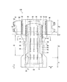
図1は、着用者の肌に面する肌面側から見た吸収性物品の平面図である。図1は、吸収性物品100を構成するシートの皺がなくなる状態まで吸収性物品を伸長させた状態の図である。図2は、図1のA−A線に沿った吸収性物品の断面図である。
FIG. 1 is a plan view of an absorbent article as seen from the skin surface side facing the wearer's skin. FIG. 1 is a diagram showing a state in which the absorbent article is stretched to a state in which the wrinkles of the sheet constituting the
本実施形態に係る吸収性物品は、例えば介護者のような装着補助者が要介護者のような着用者に装着させるタイプのものであることが好ましい。特に、本実施形態に係る吸収性物品は、大人用の使い捨ておむつであることが好ましい。 The absorbent article according to the present embodiment is preferably of a type that a wearer such as a caregiver wears on a wearer such as a care recipient. In particular, the absorbent article according to the present embodiment is preferably a disposable diaper for adults.
吸収性物品1は、着用者の身体前側と身体後側とに延びる前後方向Lと、前後方向Lに直交する幅方向Wと、前後方向L及び幅方向Wに直交する厚み方向Tと、を有する。また、本明細書において、「肌面側」は、使用中に着用者の肌に面する側に相当する。「非肌面側」は、使用中に着用者の肌とは反対に向けられる側に相当する。
The
吸収性物品100は、前胴周り域R1と、後胴周り域R2と、股下域R3と、を有する。前胴周り域R1は、使用時に着用者の身体前側に面する。後胴周り域R2は、使用時に着用者の身体後側に面する。股下域R3は、前胴周り域R1と後胴周り域R2との間に位置し、使用時に着用者の股下に配置される。
The
吸収性物品100は、少なくとも股下域R3及び後胴周り域R2に配置された吸収体40を有する。吸収体40は、股下域R3から前胴周り域R1及び後胴周り域R2へ延びていてよい。
The
吸収性物品100は、吸収体40よりも肌面側に設けられた肌面シート10と、吸収体40よりも非肌面側に設けられた非肌面シート20と、を有する。肌面シート10は、吸収体40を覆っている。肌面シート10は、少なくとも1層の液透過性のシートを含んでいてよい。非肌面シート20は、少なくとも1層の液不透過性のシートを含んでいてよい。
The
吸収性物品100は、後胴周り域R2の幅方向Wの両外側部に設けられたファスニングテープ94を有する。ファスニングテープ94は、幅方向Wの両外側部に2つずつ設けられていてよい。この場合、より後側に位置する一対のファスニングテープ94は、着用者の胴周りを締め付け、より前側に位置する一対のファスニングテープ94は、着用者の胴周りよりも下の位置、例えば脚周り付近を締め付けることができる。ファスニングテープ94は、前胴周り域R1に係合する係合部96を有する。係合部96は、多数のフックによって構成されていてもよい。この場合、前胴周り域R1は、係合部96と係合可能なループ領域98を有していてよい。
The
具体的一例として、ファスニングテープ94は、フラップシート90に形成されていてよい。フラップシート90は、肌面シート10及び非肌面シート20よりも幅方向Wの外側に延びている。フラップシート90は、接合部92において、肌面シート10及び/又は非肌面シート20に接合されていてよい。フラップシート90の接合力を高める観点から、肌面シート10及び/又は非肌面シート20は、肌面シート10と非肌面シート20の両方に接合されていてもよい。
As a specific example, the
吸収性物品100は、少なくとも股下域R3で前後方向Lに延び、肌面側に設けられたギャザーを有する。本実施形態では、ギャザーは、幅方向Wの内側部が起立可能な内向きギャザー50と、幅方向Wの外側部が起立可能な外向きギャザー60と、を含んでいる。
The
内向きギャザー50は、肌面シート10及び内側弾性部材52によって構成されていてよい。具体的には、肌面シート10の外側部が幅方向Wの内側へ折り返されている。内側弾性部材52は、肌面シート10の外側部の折り返し部分によって包まれている。内側弾性部材52は、伸張された状態で肌面シート10の外側部に取り付けられることによって、肌面シート10の外側部とともにギャザーを構成する。
The inward gather 50 may include the
外向きギャザー60は、幅方向Wの外側部が起立可能に構成されたギャザーシート61と、前後方向Lに沿って延びる複数の弾性部材と、を有する。複数の弾性部材は、第1弾性部材62と第2弾性部材66を含む。第1弾性部材62及び第2弾性部材66は、ギャザーシート61に設けられている。第1弾性部材62及び第2弾性部材66は、伸張された状態でギャザーシート61に取り付けられることによって、ギャザーシート61とともに外向きギャザー60を構成する。
The outward gather 60 includes a gather
第1弾性部材62は、第2弾性部材66よりも幅方向Wの内側に設けられている。第1弾性部材62は、幅方向に間隔をあけて複数設けられていてよい。第2弾性部材66は、複数の弾性部材のうちギャザーシート61の幅方向Wの最も外側に位置する。
The first
本態様に係る吸収性物品では、外向きギャザー60は、幅方向Wの外側部が起立可能に構成されたギャザーシート61を有しており、着用時にギャザーシート61が着用者の肌に密着する。特に、ギャザーシート61の幅方向の外側部が起立可能に構成されているため、起立したギャザーシート61の傾斜は、着用者の肌の傾斜に概ね沿い、面状に着用者の肌にフィットする。これにより、液体の漏れを防止できるという安心感を与えることができる。
In the absorbent article according to this aspect, the outward gather 60 has a gather
ギャザーシート61は、疎水性の不織布によって構成されることが好ましい。これにより、ギャザーシート61を透過して液体が染み出すことを抑制することができる。
The gather
第1弾性部材62、又は第1弾性部材62を前後方向Lに延長した仮想線は、後胴周り領域R2において吸収体40と重複している。第1弾性部材62は、ギャザーシート61とともに前後方向Lに収縮する収縮部63を有する。第1弾性部材62の収縮部63の後側の縁は、吸収性物品100の前後方向Lにおける中心CLよりも後側で、ファスニングテープ96の前側の縁どうしを結ぶ線L1より前方に位置する。これにより、後述するように、第1弾性部材62、及びその収縮部63の後側の端部を、吸収性物品100を着用させる際の目印として利用することができる。
The first
第1弾性部材62、及びその収縮部63の後側の端部を目立ちやすくするため、第1弾性部材62は、ギャザーシート61とは異なる色によって構成されていることが好ましい。具体的一例として、ギャザーシート61は白色であり、第1弾性部材62は青色又は水色である。
In order to make the rear end portion of the first
第1弾性部材62は、収縮部63の後側で収縮部63に隣接して設けられ、63収縮部よりも幅方向Wに広がった自然状態の端部64を有していてよい。自然状態の端部64は、ギャザーシート61に接合されていない。第1弾性部材62の自然状態の端部64が幅方向Wに広がっているため、自然状態の端部64は視認し易い。この自然状態の端部64が収縮部63に隣接して設けられているので、収縮部63の端部、すなわち、吸収性物品100を適切な位置で着用するための目印を目立たせることができる。前述した第1弾性部材62の収縮部63の後側の端部だけでなく第1弾性部材62の自然状態の端部64を目印として利用する場合、自然状態の端部64は、ファスニングテープ94の前側の縁どうしを結ぶ線L1より前方に位置することが好ましい。
The first
第1弾性部材62の収縮部63の後側の縁は、フラップシート90の前側の縁どうしを結ぶ線L2より前方に位置することが好ましい。これにより、フラップシート90が第1弾性部材62の収縮作用によって前後方向Lに収縮することを抑制することができる。したがって、ファスニングテープ94が設けられた領域付近の形状が安定するため、安定的にファスニングテープ94を前胴周り域R1に止着させることができる。
The rear edge of the
第1弾性部材62の収縮部63は、前胴周り域R1のループ領域98よりも後側に設けられていることが好ましい。これにより、第1弾性部材62の収縮作用によってループ領域98に皺が生じることを抑制することができる。したがって、ファスニングテープ94を安定してループ領域98に止着することができる。
The
フラップシート90は、着用者の胴周りのみを覆う長さで形成されていることが好ましい。フラップシート90が、着用者の胴周りよりも股下側まで延びていると、フラップシート90が邪魔になり着用者に吸収性物品を装着させ難くなることがある。さらに、フラップシート90は、着用者の胴周りのみを覆う長さで形成されており、かつ第1弾性部材62の収縮部63の後側の縁が、フラップシート90の前側の縁どうしを結ぶ線L2より前方に位置している場合、第1弾性部材の収縮部63の後側の縁は、着用者の脚の付け根の亀裂部分、すなわち鼠蹊部の下端部に対する位置合わせとして利用でき、かつ、フラップシート90は着用者の胴周りに対する位置合わせとして利用できるようになる。
The
ギャザーシート61は、収縮部63の後側の縁よりも後側でギャザーシートよりも非肌面側のシート、本実施形態では折り返されたギャザーシート61の非肌面側の部分に固定された固定部70を有することが好ましい。この固定部70が存在する領域では、外向きギャザー60は、股下域R3よりも立ち上がり難くなっている、又は立ち上がり不能になっている。
The gather
固定部70によって、収縮部63の後側の縁よりも後側の領域の剛性が高くなり、収縮部63の後側の縁よりも後側の領域の形状が安定する。収縮部63の後側の縁よりも後側の領域はファスニングテープ94が設けられた領域に近い。ファスニングテープ94が設けられた領域付近の形状が安定するため、安定的にファスニングテープ94を前胴周り域R1に止着させることができる。
The fixed
固定部70は、ファスニングテープ94の前側の縁どうしを結ぶ線L1を跨って前後方向Lに延びていることが好ましい。これにより、ファスニングテープ94の前側の縁どうしを結ぶ線L1よりも前方の位置から後方の領域の剛性を高めることができる。したがって、ファスニングテープ94どうしを結ぶ線上の領域の形状がより安定し、安定的にファスニングテープ94を前胴周り域R1に止着させることができる。
The fixed
第2弾性部材66は、第1弾性部材62の収縮部63の後側の縁よりも後側へ延びていることが好ましい。これにより、後胴周り領域R2において、ギャザーシート61の幅方向Wの最も外側の先端は第2弾性部材66の収縮作用によって若干立ち上がる。これにより、着用者が寝た姿勢で尿が背側に伝ったとしても、後胴周り域R2の幅方向における外側から液体が漏れることを抑制することができる。
The second
吸収性物品100は、後胴周り域R2に、幅方向Wに沿った後胴周り弾性部材80を有していてよい。後胴周り弾性部材80は、伸張した状態で後胴周り域R2を構成するシートに取り付けられている。第1弾性部材62は、幅方向Wにおいて後胴周り弾性部材80よりも外側に位置する。第1弾性部材62が、幅方向Wにおいて後胴周り弾性部材80よりも外側に位置するため、第1弾性部材62の収縮部63の端部の位置が、後胴周り弾性部材80の収縮によって変位させられる虞を低減することができる。これにより、第1弾性部材62の収縮部63の端部を目印として機能させ易くすることができる。
The
吸収性物品100は、包装された状態で、折り畳まれていてよい。したがって、吸収性物品100は、包装された状態で折り畳むための前後方向Lに沿って延びる折り線FLを有していてよい。折り線FLは、肌面側からみたときに谷折り線であってよい。好ましくは、折り線FLは、外向きギャザー60を構成する複数の弾性部材62,66が設けられた領域とは異なる領域に形成されている。より好ましくは、折り線FLは、複数の弾性部材62,66が設けられた領域よりも幅方向Wの内側に設けられている。これにより、複数の弾性部材62,66が設けられた領域に折り癖が付くことを抑制することができる。したがって、複数の弾性部材62,66によって構成される外向きギャザー60を着用者の肌に密着させ易くなる。
The
吸収体40は、周囲の吸収材料の目付よりも低い目付の吸収材料、又は吸収材料が存在しない領域からなる複数の低目付領域42を有していてよい。複数の低目付領域42は、前後方向Lに沿って延びており、幅方向Wに互いに間隔をあけて並んでいる。好ましくは、低目付領域42の前後方向Lにおける端部は、吸収性物品100の前後方向Lにおける中心CLよりも後側、かつファスニングテープ94の前側の縁どうしを結ぶ線L1より前方に位置する。
The
吸収体の低目付領域42は、吸収性物品の肌面側から視認することができるか、触ることによって認識することができる。したがって、装着補助者は、視覚又は触覚により、低目付領域42の前後方向Lにおける端部が、吸収性物品100の前後方向Lにおける中心CLよりも後側、かつファスニングテープ94の前側の縁どうしを結ぶ線L1より前方に位置することを認識できる。この低目付領域42の前後方向Lにおける端部の位置は、前後方向Lにおける収縮部63の端部の位置と概ね同じ位置にあるため、目印としての収縮部63の端部の位置の目安として用いることができる。
The low
特に、低目付領域42が吸収性物品100の肌面側から視認できる場合には、吸収体の低目付領域42とその周りの領域との境界、すなわち低目付領域42の端部は、装着補助者の目を引き易い。ここで、複数の低目付領域42は幅方向Wに互いに間隔をあけて並んでいるため、装着補助者の目は、幅方向Wに移動し易い。この低目付領域42の前後方向Lにおける端部の位置は、前後方向における収縮部63の端部の位置と概ね同じ位置にあるため、装着補助者は、第1弾性部材62の収縮部63の端部、すなわち、吸収性物品100を適切な位置で着用するための目印を認知し易くなる。
In particular, when the low
より好ましくは、低目付領域42の前後方向Lにおける端部は、後述するフラップシート90の前側の縁どうしを結ぶ線L2より前方に位置する。これにより、低目付領域42の前後方向Lにおける端部を、前後方向における収縮部63の端部の位置とより近い位置に配置させることができる。
More preferably, the end of the low
また、低目付領域42は、吸収材料が実質的に存在しない領域から構成されていてもよい。この場合、低目付領域42のところで吸収性物品100を積極的に曲げることができるようになるため、使用中に吸収性物品100がヨレにくくなる。
Further, the low
吸収体40は、股下域R3において幅方向Wに括れていてよい。言い換えると、股下域R3における吸収体40の幅方向Wの幅は、前胴周り域R1及び後胴周り域R2における吸収体40の幅方向Wの幅よりも小さい。この場合、外向きギャザー60を構成する第1弾性部材62は、股下域R3における吸収体40の幅方向Wの外側縁よりも外側に位置することが好ましい。これにより、吸収体40の幅方向Wの外側縁と、起立した外向きギャザー60との間に凹部が形成される。したがって、体液が吸収体40の表面に沿って幅方向Wの外側に流れたとしても、体液はこの凹部に溜められる。よって、股下域R3の幅方向Wの外側から体液が漏れることを抑制することができる。
The
(3) 吸収性物品の装着方法
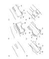
以下、図3(a)〜図3(f)を参照し、上記実施形態に係る吸収性物品100を要介護者のような着用者に装着させる方法について説明する。なお、図3(a)〜図3(f)は、着用者を上方から視認した状態を示している。
(3) Method of Wearing Absorbent Article Hereinafter, a method of wearing the
前述したように、外向きギャザー60を構成する第1弾性部材62は、吸収性物品100を適切な位置で着用するための目印として用いることができる。具体的には、まず、装着補助者は、着用者を仰向けで寝ている状態(図3(a)参照)から横向きに寝かせた状態(図3(b)参照)に変更する。装着補助者は、着用者を横向きに寝かせた状態で、吸収性物品100の中心と着用者の身体の中心とが合うように着用者の臀部の下に吸収性物品100を敷く。このとき、装着補助者は、吸収性物品100の幅方向の中心に対して身体が下になっている側の第1領域101を寄せ集めて、身体の下側付近に寄せるとともに、第1領域101と反対側の第2領域102を広げた状態で敷いておく。ここで、第1弾性部材62、又は第1弾性部材62を前後方向Lに延長した仮想線が後胴周り領域R2において吸収体40と重複しているため、幅方向Wにおける吸収体40の外側端部の位置の目安となる。したがって、装着補助者は、第1弾性部材62を目安に、横向きに寝かせた着用者の臀部の下に、幅方向におけるどの位置に吸収性物品100を配置すればよいか理解し易くなる。
As described above, the first
さらに、第1弾性部材62の収縮部63の後側の縁は、吸収性物品100の前後方向Lにおける中心よりも後側でファスニングテープ94の前側の縁どうしを結ぶ線L1より前方に位置する。この位置は、概ね着用者の脚の付け根の亀裂部分、すなわち鼠蹊部の下端部に相当する。したがって、第1弾性部材62の収縮部63の後側の縁を着用者の脚の付け根の亀裂部分に合わせることで、吸収性物品100の前後方向Lの位置を合わせることができる。ここで、特許文献2のような着色図形ではなく、収縮部63の端部、すなわち収縮部63と非収縮部の境界を目印として利用するため、弾性部材の収縮にともなうギャザーシート61の収縮で目印が視認し難くなるということはない。
Furthermore, the rear edge of the
次いで、装着補助者は、第2領域102上に着用者の身体が乗るように着用者の体位を仰向けに変更する(図3(c)参照)。次いで、装着補助者は、着用者の体位を仰向けの状態から反対側の横向きの状態(図3(d)参照)に変更し、着用者の身体の下から第1領域101を幅方向の外側に引き出す(図3(e)参照)。この際に、第1弾性部材62の収縮部63の端部を目印として、着用者に対する吸収性物品100の位置を微修正してもよい。
Next, the mounting assistant changes the position of the wearer to the back so that the wearer's body is placed on the second region 102 (see FIG. 3C). Next, the mounting assistant changes the body position of the wearer from the supine state to the opposite side-to-side state (see FIG. 3(d)), and the
次いで、装着補助者は、着用者の体位を再度仰向けの状態(図3(f)参照)に変更し、前胴周り域R1によって装着補助者の腹部を覆い、後胴周り域R2に設けられたファスニングテープ94を前胴周り域R1に止着する。これにより、着用補助者は、着用者に吸収性物品100を装着させることができる。
Next, the wearing assistant changes the body position of the wearer to the supine state again (see FIG. 3(f)), covers the abdomen of the wearing assistant with the front waist region R1, and is provided in the back waist region R2. The
以上のように、本態様に係る吸収性物品100では、外向きギャザー60として用いられる第1弾性部材62、及びその収縮部63の端部を、積極的に吸収性物品100を着用させる際の目印として利用することができるので、装着補助者にとって、よりわかり易く、着用者に対して位置決めし易い目印となる。
As described above, in the
ここで、前述したように、第1弾性部材62の自然状態の端部64がファスニングテープ94の前側の縁どうしを結ぶ線L1より前方に位置する場合、第1弾性部材62の自然状態の端部64は、概ね着用者の脚の付け根の亀裂部分、すなわち鼠蹊部の下端部に相当する。したがって、第1弾性部材62の収縮部の後側の端部だけでなく第1弾性部材の自然状態の端部64も、吸収性物品100の前後方向Lの位置合わせをするための目印として用いることができる。第1弾性部材62の自然状態の端部64をも目印として用いる場合、第1弾性部材62の自然状態の端部64はフラップシート90の前側の縁どうしを結ぶ線L2より前方に位置することがより好ましい。
Here, as described above, when the
(4)吸収パッド
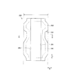
以下、前述した吸収性物品100に使用される吸収パッドの一例について説明する。図4は、一実施形態に係る吸収パッド200の平面図である。図5は、図4のB−B線に沿った吸収パッド200の断面図である。図6は、吸収性物品100に吸収パッド200を配置した状態を示す図である。
(4) Absorption Pad Hereinafter, an example of the absorption pad used in the
吸収パッド200は、吸収性物品100の前後方向に沿った前後方向Lと、前後方向Lに直交する幅方向Wと、を有する。吸収パッド200は、吸収体240を有する。吸収パッド200は、吸収体240よりも肌面側の肌面シート210,250と、吸収体240よりも非肌面側の非肌面シート220と、を有する。
The
肌面シートは、吸収体全体を覆うトップシート210と、トップシート210の幅方向Wの外側部を覆い、吸収体240よりも幅方向Wの外側へ延出するサイドシート250と、を有していてよい。
The skin sheet includes a
吸収パッド200は、幅方向Wにおける最大の幅を有する最大幅部202と、最大幅部202から幅方向Wに括れた括れ部204と、を有していてよい。好ましくは、最大幅部202と括れ部204との境界は、使用時に、吸収性物品100の前後方向Lにおける中心よりも後側で、ファスニングテープ94の前側の縁どうしを結ぶ線L1より前方に位置する。
The
吸収パッド200の最大幅部202と括れ部204との境界と、吸収性物品の第1弾性部材62の収縮部63の後側の端部の両方が、吸収性物品100の前後方向Lにおける中心CLよりも後側で、ファスニングテープ94の前側の縁どうしを結ぶ線L1より前方に位置する。したがって、吸収性物品の第1弾性部材の収縮部63の後側の端部は、吸収パッド200を吸収性物品100に取り付けるときの目印として使用することもできる。具体的には、吸収パッド200の最大幅部202と括れ部204との境界が、吸収性物品の第1弾性部材62の収縮部63の後側の端部に位置するように、吸収パッド200を吸収性物品100に取り付けることで、吸収性物品100上の適切な位置に吸収パッド200を取り付けることができる。
Both the boundary between the
吸収パッド200は、幅方向Wの内側部が起立可能なギャザー250を含んでいてよい。ギャザー250は、例えばサイドシート250と弾性部材252によって構成されていてよい。具体的には、サイドシート250の内側部が幅方向Wの外側へ折り返されている。弾性部材252は、サイドシート250の内側部の折り返し部分によって包まれている。弾性部材252は、伸張された状態でサイドシート250の内側部に取り付けられることによって、サイドシート250の内側部とともにギャザー250を構成する。
The
吸収性物品100上に吸収パッド200を取り付ける際に、吸収パッド200の幅方向Wにおける外側部は、吸収性物品100の内向きギャザー50を構成する肌面シート10の下に挿入されることが好ましい。
When attaching the
好ましくは、股下域R3において吸収性物品100の内向きギャザー50の起立部分の幅方向Wにおける長さG1は、吸収性物品100の股下域R3に相当する吸収パッド200のギャザー250の起立部分の幅方向Wにおける長さG2よりも長い。これにより、吸収パッド200のギャザー250の起立部分を超えて体液が幅方向W外側へ達したとしても、吸収性物品100の内向きギャザー50の起立部分によって、体液の漏れが抑制される。
Preferably, the length G1 in the width direction W of the standing portion of the inward gathers 50 of the
以上、上述の実施形態を用いて本発明について詳細に説明したが、当業者にとっては、本発明が本明細書中に説明した実施形態に限定されるものではないということは明らかである。本発明は、特許請求の範囲の記載により定まる本発明の趣旨及び範囲を逸脱することなく修正及び変更態様として実施することができる。したがって、本明細書の記載は、例示説明を目的とするものであり、本発明に対して何ら制限的な意味を有するものではない。 Although the present invention has been described in detail above using the above-described embodiments, it is obvious to those skilled in the art that the present invention is not limited to the embodiments described in the present specification. The present invention can be implemented as modified and changed modes without departing from the spirit and scope of the present invention defined by the description of the claims. Therefore, the description of the present specification is for the purpose of exemplifying explanation, and does not have any restrictive meaning to the present invention.
10 肌面シート
20 非肌面シート
40 吸収体
42 低目付領域
60 外向きギャザー
61 ギャザーシート
62 第1弾性部材
63 収縮部
64 自然状態の端部
70 固定部
90 フラップシート
94 ファスニングテープ
100 吸収性物品
200 吸収パッド
R1 前胴周り域
R2 後胴周り域
R3 股下域
10 Skin-
Claims (10)
前記前後方向に直交する幅方向と、
前胴周り域と、
後胴周り域と、
前記前胴周り域と前記後胴周り域との間の股下域と、
少なくとも前記股下域及び前記後胴周り域に設けられた吸収体と、
前記後胴周り域の前記幅方向の両外側部に設けられたファスニングテープと、
少なくとも前記股下域で前記前後方向に延び、肌面側に設けられたギャザーと、を有し、
前記ギャザーは、前記幅方向の外側部が起立可能に構成されたギャザーシートと、前記ギャザーシートに設けられ、前記前後方向に沿って延びる複数の弾性部材と、を有し、
前記複数の弾性部材のうちの少なくとも1つの第1弾性部材、又は前記第1弾性部材を前記前後方向に延長した仮想線は、前記後胴周り域において前記吸収体と重複しており、
前記第1弾性部材は、前記ギャザーシートとともに前記前後方向に収縮する収縮部を有し、
前記収縮部の後側の縁は、吸収性物品の前記前後方向における中心よりも後側で、前記ファスニングテープの前側の縁どうしを結ぶ線より前方に位置し、
前記複数の弾性部材のうち前記ギャザーシートの前記幅方向の最も外側に位置する第2弾性部材は、前記収縮部の後側の縁よりも後側へ延びている、吸収性物品。 Back and forth,
A width direction orthogonal to the front-back direction,
Front waist area,
Around the back waist,
Crotch region between the rear waist region and the front waist circumference Ri region,
At least the absorber provided in the crotch region and the rear waist region,
Fastening tapes provided on both outer sides in the width direction of the rear waist region,
At least the crotch region extends in the front-rear direction, and has a gather provided on the skin surface side,
The gather has a gather sheet configured such that an outer side portion in the width direction is erected, and a plurality of elastic members provided on the gather sheet and extending along the front-rear direction,
It said at least one first elastic member of the plurality of elastic members, or a virtual line obtained by extending the first resilient member to the longitudinal direction is overlapped with the absorbent body in the rear cylinder circumferential Ri region,
The first elastic member has a contraction portion that contracts in the front-rear direction together with the gather sheet,
The rear edge of the shrinking portion is located rearward of the center of the absorbent article in the front-rear direction, and is located in front of a line connecting the front edges of the fastening tape,
Of the plurality of elastic members, the second elastic member positioned on the outermost side in the width direction of the gather sheet is an absorbent article, which extends rearward from a rear edge of the contracting portion.
前記収縮部の後側の縁は、前記フラップシートの前側の縁どうしを結ぶ線より前方に位置する、請求項1に記載の吸収性物品。 The rear waist region is a skin sheet provided on the skin side of the absorber, a non-skin sheet provided on the non-skin side of the absorber, the skin sheet and the non-skin sheet. A flap sheet that extends outward in the widthwise direction and that includes the fastening tape,
The absorbent article according to claim 1, wherein a rear edge of the contracting portion is located in front of a line connecting front edges of the flap sheet.
前記複数の低目付領域は、前記前後方向に沿って延びており、前記幅方向に互いに間隔をあけて並んでおり、
前記低目付領域の前記前後方向における端部は、前記吸収性物品の前記前後方向における中心よりも後側、かつ前記ファスニングテープの前側の縁どうしを結ぶ線より前方に位置する、請求項1から4のいずれか1項に記載の吸収性物品。 The absorbent body has a plurality of low basis weight areas composed of an absorbent material having a basis weight lower than that of the surrounding absorbent material, or an area where the absorbent material does not exist,
The plurality of low basis weight regions extend along the front-rear direction, and are arranged side by side in the width direction at intervals from each other,
The end portion in the front-rear direction of the low basis weight region is located rearward of a center of the absorbent article in the front-rear direction and in front of a line connecting front edges of the fastening tape. The absorbent article according to any one of 4 above.
前記折り線は、前記複数の弾性部材が設けられた領域とは異なる領域に形成されている、請求項1から7のいずれか1項に記載の吸収性物品。 A fold line extending along the front-rear direction,
The absorbent article according to any one of claims 1 to 7, wherein the fold line is formed in a region different from a region in which the plurality of elastic members are provided.
前記第1弾性部材は、前記幅方向において前記後胴周り弾性部材よりも外側に位置する、請求項1から8のいずれか1項に記載の吸収性物品。 The rear waist region is provided with a rear waist elastic member along the width direction,
9. The absorbent article according to claim 1, wherein the first elastic member is located outside the rear waistline elastic member in the width direction.
前記最大幅部と前記括れ部との境界は、使用時に、前記吸収性物品の前記前後方向における中心よりも後側で、前記ファスニングテープの前側の縁どうしを結ぶ線より前方に位置する、請求項1から9のいずれか1項に記載の吸収性物品。 A maximum width portion having a maximum width in the front Symbol width direction, and a constricted portion before Symbol maximum width portion constricted in the width direction, the suction pads are arranged to have a,
The boundary between the constricted portion and the maximum width portion, in use, in the absorbent the longitudinal rear than the center in the direction of the article, situated in front of the line connecting the front edge each other of the fastening tape, wherein Item 10. The absorbent article according to any one of items 1 to 9.
Priority Applications (1)
| Application Number | Priority Date | Filing Date | Title |
|---|---|---|---|
| JP2016233557A JP6711739B2 (en) | 2016-11-30 | 2016-11-30 | Absorbent article |
Applications Claiming Priority (1)
| Application Number | Priority Date | Filing Date | Title |
|---|---|---|---|
| JP2016233557A JP6711739B2 (en) | 2016-11-30 | 2016-11-30 | Absorbent article |
Publications (3)
| Publication Number | Publication Date |
|---|---|
| JP2018089014A JP2018089014A (en) | 2018-06-14 |
| JP2018089014A5 JP2018089014A5 (en) | 2019-02-07 |
| JP6711739B2 true JP6711739B2 (en) | 2020-06-17 |
Family
ID=62564731
Family Applications (1)
| Application Number | Title | Priority Date | Filing Date |
|---|---|---|---|
| JP2016233557A Active JP6711739B2 (en) | 2016-11-30 | 2016-11-30 | Absorbent article |
Country Status (1)
| Country | Link |
|---|---|
| JP (1) | JP6711739B2 (en) |
Families Citing this family (2)
| Publication number | Priority date | Publication date | Assignee | Title |
|---|---|---|---|---|
| JP7349272B2 (en) * | 2019-06-20 | 2023-09-22 | ユニ・チャーム株式会社 | absorbent articles |
| JP7160854B2 (en) * | 2020-03-23 | 2022-10-25 | 株式会社リブドゥコーポレーション | absorbent article |
Family Cites Families (6)
| Publication number | Priority date | Publication date | Assignee | Title |
|---|---|---|---|---|
| JP2586287Y2 (en) * | 1993-03-31 | 1998-12-02 | ユニ・チャーム株式会社 | Disposable diapers |
| JP3969822B2 (en) * | 1998-02-23 | 2007-09-05 | 花王株式会社 | Disposable diapers |
| JP3287407B2 (en) * | 1999-06-14 | 2002-06-04 | 花王株式会社 | Diaper |
| CN1273103C (en) * | 2001-12-21 | 2006-09-06 | 宝洁公司 | Disposable absorbent article having elasticized outer leg cuff |
| JP5069639B2 (en) * | 2008-08-20 | 2012-11-07 | 大王製紙株式会社 | Absorbent pad and method for manufacturing the same |
| JP5651800B1 (en) * | 2014-07-31 | 2015-01-14 | ユニ・チャーム株式会社 | Absorbent articles |
-
2016
- 2016-11-30 JP JP2016233557A patent/JP6711739B2/en active Active
Also Published As
| Publication number | Publication date |
|---|---|
| JP2018089014A (en) | 2018-06-14 |
Similar Documents
| Publication | Publication Date | Title |
|---|---|---|
| KR101255592B1 (en) | Disposable diaper | |
| JP5144228B2 (en) | Pants-type disposable diapers | |
| JP4519021B2 (en) | Pants-type disposable diapers | |
| JP4519020B2 (en) | Pants-type disposable diapers | |
| JP2001149409A (en) | Disposable diaper | |
| JP6711739B2 (en) | Absorbent article | |
| JP7025128B2 (en) | Pants-type disposable diapers, how to wear pants-type disposable diapers, and absorbent pads | |
| JP4493435B2 (en) | Pants-type disposable diapers | |
| JP4471769B2 (en) | Pants-type disposable diapers | |
| JP6802407B1 (en) | Absorbent article | |
| JP5149104B2 (en) | Absorbent articles | |
| JP4059814B2 (en) | Disposable diapers | |
| WO2020256104A1 (en) | Absorbent article | |
| JP4024177B2 (en) | Disposable diapers | |
| JP6986494B2 (en) | Absorbent article | |
| JP6396369B2 (en) | Absorbent articles | |
| JP4519027B2 (en) | Pants-type disposable diaper | |
| JP2021106819A (en) | Absorbent article | |
| JP7145838B2 (en) | absorbent article | |
| JP7217219B2 (en) | absorbent article | |
| JP2005198802A (en) | Disposable diaper | |
| JP5173733B2 (en) | Disposable diapers | |
| JP6953784B2 (en) | Tape type diapers | |
| JP6712458B2 (en) | Absorption pad | |
| JP2022002684A (en) | Diaper |
Legal Events
| Date | Code | Title | Description |
|---|---|---|---|
| A521 | Request for written amendment filed |
Free format text: JAPANESE INTERMEDIATE CODE: A523 Effective date: 20181217 |
|
| A621 | Written request for application examination |
Free format text: JAPANESE INTERMEDIATE CODE: A621 Effective date: 20181217 |
|
| A977 | Report on retrieval |
Free format text: JAPANESE INTERMEDIATE CODE: A971007 Effective date: 20191125 |
|
| A131 | Notification of reasons for refusal |
Free format text: JAPANESE INTERMEDIATE CODE: A131 Effective date: 20191203 |
|
| A521 | Request for written amendment filed |
Free format text: JAPANESE INTERMEDIATE CODE: A523 Effective date: 20200203 |
|
| TRDD | Decision of grant or rejection written | ||
| A01 | Written decision to grant a patent or to grant a registration (utility model) |
Free format text: JAPANESE INTERMEDIATE CODE: A01 Effective date: 20200507 |
|
| A61 | First payment of annual fees (during grant procedure) |
Free format text: JAPANESE INTERMEDIATE CODE: A61 Effective date: 20200528 |
|
| R150 | Certificate of patent or registration of utility model |
Ref document number: 6711739 Country of ref document: JP Free format text: JAPANESE INTERMEDIATE CODE: R150 |
|
| R250 | Receipt of annual fees |
Free format text: JAPANESE INTERMEDIATE CODE: R250 |