JP6711312B2 - Vehicle automatic driving control system - Google Patents
Vehicle automatic driving control system Download PDFInfo
- Publication number
- JP6711312B2 JP6711312B2 JP2017095448A JP2017095448A JP6711312B2 JP 6711312 B2 JP6711312 B2 JP 6711312B2 JP 2017095448 A JP2017095448 A JP 2017095448A JP 2017095448 A JP2017095448 A JP 2017095448A JP 6711312 B2 JP6711312 B2 JP 6711312B2
- Authority
- JP
- Japan
- Prior art keywords
- vehicle
- automatic driving
- steering angle
- driving control
- collision
- Prior art date
- Legal status (The legal status is an assumption and is not a legal conclusion. Google has not performed a legal analysis and makes no representation as to the accuracy of the status listed.)
- Active
Links
- 230000008859 change Effects 0.000 claims description 71
- 230000006870 function Effects 0.000 claims description 33
- 238000001514 detection method Methods 0.000 claims description 25
- 230000007935 neutral effect Effects 0.000 claims description 7
- 238000002360 preparation method Methods 0.000 claims description 4
- 238000012546 transfer Methods 0.000 claims description 2
- 238000000034 method Methods 0.000 description 113
- 230000008569 process Effects 0.000 description 52
- 238000012545 processing Methods 0.000 description 15
- 238000004891 communication Methods 0.000 description 9
- HBBGRARXTFLTSG-UHFFFAOYSA-N Lithium ion Chemical compound [Li+] HBBGRARXTFLTSG-UHFFFAOYSA-N 0.000 description 7
- 229910001416 lithium ion Inorganic materials 0.000 description 7
- 230000000694 effects Effects 0.000 description 4
- 230000004048 modification Effects 0.000 description 4
- 238000012986 modification Methods 0.000 description 4
- 230000036626 alertness Effects 0.000 description 3
- 238000013459 approach Methods 0.000 description 3
- 230000007246 mechanism Effects 0.000 description 3
- PXHVJJICTQNCMI-UHFFFAOYSA-N Nickel Chemical compound [Ni] PXHVJJICTQNCMI-UHFFFAOYSA-N 0.000 description 2
- 238000004364 calculation method Methods 0.000 description 2
- 238000002485 combustion reaction Methods 0.000 description 2
- 238000010586 diagram Methods 0.000 description 2
- 210000003128 head Anatomy 0.000 description 2
- 230000003340 mental effect Effects 0.000 description 2
- 230000004044 response Effects 0.000 description 2
- UFHFLCQGNIYNRP-UHFFFAOYSA-N Hydrogen Chemical compound [H][H] UFHFLCQGNIYNRP-UHFFFAOYSA-N 0.000 description 1
- 239000002253 acid Substances 0.000 description 1
- 238000013473 artificial intelligence Methods 0.000 description 1
- 230000006399 behavior Effects 0.000 description 1
- 230000008901 benefit Effects 0.000 description 1
- 230000033228 biological regulation Effects 0.000 description 1
- 238000004422 calculation algorithm Methods 0.000 description 1
- 238000004590 computer program Methods 0.000 description 1
- 230000007423 decrease Effects 0.000 description 1
- 238000013135 deep learning Methods 0.000 description 1
- 239000000446 fuel Substances 0.000 description 1
- 229910052739 hydrogen Inorganic materials 0.000 description 1
- 239000001257 hydrogen Substances 0.000 description 1
- 230000000116 mitigating effect Effects 0.000 description 1
- 229910052759 nickel Inorganic materials 0.000 description 1
- 238000004088 simulation Methods 0.000 description 1
- 239000007787 solid Substances 0.000 description 1
Images


Classifications
-
- B—PERFORMING OPERATIONS; TRANSPORTING
- B60—VEHICLES IN GENERAL
- B60W—CONJOINT CONTROL OF VEHICLE SUB-UNITS OF DIFFERENT TYPE OR DIFFERENT FUNCTION; CONTROL SYSTEMS SPECIALLY ADAPTED FOR HYBRID VEHICLES; ROAD VEHICLE DRIVE CONTROL SYSTEMS FOR PURPOSES NOT RELATED TO THE CONTROL OF A PARTICULAR SUB-UNIT
- B60W30/00—Purposes of road vehicle drive control systems not related to the control of a particular sub-unit, e.g. of systems using conjoint control of vehicle sub-units
- B60W30/08—Active safety systems predicting or avoiding probable or impending collision or attempting to minimise its consequences
- B60W30/09—Taking automatic action to avoid collision, e.g. braking and steering
-
- B—PERFORMING OPERATIONS; TRANSPORTING
- B60—VEHICLES IN GENERAL
- B60R—VEHICLES, VEHICLE FITTINGS, OR VEHICLE PARTS, NOT OTHERWISE PROVIDED FOR
- B60R16/00—Electric or fluid circuits specially adapted for vehicles and not otherwise provided for; Arrangement of elements of electric or fluid circuits specially adapted for vehicles and not otherwise provided for
- B60R16/02—Electric or fluid circuits specially adapted for vehicles and not otherwise provided for; Arrangement of elements of electric or fluid circuits specially adapted for vehicles and not otherwise provided for electric constitutive elements
- B60R16/03—Electric or fluid circuits specially adapted for vehicles and not otherwise provided for; Arrangement of elements of electric or fluid circuits specially adapted for vehicles and not otherwise provided for electric constitutive elements for supply of electrical power to vehicle subsystems or for
- B60R16/033—Electric or fluid circuits specially adapted for vehicles and not otherwise provided for; Arrangement of elements of electric or fluid circuits specially adapted for vehicles and not otherwise provided for electric constitutive elements for supply of electrical power to vehicle subsystems or for characterised by the use of electrical cells or batteries
-
- B—PERFORMING OPERATIONS; TRANSPORTING
- B60—VEHICLES IN GENERAL
- B60R—VEHICLES, VEHICLE FITTINGS, OR VEHICLE PARTS, NOT OTHERWISE PROVIDED FOR
- B60R21/00—Arrangements or fittings on vehicles for protecting or preventing injuries to occupants or pedestrians in case of accidents or other traffic risks
- B60R21/01—Electrical circuits for triggering passive safety arrangements, e.g. airbags, safety belt tighteners, in case of vehicle accidents or impending vehicle accidents
- B60R21/017—Electrical circuits for triggering passive safety arrangements, e.g. airbags, safety belt tighteners, in case of vehicle accidents or impending vehicle accidents including arrangements for providing electric power to safety arrangements or their actuating means, e.g. to pyrotechnic fuses or electro-mechanic valves
-
- B—PERFORMING OPERATIONS; TRANSPORTING
- B60—VEHICLES IN GENERAL
- B60W—CONJOINT CONTROL OF VEHICLE SUB-UNITS OF DIFFERENT TYPE OR DIFFERENT FUNCTION; CONTROL SYSTEMS SPECIALLY ADAPTED FOR HYBRID VEHICLES; ROAD VEHICLE DRIVE CONTROL SYSTEMS FOR PURPOSES NOT RELATED TO THE CONTROL OF A PARTICULAR SUB-UNIT
- B60W10/00—Conjoint control of vehicle sub-units of different type or different function
- B60W10/20—Conjoint control of vehicle sub-units of different type or different function including control of steering systems
-
- B—PERFORMING OPERATIONS; TRANSPORTING
- B60—VEHICLES IN GENERAL
- B60W—CONJOINT CONTROL OF VEHICLE SUB-UNITS OF DIFFERENT TYPE OR DIFFERENT FUNCTION; CONTROL SYSTEMS SPECIALLY ADAPTED FOR HYBRID VEHICLES; ROAD VEHICLE DRIVE CONTROL SYSTEMS FOR PURPOSES NOT RELATED TO THE CONTROL OF A PARTICULAR SUB-UNIT
- B60W10/00—Conjoint control of vehicle sub-units of different type or different function
- B60W10/24—Conjoint control of vehicle sub-units of different type or different function including control of energy storage means
-
- B—PERFORMING OPERATIONS; TRANSPORTING
- B60—VEHICLES IN GENERAL
- B60W—CONJOINT CONTROL OF VEHICLE SUB-UNITS OF DIFFERENT TYPE OR DIFFERENT FUNCTION; CONTROL SYSTEMS SPECIALLY ADAPTED FOR HYBRID VEHICLES; ROAD VEHICLE DRIVE CONTROL SYSTEMS FOR PURPOSES NOT RELATED TO THE CONTROL OF A PARTICULAR SUB-UNIT
- B60W30/00—Purposes of road vehicle drive control systems not related to the control of a particular sub-unit, e.g. of systems using conjoint control of vehicle sub-units
- B60W30/08—Active safety systems predicting or avoiding probable or impending collision or attempting to minimise its consequences
- B60W30/095—Predicting travel path or likelihood of collision
- B60W30/0956—Predicting travel path or likelihood of collision the prediction being responsive to traffic or environmental parameters
-
- B—PERFORMING OPERATIONS; TRANSPORTING
- B60—VEHICLES IN GENERAL
- B60W—CONJOINT CONTROL OF VEHICLE SUB-UNITS OF DIFFERENT TYPE OR DIFFERENT FUNCTION; CONTROL SYSTEMS SPECIALLY ADAPTED FOR HYBRID VEHICLES; ROAD VEHICLE DRIVE CONTROL SYSTEMS FOR PURPOSES NOT RELATED TO THE CONTROL OF A PARTICULAR SUB-UNIT
- B60W30/00—Purposes of road vehicle drive control systems not related to the control of a particular sub-unit, e.g. of systems using conjoint control of vehicle sub-units
- B60W30/18—Propelling the vehicle
- B60W30/18009—Propelling the vehicle related to particular drive situations
- B60W30/18154—Approaching an intersection
-
- B—PERFORMING OPERATIONS; TRANSPORTING
- B60—VEHICLES IN GENERAL
- B60W—CONJOINT CONTROL OF VEHICLE SUB-UNITS OF DIFFERENT TYPE OR DIFFERENT FUNCTION; CONTROL SYSTEMS SPECIALLY ADAPTED FOR HYBRID VEHICLES; ROAD VEHICLE DRIVE CONTROL SYSTEMS FOR PURPOSES NOT RELATED TO THE CONTROL OF A PARTICULAR SUB-UNIT
- B60W40/00—Estimation or calculation of non-directly measurable driving parameters for road vehicle drive control systems not related to the control of a particular sub unit, e.g. by using mathematical models
- B60W40/08—Estimation or calculation of non-directly measurable driving parameters for road vehicle drive control systems not related to the control of a particular sub unit, e.g. by using mathematical models related to drivers or passengers
-
- G—PHYSICS
- G06—COMPUTING; CALCULATING OR COUNTING
- G06V—IMAGE OR VIDEO RECOGNITION OR UNDERSTANDING
- G06V20/00—Scenes; Scene-specific elements
- G06V20/50—Context or environment of the image
- G06V20/56—Context or environment of the image exterior to a vehicle by using sensors mounted on the vehicle
- G06V20/58—Recognition of moving objects or obstacles, e.g. vehicles or pedestrians; Recognition of traffic objects, e.g. traffic signs, traffic lights or roads
- G06V20/584—Recognition of moving objects or obstacles, e.g. vehicles or pedestrians; Recognition of traffic objects, e.g. traffic signs, traffic lights or roads of vehicle lights or traffic lights
-
- G—PHYSICS
- G08—SIGNALLING
- G08G—TRAFFIC CONTROL SYSTEMS
- G08G1/00—Traffic control systems for road vehicles
- G08G1/16—Anti-collision systems
-
- H—ELECTRICITY
- H02—GENERATION; CONVERSION OR DISTRIBUTION OF ELECTRIC POWER
- H02J—CIRCUIT ARRANGEMENTS OR SYSTEMS FOR SUPPLYING OR DISTRIBUTING ELECTRIC POWER; SYSTEMS FOR STORING ELECTRIC ENERGY
- H02J7/00—Circuit arrangements for charging or depolarising batteries or for supplying loads from batteries
-
- B—PERFORMING OPERATIONS; TRANSPORTING
- B60—VEHICLES IN GENERAL
- B60T—VEHICLE BRAKE CONTROL SYSTEMS OR PARTS THEREOF; BRAKE CONTROL SYSTEMS OR PARTS THEREOF, IN GENERAL; ARRANGEMENT OF BRAKING ELEMENTS ON VEHICLES IN GENERAL; PORTABLE DEVICES FOR PREVENTING UNWANTED MOVEMENT OF VEHICLES; VEHICLE MODIFICATIONS TO FACILITATE COOLING OF BRAKES
- B60T7/00—Brake-action initiating means
- B60T7/12—Brake-action initiating means for automatic initiation; for initiation not subject to will of driver or passenger
-
- B—PERFORMING OPERATIONS; TRANSPORTING
- B60—VEHICLES IN GENERAL
- B60W—CONJOINT CONTROL OF VEHICLE SUB-UNITS OF DIFFERENT TYPE OR DIFFERENT FUNCTION; CONTROL SYSTEMS SPECIALLY ADAPTED FOR HYBRID VEHICLES; ROAD VEHICLE DRIVE CONTROL SYSTEMS FOR PURPOSES NOT RELATED TO THE CONTROL OF A PARTICULAR SUB-UNIT
- B60W2540/00—Input parameters relating to occupants
- B60W2540/18—Steering angle
-
- B—PERFORMING OPERATIONS; TRANSPORTING
- B60—VEHICLES IN GENERAL
- B60W—CONJOINT CONTROL OF VEHICLE SUB-UNITS OF DIFFERENT TYPE OR DIFFERENT FUNCTION; CONTROL SYSTEMS SPECIALLY ADAPTED FOR HYBRID VEHICLES; ROAD VEHICLE DRIVE CONTROL SYSTEMS FOR PURPOSES NOT RELATED TO THE CONTROL OF A PARTICULAR SUB-UNIT
- B60W2554/00—Input parameters relating to objects
- B60W2554/80—Spatial relation or speed relative to objects
-
- G—PHYSICS
- G06—COMPUTING; CALCULATING OR COUNTING
- G06V—IMAGE OR VIDEO RECOGNITION OR UNDERSTANDING
- G06V20/00—Scenes; Scene-specific elements
- G06V20/50—Context or environment of the image
- G06V20/59—Context or environment of the image inside of a vehicle, e.g. relating to seat occupancy, driver state or inner lighting conditions
- G06V20/597—Recognising the driver's state or behaviour, e.g. attention or drowsiness
-
- G—PHYSICS
- G08—SIGNALLING
- G08G—TRAFFIC CONTROL SYSTEMS
- G08G1/00—Traffic control systems for road vehicles
- G08G1/16—Anti-collision systems
- G08G1/166—Anti-collision systems for active traffic, e.g. moving vehicles, pedestrians, bikes
Landscapes
- Engineering & Computer Science (AREA)
- Mechanical Engineering (AREA)
- Transportation (AREA)
- Automation & Control Theory (AREA)
- Physics & Mathematics (AREA)
- Chemical & Material Sciences (AREA)
- General Physics & Mathematics (AREA)
- Combustion & Propulsion (AREA)
- Mathematical Physics (AREA)
- Theoretical Computer Science (AREA)
- Multimedia (AREA)
- Power Engineering (AREA)
- Traffic Control Systems (AREA)
- Control Of Driving Devices And Active Controlling Of Vehicle (AREA)
- Steering Control In Accordance With Driving Conditions (AREA)
- Regulating Braking Force (AREA)
Description
本発明は、車両の自動運転制御システムに関する。 The present invention relates to a vehicle automatic driving control system.
特許文献1には、車両の自動運転システムが開示されている。この自動運転システムでは、障害物及び自車両の移動軌道をシミュレートした上で、様々な物体(他車両やガードレール等)との衝突発生の組み合わせ毎に損害度を演算し、最も損害度が低くなる様に車両を自動制御する。例えば、損害度が低くなるように自車両を制御するために、ガードレールへ接触することで自車両を停止させて歩行者を保護することが記載されている。 Patent Document 1 discloses an automatic vehicle driving system. This automatic driving system simulates the movement trajectory of obstacles and own vehicle, and then calculates the degree of damage for each combination of collisions with various objects (other vehicles, guardrails, etc.), and the degree of damage is the lowest. The vehicle is automatically controlled so that For example, in order to control the own vehicle so that the degree of damage is reduced, it is described that the own vehicle is stopped by contacting a guardrail to protect a pedestrian.
しかしながら、従来の自動運転システムでは、他の物体との衝突による電源系統への影響を緩和する点に関しては、対策が十分になされていないのが実情であった。例えば、他の車両との衝突によって自車両の電源系統に短絡や電源喪失が発生すると、二次被害を防ぐための機器への電力供給が失われるなどの各種の故障や不具合が発生してしまい、自車両を安全に動作させることができなくなる可能性がある。 However, in the conventional automatic driving system, the actual situation is that measures have not been taken sufficiently to reduce the influence on the power supply system due to the collision with other objects. For example, if a short-circuit or power loss occurs in the power supply system of the own vehicle due to a collision with another vehicle, various failures and problems such as loss of power supply to equipment to prevent secondary damage will occur. , It may not be possible to operate the own vehicle safely.
本発明は、上述の課題の少なくとも一部を解決するためになされたものであり、以下の形態として実現することが可能である。 The present invention has been made to solve at least a part of the problems described above, and can be realized as the following modes.
本発明の一形態によれば、自車両(50)を走行予定経路に沿って走行させる自動運転を実行する自動運転制御システム(100)が提供される。この自動運転制御システムは、前記自車両に設置され、それぞれ、前記自車両の特定補機(200,220,320,330,340,410,420,610)に対して電力を供給可能な複数の電源(621,622)と、前記特定補機に対する前記複数の電源の接続状態を変更するリレー装置(630)と、前記リレー装置を制御するリレー制御装置(610)と、前記走行予定経路における前記自車両の状況と、前記自車両の周辺における他の物体の状況とを認知可能な状況認知部(220)と、前記リレー制御装置に前記複数の電源の接続状態を指示し自動運転の制御を行う自動運転制御部(210)と、を備える。前記状況認知部は、前記自動運転中における前記自車両の前記他の物体と衝突する衝突確率が所定閾値以上であること、および、前記衝突確率が前記所定閾値以上である場合に、前記複数の電源のうち、前記他の物体との衝突により破損が発生すると予期される破損予期電源を認知し、前記自動運転制御部は、前記衝突確率が前記所定閾値以上である場合に、前記破損予期電源を前記特定補機から切り離すとともに、前記複数の電源のうち前記破損予期電源でない電源を前記特定補機に接続するよう、前記リレー制御装置に指示を行う。また、前記状況認知部は、前記衝突確率が前記所定閾値以上であることを認知した場合に、前記自動運転制御部が採用し得る複数の自動運転動作に関するコストを算出し、前記コストが最小となる自動運転動作を採用するとともに、当該採用した自動運転動作において前記他の物体が衝突すると予期される前記自車両の部位を決定する。 According to an aspect of the present invention, there is provided an automatic driving control system (100) that executes an automatic driving that causes a vehicle (50) to travel along a planned travel route. This automatic driving control system is installed in the own vehicle and is capable of supplying electric power to specific accessories (200, 220, 320, 330, 340, 410, 420, 610) of the own vehicle. A power source (621, 622), a relay device (630) that changes the connection state of the plurality of power sources to the specific auxiliary device, a relay control device (610) that controls the relay device, and the relay device in the planned travel route. A situation recognition unit (220) capable of recognizing the situation of the own vehicle and the situation of other objects in the vicinity of the own vehicle, and the relay control device to instruct the connection state of the plurality of power sources to control automatic driving. And an automatic operation control unit (210) for performing the operation. The situation recognition unit, the collision probability of colliding with the other object of the own vehicle during the automatic driving is a predetermined threshold value or more, and, if the collision probability is the predetermined threshold value or more, the plurality of Among the power supplies, the damage expected power supply that is expected to be damaged due to the collision with the other object is recognized, and the automatic driving control unit, when the collision probability is the predetermined threshold or more, the damage expected power supply. Is disconnected from the specific auxiliary machine, and the relay control device is instructed to connect a power supply, which is not the damage expected power supply, of the plurality of power supplies to the specific auxiliary machine. Further, the situation recognition unit, when recognizing that the collision probability is equal to or more than the predetermined threshold, calculates a cost related to a plurality of automatic driving operations that the automatic driving control unit can adopt, and the cost is the minimum. In addition to adopting the following automatic driving operation, the part of the host vehicle that is expected to collide with the other object in the adopted automatic driving operation is determined.
この形態の自動運転制御システムによれば、自車両が他の物体と衝突する衝突確率が所定閾値以上である場合に、他の物体との衝突により破損が発生すると予期される破損予期電源を特定補機から切り離すとともに、破損予期電源でない電源を特定補機に接続するようリレー制御装置に指示を行うので、衝突が発生したとしても、特定補機に電力を継続して供給することが可能となり、破損予期電源の破損や特定補機の電源喪失によって二次被害が発生する可能性を低減できる。 According to the automatic driving control system of this aspect, when the collision probability that the own vehicle collides with another object is equal to or higher than a predetermined threshold value, the expected damage power source that is expected to be damaged due to the collision with another object is identified. In addition to disconnecting from the auxiliary machine, the relay control device is instructed to connect the power supply that is not the damage expected power supply to the specific auxiliary machine, so even if a collision occurs, it is possible to continue supplying power to the specific auxiliary machine. Damage expected It is possible to reduce the possibility that secondary damage will occur due to damage to the power supply or loss of power to the specified auxiliary equipment.
A. 第1実施形態:
図1に示すように、第1実施形態の車両50は、自動運転制御システム100を備える。自動運転制御システム100は、自動運転ECU200(Electronic Control Unit)と、車両制御部300と、支援情報取得部400と、ドライバ警告部500と、電源部600とを備える。なお、本明細書において、車両50を「自車両50」とも呼ぶ。
A. First embodiment:
As shown in FIG. 1, the
自動運転ECU200は、CPUとメモリとを含む回路である。自動運転ECU200は、不揮発性記憶媒体に格納されたコンピュータプログラムを実行することによって、車両50の自動運転の制御を行う自動運転制御部210,及び、車両50に関する状況を認知する状況認知部220として機能する。状況認知部220の機能については後述する。
The automatic driving ECU 200 is a circuit including a CPU and a memory. The autonomous driving
車両制御部300は、車両50の運転のための各種の制御を実行する部分であり、自動運転と手動運転のいずれの場合にも利用される。車両制御部300は、駆動部制御装置310と、ブレーキ制御装置320と、操舵角制御装置330と、一般センサ類340とを含む。駆動部制御装置310は、車両50の車輪を駆動する駆動部(図示せず)を制御する機能を有する。車輪の駆動部としては、内燃機関と電動モータのうちの1つ以上の原動機を使用可能である。ブレーキ制御装置320は、車両50のブレーキ制御を実行する。ブレーキ制御装置320は、例えば電子制御ブレーキシステム(ECB)として構成される。操舵角制御装置330は、車両50の車輪の操舵角を制御する。なお、第1実施形態において「操舵角」とは、車両50の2つの前輪の平均操舵角を意味する。操舵角制御装置330は、例えば電動パワーステアリングシステム(EPS)として構成される。一般センサ類340は、車速センサ342と操舵角センサ344を含んでおり、車両50の運転に必要とされる一般的なセンサ類である。一般センサ類340は、自動運転と手動運転のいずれの場合にも利用されるセンサを含んでいる。
The
支援情報取得部400は、自動運転のための各種の支援情報を取得する。支援情報取得部400は、前方検出装置410と、後方検出装置420と、GPS装置430と、ナビゲーション装置440と、無線通信装置450とを含んでいる。ナビゲーション装置440は、目的地とGPS装置430で検出される自車位置とに基づいて、自動運転における走行予定経路を決定する機能を有する。走行予定経路の決定や修正のために、GPS装置430に加えて、ジャイロ等の他のセンサを利用してもよい。前方検出装置410は、自車両50の前方に存在する物体や道路設備(車線、交差点、信号機等)の状況に関する情報を取得する。後方検出装置420は、自車両50の後方に存在する物体や道路設備に関する情報を取得する。前方検出装置410と後方検出装置420のそれぞれは、例えば、カメラや、レーザーレーダー、ミリ波レーダーなどの各種の検出器から選ばれた1つ以上の検出器を用いて実現可能である。無線通信装置450は、高度道路交通システム70(Intelligent Transport System)との無線通信によって自車両50の状況や周囲の状況に関する状況情報を交換することが可能であり、また、他車両60との車車間通信や、道路設備に設置された路側無線機との路車間通信を行って状況情報を交換することも可能である。支援情報取得部400は、このような無線通信を介して得られる状況情報を利用して、自車の走行状況に関する情報と、自車両50の前方の状況に関する情報と、自車両50の後方の状況に関する情報と、の一部を取得するようにしてもよい。支援情報取得部400によって取得された各種の支援情報は、自動運転ECU200に送信される。
The support
本明細書において「自動運転」とは、ドライバ(運転者)が運転操作を行うことなく、駆動部制御とブレーキ制御と操舵角制御のすべてを自動で実行する運転を意味する。従って、自動運転では、駆動部の動作状態と、ブレーキ機構の動作状態と、車輪の操舵角が、自動的に決定される。「手動運転」とは、駆動部制御のための操作(アクセルペダルの踏込)と、ブレーキ制御のための操作(ブレーキベダルの踏込)と、操舵角制御のための操作(ステアリングホイールの回転)を、ドライバが実行する運転を意味する。 In the present specification, “automatic driving” means driving in which all of drive unit control, brake control, and steering angle control are automatically executed without a driver (driver) performing a driving operation. Therefore, in the automatic driving, the operating state of the drive unit, the operating state of the brake mechanism, and the steering angle of the wheels are automatically determined. "Manual operation" includes operations for controlling the drive unit (depression of the accelerator pedal), operations for brake control (depression of the brake pedal), and operations for steering angle control (rotation of the steering wheel). , Means the driving performed by the driver.
自動運転制御部210は、ナビゲーション装置440から与えられた走行予定経路と、状況認知部220で認知された各種の状況とに基づいて、自動運転を制御する。具体的には、自動運転制御部210は、駆動部(エンジンやモータ)の動作状態を示す駆動指示値を駆動部制御装置310に送信し、ブレーキ機構の動作状態を示すブレーキ指示値をブレーキ制御装置320に送信し、車輪の操舵角を示す操舵角指示値を操舵角制御装置330に送信する。各制御装置310,320,330は、与えられた指示値に従ってそれぞれの制御対象機構の制御を実行する。なお、自動運転制御部210の各種の機能は、例えばディープラーニングなどの学習アルゴリズムを利用した人工知能により実現可能である。
The automatic
ドライバ警告部500は、ドライバ状態検出部510と、警告装置520とを含んでいる。ドライバ状態検出部510は、カメラ等の検出器(図示省略)を含んでおり、自車両50のドライバの顔や頭の状態等を検出することによって、ドライバがどのような状態にあるかを検出する機能を有する。警告装置520は、車両50の状況やドライバ状態検出部510の検出結果に応じて、ドライバに警告を発生する装置である。警告装置520は、例えば、音声発生装置(スピーカー)や、画像表示装置、車室内の物体(例えばステアリングホイール)に振動を発生させる振動発生装置などの1つ以上の装置を用いて構成することが可能である。なお、ドライバ警告部500を省略してもよい。
The
電源部600は、車両50内の各部に電源を供給する部分であり、電源制御装置としての電源制御ECU610と、電源回路620とを備える。電源回路620は、複数の電源621,622を有している。複数の電源621,622としては、例えば、2次電池や燃料電池を利用可能である。
The
自動運転ECU200で実現される状況認知部220は、走行状況認知部222と、前方認知部224と、後方認知部226とを含んでいる。走行状況認知部222は、支援情報取得部400及び一般センサ類340から提供される各種の情報や検出値を利用して、自車両50の走行状況を認知する機能を有する。前方認知部224は、前方検出装置410から提供される情報を利用して、自車両50の前方の物体や道路設備(車線、交差点、信号機等)の状況を認知する。後方認知部226は、自車両50の後方の物体や道路設備に関する状況を認知する。例えば、前方認知部224や後方認知部226は、他の物体が自車両50に近接する近接状況を認知可能である。なお、状況認知部220の機能の一部又は全部を、自動運転ECU200とは別個の1つ以上のECUによって実現するようにしてもよい。
The
自動運転制御システム100は、自動運転ECU200を含む多数の電子機器を有している。これらの複数の電子機器は、CAN(Controller Area Network)などの車載ネットワークを介して互いに接続されている。なお、図1に示す自動運転制御システム100の構成は、後述する他の実施形態においても使用可能である。
The automatic
図2に示すように、電源回路620は、複数の電源621,622と、複数のリレー631,632を含むリレー装置630と、電源配線625とを有している。この例では、第1電源621が第1リレー631を介して電源配線625に接続されており、第2電源622が第2リレー632を介して電源配線625に接続されている。電源配線625は、複数の特定補機に電力を供給する。ここでは、特定補機として、前方検出装置410と、後方検出装置420と、自動運転ECU200と、電源制御ECU610と、駆動部制御装置310と、ブレーキ制御装置320と、操舵角制御装置330と、一般センサ類340とが描かれている。特定補機は、例えば、自動運転の制御を行うために必要となる機器類のうちで特に重要な機器である。なお、「補機」とは、車輪の駆動部(内燃機関や電動モータ)を用いて車両50を走行させるために必要な機器類を意味する。特定補機以外の補機は、図2の電源系統に接続されていてもよく、他の電源系統に接続されていてもよい。電源回路620の通常接続状態では、図2に示すように、複数の電源621,622が複数の特定補機に並列に接続される。電源制御ECU610は、リレー装置630の接続状態を切り替えるリレー制御装置としての機能を有する。なお、図2の例では、リレー装置630は2つのリレー631,632を含む単純な構成を有するものとしたが、より複雑な構成のリレー装置630を任意に採用可能である。一般には、リレー装置630は、電源回路620の接続状態を変更な複数のリレーを含む回路として構成可能である。
As shown in FIG. 2, the
第1電源621は、車両50の前端部の近傍に設置されており、第2電源622は車両50の後端部の近傍に設置されている。この例ように、複数の電源621,622は、車両50の異なる部位に配置されていることが好ましい。例えば、複数の電源621,622は、車両50の前端部と、後端部と、右側端部と、左側端部と、中央部のうちから選ばれた2つ以上の異なる部位に分散して配置されていることが好ましい。図2の例では、電源の数を2としたが、3つ以上の電源を設けるようにしてもよい。また、図2の電源回路620において、ヒューズ等の過電流保護回路や、過電圧保護回路を設けてもよい。更に、電源電圧の調整のために、DC−DCコンバータを設けるようにしてもよい。たとえば、複数の電源621,622は、両方ともに鉛蓄電池である。もしくは、複数の電源621,622は、両方ともにリチウムイオン2次電池である。もしくは、複数の電源621,622は両方ともにニッケル水素蓄電池である。その他、複数の電源621,622は、様々な種類の電源を組み合わせを利用可能である。
The
車両が左側走行することを定めた交通法規が適用される地域では、一般に、車両の右側後方からの部分衝突と比較し、車両の左側後方からの部分衝突の可能性が高い。この理由は、右折待ちでは、車両は車線の右側に寄っているためである。このため、車両の後方に複数の電源621,622を設置する場合は、車両の右側後方に設置するのが好ましい。一方、車両が右側走行することを定めた交通法規が適用される地域では、逆に、複数の電源621,622を車両の左側後方に設置するのが好ましい。また、複数の電源621,622が鉛蓄電池とリチウムイオン電池の組み合わせであった場合に、リチウムイオン電池を鉛蓄電池より車両の内側に位置するように配置するレイアウトが好ましい。これによれば、一般に高出力であり特定補機への電力供給能力が高いリチウムイオン電池を、鉛蓄電池より、衝突破損し難い位置に配置することができる。また、他に好ましいレイアウトとして、リチウムイオン電池を鉛蓄電池より車両の前方に配置するのが好ましい。これによれば、リチウムイオン電池を、鉛蓄電池より、後方から衝突されることによる破損がし難い位置に配置することができる。この場合、たとえば、リチウムイオン電池は、キャビン内の助手席下スペースや、エンジンフードの中に配置することができる。
In an area to which a traffic law that specifies that a vehicle travels to the left is applied, a partial collision from the left rear side of the vehicle is generally more likely than a partial collision from the right rear side of the vehicle. The reason for this is that the vehicle is approaching the right side of the lane while waiting for a right turn. Therefore, when a plurality of
以下に説明するように、第1実施形態において自動運転制御部210は、自動運転中において自車両50が他の物体と衝突する衝突確率が所定閾値以上であることを状況認知部220が認知した場合に、電源制御ECU610に、リレー装置630を通常接続状態から緊急接続状態に変更させる。この電源接続切替処理のフローは、図3に示されている。
As described below, in the first embodiment, the autonomous
図3に示すフローは、自動運転制御部210及び状況認知部220によって車両50の動作中に定期的に繰り返し実行される。まず、ステップS10では、自動運転中か否かが判定される。自動運転中で無ければ図3の処理を終了し、自動運転中であればステップS20以降の処理に進む。ステップS20では、状況認知部220が、自車両50が他の物体と衝突する可能性があるか否かを判断する。この判断は、支援情報取得部400で取得された各種の情報に基づいて、状況認知部220によって実行される。他の物体としては、自車両50の周囲で走行又は停止している他の車両や、歩行者、道路設備などの各種の物体を想定することができる。また、衝突確率は、自車両50と他の物体の相対距離や、相対速度、双方の進行方向等の1つ以上のパラメータに基づいて算出可能である。
The flow shown in FIG. 3 is periodically and repeatedly executed by the automatic
図4のグラフでは、衝突確率が高い2つの領域RCR,FCRをハッチングで示している。このグラフの横軸は自車両50と他の物体の相対距離Xrであり、縦軸は相対速度Vrである。相対距離Xrは、他の物体が自車両50の前方にあるときをプラスとし、他の物体が自車両50の後方にあるときをマイナスとしている。相対速度Vrは、他の物体が自車両50よりも高速の場合をプラスとし、他の物体が自車両50よりも低速の場合をマイナスとしている。第1領域RCRは、自車両50が、後方から他の物体(例えば他車両)に追突される可能性が高い後方衝突領域である。第2領域FCRは、自車両50が、前方にある他の物体に衝突する可能性が高い前方衝突領域である。この例から理解できるように、衝突確率は、相対距離Xrの絶対値が小さいほど高く、相対速度Vrの絶対値が大きいほど高くなる傾向にある。衝突確率は、少なくとも相対距離Xrと相対速度Vrを含む複数のパラメータに基づいて算出することが可能である。
In the graph of FIG. 4, two regions RCR and FCR having a high collision probability are hatched. The horizontal axis of this graph is the relative distance Xr between the
状況認知部220は、自車両50が他の物体と衝突する衝突確率が、所定閾値(予め定めた衝突閾値)未満である場合には衝突可能性が無いものと判定する。この場合には、図3の処理も終了する。一方、衝突確率が所定閾値以上の場合には、衝突可能性があるものと判定してステップS30に進む。
The
ステップS30では、状況認知部220が、他の物体との衝突により破損が発生すると予期される自車両50の部位を認知し、その部位に、複数の電源621,622のうちのいずれかの電源が設置されているか否かを判断する。例えば、図2の例において、自車両50が後方から追突される場合には、自車両50の後端部の近傍の部位に破損が発生するものと認知され、その部位に第2電源622が設置されているので、ステップS30の判断が肯定される。以下では、衝突により破損が発生すると予期される部位に設置されており、他の物体との衝突により破損が発生すると予期される電源622を「破損予期電源」と呼ぶ。なお、衝突によりどの部位に破損が発生するかは、自車両50の機械的構造や、他の物体との相対速度、衝突方向、他の物体のサイズや重量などの複数のパラメータを総合的に考慮して推定可能である。これらの複数のパラメータのうち、他の物体が関係するパラメータは、支援情報取得部400によって取得される。また、自車両50の機械的構造に関する情報は、自動運転制御システム100の不揮発性メモリ(図示省略)から取得可能である。ステップS30の判断が否定される場合には、図3の処理を終了する。すなわち、この場合には、電源回路620は、通常接続状態に維持される。一方、ステップS30の判断が肯定される場合には、ステップS40に進む。
In step S30, the
ステップS40では、自動運転制御部210が、電源制御ECU610に、リレー装置630に指示を行わせて、通常接続状態から緊急接続状態に変更させる。緊急接続状態は、衝突により破損が発生すると予期される部位に設置された破損予期電源を特定補機から切り離すとともに、破損予期電源以外の電源を特定補機に接続した状態である。図2の例において、この緊急接続状態は、第1リレー631がオンで第2リレー632がオフの状態である。従って、仮に衝突が発生して自車両50に破損が発生した場合にも、特定補機に電力を継続して供給することが可能となり、特定補機の電源喪失によって二次被害が発生する可能性を低減できる。また、破損予期電源の破損により過電流や過電圧が発生して、他の電源系統に破損を引き起こす可能性を低減できる。この結果、自車両50を安全に動作させることが可能である。
In step S40, the automatic
緊急接続状態において電源から電力の供給を受ける特定補機は、自動運転制御部210と、状況認知部220と、ブレーキ制御装置320と、操舵角制御装置330と、のうちの少なくとも一つを含むように構成することができる。衝突後に自車両50を安全に停止させるという観点からは、各種の補機のうちで、ブレーキ制御装置320の重要度が最も高く、自動運転制御部210と状況認知部220と操舵角制御装置330の重要度がそれに続くと考えられる。従って、緊急接続状態において電源から電力の供給を受ける特定補機は、少なくともブレーキ制御装置320を含むことが好ましく、また、ブレーキ制御装置320に加えて、自動運転制御部210と状況認知部220と操舵角制御装置330を含むことが更に好ましい。
The specific accessory that receives power supply from the power supply in the emergency connection state includes at least one of the automatic
電源部600が3つ以上の電源を有する場合にも、緊急接続状態において、他の物体が衝突すると予期される自車両50の部位に設置された破損予期電源を特定補機から切り離すとともに、破損予期電源以外の1つ以上の電源を特定補機に接続した状態とすることができる。このとき、緊急接続状態において、破損予期電源以外の2つ以上の電源を特定補機に接続した状態とすれば、破損予期電源の破損や特定補機の電源喪失によって二次被害が発生する可能性を更に低減でき、また、自車両50をより安全に運行させることが可能となる。
Even when the
ステップS40で緊急接続状態に変更した後、ステップS50では、衝突が回避されたか否かが判断される。この判断は、ステップS20で判定された衝突の可能性が解消したか否かの判断である。ステップS50は、衝突が回避されるまで繰り返し実行される。衝突が回避された場合には、次のステップS60に進む。ステップS60では、自動運転制御部210が、電源制御ECU610に、電源回路620を通常接続状態に復帰させる。
After changing to the emergency connection state in step S40, it is determined in step S50 whether a collision has been avoided. This determination is a determination as to whether the possibility of collision determined in step S20 has been resolved. Step S50 is repeatedly executed until the collision is avoided. If the collision is avoided, the process proceeds to the next step S60. In step S60, the automatic
以上のように、第1実施形態では、自車両50が他の物体と衝突する衝突確率が所定閾値以上である場合に、他の物体が衝突すると予期される破損予期電源を特定補機から切り離すとともに、破損予期電源以外の1つ以上の電源を特定補機に接続するように、自動運転制御部210が電源制御ECU610に指示を行う。この結果、衝突が発生したとしても、特定補機に電力を継続して供給することが可能となり、破損予期電源の破損や特定補機の電源喪失によって二次被害が発生する可能性を低減できる。また、自車両50を安全に動作させることができる。
As described above, in the first embodiment, when the collision probability that the
B. 第2実施形態:
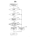
図5に示すように、第2実施形態における電源接続変更処理の手順は、図3のステップS40とステップS50の間にステップS120,S130を追加し、また、ステップS60の後にステップS150,S160を追加したものである。なお、図5の処理手順において、ステップS30の判断が否定される場合には後述するステップS120に進む。
B. Second embodiment:
As shown in FIG. 5, in the procedure of the power supply connection change process in the second embodiment, steps S120 and S130 are added between steps S40 and S50 of FIG. 3, and steps S150 and S160 are added after step S60. It was added. In addition, in the processing procedure of FIG. 5, when the determination of step S30 is denied, it progresses to step S120 mentioned later.
ステップS120,S130において、自動運転制御部210は、自車両50が交差点の中央付近で一時停止中又は徐行中の際に、状況認知部220が予め定められた操舵角変更状況を認知すると、走行予定経路に沿った第1操舵角(自動運転の操舵角指示値で指示された第1操舵角)をこれと異なる第2操舵角に変更することによって、自車両50の後方から他の車両に追突される場合の影響を緩和する。なお、実際の操舵角の変更は、自動運転制御部210が操舵角制御装置330に操舵角を変更させることによって行なわれる。以下の説明において、第1実施形態と同じ符号は、同一の構成を示すものであって、先行する説明を参照する。この点は、後述する他の実施形態も同様である。
In steps S120 and S130, when the
ステップS40において電源回路620が通常接続状態から緊急接続状態に変更された後、ステップS120では、状況認知部220が予め定められた操舵角変更状況を認知したか否かが判断される。状況認知部220が操舵角変更状況を認知した場合には、ステップS130において、車両50の操舵角が、走行予定経路に沿った第1操舵角から第2操舵角に変更され、操舵角変更状況が認知されない場合には第1操舵角がそのまま維持されてステップS50に進む。第2実施形態におけるステップS120の詳細手順の一例は図6に示されている。
After the
図6に示すように、操舵角変更状況の判定処理のステップS200,S210,S220では、以下の3つの条件がすべて成立するか否かが判断される。
<条件1>自車両50の車速が所定値以下である。
<条件2>自車両50が交差点の中央から所定の範囲内に存在する。
<条件3>自車両50の前輪の方向が、交差点における車線直進方向と平行で無い。
As shown in FIG. 6, in steps S200, S210, and S220 of the steering angle change status determination processing, it is determined whether or not all of the following three conditions are satisfied.
<Condition 1> The vehicle speed of the
<Condition 2> The
<Condition 3> The direction of the front wheels of the
条件1における車速の「所定値」は、自車両50がほとんど停止していると評価できる程度の車速であり、例えば2km/時以下の値に設定される。なお、「所定値」をゼロとして、自車両50が停止しているときにのみ条件1が成立するものとしてもよい。条件2の「交差点の中央から所定の範囲」は、交差点の大きさや道路幅等に応じて適宜予め設定される。条件3の「交差点における車線直進方向」とは、自車両50が交差点に進入する前に走行していた車線の直進方向を意味する。
The "predetermined value" of the vehicle speed under the condition 1 is a vehicle speed at which it can be evaluated that the
上述の条件1〜3がすべて成立する場合には、ステップS230に進み、状況認知部220によって操舵角変更状況が認知される。一方、条件1〜3の少なくとも一つが成立しない場合には、ステップS240に進み、操舵角変更状況は認知されない。なお、条件1〜3は、いずれも自車両50の走行状況に関する条件なので、これらを「走行状況条件」とも呼ぶ。
When all of the above conditions 1 to 3 are satisfied, the process proceeds to step S230, and the
上述した走行状況条件のうち、条件2,3は省略してもよく、走行状況条件としては、少なくとも上記条件1を含むものを採用することが好ましい。条件2と条件3に関しては、例えば、自車両50が交差点付近で無い他の位置に存在する場合には、その位置に応じて適宜変更される。このような例については他の実施形態で説明する。また、操舵角変更状況の認知の条件としては、自車両50の走行状況条件以外に、自車両50の後方の状況に関する条件や、前方の状況に関する条件を追加することも可能である。この点についても他の実施形態で説明する。
Of the driving situation conditions described above, the conditions 2 and 3 may be omitted, and it is preferable to adopt the driving situation condition that includes at least the above condition 1. Regarding the condition 2 and the condition 3, for example, when the
図7は、図6の処理フローに従って操舵角変更状況が認知される場合の様子を示している。図7の上部では、自車両50が走行予定経路PR1に従って交差点CSで右折するために、交差点CSの中央CCS付近に停車している状態を示している。自車両50の後方からは、他の車両(「後方車両61」と呼ぶ)が接近している。後方車両61とは、本実施形態では、自車両50と同じ車線を走行する車両である。このように、自車両50が交差点CSで曲がるために一時停止又は徐行している場合には、後方車両61に追突されると自車両50が対向車線に飛び出してしまい、他の物体(車両や人など)に衝突してしまう可能性がある。そこで、仮に追突されたと仮定しても、走行予定経路PR1に従って飛び出すことがないように操舵角を変更することが好ましい。
FIG. 7 shows how the steering angle change situation is recognized according to the processing flow of FIG. The upper part of FIG. 7 shows a state in which the
自車両50の前輪52の第1操舵角θ1は、走行予定経路PR1に従って進行するために自動運転の操舵角指示値で指示された角度である。交差点CSにおいて自車両50が曲がる場合に、通常は、第1操舵角θ1による前輪52の方向は、交差点CSにおける車線直進方向DRsとは異なる方向である。また、第1操舵角θ1による前輪52の方向は、操舵角がゼロであるニュートラル方向(自車両50の前後方向に平行な方向)と異なる方向であることが多い。なお、交差点CSで曲がる方法には、右折と,左折と、Uターンとがある。図7の例では、第1操舵角θ1は、右折のために前輪52を右方向に向けた角度である。この第1操舵角θ1による走行予定経路PR1は、実線の矢印で示されるように右折経路である。この状態で、図6のステップS200〜S220の条件1〜3がいずれも成立すると、図7の下部に示すように第1操舵角θ1から第2操舵角θ2に変更される。この例では、第2操舵角θ2は、前輪52を車線直進方向DRsと平行な方向に向ける角度としている。このように、操舵角変更状況(ステップS200〜S220)が認知されたときに、走行予定経路に沿った第1操舵角θ1をこれと異なる第2操舵角θ2に変更するようにすれば、仮に、交差点CSの中央CCS付近において一時停止又は徐行しているときに後方車両61に追突された場合にも、前輪52の操舵角が第2操舵角θ2になっているので、第1操舵角θ1に沿って対向車線に押し出されることがなく、つまり、第2操舵角θ2に沿って自車両50が押し出される。その結果、自車両50が対向車線に押し出されることがない。つまり、対向車との正面衝突を避けることができる。一方、後方車両61が激しく衝突した際は、前輪52が回ることなく対向車線へ押し出されてしまうことも想定される。その場合においても、本実施形態の構成によれば、前輪52が第2操舵角θ2となっているので、当該前輪52が地面と摩擦してストッパとして機能し、自車両50の飛び出し距離を短くすることができる。その結果、対向車線へ押し出される影響を低減することができる。
The first steering angle θ1 of the
図8に示すように、操舵角変更状況が認知されたときに採用される第2操舵角θ2は、第1操舵角θ1よりも前輪52の方向を車線直進方向DRsに近い方向に変更する角度とすることが好ましい。なお、自車両50が交差点CSにおいて曲がるために一時停止又は徐行しているときには、図8の例のように、自車両50の前後方向が車線直進方向DRsから傾いている場合が多い。このような場合を考慮すると、変更後の第2操舵角θ2は、前輪52の方向を、自車両50の前後方向に平行な方向(「ニュートラル方向Dn」と呼ぶ)とする角度、又は、ニュートラル方向Dnを挟んで第1操舵角θ1が示す方向D1とは反対側の方向D2とする角度であることが好ましい。図8の例では、第1操舵角θ1は、進行方向を右に曲げる操舵角であり、第2操舵角θ2は、前輪52の方向を車線直進方向DRsに向ける操舵角である。なお、第2操舵角θ2による前輪52の方向は、車線直進方向DRsに近いことが好ましく、例えば、車線直進方向DRsと成す角度が±10度程度の範囲の方向とすることが好ましい。こうすれば、自車両50が後方から他車両に追突された場合にも、第1操舵角θ1に従って対向車線に押し出される可能性を更に低減できる。なお、第2操舵角θ2の値は、交差点の大きさや、道路幅、自車両50の車速、及び、後方車両61の車速等の1つ以上のパラメータに応じて適宜決定可能である。
As shown in FIG. 8, the second steering angle θ2 adopted when the steering angle change situation is recognized is an angle for changing the direction of the
図5に戻り、ステップS120において操舵角変更状況が認知されると、ステップS130において第1操舵角θ1が第2操舵角θ2に変更される。次のステップS50では、衝突が回避されたか否かが判断される。この判断は、例えば、交差点CSにおいて後方車両61に追突される可能性が無くなり、かつ、周囲の交通状況の変化に応じて自車両50の進行を開始できるようになった場合に肯定される。なお、自車両50が「進行を開始する」とは、図5のステップS200における車速の値を超えることを意味する。例えば、ステップS200において自車両50が停止していた場合には、「進行を開始する」ことは、車速を0でない値にすることを意味する。また、ステップS200において自車両が所定速度以下で徐行していた場合には、「進行を開始する」ことは、その徐行速度を超える車速にすることを意味する。ステップS50は、その判断が肯定されるまで所定時間毎に繰り返される。
Returning to FIG. 5, when the steering angle change situation is recognized in step S120, the first steering angle θ1 is changed to the second steering angle θ2 in step S130. In the next step S50, it is determined whether or not the collision is avoided. This determination is affirmed when, for example, there is no possibility of being hit by the
ステップS50の判断が肯定されると、ステップS60において、自動運転制御部210が、電源制御ECU610に、電源回路620を通常接続状態に復帰させる。この処理は、第1実施形態のステップS60(図3)と同じである。次のステップS150において、自動運転制御部210は、自車両50の車輪に駆動力を付与するように駆動部制御装置310に指示を送信する。その後、ステップS160において、自動運転制御部210は、第2操舵角θ2を元の第1操舵角θ1に戻すように操舵角制御装置330に指示を送信する。このように、第2実施形態では、ステップS150において自車両50の車輪に駆動力が付与されるまで第2操舵角θ2が保持される。こうすれば、車輪が動き始めてから操舵角を変更するので、車輪への損傷を抑制することができ、また、操舵角制御装置330の消費電力も抑制できる。但し、ステップS150とステップS160の実行順序を逆にしてもよい。こうすれば、自動運転の元の走行予定経路PR1により近い経路に沿って自車両50を走行させることができる。
When the determination in step S50 is positive, in step S60, the automatic
以上のように、第2実施形態では、第1実施形態と同様に、自車両50が他の物体と衝突する衝突確率が所定閾値以上である場合に、破損予期電源を特定補機から切り離すとともに、破損予期電源以外の1つ以上の電源を特定補機に接続するので、衝突が発生したとしても、特定補機に電力を継続して供給することが可能となり、破損予期電源の破損や特定補機の電源喪失によって二次被害が発生する可能性を低減できる。また、第2実施形態では、自車両50の速度が所定値以下であること、という条件1を含む予め定められた操舵角変更状況が状況認知部220によって認知された場合に、走行予定経路に沿った第1操舵角θ1を第2操舵角θ2に変更するので、自車両50の停止中や徐行中に後方から他の車両に追突された場合にも第1操舵角θ1に従って対向車線に押し出される可能性を低減できる。この結果、追突による影響を緩和することが可能である。
As described above, in the second embodiment, similar to the first embodiment, when the collision probability that the
C. 第3実施形態:
図9に示すように、第3実施形態では、ステップS120(図5)の操舵角変更状況の判定の詳細手順が第2実施形態(図6)と異なるが、図5に示した電源接続変更処理の全体の手順は、第2実施形態と同じである。すなわち、第3実施形態では、図5の手順で電源接続変更処理の全体が実行され、図5のステップS120の判定が図9の詳細手順で実行される。
C. Third embodiment:
As shown in FIG. 9, in the third embodiment, the detailed procedure for determining the steering angle change status in step S120 (FIG. 5) is different from that in the second embodiment (FIG. 6), but the power supply connection change shown in FIG. The overall procedure of the process is the same as in the second embodiment. That is, in the third embodiment, the entire power supply connection changing process is executed in the procedure of FIG. 5, and the determination in step S120 of FIG. 5 is executed in the detailed procedure of FIG.
図9が図6と異なる点は、ステップS220とステップS230の間に、ステップS300が追加されている点である。ステップS300では、予め定められた後方衝突条件が成立するか否かが判断される。後方衝突条件が成立する場合には、ステップS230に進み、状況認知部220によって操舵角変更状況が認知される。一方、後方衝突条件が成立しない場合には、ステップS240に進み、操舵角変更状況は認知されない。後方衝突条件の判断手順の一例は、図10に示されている。
9 is different from FIG. 6 in that step S300 is added between step S220 and step S230. In step S300, it is determined whether or not a predetermined rear collision condition is satisfied. If the rear collision condition is satisfied, the process proceeds to step S230, and the
図10に示すように、ステップS310では、後方車両61の車速が予め定められた閾値以上であり、かつ、自車両50と後方車両61との間の距離が所定値以下である、という条件が成立するか否かが判断される。後方車両61が存在するか否かと、後方車両61の車速及び距離とを含む後方状況は、後方検出装置420(図1)から提供される情報に従って後方認知部226によって認知される。ステップS310の判断が肯定される場合には、後方車両61から追突される可能性があるので、ステップS320において後方衝突条件が成立するものと判定される。一方、ステップS310の判断が否定される場合には、ステップS330において後方衝突条件が不成立と判定される。
As shown in FIG. 10, in step S310, the condition that the vehicle speed of the
後方衝突条件が成立した場合には、図9のステップS230に進み、状況認知部220によって操舵角変更状況が認知される。一方、後方衝突条件が不成立の場合には、図9のステップS240に進み、操舵角変更状況は認知されない。この後の処理手順は、第2実施形態における図5のステップS130以降と同様である。
When the rear collision condition is satisfied, the process proceeds to step S230 of FIG. 9 and the
以上のように、第3実施形態では、操舵角変更状況として、自車両50の走行条件に関する走行状況条件が成立することに加えて、後方車両の状況に関する後方衝突条件が成立することを含む操舵角変更状況を採用するので、後方衝突の可能性がある場合にのみ、第1操舵角θ1から第2操舵角θ2に変更する。この結果、不要な操舵角の変更を行わないので、ドライバに不安感を与えることを抑制できる。
As described above, in the third embodiment, as the steering angle change status, in addition to satisfying the traveling status condition regarding the traveling condition of the
D. 第4実施形態:
図11に示すように、第8実施形態では、ステップS120(図5)の操舵角変更状況の判定の詳細手順が第2実施形態(図6)や第3実施形態(図9)と異なる。図5に示した電源接続変更処理の全体の手順は、第2実施形態と同じである。また、ステップS300の後方衝突条件の詳細手順は、第3実施形態の図10と同じである。すなわち、第4実施形態では、図5の手順で電源接続変更処理の全体が実行され、図5のステップS120の判定が図11の詳細手順で実行される。また、図11のステップS300の判定は、第3実施形態と同じ図10の詳細手順で実行される。
D. Fourth embodiment:
As shown in FIG. 11, in the eighth embodiment, the detailed procedure for determining the steering angle change status in step S120 (FIG. 5) is different from that in the second embodiment (FIG. 6) and the third embodiment (FIG. 9). The overall procedure of the power supply connection change process shown in FIG. 5 is the same as that of the second embodiment. The detailed procedure of the rear collision condition in step S300 is the same as that in FIG. 10 of the third embodiment. That is, in the fourth embodiment, the entire power supply connection changing process is executed in the procedure of FIG. 5, and the determination in step S120 of FIG. 5 is executed in the detailed procedure of FIG. Further, the determination in step S300 of FIG. 11 is executed by the same detailed procedure of FIG. 10 as in the third embodiment.
図11が図9と異なる点は、ステップS300とステップS230の間に、ステップS400が追加されている点である。ステップS400では、予め定められた前方衝突条件が成立するか否かが判断される。前方衝突条件が成立する場合には、ステップS230に進み、状況認知部220によって操舵角変更状況が認知される。一方、前方衝突条件が成立しない場合には、ステップS240に進み、操舵角変更状況は認知されない。前方衝突条件の判断手順の一例は、図12に示されている。
11 is different from FIG. 9 in that step S400 is added between step S300 and step S230. In step S400, it is determined whether or not a predetermined front collision condition is satisfied. If the front collision condition is satisfied, the process proceeds to step S230, and the
図12に示すように、ステップS410では、自車両50が第1操舵角θ1の状態で追突を受けたと仮定した場合に、追突により前方に飛び出した自車両50が通過する領域(以下、「飛び出しエリアFA」と呼ぶ)が算出される。
As shown in FIG. 12, in step S410, when it is assumed that the
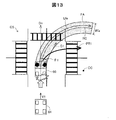
図13に示すように、飛び出しエリアFAは、自車両50が追突を受けたときに、旋回中心CCを中心とした円RCに沿って自車両50の車幅が描く領域として計算可能である。旋回円RCの半径Rは、例えば以下の式で算出できる。
R=L/sin(θ1) …(1)
ここで、Lは自車両50のホイールベースである。
飛び出しエリアFAの幅Wfaは、半径Rに沿って自車両50の車幅が描く領域の幅である。飛び出しエリアFAの長さLfaは、飛び出しエリアFAの中心が辿る曲線の長さであり、追突によって自車両50が進行して停止するまでの距離である。
As shown in FIG. 13, the pop-out area FA can be calculated as a region drawn by the vehicle width of the
R=L/sin(θ1) (1)
Here, L is the wheel base of the
The width Wfa of the projecting area FA is the width of the region drawn by the vehicle width of the
飛び出しエリアFAの半径Rは、上記(1)式で求めた値を基準として、第1操舵角θ1やその他のパラメータ(例えば後方車両61の車速や重量、自車両50の重量)を考慮して、実験的・経験的に補正した値に設定してもよい。飛び出しエリアFAの幅Wfaや、飛び出しエリアFAの長さLfaも同様である。なお、飛び出しエリアFAの長さLfaは、後方車両61の車速が高いほど大きく設定することが好ましい。飛び出しエリアFAの長さLfaは、交差点CSの歩道の端に達する位置までとしてもよい。
The radius R of the projecting area FA is based on the value obtained by the equation (1), and the first steering angle θ1 and other parameters (for example, the vehicle speed and weight of the
飛び出しエリアFAの半径Rと幅Wfaと長さLfaは、後方車両61の車速や重量、及び、自車両50の重量や第1操舵角θ1等の1つ以上のパラメータを入力とし、飛び出しエリアFAの半径Rと幅Wfaと長さLfaを出力とするマップやルックアップテーブルとして予め作成し、図示しない不揮発性メモリに格納しておくようにしてもよい。なお、飛び出しエリアFAの算出に使用する各種のパラメータは、支援情報取得部400の機能を利用して取得可能である。例えば、後方車両61の車速や重量は、車車間通信によって後方車両61から直接取得することが可能である。
The radius R, the width Wfa, and the length Lfa of the pop-out area FA are input with one or more parameters such as the vehicle speed and weight of the
図12のステップS420では、飛び出しエリアFA内で自車両50が他の物体と衝突する可能性があるか否かが判断される。衝突する可能性がある場合には、ステップS430において前方衝突条件が成立したものと判定される。一方、衝突する可能性が無い場合には、ステップS440において前方衝突条件が成立しないものと判定される。前方衝突の状況の一例は、図14に示されている。
In step S420 of FIG. 12, it is determined whether or not the
図14に示すように、自車両50の一時停止中に、前方から他の車両(「前方車両62」と呼ぶ)が交差点CSに近づきつつある状態を考える。図14において、
X1は、現在時刻(T=0)における後方車両61から自車両50までの距離、
V1は、後方車両61の車速、
X2は、現在時刻(T=0)における前方車両62から飛び出しエリアFAの外縁までの距離、
V2は、前方車両62の車速、
X3は、追突されてから前方車両62に衝突するまでの自車両50の推定移動距離である。
As shown in FIG. 14, consider a state in which another vehicle (referred to as a “
X1 is the distance from the
V1 is the vehicle speed of the
X2 is the distance from the
V2 is the vehicle speed of the
X3 is the estimated moving distance of the
このとき、例えば、以下の(2)式が成立する場合に、ステップS420の判断が肯定される。
−α<T2−(T1+T3)<β …(2)
ここで、
α,βは所定の時間マージン、
T1は、後方車両61による追突までの時間(T1=X1/V1)、
T2は、前方車両62が飛び出しエリアFAに到達するまでの時間(T2=X2/V2)、
T3は、自車両50が追突されてから前方車両62に衝突するまでの推定時間(T3=X3/(k×V2))、である。
なお、時間T3の算出に用いる係数kは、1未満の係数である。この係数kは、例えば自車両50の重量と、後方車両61の車速及び重量とのうちの1つ以上のパラメータに応じて決定されるようにしてもよく、あるいは、所定の一定値に設定してもよい。
At this time, for example, when the following expression (2) is satisfied, the determination in step S420 is affirmed.
-Α<T2-(T1+T3)<β (2)
here,
α and β are predetermined time margins,
T1 is the time (T1=X1/V1) until the rear-end collision with the
T2 is the time (T2=X2/V2) until the
T3 is an estimated time (T3=X3/(k×V2)) from the time when the
The coefficient k used to calculate the time T3 is less than 1. The coefficient k may be determined in accordance with one or more parameters of the weight of the
図15は、上記(2)式の意味を示している。ここでは、現在時刻(T=0)から時間T1経過後の時刻T1において自車両50に追突が発生し、更に時間T3経過後の時刻(T1+T3)に、飛び出しエリアFA内の地点PP(図14)に自車両50が到達すると推定される。この地点PPは、例えば、飛び出しエリアFAの中央を通る旋回円RCと、前方車両62の直進進路との交点位置である。一方、前方車両62は、現在時刻(T=0)から時間T2経過後の時刻T2に、飛び出しエリアFAに到達すると推定される。このとき、自車両50が地点PPに到達する時刻(T1+T3)と、前方車両62が飛び出しエリアFAに到達する時刻T2との差が所定の範囲内にあるときには、自車両50と前方車両62が衝突する可能性が高い。上述した(2)式は、このような衝突可能性の高い関係を示している。なお、αは、前方車両62が自車両50よりも先に飛び出しエリアFAを通り抜けるための時間マージンであり、βは、前方車両62が飛び出しエリアFAに到着するよりも先に自車両50が飛び出しエリアFAを通り抜けるための時間マージンである。時間マージンα,βは、いずれも正の値であり、例えば2〜3秒の範囲、又は5〜10秒の範囲の値に設定可能である。前方衝突が発生する可能性を安全側に見積もりたい場合には、時間マージンα,βが大きな値(例えば5〜10秒の範囲)に設定される。
FIG. 15 shows the meaning of the above equation (2). Here, a rear-end collision occurs in the
なお、図14の判定において、飛び出しエリアFA内で自車両50と衝突する可能性のある他の物体(前方車両62や人など)が停止している場合には、その速度V2はゼロである。この場合には、時間T2をゼロとして上記(2)式の判定を実行することができる。この際、他の物体が飛び出しエリアFA内に存在する場合にのみ、前方衝突条件が成立するものと判定するようにしても良い。
Note that, in the determination of FIG. 14, when another object (such as the
ステップS420で使用される各種のパラメータは、必要に応じて支援情報取得部400によって取得される。ステップS420で考慮される「他の物体」としては、車両や、歩行者、道路設備(信号機や道路標識)等が考慮される。なお、衝突可能性のある物体が歩行者や車両の場合には、衝突を避ける必要性がより高いので、ステップS420において歩行者又は車両のみを「他の物体」として考慮するようにしてもよい。
The various parameters used in step S420 are acquired by the support
図12に戻り、ステップS420の判断が肯定される場合には、前方の物体と衝突する可能性があるので、ステップS430において前方衝突条件が成立するものと判定される。一方、ステップS420の判断が否定される場合には、ステップS440において前方衝突条件が成立しないものと判定される。 Returning to FIG. 12, if the determination in step S420 is affirmative, there is a possibility of collision with an object in front, so it is determined in step S430 that the front collision condition is satisfied. On the other hand, if the determination in step S420 is negative, it is determined in step S440 that the front collision condition is not satisfied.
前方衝突条件が成立した場合には、図11のステップS230に進み、状況認知部220によって操舵角変更状況が認知される。一方、前方衝突条件が不成立の場合には、図9のステップS240に進み、操舵角変更状況は認知されない。この後の処理手順は、第2実施形態における図5のステップS130以降と同様である。
When the front collision condition is satisfied, the process proceeds to step S230 of FIG. 11, and the
なお、図11の手順において、ステップS300を省略し、ステップS220の後に直ちにステップS400における前方衝突条件の成立の有無を判断してもよい。この場合には、図13〜図15で説明した計算や予測において、後方車両61に関するパラメータ(速度や重量、距離)は、予め設定したデフォールト値を使用することが可能である。また、図11の手順において、ステップS300とステップS400の実行順序を入れ替えて、ステップS400をステップS300の前に実行するようにしてもよい。但し、図11に示すように、ステップS300の後にステップS400を実行するようにすれば、後方車両61に関するパラメータ(車速等)をステップS400の判定に利用できるので、飛び出しエリアFAをより精度良く計算することができるという利点がある。
Note that, in the procedure of FIG. 11, step S300 may be omitted, and immediately after step S220, it may be determined whether or not the front collision condition in step S400 is satisfied. In this case, the default values set in advance can be used for the parameters (speed, weight, distance) relating to the
以上のように、第4実施形態では、操舵角変更状況として、自車両50の走行条件に関する走行状況条件が成立することに加えて、後方車両に関する後方衝突条件が成立することと、前方の物体に関する前方衝突条件が成立することと、を含む操舵角変更状況を採用するので、後方衝突に起因する前方衝突の可能性がある場合にのみ、第1操舵角θ1から第2操舵角θ2に変更する。この結果、不要な操舵角の変更を行う可能性が第2実施形態よりも低下し、ドライバに不安感を与えることを更に抑制できる。
As described above, in the fourth embodiment, as the steering angle change situation, in addition to the traveling condition condition regarding the traveling condition of the
E. 第5実施形態:
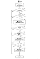
図16に示すように、第5実施形態は、第3実施形態の図10に示した後方衝突条件の詳細手順を変更したものである。第5実施形態では、後方衝突条件の判定手順が第3実施形態の手順(図10)と異なるが、図9で説明した操舵角変更処理の処理手順は第3実施形態と同じである。すなわち、第5実施形態では、図5の手順で電源接続変更処理の全体が実行され、図5のステップS120の判定が図9の詳細手順で実行され、図9のステップS300の判定が図16の詳細手順で実行される。なお、第5実施形態において、図5のステップS120の詳細手順として、図9で説明した第3実施形態の手順の代わりに、図11で説明した第4実施形態の手順を使用してもよい。
E. Fifth Embodiment:
As shown in FIG. 16, the fifth embodiment is a modification of the detailed procedure of the rear collision condition shown in FIG. 10 of the third embodiment. In the fifth embodiment, the procedure for determining the rear collision condition is different from the procedure (FIG. 10) of the third embodiment, but the processing procedure of the steering angle changing processing described in FIG. 9 is the same as that of the third embodiment. That is, in the fifth embodiment, the entire power supply connection changing process is executed by the procedure of FIG. 5, the determination of step S120 of FIG. 5 is executed by the detailed procedure of FIG. 9, and the determination of step S300 of FIG. It is executed in the detailed procedure of. Note that in the fifth embodiment, as the detailed procedure of step S120 of FIG. 5, the procedure of the fourth embodiment described in FIG. 11 may be used instead of the procedure of the third embodiment described in FIG. ..
図16が図10と異なる点は、ステップS310とステップS320の間に、ステップS311〜S315が追加されている点である。ステップS310では、後方車両61の車速が予め定められた閾値以上であり、かつ、自車両50と後方車両61との間の距離が第1所定値以下である、という条件が成立するか否かが判断される。このステップS310は、図10で説明したステップS310における「所定値」を「第1所定値」に変更したものであり、実質的に図10のステップS310と同じである。ステップS310の判断が否定される場合には、ステップS330において後方衝突条件が不成立と判定される。このときには、図9のステップS240に進み、操舵角変更状況は認知されない。一方、ステップS310の判断が肯定される場合には、ステップS311に進む。
16 is different from FIG. 10 in that steps S311 to S315 are added between step S310 and step S320. In step S310, whether the condition that the vehicle speed of the
ステップS311では、自動運転制御部210は、ドライバ警告部500に、後方車両61が自車両50に接近していることをドライバに警告させる。この警告は、例えば、警告音声の発生や、警告画像の表示によって行うことが可能である。このとき、後方車両61の車速が所定車速以上であることや、追突までの予想時間などの他の情報を併せて警告してもよい。
In step S311, the automatic
ステップS312では、自動運転制御部210は、ドライバ状態検出部510に、ドライバ(運転者)の状態を判定させる。具体的には、例えば、車内カメラ(図示省略)を用いてドライバの顔面を撮影し、撮影画面を分析してドライバの目、鼻、口の位置を特定する。次に、ドライバの目、鼻、口の位置に基づき、ドライバの焦点方向を特定する。ここで、「ドライバの焦点方向」とは、ドライバの注意が向いている方向を意味する。なお、焦点方向の特定のために、顔面認識を利用してドライバを識別し、予め設定されたドライバ固有の設定値を利用して焦点方向を決定してもよい。ドライバ状態検出部510は、ドライバの焦点方向を利用して、ドライバの注意深さ(注意散漫か否か)を判定することが可能である。また、ドライバ状態検出部510は、瞬目率(目の開閉の頻度)や、頭部の動きを注意深さの判定に利用しても良い。
In step S312, the automatic
ステップS313では、後方車両61の車速が予め定められた閾値以上であり、かつ、自車両50と後方車両61との間の距離が第2所定値以下である、という条件が成立するか否かが判断される。ステップS313で用いる距離の第2所定値は、ステップS311で用いた第1所定値よりも小さな値である。なお、車速の閾値はステップS311と同じ値を使用可能であるが、ステップS311と異なる値を使用してもよい。ステップS313の判断が否定される場合には、ステップS330において後方衝突条件が成立しないものと判定される。このときには、図9のステップS240に進み、操舵角変更状況は認知されない。一方、ステップS313の判断が肯定される場合には、後方車両61に追突される可能性があるため、ステップS314に進む。
In step S313, whether the condition that the vehicle speed of the
なお、ステップS313を省略して、ステップS312の後に直ちにステップS314を実行するようにしてもよい。また、ステップS312とステップS313の実行順序を逆にしてもよい。但し、ステップS312の後にステップS313を実行するようにすれば、後方車両61による追突に備えてより迅速な対応を行うことが可能である。一方、ステップS312の前にステップS313を実行するようにすれば、ステップS313の判断が否定されたときにドライバ状態の判定を行うことなく処理が終了するので、自動運転ECU200における演算負荷を低減できる。
Note that step S313 may be omitted and step S314 may be executed immediately after step S312. Further, the execution order of steps S312 and S313 may be reversed. However, if step S313 is executed after step S312, a quicker response can be provided in preparation for a rear-
ステップS314では、ドライバ状態検出部510によって検出されたドライバの状態が、ドライバが追突に対応可能な状態であるか否か、具体的には、後方車両61による自車両50への衝突に備えた操作をドライバが行うことが可能な状態であるか否か、が判断される。この判断は、ステップS312で検出されたドライバの状態を表す各種のパラメータ(ドライバの焦点方向や注意深さ)に基づいて総合的に行うことが可能である。ドライバが追突に対応可能な状態に無いと判定される場合には、ステップS320において、後方衝突条件が成立するものと判定される。一方、ドライバが追突に対応可能な状態であると判定される場合には、ステップS315に進む。
In step S314, whether or not the state of the driver detected by the driver
ステップS315では、自動運転制御部210が、自動運転の制御機能のうちの操舵角制御機能を含む少なくとも一部の制御機能をドライバに委譲する。自動運転の制御機能の主なものは、駆動部制御機能と、ブレーキ制御機能と、操舵角制御機能の3つである。すなわち、「自動運転の制御機能」とは、各制御装置310,320,330(図1)に指示値を送信して制御動作を行わせる機能である。追突の可能性がある場合に、ドライバの操作によって追突による被害を減少させるためには、前輪の方向を変更するための操舵角制御が重要であると考えられる。そこで、ステップS315では、自動運転の制御機能のうち、少なくとも操舵角制御機能をドライバに委譲することが好ましい。なお、ステップS315では、操舵角制御機能に加えて、駆動部制御機能とブレーキ制御機能の一方又は両方をドライバに委譲するようにしても良い。制御機能を委譲すると、ステップS330に進み、後方衝突条件が成立しないものと判定される。
In step S315, the automatic
後方衝突条件が成立した場合には、図9のステップS230に進み、状況認知部220によって操舵角変更状況が認知される。一方、後方衝突条件が不成立の場合には、図9のステップS240に進み、操舵角変更状況は認知されない。この後の処理手順は、第2実施形態における図5のステップS130以降と同様である。
When the rear collision condition is satisfied, the process proceeds to step S230 of FIG. 9 and the
以上のように、第5実施形態では、自動運転制御部210は、ドライバ状態検出部510によって検出されたドライバの状態が、後方車両61による自車両50への衝突に備えた操作をドライバが行うことが可能な状態である場合には、後方衝突条件が成立しないものと判定する。また、自動運転の制御機能のうちの操舵角制御機能を含む少なくとも一部の制御機能をドライバに委譲する。従って、ドライバが追突に対応可能な場合には、ドライバの操作によって追突による被害を減少させることができる。
As described above, in the fifth embodiment, the automatic
F. 第6実施形態:
図17に示すように、第6実施形態では、第1車線DL1を走行してきた自車両50が、第1車線DL1と合流する第2車線DL2に進入する状態を想定する。ここでは、自車両50の現在位置は、第1車線DL1と第2車線DL2の合流の手前の位置であり、自車両50は一時停止中又は徐行中である。自車両50の後方には、後方車両61が接近してくる可能性がある。また、第2車線DL2では、他の車両63が合流地点に向かって走行中である。このような他の車両63の走行状況は、例えば高度道路交通システム70や車車間通信を利用して他の車両63に関する情報を取得し、この情報を利用して状況認知部220が認知することが可能である。このような状況下では、自車両50が後方車両61に追突されると、第2車線DL2を走行する他の車両63と衝突する可能性がある。図18に示す操舵角変更状況の判定手順は、このような状況において衝突の影響を低減するために実行される。
F. Sixth Embodiment:
As shown in FIG. 17, in the sixth embodiment, it is assumed that the
図18に示すように、第6実施形態では、ステップS120(図5)の操舵角変更状況の判定の詳細手順が第2実施形態(図6)と異なるが、図5に示した電源接続変更処理の全体の手順は、第2実施形態と同じである。すなわち、第6実施形態では、図5の手順で電源接続変更処理の全体が実行され、図5のステップS120の判定が図18の詳細手順で実行される。 As shown in FIG. 18, in the sixth embodiment, the detailed procedure for determining the steering angle change status in step S120 (FIG. 5) differs from that in the second embodiment (FIG. 6), but the power supply connection change shown in FIG. The overall procedure of the process is the same as in the second embodiment. That is, in the sixth embodiment, the entire power supply connection changing process is executed in the procedure of FIG. 5, and the determination in step S120 of FIG. 5 is executed in the detailed procedure of FIG.
図18が図6と異なる点は、図6のステップS210,S220Rが省略されて、ステップS200とステップS230の間に、ステップS215,S300,S500が追加されている点である。ステップS215では、自車両50が第1車線DL1と第2車線DL2の合流の手前の位置であるか否かが判断される。この判断は、例えば、自車両50の現在位置が、車線の合流地点から所定の範囲内にあるか否かによって行われる。ステップS215の判断が否定されると、ステップS240に進み、操舵角変更状況は認知されない。一方、ステップS215の判断が肯定されると、ステップS300において、後方衝突条件が成立するか否かが判断される。このステップS300は、第3実施形態で説明した図10の手順、又は、第5実施形態で説明した図16の手順で実行される。後方衝突条件が不成立の場合には、ステップS240に進み、操舵角変更状況は認知されない。一方、後方衝突条件が成立する場合には、ステップS500において、予め定められた合流衝突条件が成立するか否かが判断される。
18 is different from FIG. 6 in that steps S210 and S220R of FIG. 6 are omitted and steps S215, S300, and S500 are added between steps S200 and S230. In step S215, it is determined whether or not the
ステップS500における合流衝突条件の判断は、例えば、自車両50が第1操舵角θ1の状態で追突を受けたと仮定した場合に、追突により前方に飛び出した自車両50が通過する領域を飛び出しエリアとして算出し、その飛び出しエリア内で自車両50が第2車線DL2を走行してくる他の車両63と衝突する可能性があるか否か、を決定することによって判断される。この判断は、第4実施形態において図13〜図15を用いて説明した手法に準じて行うことが可能なので、ここではその詳細な説明は省略する。
In the determination of the merge collision condition in step S500, for example, when it is assumed that the
合流衝突条件が成立する場合には、ステップS230に進み、状況認知部220によって操舵角変更状況が認知される。一方、合流衝突条件が成立しない場合には、ステップS240に進み、操舵角変更状況は認知されない。なお、図18の手順において、ステップS300を省略し、ステップS215の後に直ちにステップS500における合流衝突条件の成立の有無を判断してもよい。
When the merge collision condition is satisfied, the process proceeds to step S230, and the
なお、第6実施形態において、操舵角変更状況が認知された場合に採用される第2操舵角θ2は、図17に例示するように、第1操舵角θ1よりも、自車両50が第2車線DL2から遠ざかる方向に進行するように設定されることが好ましい。こうすれば、合流時の衝突の可能性を更に低減できる。 Note that, in the sixth embodiment, the second steering angle θ2 that is adopted when the steering angle change situation is recognized is, as illustrated in FIG. It is preferable to set the vehicle so that it travels away from the lane DL2. By doing so, the possibility of collision at the time of merging can be further reduced.
以上のように、第6実施形態では、自車両50の現在位置が第1車線DL1と第2車線DL2の合流の手前の位置である場合に、自車両50が追突を受けて他の車両63と衝突する可能性があることを示す合流衝突条件を満たした場合に、自車両50の操舵角を走行予定経路に沿った第1操舵角θ1から第2操舵角θ2に変更する。従って、自車両50が第1車線DL1と第2車線DL2の合流の手前の位置において一時停止中又は徐行中であるときに追突された場合にも、第1操舵角θ1に従って第2車線DL2に押し出される可能性を低減できる。この結果、追突による影響を緩和することが可能である。
As described above, in the sixth embodiment, when the current position of the
G. 第7実施形態:
図19に示すように、第7実施形態では、第1車線DL1を走行してきた自車両50が、車両の走行のための道路(車線)では無いスペース(「非車線スペース」と呼ぶ)に移動する状態を想定する。この例では、非車線スペースは、店舗STの前の歩道PLである。なお、非車線スペースとしては、歩道の他に、駐車場などの各種のスペースを想定可能である。自車両50の現在位置は、第1車線DL1から非車線スペースとしての歩道PLに移動する手前の位置であり、自車両50は一時停止中又は徐行中である。自車両50の後方には、後方車両61が接近してくる可能性がある。また、歩道PLには、人や自転車のような他の物体64が存在する可能性がある。この物体64は、自車両50が第1車線DL1から非車線スペースとしての歩道PLに移動する経路に進行可能である。このような他の物体64の状況は、例えば前方検出装置410を用いて検出し、その検出結果を利用して前方認知部224が認知することが可能である。このような状況下では、自車両50が後方車両61に追突されると、歩道PLにいる他の物体64と衝突する可能性がある。図20に示す操舵角変更状況の判定手順は、このような状況において衝突の影響を低減するために実行される。
G. Seventh embodiment:
As shown in FIG. 19, in the seventh embodiment, the
図20に示す第7実施形態における操舵角変更状況の判定手順は、図18に示した第6実施形態のステップS215とステップS500を、ステップS216とステップS600にそれぞれ置き換えたものに相当する。図5に示した電源接続変更処理の全体の手順は、第2実施形態と同じである。すなわち、第7実施形態では、図5の手順で電源接続変更処理の全体が実行され、図5のステップS120の判定が図20の詳細手順で実行される。 The procedure for determining the steering angle change status in the seventh embodiment shown in FIG. 20 corresponds to the steps S215 and S500 of the sixth embodiment shown in FIG. 18 replaced with steps S216 and S600, respectively. The overall procedure of the power supply connection change process shown in FIG. 5 is the same as that of the second embodiment. That is, in the seventh embodiment, the entire power supply connection changing process is executed in the procedure of FIG. 5, and the determination in step S120 of FIG. 5 is executed in the detailed procedure of FIG.
ステップS216では、自車両50の現在位置が、非車線スペースへの移動の手前の位置であるか否かが判断される。ステップS216の判断が否定されると、ステップS240に進み、操舵角変更状況は認知されない。一方、ステップS216の判断が肯定されると、ステップS300において、後方衝突条件が成立するか否かが判断される。このステップS300は、第3実施形態で説明した図10の手順、又は、第5実施形態で説明した図16の手順で実行される。後方衝突条件が不成立の場合には、ステップS240に進み、操舵角変更状況は認知されない。一方、後方衝突条件が成立する場合には、ステップS600において、予め定められた衝突条件が成立するか否かが判断される。
In step S216, it is determined whether or not the current position of the
ステップS600における衝突条件の判断は、例えば、自車両50が第1操舵角θ1の状態で追突を受けたと仮定した場合に、追突により前方に飛び出した自車両50が通過する領域を飛び出しエリアとして算出し、その飛び出しエリア内で自車両50が他の物体64と衝突する可能性があるか否か、を決定することによって判断される。この判断は、第4実施形態において図13〜図15を用いて説明した手法に準じて行うことが可能なので、ここではその詳細な説明は省略する。
In the determination of the collision condition in step S600, for example, when it is assumed that the
衝突条件が成立する場合には、ステップS230に進み、状況認知部220によって操舵角変更状況が認知される。一方、衝突条件が成立しない場合には、ステップS240に進み、操舵角変更状況は認知されない。なお、図20の手順において、ステップS300を省略し、ステップS216の後に直ちにステップS600における衝突条件の成立の有無を判断してもよい。
If the collision condition is satisfied, the process proceeds to step S230, and the
なお、第7実施形態において、操舵角変更状況が認知された場合に採用される第2操舵角θ2は、図19に例示するように、第2操舵角θ2で示される前輪の方向が、第1操舵角θ1で示される方向よりも、第1車線DL1の車線直進方向DRsに近づくように設定されることが好ましい。こうすれば、他の物体64との衝突の可能性を更に低減できる。
Note that, in the seventh embodiment, the second steering angle θ2 adopted when the steering angle change situation is recognized is, as illustrated in FIG. 19, the direction of the front wheels indicated by the second steering angle θ2 is It is preferable to set so as to be closer to the lane straight traveling direction DRs of the first lane DL1 than the direction indicated by the first steering angle θ1. By doing so, the possibility of collision with another
以上のように、第7実施形態では、自車両50の現在位置が、車両の走行のための車線から非車線スペースに移動する手前の位置であり、かつ、自車両50が追突を受けて他の物体64と衝突する可能性があることを示す衝突条件を満たした場合に、走行予定経路に沿った第1操舵角θ1から第2操舵角θ2に変更する。従って、自車両50が非車線スペースに移動する手前の位置において一時停止中又は徐行中であるときに追突された場合にも、第1操舵角θ1に従って自車両50が飛び出すことによって、他の物体64と衝突する可能性を低減できる。この結果、追突による影響を緩和することが可能である。
As described above, in the seventh embodiment, the current position of the
H. 第8実施形態:
図21に示すように、第8実施形態における電源接続変更処理の手順は、図3のステップS20とステップS30の間にステップS22,S24を追加したものであり、これ以外の処理は第1実施形態と同じである。ステップS20において衝突の可能性があると判定されると、ステップS22では、状況認知部220が、自動運転制御部210が採用し得る複数の自動運転動作に関するコストを算出し、コストが最小となる自動運転動作を決定する。複数の自動運転動作としては、駆動部指示値とブレーキ指示値と操舵角指示値の様々な組み合わせを採用可能である。各自動運転動作のコストは、例えば、自車両50と他の物体の相対速度や、構造、重量、衝突方向、他の物体の種類(人間を含むか否か)、及び、衝突部位等の複数のパラメータを利用したシミュレーションを行うことによって算出することが可能である。あるいは、これらのパラメータを入力とし、コストを出力とするマップやルックアップテーブルを利用してコストを求めても良い。「コスト」とは、衝突の結果が重大と評価されるほど大きな値を示す指標であり、経済的コストに限らず、精神的コストを考慮して総合的に決定される。例えば、他の物体が人間を含む場合には、精神的コストが大きく、その自動運転動作のコストも大きくなる傾向にある。なお、コストの算出に使用される各種のパラメータは、支援情報取得部400によって取得可能である。コストが最小の自動運転動作が決定されると、その自動運転動作が採用されて自車両50の制御が実行される。また、その自動運転動作において他の物体が衝突すると予期される自車両50の部位も決定される。
H. Eighth Embodiment:
As shown in FIG. 21, the procedure of the power supply connection changing process in the eighth embodiment is such that steps S22 and S24 are added between step S20 and step S30 in FIG. 3, and other processes are performed in the first embodiment. It is the same as the form. When it is determined in step S20 that there is a possibility of collision, in step S22, the
ステップS24では、ステップS22で採用した自動運転動作によって衝突が回避できるか否かが判断される。衝突が回避できる場合には、図21の処理が終了する。一方、衝突が回避できない場合にはステップS30に進み、電源回路620が緊急接続状態に切り替えられる。このステップS30以降の処理は図3に示した第1実施形態と同様である。
In step S24, it is determined whether the collision can be avoided by the automatic driving operation adopted in step S22. If the collision can be avoided, the process of FIG. 21 ends. On the other hand, if the collision cannot be avoided, the process proceeds to step S30, and the
このように、第8実施形態では、車両が他の物体と衝突する可能性がある場合に、自動運転制御部210が採用し得る複数の自動運転動作に関するコストを状況認知部220が算出し、コストが最小となる自動運転動作を採用する。従って、衝突が避けられない場合にも、衝突によるコストが最小になるように自動運転を実行することができる。また、採用した自動運転動作において衝突が回避できない場合には、状況認知部220が他の物体が衝突すると予期される破損予期電源を認知し、自動運転制御部210がその破損予期電源を特定補機から切り離すとともに、破損予期電源以外の1つ以上の電源を特定補機に接続するように電源制御ECU610に指示を行う。従って、衝突が発生したとしても、特定補機に電力を継続して供給することが可能となり、破損予期電源の破損や特定補機の電源喪失によって二次被害が発生する可能性を低減できる。
As described above, in the eighth embodiment, when the vehicle may collide with another object, the
I. 変形例
本発明は上述した実施形態やその変形例に限られるものではなく、その要旨を逸脱しない範囲において種々の態様において実施することが可能であり、例えば次のような変形も可能である。
I. Modifications The present invention is not limited to the above-described embodiments and modifications thereof, and can be implemented in various modes without departing from the scope of the invention, and for example, the following modifications are also possible. is there.
(1)上記第2〜第5実施形態では、後方車両61は自車両50と同じ車線を走行する車両であったが、後方車両61が隣の車線を走行する車両であっても良い。図22〜図24には、自車両50の車線DLaの隣の車線DLbを走行する後方車両61が自車両50に衝突する例を示している。図22は、隣の車線DLbを直進する後方車両61がその車線DLbをはみ出して走行して、自車両50に衝突してしまう例である。図23は、自車両50がその車線DLaからはみ出した状態で一時停止している場合に、隣の車線DLbを直進する後方車両61が自車両50に衝突してしまう例である。図24は、自車両50が少し旋回し、その左側後方部が隣の車線DLbにはみ出した状態で停止している場合に、隣の車線DLbを直進する後方車両61が自車両50に衝突してしまう例である。これらの場合にも、自車両50の操舵角を、走行予定経路PR1に沿った第1操舵角θ1からこれとは異なる第2操舵角θ2にしておくことで、自車両50が対向車線側へ押し出されることを抑制できる。
(1) In the second to fifth embodiments, the
なお、図22及び図23の例に示すように、交差点CS内にいる自車両50は傾いていない場合もある。そして、自車両50は、まだハンドルを切る前の状態である場合がある。この場合には、第1操舵角θ1は、車線DLaの直進方向に沿った操舵角となり、ニュートラルな状態にある。その場合においても、隣の車線DLbを走行する後方車両61の部分衝突による対向車線への押し出しに備えて、車輪の方向を、ニュートラル方向を挟んで第1操舵角θ1が示す方向とは反対側の方向となるように第2操舵角θ2を設定すれば、対向車線への押し出しを抑制することができる。
As shown in the examples of FIGS. 22 and 23, the
(2)上記各実施形態では、前輪をステアリング操作している車両について説明したが、後輪をステアリング操作する車両にも、本発明は適用できる。 (2) In each of the above embodiments, the vehicle in which the front wheels are steered has been described, but the present invention is also applicable to a vehicle in which the rear wheels are steered.
(3)上記各実施形態で説明したステップの一部を適宜省略したり、実行順序を変更したりすることが可能である。また、各実施形態を任意に組み合わせることが可能である。例えば、第2〜第5実施形態で説明した交差点における処理のいずれか一つと、第6実施形態で説明した合流地点における処理と、第7実施形態で説明した非車線スペースへの進入時における処理Tと、のうちの任意の2つ以上の処理を、同一の自動運転制御システムで実現するようにしてもよい。 (3) It is possible to appropriately omit some of the steps described in each of the above-described embodiments or change the execution order. Further, the respective embodiments can be arbitrarily combined. For example, any one of the processing at the intersection described in the second to fifth embodiments, the processing at the confluence described in the sixth embodiment, and the processing at the time of entering the non-lane space described in the seventh embodiment. Any two or more processes of T and T may be realized by the same automatic driving control system.
50…自車両、52…前輪、60…他車両、61…後方車両、62…前方車両、63…他車両、64…物体、70…高度道路交通システム、100…自動運転制御システム、200…自動運転ECU、210…自動運転制御部、220…状況認知部、222…走行状況認知部、224…前方認知部、226…後方認知部、300…車両制御部、310…駆動部制御装置、320…ブレーキ制御装置、330…操舵角制御装置(操舵角制御部)、340…一般センサ類、342…車速センサ、344…操舵角センサ、400…支援情報取得部、410…前方検出装置、420…後方検出装置、430…GPS装置、440…ナビゲーション装置、450…無線通信装置、500…ドライバ警告部、510…ドライバ状態検出部、520…警告装置、600…電源部、610…電源制御ECU(リレー制御装置)、620…電源回路、621…第1電源,622…第2電源、625…電源配線、630…リレー装置、631…第1リレー、632…第2リレー 50... Own vehicle, 52... Front wheel, 60... Other vehicle, 61... Rear vehicle, 62... Forward vehicle, 63... Other vehicle, 64... Object, 70... Intelligent transportation system, 100... Automatic driving control system, 200... Automatic Driving ECU, 210... Automatic driving control unit, 220... Situation recognition unit, 222... Running situation recognition unit, 224... Front recognition unit, 226... Rear recognition unit, 300... Vehicle control unit, 310... Drive unit control device, 320... Brake control device, 330... Steering angle control device (steering angle control unit), 340... General sensors, 342... Vehicle speed sensor, 344... Steering angle sensor, 400... Support information acquisition unit, 410... Front detection device, 420... Rear Detection device, 430... GPS device, 440... Navigation device, 450... Wireless communication device, 500... Driver warning unit, 510... Driver state detection unit, 520... Warning device, 600... Power supply unit, 610... Power supply control ECU (relay control) Device), 620... power supply circuit, 621... first power supply, 622... second power supply, 625... power supply wiring, 630... relay device, 631... first relay, 632... second relay
Claims (13)
前記自車両に設置され、それぞれ、前記自車両の特定補機(200,220,320,330,340,410,420,610)に対して電力を供給可能な複数の電源(621,622)と、
前記特定補機に対する前記複数の電源の接続状態を変更するリレー装置(630)と、
前記リレー装置を制御するリレー制御装置(610)と、
前記走行予定経路における前記自車両の状況と、前記自車両の周辺における他の物体の状況とを認知可能な状況認知部(220)と、
前記リレー制御装置に前記複数の電源の接続状態を指示し自動運転の制御を行う自動運転制御部(210)と、
を備え、
前記状況認知部は、前記自動運転中における前記自車両の前記他の物体と衝突する衝突確率が所定閾値以上であること、および、前記衝突確率が前記所定閾値以上である場合に、前記複数の電源のうち、前記他の物体との衝突により破損が発生すると予期される破損予期電源を認知し、
前記自動運転制御部は、前記衝突確率が前記所定閾値以上である場合に、前記破損予期電源を前記特定補機から切り離すとともに、前記複数の電源のうち前記破損予期電源でない電源を前記特定補機に接続するよう、前記リレー制御装置に指示を行い、
前記状況認知部は、前記衝突確率が前記所定閾値以上であることを認知した場合に、前記自動運転制御部が採用し得る複数の自動運転動作に関するコストを算出し、前記コストが最小となる自動運転動作を採用するとともに、当該採用した自動運転動作において前記他の物体が衝突すると予期される前記自車両の部位を決定する、自動運転制御システム。 An automatic driving control system (100) for executing automatic driving for causing a host vehicle (50) to travel along a planned travel route,
A plurality of power sources (621, 622) installed in the own vehicle and capable of supplying electric power to the specific auxiliary devices (200, 220, 320, 330, 340, 410, 420, 610) of the own vehicle, respectively. ,
A relay device (630) for changing the connection state of the plurality of power sources to the specific auxiliary device;
A relay control device (610) for controlling the relay device;
A situation recognition unit (220) capable of recognizing the situation of the own vehicle in the planned traveling route and the situation of other objects around the own vehicle;
An automatic operation control unit (210) for instructing the relay control device about the connection state of the plurality of power sources and controlling automatic operation;
Equipped with
The situation recognition unit, the collision probability of colliding with the other object of the own vehicle during the automatic driving is a predetermined threshold value or more, and, if the collision probability is the predetermined threshold value or more, the plurality of Among the power supplies, recognize the expected damage power supply that is expected to be damaged due to collision with the other object,
When the collision probability is equal to or higher than the predetermined threshold value, the automatic operation control unit disconnects the damage expected power supply from the specific auxiliary device and selects a power supply that is not the damage expected power supply from the plurality of power supplies as the specific auxiliary device. to connect to, have rows instruction to the relay control unit,
When the situation recognition unit recognizes that the collision probability is equal to or higher than the predetermined threshold value, the situation recognition unit calculates costs related to a plurality of automatic driving operations that can be adopted by the automatic driving control unit, and the cost is automatically minimized. An automatic driving control system that adopts a driving operation and determines a part of the vehicle that is expected to collide with the other object in the adopted automatic driving operation .
前記自動運転制御部は、前記衝突確率が前記所定閾値以上であることを前記状況認知部が認知した場合に、前記複数の電源のうちの2つ以上の電源が前記特定補機に並列に接続された状態である通常接続状態から、前記破損予期電源を前記特定補機から切り離すとともに前記複数の電源のうち前記破損予期電源でない電源を前記特定補機に接続した緊急接続状態に変更するよう、前記リレー制御装置に指示を行う、自動運転制御システム。 The automatic driving control system according to claim 1,
When the situation recognition unit recognizes that the collision probability is equal to or higher than the predetermined threshold, the automatic driving control unit connects two or more power sources of the plurality of power sources in parallel to the specific auxiliary device. From the normal connection state which is the state in which the expected damage power supply is disconnected from the specific auxiliary machine and the power supply which is not the expected damage power supply of the plurality of power supplies is changed to the emergency connection state in which the specific auxiliary machine is connected. An automatic driving control system for giving an instruction to the relay control device.
前記特定補機は、前記自動運転制御部と、前記状況認知部と、ブレーキ制御装置と、操舵角制御装置と、のうちの少なくとも一つを含む、自動運転制御システム。 The automatic driving control system according to claim 1 or 2,
The said specific auxiliary machine is an automatic driving control system containing at least one of the said automatic driving control part, the said situation recognition part, a brake control device, and a steering angle control device.
前記自車両の車輪(52)の操舵角を制御する操舵角制御部(330)を備え、
前記自動運転制御部は、前記破損予期電源を前記特定補機から切り離すとともに、前記複数の電源のうち前記破損予期電源でない電源を前記特定補機に接続するよう、前記リレー制御装置に指示を行った後に、前記状況認知部が前記自車両の速度が所定値以下であること、という条件が成立することを含む予め定められた操舵角変更状況を認知した場合に、前記操舵角制御部に対し指示する前記操舵角を、前記走行予定経路に沿った第1操舵角(θ1)から前記第1操舵角と異なる第2操舵角(θ2)に変更する、自動運転制御システム。 The automatic driving control system according to any one of claims 1 to 3, further comprising:
A steering angle control unit (330) for controlling the steering angle of the wheels (52) of the vehicle,
The automatic driving control unit instructs the relay control device to disconnect the expected damage power supply from the specific auxiliary device and connect a power supply that is not the expected damage power supply to the specific auxiliary device among the plurality of power supplies. After that, when the situation recognition unit recognizes a predetermined steering angle change situation including the condition that the speed of the host vehicle is equal to or less than a predetermined value, the steering angle control unit is notified to the steering angle control unit. An automatic driving control system for changing the instructed steering angle from a first steering angle (θ1) along the planned travel route to a second steering angle (θ2) different from the first steering angle.
前記操舵角変更状況は、更に、前記自車両の現在位置が交差点の中央から所定の範囲内に存在すること、という条件が成立することを含む、自動運転制御システム。 The automatic driving control system according to claim 4 ,
The automatic driving control system further includes that the steering angle change situation further satisfies a condition that the current position of the host vehicle is within a predetermined range from the center of the intersection.
前記第1操舵角は、前記自車両の車輪の方向を前記交差点における車線直進方向と異なる方向に向ける角度であり、
前記第2操舵角は、前記第1操舵角よりも前記車輪の方向を前記車線直進方向に近い方向に変更する角度である、自動運転制御システム。 The automatic driving control system according to claim 5 ,
The first steering angle is an angle that directs the direction of the wheels of the host vehicle to a direction different from the straight lane direction at the intersection,
The said 2nd steering angle is an automatic driving control system which is an angle which changes the direction of the said wheel to the direction near the said lane straight ahead direction rather than the said 1st steering angle.
前記第2操舵角は、前記車輪の方向を、前記自車両の前後方向に平行なニュートラル方向とする角度、又は、前記ニュートラル方向を挟んで前記第1操舵角が示す方向とは反対側の方向とする角度である、自動運転制御システム。 The automatic driving control system according to claim 6 ,
The second steering angle is an angle that makes the direction of the wheel a neutral direction parallel to the front-rear direction of the host vehicle, or a direction opposite to the direction indicated by the first steering angle across the neutral direction. The automatic driving control system, which is the angle.
前記状況認知部は、更に、前記自車両の後方を走行する後方車両(61)の近接状況を認知可能であり、
前記操舵角変更状況は、更に、
前記後方車両の近接状況が予め設定された後方衝突条件を満たすことを含む、自動運転制御システム。 The automatic driving control system according to any one of claims 4 to 7 ,
The situation recognition unit can further recognize a proximity situation of a rear vehicle (61) traveling behind the own vehicle,
The steering angle change status is
An automatic driving control system including that the proximity situation of the rear vehicle satisfies a preset rear collision condition.
前記状況認知部は、更に、前記自車両の前方にある前方物体(62)を認知可能であり、
前記操舵角変更状況は、更に、
前記自車両が前記後方車両の追突を受けて前記前方物体と衝突する可能性があることを示す前方衝突条件を満たすことを含む、自動運転制御システム。 The automatic driving control system according to claim 8 ,
The situation recognition unit is further capable of recognizing a front object (62) in front of the own vehicle,
The steering angle change status is
An automatic driving control system including satisfying a frontal collision condition indicating that the host vehicle may collide with the front object after being hit by the rear vehicle.
前記自車両のドライバの状態を検出するドライバ状態検出部(510)を備え、
前記ドライバ状態検出部によって検出された前記ドライバの状態が、前記後方車両による前記自車両への衝突に備えた操作を前記ドライバが行うことが可能な状態である場合には、前記状況認知部が前記後方衝突条件が成立しないものと判定するとともに、前記自動運転制御部が前記自動運転の制御機能のうちの操舵角制御機能を含む少なくとも一部の制御機能を前記ドライバに委譲する、自動運転制御システム。 The automatic driving control system according to claim 8 or 9 , further comprising:
A driver state detection unit (510) for detecting the state of the driver of the own vehicle;
When the driver's state detected by the driver state detection unit is a state in which the driver can perform an operation in preparation for a collision of the rear vehicle with the own vehicle, the situation recognition unit Automatic driving control in which it is determined that the rear collision condition is not satisfied, and the automatic driving control unit transfers at least a part of control functions including a steering angle control function of the automatic driving control functions to the driver. system.
前記自車両が位置する第1車線(DL1)と合流する第2車線(DL2)が存在し、前記自車両の現在位置が前記第1車線と前記第2車線の合流の手前の位置である場合に、
前記状況認知部は、更に、前記第2車線を走行する他の車両(63)の走行状況の認知を行うことが可能であり、
前記操舵角変更状況は、更に、
前記自車両が追突を受けて前記他の車両と衝突する可能性があることを示す合流衝突条件を満たすことを含む、自動運転制御システム。 The automatic driving control system according to claim 4 ,
There is a second lane (DL2) that merges with the first lane (DL1) in which the host vehicle is located, and the current position of the host vehicle is a position before the merging of the first lane and the second lane. To
The situation recognition unit can further recognize the traveling situation of another vehicle (63) traveling in the second lane,
The steering angle change status is
An automatic driving control system including satisfying a merged collision condition indicating that the own vehicle may undergo a rear-end collision and collide with the other vehicle.
前記自車両の現在位置が、車両の走行のための車線から非車線スペースに移動する手前の位置である場合に、
前記状況認知部は、更に、前記自車両が前記車線から前記非車線スペースに移動する経路に進行可能な他の物体(64)を認知可能であり、
前記操舵角変更状況は、更に、
前記自車両が追突を受けて前記他の物体とが衝突する可能性があることを示す衝突条件を満たすことを含む、自動運転制御システム。 The automatic driving control system according to claim 4 ,
When the current position of the own vehicle is a position before moving to a non-lane space from the lane for traveling of the vehicle,
The situation recognition unit is further capable of recognizing another object (64) capable of traveling on a route in which the vehicle travels from the lane to the non-lane space,
The steering angle change status is
An automatic driving control system including satisfying a collision condition indicating that the own vehicle may undergo a rear-end collision and collide with the other object.
前記自動運転制御部は、前記自車両の停止中に前記操舵角制御部に前記第1操舵角から前記第2操舵角への変更を行わせた場合に、前記自車両の走行を開始する際に前記自車両の車輪に駆動力が付与されるまで前記操舵角制御部に前記第2操舵角を保持させる、自動運転制御システム。 The automatic driving control system according to any one of claims 4 to 12 ,
The automatic driving control unit starts traveling of the host vehicle when the steering angle control unit changes the first steering angle to the second steering angle while the host vehicle is stopped. An automatic driving control system for causing the steering angle control unit to maintain the second steering angle until a driving force is applied to the wheels of the vehicle.
Priority Applications (4)
| Application Number | Priority Date | Filing Date | Title |
|---|---|---|---|
| JP2017095448A JP6711312B2 (en) | 2017-05-12 | 2017-05-12 | Vehicle automatic driving control system |
| CN201880031369.5A CN110621551A (en) | 2017-05-12 | 2018-02-21 | Automatic driving control system for vehicle |
| PCT/JP2018/006184 WO2018207425A1 (en) | 2017-05-12 | 2018-02-21 | Autonomous driving control system for vehicles |
| US16/681,011 US20200079366A1 (en) | 2017-05-12 | 2019-11-12 | Automatic driving control system for vehicle |
Applications Claiming Priority (1)
| Application Number | Priority Date | Filing Date | Title |
|---|---|---|---|
| JP2017095448A JP6711312B2 (en) | 2017-05-12 | 2017-05-12 | Vehicle automatic driving control system |
Publications (3)
| Publication Number | Publication Date |
|---|---|
| JP2018192826A JP2018192826A (en) | 2018-12-06 |
| JP2018192826A5 JP2018192826A5 (en) | 2019-09-19 |
| JP6711312B2 true JP6711312B2 (en) | 2020-06-17 |
Family
ID=64104943
Family Applications (1)
| Application Number | Title | Priority Date | Filing Date |
|---|---|---|---|
| JP2017095448A Active JP6711312B2 (en) | 2017-05-12 | 2017-05-12 | Vehicle automatic driving control system |
Country Status (4)
| Country | Link |
|---|---|
| US (1) | US20200079366A1 (en) |
| JP (1) | JP6711312B2 (en) |
| CN (1) | CN110621551A (en) |
| WO (1) | WO2018207425A1 (en) |
Families Citing this family (11)
| Publication number | Priority date | Publication date | Assignee | Title |
|---|---|---|---|---|
| JP7024667B2 (en) * | 2018-08-30 | 2022-02-24 | トヨタ自動車株式会社 | Vehicle power system |
| JP7247499B2 (en) * | 2018-09-20 | 2023-03-29 | いすゞ自動車株式会社 | Vehicle monitoring device |
| CN111086508A (en) * | 2018-10-24 | 2020-05-01 | 罗伯特·博世有限公司 | Method for automatically avoiding or reducing collision, control system, storage medium and automobile |
| CN111376854A (en) * | 2018-12-28 | 2020-07-07 | 观致汽车有限公司 | Power supply device for advanced driver assistance system of motor vehicle |
| JP7190946B2 (en) * | 2019-03-20 | 2022-12-16 | 三菱重工エンジニアリング株式会社 | Power supply, automatic steering vehicle, and power supply method |
| JP7268612B2 (en) * | 2020-01-20 | 2023-05-08 | トヨタ自動車株式会社 | Driving support device |
| CA3168740C (en) * | 2020-02-21 | 2023-08-01 | Joel Pazhayampallil | Method for object avoidance during autonomous navigation |
| US20210341926A1 (en) * | 2020-04-29 | 2021-11-04 | Gm Cruise Holdings Llc | Dynamic tire rotation during collision |
| KR20220022381A (en) * | 2020-08-18 | 2022-02-25 | 현대자동차주식회사 | Vehicle and control method thereof |
| JP7400754B2 (en) | 2021-02-24 | 2023-12-19 | トヨタ自動車株式会社 | Remote support system and remote support method |
| CN114771652A (en) * | 2022-04-15 | 2022-07-22 | 江铃汽车股份有限公司 | Automatic driving steering control method and system |
Family Cites Families (14)
| Publication number | Priority date | Publication date | Assignee | Title |
|---|---|---|---|---|
| JP2006062419A (en) * | 2004-08-24 | 2006-03-09 | Toyota Motor Corp | Vehicular controlling device |
| JP2006199134A (en) * | 2005-01-20 | 2006-08-03 | Mazda Motor Corp | Vehicular steering device |
| JP2006306270A (en) * | 2005-04-28 | 2006-11-09 | Nissan Motor Co Ltd | Collision control device for vehicle |
| JP2007190977A (en) * | 2006-01-17 | 2007-08-02 | Toyota Motor Corp | Vehicle control device |
| JP4245059B2 (en) * | 2007-02-27 | 2009-03-25 | 株式会社デンソー | In-vehicle emergency call device |
| JP2012045984A (en) * | 2010-08-24 | 2012-03-08 | Mitsubishi Motors Corp | Collision reducing device |
| US8698639B2 (en) * | 2011-02-18 | 2014-04-15 | Honda Motor Co., Ltd. | System and method for responding to driver behavior |
| CN102275557B (en) * | 2011-04-27 | 2013-05-22 | 奇瑞汽车股份有限公司 | Vehicle collision safety control system and control method thereof |
| JP5590231B2 (en) * | 2011-05-12 | 2014-09-17 | トヨタ自動車株式会社 | Vehicle collision detection device |
| JP6135491B2 (en) * | 2013-12-16 | 2017-05-31 | 株式会社オートネットワーク技術研究所 | Automotive power supply |
| JP6451211B2 (en) * | 2014-10-30 | 2019-01-16 | 日産自動車株式会社 | Travel control device |
| JP6115579B2 (en) * | 2015-02-16 | 2017-04-19 | トヨタ自動車株式会社 | Collision avoidance device |
| US20170001636A1 (en) * | 2015-07-01 | 2017-01-05 | Delphi Technologies, Inc. | Automated Vehicle Response To Imminent Rear-End Collision |
| JP6494030B2 (en) * | 2015-07-13 | 2019-04-03 | 株式会社テクトム | Connection unit for OBE |
-
2017
- 2017-05-12 JP JP2017095448A patent/JP6711312B2/en active Active
-
2018
- 2018-02-21 CN CN201880031369.5A patent/CN110621551A/en active Pending
- 2018-02-21 WO PCT/JP2018/006184 patent/WO2018207425A1/en active Application Filing
-
2019
- 2019-11-12 US US16/681,011 patent/US20200079366A1/en not_active Abandoned
Also Published As
| Publication number | Publication date |
|---|---|
| WO2018207425A1 (en) | 2018-11-15 |
| JP2018192826A (en) | 2018-12-06 |
| US20200079366A1 (en) | 2020-03-12 |
| CN110621551A (en) | 2019-12-27 |
Similar Documents
| Publication | Publication Date | Title |
|---|---|---|
| JP6711312B2 (en) | Vehicle automatic driving control system | |
| CN109641591B (en) | Automatic driving device | |
| JP7069518B2 (en) | Vehicle control unit | |
| CN110546461B (en) | Driving control method and driving control device | |
| JP6859931B2 (en) | Autonomous driving system | |
| RU2760046C1 (en) | Driving assistance and driving assistance device | |
| US11584375B2 (en) | Vehicle control device, vehicle control method, and storage medium | |
| JP2019043169A (en) | Vehicle control system, vehicle control method and program | |
| US20140058579A1 (en) | Driving assist device and driving assist method | |
| JP7115184B2 (en) | Autonomous driving system | |
| JP2019077266A (en) | Automatic operation control device and automatic operation control method for vehicle | |
| CN111565992A (en) | Vehicle control device | |
| CN109917783B (en) | Driving support device | |
| JP2019144691A (en) | Vehicle control device | |
| CN111497834A (en) | Driving assistance system | |
| JP6959891B2 (en) | Collision mitigation device | |
| JP6900775B2 (en) | Vehicle automatic driving control system | |
| JP2020113128A (en) | Traveling control device, traveling control method, and program | |
| JP2021077259A (en) | Driving assistance device | |
| JP6809087B2 (en) | Driving support method and driving support device | |
| US11780474B2 (en) | Vehicle travel control method and vehicle travel control device | |
| WO2021005392A1 (en) | Driving control method and driving control device | |
| CN112714718B (en) | Vehicle control method and vehicle control device | |
| JP2021041851A (en) | Operation support method and operation support apparatus | |
| US20230406355A1 (en) | Processing method, processing system, and storage medium storing processing program |
Legal Events
| Date | Code | Title | Description |
|---|---|---|---|
| A521 | Request for written amendment filed |
Free format text: JAPANESE INTERMEDIATE CODE: A523 Effective date: 20190807 |
|
| A621 | Written request for application examination |
Free format text: JAPANESE INTERMEDIATE CODE: A621 Effective date: 20190807 |
|
| TRDD | Decision of grant or rejection written | ||
| A01 | Written decision to grant a patent or to grant a registration (utility model) |
Free format text: JAPANESE INTERMEDIATE CODE: A01 Effective date: 20200428 |
|
| A61 | First payment of annual fees (during grant procedure) |
Free format text: JAPANESE INTERMEDIATE CODE: A61 Effective date: 20200511 |
|
| R151 | Written notification of patent or utility model registration |
Ref document number: 6711312 Country of ref document: JP Free format text: JAPANESE INTERMEDIATE CODE: R151 |
|
| R250 | Receipt of annual fees |
Free format text: JAPANESE INTERMEDIATE CODE: R250 |
|
| R250 | Receipt of annual fees |
Free format text: JAPANESE INTERMEDIATE CODE: R250 |