JP6710102B2 - Mechanism and method for optical image stabilization - Google Patents
Mechanism and method for optical image stabilization Download PDFInfo
- Publication number
- JP6710102B2 JP6710102B2 JP2016102990A JP2016102990A JP6710102B2 JP 6710102 B2 JP6710102 B2 JP 6710102B2 JP 2016102990 A JP2016102990 A JP 2016102990A JP 2016102990 A JP2016102990 A JP 2016102990A JP 6710102 B2 JP6710102 B2 JP 6710102B2
- Authority
- JP
- Japan
- Prior art keywords
- movement
- camera
- path
- image
- processor
- Prior art date
- Legal status (The legal status is an assumption and is not a legal conclusion. Google has not performed a legal analysis and makes no representation as to the accuracy of the status listed.)
- Active
Links
- 230000006641 stabilisation Effects 0.000 title claims description 52
- 238000011105 stabilization Methods 0.000 title claims description 52
- 230000007246 mechanism Effects 0.000 title claims description 46
- 230000003287 optical effect Effects 0.000 title claims description 29
- 238000000034 method Methods 0.000 title claims description 18
- 230000033001 locomotion Effects 0.000 claims description 117
- 230000000694 effects Effects 0.000 claims description 19
- 230000000087 stabilizing effect Effects 0.000 claims description 5
- 239000000725 suspension Substances 0.000 claims description 4
- 230000004044 response Effects 0.000 claims description 2
- 239000003381 stabilizer Substances 0.000 claims 1
- 238000013459 approach Methods 0.000 description 6
- 230000008901 benefit Effects 0.000 description 2
- 238000012937 correction Methods 0.000 description 2
- 238000012544 monitoring process Methods 0.000 description 2
- 229910010293 ceramic material Inorganic materials 0.000 description 1
- 238000004590 computer program Methods 0.000 description 1
- 230000007812 deficiency Effects 0.000 description 1
- 238000001514 detection method Methods 0.000 description 1
- 238000010586 diagram Methods 0.000 description 1
- 238000006073 displacement reaction Methods 0.000 description 1
- 230000008030 elimination Effects 0.000 description 1
- 238000003379 elimination reaction Methods 0.000 description 1
- 238000003384 imaging method Methods 0.000 description 1
- 238000009434 installation Methods 0.000 description 1
- 230000004807 localization Effects 0.000 description 1
- 239000000463 material Substances 0.000 description 1
- 230000004048 modification Effects 0.000 description 1
- 238000012986 modification Methods 0.000 description 1
- 238000004091 panning Methods 0.000 description 1
- 230000009467 reduction Effects 0.000 description 1
- 230000000007 visual effect Effects 0.000 description 1
Images


Classifications
-
- G—PHYSICS
- G02—OPTICS
- G02B—OPTICAL ELEMENTS, SYSTEMS OR APPARATUS
- G02B7/00—Mountings, adjusting means, or light-tight connections, for optical elements
- G02B7/003—Alignment of optical elements
- G02B7/005—Motorised alignment
-
- G—PHYSICS
- G02—OPTICS
- G02B—OPTICAL ELEMENTS, SYSTEMS OR APPARATUS
- G02B27/00—Optical systems or apparatus not provided for by any of the groups G02B1/00 - G02B26/00, G02B30/00
- G02B27/64—Imaging systems using optical elements for stabilisation of the lateral and angular position of the image
- G02B27/646—Imaging systems using optical elements for stabilisation of the lateral and angular position of the image compensating for small deviations, e.g. due to vibration or shake
-
- H—ELECTRICITY
- H04—ELECTRIC COMMUNICATION TECHNIQUE
- H04N—PICTORIAL COMMUNICATION, e.g. TELEVISION
- H04N23/00—Cameras or camera modules comprising electronic image sensors; Control thereof
- H04N23/60—Control of cameras or camera modules
- H04N23/68—Control of cameras or camera modules for stable pick-up of the scene, e.g. compensating for camera body vibrations
- H04N23/682—Vibration or motion blur correction
- H04N23/685—Vibration or motion blur correction performed by mechanical compensation
- H04N23/687—Vibration or motion blur correction performed by mechanical compensation by shifting the lens or sensor position
-
- H—ELECTRICITY
- H04—ELECTRIC COMMUNICATION TECHNIQUE
- H04N—PICTORIAL COMMUNICATION, e.g. TELEVISION
- H04N23/00—Cameras or camera modules comprising electronic image sensors; Control thereof
- H04N23/60—Control of cameras or camera modules
- H04N23/68—Control of cameras or camera modules for stable pick-up of the scene, e.g. compensating for camera body vibrations
- H04N23/682—Vibration or motion blur correction
- H04N23/685—Vibration or motion blur correction performed by mechanical compensation
-
- G—PHYSICS
- G02—OPTICS
- G02B—OPTICAL ELEMENTS, SYSTEMS OR APPARATUS
- G02B7/00—Mountings, adjusting means, or light-tight connections, for optical elements
- G02B7/28—Systems for automatic generation of focusing signals
- G02B7/30—Systems for automatic generation of focusing signals using parallactic triangle with a base line
- G02B7/32—Systems for automatic generation of focusing signals using parallactic triangle with a base line using active means, e.g. light emitter
-
- G—PHYSICS
- G02—OPTICS
- G02B—OPTICAL ELEMENTS, SYSTEMS OR APPARATUS
- G02B7/00—Mountings, adjusting means, or light-tight connections, for optical elements
- G02B7/28—Systems for automatic generation of focusing signals
- G02B7/36—Systems for automatic generation of focusing signals using image sharpness techniques, e.g. image processing techniques for generating autofocus signals
-
- H—ELECTRICITY
- H04—ELECTRIC COMMUNICATION TECHNIQUE
- H04N—PICTORIAL COMMUNICATION, e.g. TELEVISION
- H04N23/00—Cameras or camera modules comprising electronic image sensors; Control thereof
- H04N23/50—Constructional details
-
- H—ELECTRICITY
- H04—ELECTRIC COMMUNICATION TECHNIQUE
- H04N—PICTORIAL COMMUNICATION, e.g. TELEVISION
- H04N23/00—Cameras or camera modules comprising electronic image sensors; Control thereof
- H04N23/60—Control of cameras or camera modules
- H04N23/68—Control of cameras or camera modules for stable pick-up of the scene, e.g. compensating for camera body vibrations
- H04N23/681—Motion detection
- H04N23/6812—Motion detection based on additional sensors, e.g. acceleration sensors
-
- H—ELECTRICITY
- H04—ELECTRIC COMMUNICATION TECHNIQUE
- H04N—PICTORIAL COMMUNICATION, e.g. TELEVISION
- H04N23/00—Cameras or camera modules comprising electronic image sensors; Control thereof
- H04N23/60—Control of cameras or camera modules
- H04N23/69—Control of means for changing angle of the field of view, e.g. optical zoom objectives or electronic zooming
-
- G—PHYSICS
- G03—PHOTOGRAPHY; CINEMATOGRAPHY; ANALOGOUS TECHNIQUES USING WAVES OTHER THAN OPTICAL WAVES; ELECTROGRAPHY; HOLOGRAPHY
- G03B—APPARATUS OR ARRANGEMENTS FOR TAKING PHOTOGRAPHS OR FOR PROJECTING OR VIEWING THEM; APPARATUS OR ARRANGEMENTS EMPLOYING ANALOGOUS TECHNIQUES USING WAVES OTHER THAN OPTICAL WAVES; ACCESSORIES THEREFOR
- G03B2205/00—Adjustment of optical system relative to image or object surface other than for focusing
- G03B2205/0053—Driving means for the movement of one or more optical element
- G03B2205/0061—Driving means for the movement of one or more optical element using piezoelectric actuators
Landscapes
- Physics & Mathematics (AREA)
- Engineering & Computer Science (AREA)
- Multimedia (AREA)
- Signal Processing (AREA)
- General Physics & Mathematics (AREA)
- Optics & Photonics (AREA)
- Computer Vision & Pattern Recognition (AREA)
- Adjustment Of Camera Lenses (AREA)
- Studio Devices (AREA)
Description
本発明は、光学画像安定化のための機構及び光学画像安定化のための方法に関する。 The present invention relates to a mechanism for optical image stabilization and a method for optical image stabilization.
静止画及び動画カメラの領域では、常に、画像安定化が課題である。本出願の文脈の範囲内では、画像安定化という用語が、露出時間の間の動き、すなわち、被写体振れをもたらす動きの効果を低減させることを意味する。動きの効果がシャッターのタイプに依存し得ることは、注意されるべきである。ビデオカメラなどが使用される動画の用途では、各個別の画像はとても鮮明であり得るが、望ましくない動きのために、そのような記録されたビデオのシーケンスを追跡することは困難であり得る。典型的な「望ましくない動き」は、そのような場合に、振れ又は振動によってもたらされ、このことは、本出願の文脈の範囲内でも取り扱われ得る。望ましくない動きと、意図された動き例えばパン動作との両方が存在し得るので、このタイプの動きは、しばしば、より複雑なアプローチを必要とする。これらの状況では、デジタル画像安定化が、唯一の方策として又は光学画像安定化に対する追加の方策として適用され得る。 In the area of still images and video cameras, image stabilization is always a challenge. Within the context of the present application, the term image stabilization is meant to reduce the effect of motion during exposure time, ie motion that causes subject shake. It should be noted that the effect of motion can depend on the shutter type. In moving picture applications where video cameras and the like are used, each individual image may be very sharp, but tracking of such recorded video sequences may be difficult due to undesired motion. Typical "undesirable motion" is caused by runout or vibration in such cases, which can be dealt with within the context of the present application. This type of movement often requires a more complex approach, since there can be both unwanted movements and intended movements, such as panning movements. In these situations, digital image stabilization may be applied as the only strategy or as an additional strategy to optical image stabilization.
本開示は、光学画像安定化機構、すなわち、カメラの光学経路内の構成要素が、望ましくない動きを埋め合わせるために移動される技術に関する。移動される構成要素は、典型的には、レンズ要素又は画像センサであり得る。 The present disclosure relates to optical image stabilization mechanisms, i.e. techniques in which components within the optical path of a camera are moved to compensate for unwanted movement. The moved component may typically be a lens element or an image sensor.
光学要素を弾性的に且つ制御可能にぶら下げることが知られており、プレートによって支持されるボールベアリング(概して、ボール毎に1つのプレート)は、平面内での自由な動きを可能にする。例えば、US20120027391を参照せよ。挙げられた文書で議論されたように、プレート及びボールの構成は、時間を経ての摩耗に影響を受けやすく、ボールの形状に影響を与えるか又はプレートの表面に影響を与えるかのいずれかであり、その両者は画像安定化の性能に影響を与える。挙げられた文書で開示された解決法は、ボールをセラミック材料から形成することである。 It is known to elastically and controllably hang optical elements, and ball bearings carried by the plates (typically one plate per ball) allow free movement in a plane. See, for example, US20120027391. As discussed in the cited documents, plate and ball configurations are susceptible to wear over time, either affecting the shape of the ball or the surface of the plate. Yes, both affect the performance of image stabilization. The solution disclosed in the cited documents is to form the balls from a ceramic material.
先行技術の欠点の幾つかを除去又は少なくとも緩和させる努力において、本開示は、光学画像安定化のための改良された機構に関する。カメラのための本画像安定化機構は、カメラの動きを感知することができる動作センサと、カメラの光学経路内の要素と、要素が光学経路と垂直な平面内で移動することを可能にするベアリングとして働くボール及びプレートと、平面内で要素を移動させることができるアクチュエータ機構と、動作センサによって検出されたカメラの動きに応じて要素を移動させるようにアクチュエータを制御し、それによって、カメラからの画像を安定化させるように構成されたプロセッサとを備える。該安定化機構は、プロセッサが、ボールによって生成されるプレート上の摩耗を分散させるために、第2の移動経路に沿って要素を移動させるように更に構成されていることを特徴とする。そのような第2の移動経路は、画像シフトを引き起こす可能性があり、それ故、プロセッサは、画像をシフトするための他の手段によって、第2の移動経路により生成された画像シフトを埋め合わせることができる。 In an effort to eliminate or at least mitigate some of the deficiencies of the prior art, the present disclosure relates to improved mechanisms for optical image stabilization. The image stabilization mechanism for a camera enables a motion sensor capable of sensing camera movement, an element in the optical path of the camera, and the element to move in a plane perpendicular to the optical path. Balls and plates that act as bearings, an actuator mechanism that can move the element in a plane, and an actuator that controls the element to move in response to camera movement detected by a motion sensor, thereby allowing the camera to move. And a processor configured to stabilize the image of the. The stabilization mechanism is further characterized in that the processor is further configured to move the element along the second path of movement to disperse the wear on the plate produced by the ball. Such a second path of travel may cause an image shift, and therefore the processor compensates the image shift produced by the second path of travel by other means for shifting the image. You can
本発明の安定化機構は、摩耗に対する改良された抵抗性を提供する。 The stabilization mechanism of the present invention provides improved resistance to wear.
1以上の実施形態では、光学経路内の要素が、レンズ又は画像センサであり得る。本開示の何物も他の要素が移動する資格を剥奪しないが、レンズ又は画像センサは、機能的な観点から最も適切な要素である。レンズは、単一のレンズ、レンズアセンブリ、又は任意の他のレンズ要素であり得る。 In one or more embodiments, the elements in the optical path can be lenses or image sensors. Nothing in this disclosure deprives other elements of movement, but a lens or image sensor is the most appropriate element from a functional standpoint. The lens can be a single lens, a lens assembly, or any other lens element.
1つ又は幾つかの実施形態では、第2の移動経路が、連続的な移動経路、間欠的な移動経路、又はそれらの組み合わせであり得る。 In one or some embodiments, the second travel path may be a continuous travel path, an intermittent travel path, or a combination thereof.
第2の移動経路に沿った移動の速度は、あらゆる実施形態で、フレーム毎に画像センサの画素のごく一部よりも小さいカメラの視野内でのシフトをもたらすように制限され、単純な手段によって被写体振れの除去を可能にする。 The speed of movement along the second path of travel is, in any embodiment, constrained to result in a shift within the field of view of the camera that is less than a fraction of the pixels of the image sensor per frame, by simple means. Enables removal of subject shake.
1以上の実施形態では、プロセッサが、カメラの現在の動きを第2の移動経路に対する入力として使用するように構成され得る。このことは、ある実施形態においてカメラの動きの大きさが、いかにして第2の移動経路に影響を与え得るかに関連して、詳細な説明の中で例示されるが、更に、他のパラメータが代わりに又は同様に使用されてもよい。 In one or more embodiments, the processor may be configured to use the current movement of the camera as an input for the second path of travel. This is illustrated in the detailed description in relation to how the magnitude of the camera movement can affect the second path of travel in certain embodiments, but yet other Parameters may be used instead or as well.
他の制御アプローチと組み合わされた機能として、又は第2の移動の独立した制御として、プロセッサは、ボールの動きのヒートマップを第2の移動経路に対する入力として使用するように構成され得る。このことは、摩耗を低減させる統計的アプローチに対応し得る。このアプローチは、ボールの動きの予測よりもむしろ、ボールの実際の動きの原因となることにおいて、潜在的な利点を有する。 As a function in combination with other control approaches, or as an independent control of the second movement, the processor may be configured to use the heat map of the movement of the ball as an input for the second movement path. This may correspond to a statistical approach to reducing wear. This approach has the potential advantage in accounting for the actual movement of the ball, rather than predicting the movement of the ball.
画像は、1つ又は幾つかの実施形態において、デジタルクロッピング(digital cropping)及びデジタルスケーリング(digital scaling)を使用してシフトされ得る。このことは、デジタル画像安定化に対応し、詳細な説明で更に例示される。詳細な説明を参照することは、単に更なる説明への参照であり、本実施形態の利便性を、詳細な説明で提示される実施形態そのものに限定することを示唆するものとして解釈されるべきではない。 The image may be shifted using digital cropping and digital scaling in one or some embodiments. This corresponds to digital image stabilization and is further illustrated in the detailed description. Reference to the detailed description is merely a reference to a further description and should be construed as an indication that the convenience of the present embodiments is limited to the embodiments themselves presented in the detailed description. is not.
別の一実施形態では、予期される画像シフトが、カメラのパン及びチルト機構を動かすことによって完全に又は部分的に除去され得る。パン及びチルト機構がデジタル画像安定化と同時に使用され、例えば、デジタル画像安定化が任意の残余シフトの原因となる一方で、パン及びチルト機構がより大きなシフトの原因となり得る、組み合わされた実施形態を予見することができる。いずれにしてもデジタル画像安定化が適用され得るので、このことは、必ずしも任意の更なる複雑化をもたらし得ない。 In another embodiment, the expected image shift may be completely or partially removed by moving the pan and tilt mechanism of the camera. A combined embodiment in which a pan and tilt mechanism is used concurrently with digital image stabilization, eg, digital image stabilization may cause any residual shift, while a pan and tilt mechanism may cause greater shift. Can be foreseen. This may not necessarily lead to any additional complication, as digital image stabilization may be applied in any case.
1以上の実施形態では、プロセッサが、光学ズーミング(optical zooming)、スケーリング、及びクロッピング(cropping)を使用して、画像安定化機構の安定化能力範囲を増加させるように構成され得る。 In one or more embodiments, the processor may be configured to use optical zooming, scaling, and cropping to increase the stabilization capability range of the image stabilization mechanism.
第2の態様によれば、本発明は、動作センサによってカメラの動きを検出することと、動きの情報をカメラのプロセッサに転送することと、プロセッサを使用して、カメラの動きに対抗するために光学経路内の要素を移動させるようにアクチュエータを制御することと、プロセッサを使用して、第2の移動経路に沿って光学経路内の要素を移動させるようにアクチュエータを制御することとを含み、要素が、画像安定化機構に関連して開示されるものなどのボール及びプレートのサスペンション(suspension)によってぶら下げられる、カメラのための安定化機構を制御する方法に関する。 According to a second aspect, the present invention is directed to detecting camera movement by a motion sensor, transferring the movement information to a camera processor, and using the processor to counter camera movement. Controlling the actuator to move the element in the optical path, and using the processor to control the actuator to move the element in the optical path along the second path of movement. , A method for controlling a stabilization mechanism for a camera, wherein the element is suspended by a suspension of balls and plates, such as those disclosed in connection with the image stabilization mechanism.
本発明の機構の実施形態と類似して、該方法は、その1以上の実施形態において、連続的な移動経路、間欠的な移動経路、又はそれらの組み合わせである第2の移動経路を誘導し且つ制御するように構成され得る。 Similar to an embodiment of the inventive mechanism, the method, in one or more embodiments thereof, induces a second path of travel, which may be a continuous path of travel, an intermittent path of travel, or a combination thereof. And can be configured to control.
1以上の実施形態では、カメラの画像センサへの効果がフレーム毎に画素のごく一部に限定されるように、要素が、制限された速度で第2の移動経路に沿って移動され得る。 In one or more embodiments, the element may be moved along the second path of travel at a limited velocity so that the effect on the image sensor of the camera is limited to a small fraction of the pixels per frame.
他の又は組み合わされた実施形態では、カメラの動きが、第2の移動経路に対する入力として使用され得る。 In other or combined embodiments, camera movement may be used as an input for the second path of travel.
また更なる実施形態では、ボールの動きのヒートマップが第2の移動経路に対する入力として使用され得る。 In yet a further embodiment, a heat map of ball movement may be used as an input for the second path of travel.
更に別のコンセプトによれば、本発明は、プロセッサによって実行されたときに、これ以前の又はこれ以後の説明による方法を実行するように適合された指示命令を有するコンピュータ可読記憶媒体を備えた、コンピュータプログラム製品に関する。 According to yet another concept, the present invention comprises a computer-readable storage medium having instructional instructions adapted to, when executed by a processor, perform the method according to the previous or subsequent description, For computer program products.
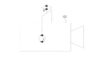
図1は、本発明の第1の実施形態による、機構の一部分の概略斜視図である。機構は、ボール102及びプレート104を備え、機構の使用の間に、ボールが、トラック106にそって移動し、カメラの検出された動きを埋め合わせる。機構それ自身は、画像センサ又はレンズ要素のいずれかと関連付けられ、これらのうちのいずれかをシフトさせることによって、画像センサ上の画像の位置に影響を与えることが可能である。理論として、機構は、光学経路内に配置された鏡が存在するならば鏡などの、光学経路に影響を与えることができる光学システム内の任意の構成要素と関連付けられることができるが、実際には、画像センサ又はレンズアセンブリのいずれかが使用される。
FIG. 1 is a schematic perspective view of a portion of a mechanism according to a first embodiment of the present invention. The mechanism comprises a
ボール/プレート機構の詳細、その基本的な制御又はそのサスペンションは、先行技術で開示されており、本開示の主要な課題ではない。要約すると、何らかの種類のチルトセンサ、例えば、加速度計若しくはジャイロスコープの構成、又はその2つの組み合わせが、カメラの動きを検出するために使用され得る。ズームレベル及び焦点距離に関するレンズパラメータなどの、撮像システムの現在の設定を使用して、プロセッサが、(センサ上の)画像平面内の画像の動きにおける結果としての効果を決定し、レンズアセンブリ又は画像センサ(又はビーム経路に影響を与えることができる任意の他の構成要素)を移動させることによって、対抗する動きが引き起こされ得る。 The details of the ball/plate mechanism, its basic control or its suspension have been disclosed in the prior art and are not the main subject of this disclosure. In summary, any kind of tilt sensor, for example an accelerometer or gyroscope configuration, or a combination of the two may be used to detect camera movement. Using the current settings of the imaging system, such as the lens parameters for zoom level and focal length, the processor determines the resulting effect on the motion of the image in the image plane (on the sensor) and determines the lens assembly or image. By moving the sensor (or any other component that can affect the beam path), counter-movement can be induced.
対抗する動きを実際に引き起こすアクチュエータは、例えば、電磁気力又は圧電構成(piezo arrangement)に基づき得る。使用され得る1つの具体的なタイプのアクチュエータは、いわゆるボイスコイル型アクチュエータであり得るが、他のタイプのアクチュエータが同様に使用されてもよい。 The actuator that actually causes the counter-movement may be based on, for example, an electromagnetic force or a piezo arrangement. One particular type of actuator that may be used may be a so-called voice coil type actuator, although other types of actuators may be used as well.
レンズ又はセンサを移動させるための構成は、1以上のボール/プレート機構を備え得る。実際の実施例において、完全な構成は、安定的な構成を提供するために3つ以上の支持ポイントを有するようである。全ての支持ポイントに、本発明の機構が提供される必要はない。 The arrangement for moving the lens or sensor may comprise one or more ball/plate mechanisms. In a practical example, the complete configuration is likely to have more than two support points to provide a stable configuration. Not all support points need to be provided with the mechanism of the present invention.
図2は、本発明が適用されない状況を示している概略平面図である。(図示せぬ)ボールは、画像を安定化させるために、プレート104に対して、実線によって示されている経路106に沿って動く。経路106は、実際の状況に基づいておらず、それは単に中心ポイントの周りでカメラが自由に動くということに基づいている。カメラが完全に又は部分的に、例えば、固定具又は三脚によって支持されている状況では、パターンが完全に異なり得る。1つの効果は、カメラが別の方向よりも1つの方向において動く傾向があるということであり得る。にもかかわらず、単純化された実施例から、プレート104の中心において過剰な摩耗が存在し、結局、機構の低い性能及び最終的には不具合をもたらすということが明らかである。ただ1つのプレートが、図2(又はその事象に対する任意の図面)で示されているが、通常の設置では、ボールのいずれかの側上に対向する関係で配置される2つのプレートが存在し、一方のプレートは移動されるべきアイテム上に配置され、他方のプレートはベース上に配置される。プレートは孤立した構造体を形成し得ず、それは単に別の構造体の平坦な部分であり得る。実際、ボールは、別のやり方、例えば、ソケット内、構造体のうちの1つ内でぶら下げられ、そのような場合には、ただ1つのプレート又は平坦な部分だけが必要とされ得ることも、明らかにされるべきである。各使用の後でプレート又は複数のプレートが望ましい開始ポイントに戻ることを保証するために、ホールセンサ(hall sensor)構成又は別の機構が使用され得る。
FIG. 2 is a schematic plan view showing a situation to which the present invention is not applied. The ball (not shown) moves relative to the
本発明の第1の例示的な実施形態によれば、移動の第2の経路が適用され得る。図3において、移動の第2の経路が、プレート104上の点線108で示されている。安定化する動きの効果が、図3の図面では考慮されていない。今度は、図3の実施形態において、プレートの表面上でボールを遅く動かすように、機構が構成される。「遅く」という用語は、定量的な基準ではないが、ただ1つの単一の速度が可能であるタイプではない状況が存在し、それは更に議論される。先ず、第2の移動の効果を記述する。図2及び図3の図面を比較する(及び可能性としては組み合わせる)ことによって、効果がしっかりと理解される。図3の第2の移動を使用することによって、図2で示された動きの中心がプレート上で連続的に周回移動し、このことは、プレートの摩耗を低減させ、又は少なくともプレート104のより大きな表面領域上に摩耗を分散させ、それによって、その寿命を効果的に増加させる。ボール102の摩耗は、一般的な基準として、それ程影響を受けないが、より頑丈な材料からボールを製造することによって、全体の機構の組み合わされた寿命は延長され得る。第2の移動は、画像平面内の画像の位置にも影響し、このことは、図7及び図8を参照して議論され、このことは、部分的に「遅く」の定義又はその欠落に関連するので、それも同様にそこで議論される。点線が、安定化の動きが適用されなければボールが有し得る位置、もしそう呼ぶならば「安定化中間点」を表すことも注意されるべきである。安定化の動きが連続的に適用され得る実際の場合には、ボールの実際の経路が点線に全く従わない。しかしながら、その経路は点線と何回か交差するだろう。
According to the first exemplary embodiment of the present invention, a second path of travel may be applied. In FIG. 3, the second path of travel is indicated by the dotted
図3の実施形態において第2の移動が遅く、オプションとして連続的であるならば、図4で示される実施形態の動きは間欠的性質を有する。この実施形態では、ボールがしばらくの間1つの位置に(第2の移動に関して)静止したままであり、その後、ボールは新しい位置に移動し、しばらくの間静止したままであり、それが繰り返される。このことは、図4の接続されたドット(dot)で示され、ドットは、ボールが静止したままである(すなわち、引き起こされる第2の移動が存在しない)位置に対応する。これらの位置の各々では、ボールが、図2で示されたように動き回り、画像安定化に影響を与え、それによって摩耗の分散が達成されてもよい。 If the second movement is slow and optionally continuous in the embodiment of FIG. 3, the movement of the embodiment shown in FIG. 4 has an intermittent nature. In this embodiment, the ball remains stationary in one position (with respect to the second movement) for some time, then moves to a new position, remains stationary for some time, and so on. .. This is indicated by the connected dots in FIG. 4, which correspond to positions where the ball remains stationary (ie there is no second movement to be caused). At each of these positions, the ball may move around as shown in FIG. 2, affecting image stabilization and thereby achieving wear distribution.
また更なる実施形態では、第2の移動が、連続的な動き及び間欠的な動きの組み合わせであり、時間を経て変動する速度プロファイルを効果的に表示し得る。本明細書で議論される本発明は、これらに限定されるべきではなく、少なくともその最も広い範囲において限定的であってはならない。 In yet a further embodiment, the second movement is a combination of continuous movement and intermittent movement, which can effectively display a velocity profile that varies over time. The invention discussed herein should not be limited thereto, nor at least in its broadest scope.
図5によって示される実施形態では、第2の移動を制御するために統計学が使用されている。等高線は、時間にわたるボールの動きによるヒートマップを示すことを意図している。ヒートマップは、摩耗に対して重要なボールの実際の通時的な位置なので、第2の移動を画像安定化の動きから分離する必要がない。図5の実施例を見ると、ボールが、主として右上の象限及び左下の隅に配置されていたことが明らかである。この入力は、第2の移動を制御するために使用され、それによって、ボールが、摩耗を幾らか平等にするために右下の隅又は左上の隅に向けられる。ヒートマップを入力として使用することは、多くの異なるレベルの複雑さの上で実行され、例えば、ヒートマップ(又は対応する統計的な基準)が、入力として連続的に使用され、又は、それが、望ましい第2の経路が次のイベントまでの時間に対して計算される、時間的に間隔が空けられた孤立したイベントで使用され得る。本実施例では、ヒートマップが等高線マップの形態として与えられた。なぜならば、これは例示的であり且つしっかりと理解することが可能な実施例だからである。実際に、ヒートマップは、様々な統計的な基準によって表され、特許請求の範囲で規定される本発明は、この点において限定的であってはならない。 In the embodiment illustrated by FIG. 5, statistics are used to control the second movement. The contour lines are intended to show a heat map of the movement of the ball over time. Since the heat map is the actual diachronic position of the ball that is important to wear, it is not necessary to separate the second movement from the image stabilization movement. Looking at the example of FIG. 5, it is clear that the ball was primarily located in the upper right quadrant and the lower left corner. This input is used to control the second movement, which directs the ball to the lower right corner or the upper left corner to provide some even wear. Using heatmaps as inputs is performed on many different levels of complexity, for example, heatmaps (or corresponding statistical criteria) are used continuously as inputs, or , A desired second path is calculated for the time to the next event, and can be used in time-spaced isolated events. In this embodiment, the heat map is given as a contour map form. This is because this is an example and an example that can be well understood. Indeed, heat maps are represented by various statistical criteria, and the invention defined in the claims should not be limiting in this respect.
図6は、更に別の制御機構を含む更なる実施形態を示している。再び、プレート104が示され、本実施形態では、プレートの表面が、3つの機能的な同心的区域、すなわち、中心区域112、中間区域114、及び外側区域116へ分割されている。実際の状況では、プレート104の表面領域が、明らかに制限され、ボール102にとって移動可能な範囲を制限する。別の所与のパラメータは、カメラが更に動くときに、すなわち、動きの大きさが増加するときに、ボールに対して使用される動きの範囲が、同様に増加するということである。このことは、第2の移動の制御に対する有用な入力として使用され得る。要するに、カメラに対する動きの増加した大きさが、加速度計又はジャイロスコープ(又は他の適切なセンサ)によって検出された際に、第2の移動は、ボール102をプレート104の中央へ向けて動かすように、制御される。図6の実施形態では、特定の大きさを超えてボール102が中心区域112へ及び中心区域112内へ移動するように制御され、特定の大きさ未満でボール102が外側区域116へ及び外側区域116内へ移動するように制御され、且つこれらの大きさの間でボール102が中間区域114へ及び中間区域114内へ移動するように制御され得る。「へ及び内へ」という語句は、ボールがこれらの区域内へ排他的に移動するように制御されることを意味せず、カメラを安定化するために引き起こされた動きが、未だ、ボールを意図された領域の外側へ移動させる原因となり得る。
FIG. 6 illustrates a further embodiment that includes yet another control mechanism. Again, the
本実施形態における3つの区域の使用は、4つ、5つ、6つなどのより多い区域、2つなどのより少ない区域、又は区域が全く存在し得ない場合よりも、説明が簡単であるという理由のみに基づいて採用されている。後者の実施例は、第2の移動に対する作動半径が、連続的で、逆向きな、カメラの動きの大きさの関数だということであり得る。開示される実施形態では、カメラの動きの大きさが入力として使用されるが、実際の関数は、より短い期間又は延長された期間にわたるカメラの動きの周波数、統計などの、それ以外のパラメータに依存し得る。 The use of three zones in this embodiment is easier to describe than if there could be more zones such as four, five, six, less zones such as two, or no zones at all. It has been adopted based on only that reason. An example of the latter may be that the working radius for the second movement is a function of the magnitude of the continuous, reverse, camera movement. In the disclosed embodiment, the magnitude of the camera motion is used as an input, but the actual function is for other parameters such as the frequency of the camera motion over a shorter or extended period, statistics, etc. Can depend.
図5及び図6に関して開示された任意の実施形態では、図3又は図4に関して開示された移動パターンが適用され得る。したがって、それは連続的な移動、間欠的な移動、変動する速度の移動、又はそれらの組み合わせであり得る。 In any of the embodiments disclosed with respect to FIGS. 5 and 6, the movement pattern disclosed with respect to FIG. 3 or 4 may be applied. As such, it can be continuous movement, intermittent movement, varying speed movement, or a combination thereof.
以下のセクションでは、第2の移動の効果がいかにしてキャンセルされ得るかの2、3の実施例が、説明される。 In the following section, a few examples of how the effect of the second movement can be canceled will be described.
図7では、情景の画像が例示されている。画像センサ上に撮像されたものは、外側の長方形118によって画定され、ディスプレイ上で示され又は少なくともビデオストリームで流されるものは、内側の点線の長方形120によって画定される。本実施例では、画像センサが寸法過大であると言われ得るが、アナログデジタルズーム(analogue to digital zoom)を使用することによって、同じ効果が取得され得る。図8の図面では、第2の移動が、画像センサ上に撮像された画像の位置をシフトさせたが、センサが寸法過大である(又はデジタルズームが使用される)という事実のために、前と同じ領域がユーザに示され得る。図7と図8との間の位置におけるシフトは、実際、何百のフレームほど離れており、それによって、第2の移動によってもたらされた段階的な画像シフトは、人間の目又は、例えば、動きを検出するために開発された検出アルゴリズムのいずれによっても検出されない。
In FIG. 7, an image of a scene is illustrated. What is imaged on the image sensor is defined by the
第2の移動に対する動きの正確な速度は、好ましくは、それが、隣接する画像フレームの間の撮像された視野内の画素のごく一部のシフトをもたらすべきである。速度がフレーム毎に画素の1/100と一致するぐらい低い場合でさえ、30〜60フレーム/秒(fps)の一般的なフレーム速度は、第2の移動が、摩耗低減の観点から注目に値するということをもたらす。このことは、更に例示され得る。速度がフレーム毎に画素の1/100であること、及び1080pのセンサが使用されることを考慮する。最大でセンサの20%、すなわち、約200画素を広げる第2の移動を引き起こし得ると、想定することができる。そのとき、その距離だけ移動することは、20000フレームほど必要とし、それは、30fpsにおける約10分に相当する。そのとき、図3で例示されたタイプのパターン又は経路は、開始から終了まで(又は開始から再開まで)約30分必要とし得る。 The exact rate of motion for the second movement should preferably result in a shift of a small fraction of the pixels in the imaged field of view between adjacent image frames. Typical frame rates of 30-60 frames per second (fps) are notable for a second movement in terms of wear reduction, even when the rate is low enough to match 1/100th of a pixel per frame. Bring that. This can be further illustrated. Consider that the velocity is 1/100th of a pixel per frame and that a 1080p sensor is used. It can be assumed that it can cause a second movement that spreads out at most 20% of the sensor, ie about 200 pixels. Moving that distance then requires about 20000 frames, which corresponds to about 10 minutes at 30 fps. Then, a pattern or path of the type illustrated in FIG. 3 may require about 30 minutes from start to finish (or start to restart).
第2の移動に対する示唆された速度は、実際の観点から推測され、その観点からフレーム毎に画素の1/10が、同様に可能であり、且つより遅い速度も同様である。動きを遅くする場合に、自明な下限は存在しない。結局、動きの速度を上げるときに、それは、画像内に不自然なもの(artifact)をもたらし得る。これらの不自然なものは、例えば、解析(deconvolution)によって修正され得るが、計算上の観点から同様な修正が必要となり、そのことは、それらを、ライブ映像が存在する用途において、より不適切なものとする。 The suggested speed for the second move is inferred from a practical point of view, from which point 1/10 of a pixel per frame is likewise possible, as well as a slower rate. There is no trivial lower bound when slowing motion. After all, as it speeds up the motion, it can lead to artifacts in the image. These artifacts can be modified, for example, by deconvolution, but require a similar modification from a computational point of view, which makes them less suitable for applications where live video is present. It should be
多くの実施形態では、第2の移動が、画像センサ上の画像の周りを移動し、したがって、ユーザに対して表示されるべきセンサの領域の選択が実行されなければならない。ユーザに示される領域の選択は、制御された第2の移動、レンズシステムの現在の設定などから推測され、すなわち、それは予測可能であり、様々な利用可能な入力データから計算され得る。 In many embodiments, the second movement moves around the image on the image sensor, so selection of the area of the sensor to be displayed to the user has to be performed. The selection of the area shown to the user is inferred from the controlled second movement, the current setting of the lens system, etc., ie it is predictable and can be calculated from various available input data.
上述の段落の予測手法を使用することの代替例又は追加例は、デジタル画像安定化、例えば、隣接するフレーム内の特徴の特定及び局所化に基づくデジタル画像安定化を使用することであり得る。特に、既存のデジタル画像安定化は、様々なセンサからの入力によって支持され、結局、技術の組み合わせが、望ましい最終結果に到達するために使用され得る。 An alternative or addition to using the prediction technique in the above paragraph may be to use digital image stabilization, for example digital image stabilization based on the identification and localization of features in adjacent frames. In particular, existing digital image stabilization is supported by inputs from various sensors, and eventually a combination of techniques can be used to reach the desired end result.
本発明の追加された利点は、その実施形態の全てにおいて、あらゆる複雑な技術を必要とせず、少なくとも、技術の明らかな領域内で利用可能な技術に照らして考慮するならば、必要としないということである。基本的に、今日の光学画像安定化に対して使用される任意の駆動ユニットが使用され、ボールの位置をモニタリングするための技術が、同様に、存在する。本発明の目的に対して、興味の対象はボールの位置であるが、この情報は、ボールが相互作用するプレート又は複数のプレートの位置又は動きをモニタリングすることによって推測し得る。 The added advantage of the present invention is that it does not require any complex technology in all of its embodiments, or at least, given the technology available within the obvious areas of technology. That is. Essentially any drive unit used for optical image stabilization today is used, and techniques for monitoring the position of the ball exist as well. For purposes of the present invention, it is the position of the ball that is of interest, but this information can be inferred by monitoring the position or movement of the plate or plates with which the ball interacts.
更に、光学画像安定化は、全てのタイプの振れ又は振動の効果を除去することができ得ない。一般的な実施例では、光学画像安定化が、(1つの端部又はそれより多くの端部においてオープンであり、幾つかの間隔区域を含み得る)第1の周波数間隔内の動きの安定化をもたらすように使用され、一方で、デジタル画像安定化が、(1つの端部又はそれより多くの端部においてオープンであり、幾つかの間隔区域を含み得る)第2の周波数間隔内の動きの安定化をもたらすように使用され得ることが指摘されている。第1及び第2の周波数間隔は、部分的に重なり得る。デジタル画像安定化は、ジャイロ又は安定化機構が反応するのに遅過ぎる、より高い周波数での修正をもたらし、一方、光学画像安定化は、より低い周波数での修正をもたらし、又はその逆であってもよい。 Moreover, optical image stabilization cannot eliminate all types of shake or vibration effects. In a general embodiment, optical image stabilization is stabilization of motion within a first frequency interval (open at one or more edges and may include several intervals). Digital image stabilization, while the digital image stabilization is open at one or more edges and may include several spacing zones It has been pointed out that it can be used to bring about stabilization of The first and second frequency intervals may partially overlap. Digital image stabilization results in corrections at higher frequencies that are too slow for the gyro or stabilization mechanism to respond, while optical image stabilization results in corrections at lower frequencies, or vice versa. May be.
第2の移動が部分的にカメラの検出された動きによって制御された、図6を参照して説明された実施形態に戻ると、第2の移動によってもたらされた視覚的効果の除去に対する最近の説明され提案された解決法が、カメラの望ましくない動きの状況において使用され得る。一実施形態では、したがって、プロセッサが、カメラの望ましくない動きが検出されたならば、光学的にズームアウト、したがって、(図7及び図8の領域118に対応する)画像センサ上で撮像された視野を拡大するように構成される。このことは、カメラが、ユーザに示される領域に影響を与え始める前に、移動することができる量を効果的に増加させる。ズームアウトの結果として、プロセッサは、ズームアウト手順の効果を隠す目的で、ユーザに対して示される視野を再スケーリングもしなければならない。この手順は、機構又は実際には機構を備えたカメラの安定化能力範囲を増加させる。
Returning to the embodiment described with reference to FIG. 6, in which the second movement was partly controlled by the detected movement of the camera, a recent approach to the elimination of the visual effect brought about by the second movement Described and proposed solution can be used in situations of unwanted camera movement. In one embodiment, therefore, the processor optically zooms out and thus images on the image sensor (corresponding to
光学的なズームアウト及びズームインの使用は、118と120との間のサイズにおける差異のために、捨てられる画素の量を最小化するためにも使用され得る。第2の移動経路がプレートの中央部分にあるときに、光学ズームは、等しいサイズの118及び120を作るように設定され得る。第2の移動がプレートの中心から更に離れて動くと、120の全部が118に含まれるようにするために、カメラは、光学的によりズームアウトしなければならない。その後、120の画像は、連続的な画像ストリームと適合するように、一般的なサイズへスケーリングされ得る。
The use of optical zoom out and zoom in can also be used to minimize the amount of pixels discarded due to the difference in size between 118 and 120. When the second path of travel is in the central portion of the plate, the optical zoom can be set to make
同じ又は関連する実施形態では、(その安定化の動きにおける)ボールの変位に基づいて、ズームレベルが動的に変動し、必要とされる埋め合わせの量が最小化され得る。クロッピングの場合、ボールがプレートの中心に近づくときに、このことは、より高い解像度を意味する。 In the same or related embodiments, the zoom level may be dynamically varied based on the displacement of the ball (in its stabilizing movement) to minimize the amount of make-up required. In the case of cropping, this means higher resolution when the ball approaches the center of the plate.
図9は、第2の移動の効果の除去がハードウェアを使用して行われる、一実施形態を例示している。図9は、パン及びチルトできるように概略的にぶら下げられたカメラ122を示している。プロセッサは、第2の移動の効果が、パンP及びチルトT方向における対抗する動きによって除去されるように、パン機構及びチルト機構を制御するために使用され得る。考慮された効果は、明らかに、摩耗低減の効果よりも、画像チップ上の画像の位置決めについての効果である。
FIG. 9 illustrates an embodiment in which the removal of the effect of the second move is performed using hardware. FIG. 9 shows a
図7、図8、及び図9の実施形態は、適切に考慮されるとすれば、自由に組み合され得る。この一実施例として、パン及びチルトモータの使用が、任意の残留効果を低減させるために、デジタル画像安定化によって支持され得る。
The embodiments of FIGS. 7, 8 and 9 can be freely combined, if considered properly. As one example of this, the use of pan and tilt motors can be favored by digital image stabilization to reduce any residual effects.
Claims (14)
前記カメラの動きを感知することができる動作センサと、
前記カメラの光学経路内の、レンズ要素又は画像センサである要素と、
前記要素が前記光学経路と垂直な平面内で移動することを可能にするベアリングとして働くボール(102)及びプレート(104)と、
前記平面内で前記要素を移動させることができる、アクチュエータ機構と、
前記動作センサによって検出された際に前記カメラの動きに応じて前記要素を移動させるように前記アクチュエータを制御し、それによって、前記カメラ(122)からの画像を安定化させるように構成された、プロセッサとを備え、
前記プロセッサが更に、前記アクチュエータを制御するように構成され、前記アクチュエータが、前記ボールによって生成される前記プレート上の摩耗を分散させるために、安定化中間点をシフトするように第2の移動経路(108)に沿って前記要素を移動させ、
前記プロセッサが更に、前記画像をシフトさせるための他の手段によって、前記第2の移動経路により生成された画像シフトを埋め合わせることができ、
フレーム毎に前記画像センサの画素のごく一部よりも小さい前記カメラの視野内のシフトをもたらすように、前記第2の移動経路に沿った移動の速度が制限されることを特徴とする、画像安定化機構。 An image stabilization mechanism for the camera (122) , comprising:
A motion sensor capable of sensing the movement of the camera,
An element that is a lens element or an image sensor in the optical path of the camera,
A ball (102) and plate (104) that act as bearings to allow the element to move in a plane perpendicular to the optical path;
An actuator mechanism capable of moving the element in the plane;
Configured to control the actuator to move the element in response to movement of the camera when detected by the motion sensor, thereby stabilizing the image from the camera (122) ; With a processor,
The processor is further configured to control the actuator , the second path of travel for the actuator to shift a stabilization midpoint to disperse wear on the plate produced by the ball. Move the element along (108) ,
The processor may further compensate for the image shift produced by the second path of travel by other means for shifting the image ,
To provide a shift in the small part smaller than the cameras field of view of the pixels of the image sensor for each frame, the speed of movement and limited said Rukoto along the second movement path, the image Stabilization mechanism.
動作センサによって前記カメラの動きを検出することと、
前記動きの情報を前記カメラのプロセッサに転送することと、
前記プロセッサを使用して、前記カメラの前記動きに対抗するために光学経路内の前記要素を移動させるようにアクチュエータを制御することと、
前記ボールによって生成される前記プレート上の摩耗を分散させるために、前記プロセッサを使用して、第2の移動経路に沿って前記光学経路内の前記要素を移動させるように前記アクチュエータを制御することとを含み、
前記要素が、ボール(102)及びプレート(104)のサスペンションによってぶら下げられる、方法。 A method for controlling a stabilization mechanism for a camera comprising an image stabilization mechanism according to any one of claims 1 to 8 , comprising:
Detecting movement of the camera by a motion sensor;
Transferring the motion information to a processor of the camera;
And that by using the processor to control the actuator to move the element in the optical path in order to counteract the motion of the camera,
Controlling the actuator to move the element in the optical path along a second path of travel using the processor to disperse wear on the plate produced by the ball. Including and
The method wherein the elements are suspended by a suspension of balls (102) and plates (104) .
Applications Claiming Priority (2)
| Application Number | Priority Date | Filing Date | Title |
|---|---|---|---|
| EP15170472.3 | 2015-06-03 | ||
| EP15170472.3A EP3101890B1 (en) | 2015-06-03 | 2015-06-03 | A mechanism and a method for optical image stabilization |
Publications (3)
| Publication Number | Publication Date |
|---|---|
| JP2017032977A JP2017032977A (en) | 2017-02-09 |
| JP2017032977A5 JP2017032977A5 (en) | 2019-06-27 |
| JP6710102B2 true JP6710102B2 (en) | 2020-06-17 |
Family
ID=53432985
Family Applications (1)
| Application Number | Title | Priority Date | Filing Date |
|---|---|---|---|
| JP2016102990A Active JP6710102B2 (en) | 2015-06-03 | 2016-05-24 | Mechanism and method for optical image stabilization |
Country Status (6)
| Country | Link |
|---|---|
| US (1) | US10091425B2 (en) |
| EP (1) | EP3101890B1 (en) |
| JP (1) | JP6710102B2 (en) |
| KR (1) | KR102173097B1 (en) |
| CN (1) | CN106254758B (en) |
| TW (1) | TWI735445B (en) |
Families Citing this family (1)
| Publication number | Priority date | Publication date | Assignee | Title |
|---|---|---|---|---|
| WO2019065822A1 (en) | 2017-09-28 | 2019-04-04 | 富士フイルム株式会社 | Imaging device, and operation method and operation program therefor |
Family Cites Families (33)
| Publication number | Priority date | Publication date | Assignee | Title |
|---|---|---|---|---|
| DE19942900B4 (en) * | 1998-09-08 | 2004-01-22 | Ricoh Company, Ltd. | Device for correcting image errors caused by camera shake |
| CN1802583A (en) * | 2003-06-09 | 2006-07-12 | 奥林巴斯株式会社 | Variable mirror |
| DE102004045430A1 (en) * | 2004-09-18 | 2006-05-18 | Deutsche Telekom Ag | Device for image stabilization |
| US20070102622A1 (en) * | 2005-07-01 | 2007-05-10 | Olsen Richard I | Apparatus for multiple camera devices and method of operating same |
| KR20080081003A (en) * | 2005-11-30 | 2008-09-05 | 노키아 코포레이션 | Method and system for image stabilization |
| JP2007163594A (en) * | 2005-12-09 | 2007-06-28 | Canon Inc | Optical equipment and imaging system |
| JP2008233526A (en) * | 2007-03-20 | 2008-10-02 | Tamron Co Ltd | Actuator for preventing image shake and camera equipped therewith |
| US7978222B2 (en) * | 2008-03-01 | 2011-07-12 | Avago Technologies Ecbu Ip (Singapore) Pte. Ltd. | Systems and methods for image stabilization |
| JP4462372B2 (en) * | 2008-06-13 | 2010-05-12 | ソニー株式会社 | Blur correction unit and imaging apparatus |
| WO2010010712A1 (en) * | 2008-07-24 | 2010-01-28 | パナソニック株式会社 | Camera driver |
| JP5535079B2 (en) * | 2008-10-14 | 2014-07-02 | 日本電産サンキョー株式会社 | Optical device for photography |
| US8442392B2 (en) * | 2009-12-22 | 2013-05-14 | Nokia Corporation | Method and apparatus for operating the automatic focus or the optical imaging stabilizing system |
| JP5593118B2 (en) * | 2010-04-30 | 2014-09-17 | 日本電産サンキョー株式会社 | Optical unit with shake correction function |
| JP5622443B2 (en) * | 2010-06-08 | 2014-11-12 | 日本電産サンキョー株式会社 | Optical unit with shake correction function |
| WO2011155318A1 (en) * | 2010-06-08 | 2011-12-15 | 日本電産サンキョー株式会社 | Blur correction device, image capturing optical apparatus, and lens drive apparatus |
| JP5580684B2 (en) | 2010-07-29 | 2014-08-27 | オリンパスイメージング株式会社 | Image stabilization apparatus and camera |
| TWI409577B (en) * | 2010-08-20 | 2013-09-21 | Primax Electronics Ltd | Optical image system |
| US8711235B2 (en) * | 2011-05-16 | 2014-04-29 | Rpx Corporation | Image stabilization |
| TWI529471B (en) * | 2011-05-20 | 2016-04-11 | 鴻海精密工業股份有限公司 | Image stabilizing module and image capturing device |
| JP5848052B2 (en) * | 2011-07-21 | 2016-01-27 | 日本電産サンキョー株式会社 | Optical unit with shake correction function |
| US8855476B2 (en) * | 2011-09-28 | 2014-10-07 | DigitalOptics Corporation MEMS | MEMS-based optical image stabilization |
| EP2611151B1 (en) * | 2011-12-29 | 2014-01-22 | Axis AB | Method and mobile unit for facilitating installation of a surveillance camera |
| KR101975893B1 (en) * | 2012-03-21 | 2019-09-10 | 엘지이노텍 주식회사 | Camera Module |
| US9134503B2 (en) * | 2012-07-06 | 2015-09-15 | Apple Inc. | VCM OIS actuator module |
| US9398264B2 (en) * | 2012-10-19 | 2016-07-19 | Qualcomm Incorporated | Multi-camera system using folded optics |
| JP2015036716A (en) * | 2013-08-12 | 2015-02-23 | ソニー株式会社 | Image blur correction device and imaging device |
| CN104519239A (en) * | 2013-09-29 | 2015-04-15 | 诺基亚公司 | Method and device for video anti-shaking |
| CN203745777U (en) * | 2014-01-10 | 2014-07-30 | 瑞声声学科技(深圳)有限公司 | Array type lens device |
| KR101433846B1 (en) * | 2014-03-14 | 2014-08-26 | 주식회사 퓨런티어 | Test apparatus for optical image stabilization module and test method for optical image stabilization module |
| US9541740B2 (en) * | 2014-06-20 | 2017-01-10 | Qualcomm Incorporated | Folded optic array camera using refractive prisms |
| CN204086644U (en) * | 2014-08-25 | 2015-01-07 | 瑞声精密制造科技(常州)有限公司 | Lens driving apparatus |
| US9832381B2 (en) * | 2014-10-31 | 2017-11-28 | Qualcomm Incorporated | Optical image stabilization for thin cameras |
| CN204287688U (en) * | 2014-12-19 | 2015-04-22 | 深圳市世尊科技有限公司 | A kind of voice coil motor being realized optical anti-vibration by pure translational movement |
-
2015
- 2015-06-03 EP EP15170472.3A patent/EP3101890B1/en active Active
-
2016
- 2016-05-24 JP JP2016102990A patent/JP6710102B2/en active Active
- 2016-05-27 CN CN201610363979.8A patent/CN106254758B/en active Active
- 2016-05-27 KR KR1020160065767A patent/KR102173097B1/en active IP Right Grant
- 2016-06-02 US US15/171,496 patent/US10091425B2/en active Active
- 2016-06-03 TW TW105117662A patent/TWI735445B/en active
Also Published As
| Publication number | Publication date |
|---|---|
| TW201703507A (en) | 2017-01-16 |
| CN106254758A (en) | 2016-12-21 |
| KR102173097B1 (en) | 2020-11-02 |
| JP2017032977A (en) | 2017-02-09 |
| US10091425B2 (en) | 2018-10-02 |
| EP3101890B1 (en) | 2017-11-22 |
| CN106254758B (en) | 2020-03-13 |
| US20160360113A1 (en) | 2016-12-08 |
| KR20160142773A (en) | 2016-12-13 |
| EP3101890A1 (en) | 2016-12-07 |
| TWI735445B (en) | 2021-08-11 |
Similar Documents
| Publication | Publication Date | Title |
|---|---|---|
| JP6574645B2 (en) | Control device for controlling imaging apparatus, control method for imaging apparatus, and program | |
| KR20180051643A (en) | SYSTEMS AND METHODS FOR PERFORMING AUTOMATIC ZOOM | |
| JP5235910B2 (en) | Camera head system | |
| CN108141540B (en) | Omnidirectional camera with motion detection | |
| JP2008312242A (en) | Imaging device | |
| JP2011091546A5 (en) | Intruder monitoring system and intruder monitoring method | |
| TW202026704A (en) | Optical image stabilization techniques | |
| JP2011142419A5 (en) | ||
| TW202034675A (en) | Optical image stabilization techniques | |
| JP6710102B2 (en) | Mechanism and method for optical image stabilization | |
| US20160057349A1 (en) | Image processing apparatus and control method for same | |
| JP2008046181A (en) | Focus controller, focus control method, imaging apparatus and program | |
| US10194090B2 (en) | View angle control apparatus and view angle control method | |
| US11843861B2 (en) | Apparatus, method, and storage media | |
| JPH10294890A (en) | Automatic/manual photographic camera system | |
| US8786677B2 (en) | Imaging device | |
| JP2010286679A (en) | Imaging apparatus | |
| JP6912923B2 (en) | Image pickup device, drive mechanism of image pickup device, and control method thereof | |
| JP2019219529A (en) | Control device, imaging device, control method, program, and storage medium | |
| JP6597080B2 (en) | Imaging device | |
| JP2013197822A (en) | Imaging device, method for controlling the same, and control program | |
| JP2017032977A5 (en) | ||
| JP2015103918A (en) | Imaging apparatus and imaging apparatus control method | |
| US20180376058A1 (en) | Display processing apparatus, display processing method, and computer-readable medium for executing display processing method | |
| Gao et al. | Zoom control of wide area tracking system |
Legal Events
| Date | Code | Title | Description |
|---|---|---|---|
| A521 | Request for written amendment filed |
Free format text: JAPANESE INTERMEDIATE CODE: A523 Effective date: 20190524 |
|
| A621 | Written request for application examination |
Free format text: JAPANESE INTERMEDIATE CODE: A621 Effective date: 20190524 |
|
| TRDD | Decision of grant or rejection written | ||
| A01 | Written decision to grant a patent or to grant a registration (utility model) |
Free format text: JAPANESE INTERMEDIATE CODE: A01 Effective date: 20200428 |
|
| A61 | First payment of annual fees (during grant procedure) |
Free format text: JAPANESE INTERMEDIATE CODE: A61 Effective date: 20200526 |
|
| R150 | Certificate of patent or registration of utility model |
Ref document number: 6710102 Country of ref document: JP Free format text: JAPANESE INTERMEDIATE CODE: R150 |
|
| R250 | Receipt of annual fees |
Free format text: JAPANESE INTERMEDIATE CODE: R250 |
|
| R250 | Receipt of annual fees |
Free format text: JAPANESE INTERMEDIATE CODE: R250 |