JP6709214B2 - Arm support system - Google Patents
Arm support system Download PDFInfo
- Publication number
- JP6709214B2 JP6709214B2 JP2017521574A JP2017521574A JP6709214B2 JP 6709214 B2 JP6709214 B2 JP 6709214B2 JP 2017521574 A JP2017521574 A JP 2017521574A JP 2017521574 A JP2017521574 A JP 2017521574A JP 6709214 B2 JP6709214 B2 JP 6709214B2
- Authority
- JP
- Japan
- Prior art keywords
- arm
- arm support
- support segment
- axis
- user
- Prior art date
- Legal status (The legal status is an assumption and is not a legal conclusion. Google has not performed a legal analysis and makes no representation as to the accuracy of the status listed.)
- Active
Links
Images


Classifications
-
- A—HUMAN NECESSITIES
- A61—MEDICAL OR VETERINARY SCIENCE; HYGIENE
- A61F—FILTERS IMPLANTABLE INTO BLOOD VESSELS; PROSTHESES; DEVICES PROVIDING PATENCY TO, OR PREVENTING COLLAPSING OF, TUBULAR STRUCTURES OF THE BODY, e.g. STENTS; ORTHOPAEDIC, NURSING OR CONTRACEPTIVE DEVICES; FOMENTATION; TREATMENT OR PROTECTION OF EYES OR EARS; BANDAGES, DRESSINGS OR ABSORBENT PADS; FIRST-AID KITS
- A61F5/00—Orthopaedic methods or devices for non-surgical treatment of bones or joints; Nursing devices; Anti-rape devices
- A61F5/01—Orthopaedic devices, e.g. splints, casts or braces
- A61F5/0102—Orthopaedic devices, e.g. splints, casts or braces specially adapted for correcting deformities of the limbs or for supporting them; Ortheses, e.g. with articulations
- A61F5/013—Orthopaedic devices, e.g. splints, casts or braces specially adapted for correcting deformities of the limbs or for supporting them; Ortheses, e.g. with articulations for the arms, hands or fingers
-
- B—PERFORMING OPERATIONS; TRANSPORTING
- B25—HAND TOOLS; PORTABLE POWER-DRIVEN TOOLS; MANIPULATORS
- B25J—MANIPULATORS; CHAMBERS PROVIDED WITH MANIPULATION DEVICES
- B25J19/00—Accessories fitted to manipulators, e.g. for monitoring, for viewing; Safety devices combined with or specially adapted for use in connection with manipulators
- B25J19/0008—Balancing devices
- B25J19/0016—Balancing devices using springs
-
- B—PERFORMING OPERATIONS; TRANSPORTING
- B25—HAND TOOLS; PORTABLE POWER-DRIVEN TOOLS; MANIPULATORS
- B25J—MANIPULATORS; CHAMBERS PROVIDED WITH MANIPULATION DEVICES
- B25J9/00—Programme-controlled manipulators
- B25J9/0006—Exoskeletons, i.e. resembling a human figure
-
- A—HUMAN NECESSITIES
- A61—MEDICAL OR VETERINARY SCIENCE; HYGIENE
- A61F—FILTERS IMPLANTABLE INTO BLOOD VESSELS; PROSTHESES; DEVICES PROVIDING PATENCY TO, OR PREVENTING COLLAPSING OF, TUBULAR STRUCTURES OF THE BODY, e.g. STENTS; ORTHOPAEDIC, NURSING OR CONTRACEPTIVE DEVICES; FOMENTATION; TREATMENT OR PROTECTION OF EYES OR EARS; BANDAGES, DRESSINGS OR ABSORBENT PADS; FIRST-AID KITS
- A61F5/00—Orthopaedic methods or devices for non-surgical treatment of bones or joints; Nursing devices; Anti-rape devices
- A61F5/01—Orthopaedic devices, e.g. splints, casts or braces
- A61F5/0102—Orthopaedic devices, e.g. splints, casts or braces specially adapted for correcting deformities of the limbs or for supporting them; Ortheses, e.g. with articulations
- A61F2005/0132—Additional features of the articulation
- A61F2005/0134—Additional features of the articulation with two orthogonal pivots
-
- A—HUMAN NECESSITIES
- A61—MEDICAL OR VETERINARY SCIENCE; HYGIENE
- A61F—FILTERS IMPLANTABLE INTO BLOOD VESSELS; PROSTHESES; DEVICES PROVIDING PATENCY TO, OR PREVENTING COLLAPSING OF, TUBULAR STRUCTURES OF THE BODY, e.g. STENTS; ORTHOPAEDIC, NURSING OR CONTRACEPTIVE DEVICES; FOMENTATION; TREATMENT OR PROTECTION OF EYES OR EARS; BANDAGES, DRESSINGS OR ABSORBENT PADS; FIRST-AID KITS
- A61F5/00—Orthopaedic methods or devices for non-surgical treatment of bones or joints; Nursing devices; Anti-rape devices
- A61F5/01—Orthopaedic devices, e.g. splints, casts or braces
- A61F5/0102—Orthopaedic devices, e.g. splints, casts or braces specially adapted for correcting deformities of the limbs or for supporting them; Ortheses, e.g. with articulations
- A61F2005/0132—Additional features of the articulation
- A61F2005/0179—Additional features of the articulation with spring means
-
- A—HUMAN NECESSITIES
- A61—MEDICAL OR VETERINARY SCIENCE; HYGIENE
- A61H—PHYSICAL THERAPY APPARATUS, e.g. DEVICES FOR LOCATING OR STIMULATING REFLEX POINTS IN THE BODY; ARTIFICIAL RESPIRATION; MASSAGE; BATHING DEVICES FOR SPECIAL THERAPEUTIC OR HYGIENIC PURPOSES OR SPECIFIC PARTS OF THE BODY
- A61H1/00—Apparatus for passive exercising; Vibrating apparatus ; Chiropractic devices, e.g. body impacting devices, external devices for briefly extending or aligning unbroken bones
- A61H1/02—Stretching or bending or torsioning apparatus for exercising
- A61H1/0274—Stretching or bending or torsioning apparatus for exercising for the upper limbs
Description
本願は、その開示の全体が参照によって本明細書に明示的に組み入れられる、2014年10月24日出願の同時継続の仮出願番号第62/068,547号の利益を主張する。さらに、本願は、その開示の全体が参照によって本明細書に明示的に組み入れられる、2012年1月18日出願の出願番号第13/353,268号、2012年7月31日出願の出願番号第13/563728号、2013年12月10日出願の出願番号第14/102,466号、並びに、2014年3月24日出願の仮出願番号第61/969,440号及び2014年4月8日出願の出願番号第61/977,060号に関連する。
This application claims the benefit of co-pending
本発明は、ユーザの腕を支持するシステム、装置及び方法に関し、例えば片腕又は両腕を伸ばした状態で長時間にわたってユーザが1以上のタスクを実行することを可能にするために、例えばユーザの片腕又は両腕を支持する一方で実質的に自由運動を可能にする適応腕支持システムに関する。 The present invention relates to systems, devices and methods for supporting a user's arm, for example to allow the user to perform one or more tasks over extended periods of time with one or both arms extended. An adaptive arm support system that supports one or both arms while allowing substantially free movement.
多くのタスクが、人々に、腕を広げた状態で、例えば彼らが少なくとも部分的に自身を支持する必要がある手動工具や他の機器を操作しながら業務を行うことを求める。例は、建設、手術、歯学、絵画、皿洗い及び製造組立を含む。そうした活動に従事する人は、腕を伸ばした状態に維持するために自身の腕にかかる重力に耐えることを必要とする長時間の筋肉運動からくる疲労を経験したことがある。弱者又は障害者は、日常のタスクを実行する疲労を経験したことがある。椅子や作業テーブルの静止したアームレストは、タスクが、例えばコンピュータのキーボードでの比較的に制限された領域内で実行される場合にしか有効ではない。非常に大きな可動域を包含するタスクは、静止したアームレストによって援助されることはない。 Many tasks require people to perform their work with their arms outstretched, for example while manipulating hand tools or other equipment they need to at least partially support themselves. Examples include construction, surgery, dentistry, painting, dishwashing and manufacturing assembly. Those engaged in such activities have experienced fatigue resulting from lengthy muscle exercises that require them to withstand the gravity exerted on their arms to keep them stretched. The vulnerable or handicapped may have experienced fatigue performing routine tasks. Stationary armrests on chairs and worktables are only effective when tasks are performed within a relatively limited area, for example on a computer keyboard. Tasks involving very large excursions are not assisted by stationary armrests.
従って、中くらいの範囲から大きな範囲まで可動域を包含するタスクを実行する及び/若しくは工具又は他の機器を操作する人が経験する疲労を緩和し得るシステムが求められている。 Therefore, there is a need for a system that can alleviate the fatigue experienced by persons performing tasks involving a range of motion from medium to large ranges and/or operating tools or other equipment.
本発明は、ユーザの腕を支持するシステム、装置及び方法に関し、例えば片腕又は両腕を伸ばした状態で長時間にわたってユーザが1以上のタスクを実行することを可能にするために、例えばユーザの片腕又は両腕を支持する一方で実質的に自由運動を可能にする適応腕支持システム又は装置に関する。 The present invention relates to systems, devices and methods for supporting a user's arm, for example to allow the user to perform one or more tasks over extended periods of time with one or both arms extended. An adaptive arm support system or device that supports one or both arms while allowing substantially free movement.
腕支持システムは、腕を伸ばすこと及び腕を上げることを必要とするタスクのパフォーマンスを援助するためにユーザの腕に持ち上げ力を提供するために使用可能である。 The arm support system can be used to provide lifting force to the user's arm to assist in the performance of tasks that require stretching and raising the arm.
ばね荷重の腕支持システムは、単純であり、かつ、外部電源を必要としないが、ばね力が変位とともに増大し、(上げることをほとんど必要としない)腕の最下位置で最もばね力が大きくなるといった望ましくない副作用を有する場合がある。 The spring-loaded arm support system is simple and does not require an external power source, but the spring force increases with displacement, with the highest spring force at the lowest position of the arm (which requires little to raise). May have undesirable side effects such as
例えば、腕を上げる時の力を増加させることによって、また、腕を下げる時の力を減少させることによって、ユーザの腕に対する持ち上げ力を変更することが望まれる。 For example, it is desirable to change the lifting force on the user's arm by increasing the force when raising the arm and by decreasing the force when lowering the arm.
ばねが撓む(及び従ってさらなる正味の持ち上げ力を付加する)際にばねを「不利な状態にする(disadvantaging)」ことによって、例えば、ユーザの腕が下げられてばねが撓ませられる(ばねの力を増大させる)際にシステムへの機械的利益を減少させることによって、解決策が提供される。 By "disadvantaging" the spring as it flexes (and thus adds additional net lifting force), for example, the user's arm is lowered to flex the spring (spring A solution is provided by reducing the mechanical benefit to the system when increasing the force).
ばねを「不利な状態にする」ためのいくつかの機構は、
a)システムに作用する張力要素の角度を変更すること、
b)その周りに張力要素が巻き付けられるプーリの半径を変更すること、
c)2つの上記機構を組み合わせること、
d)作用点を移動させて、システムに作用する張力要素の角度を変更すること、
e)作用点を移動させて、トーションばね機構へのてこの力を変更すること、及び/又は、
f)システムの張力要素の作用点を移動させること、を含んでもよい。
Some mechanisms for "breaking down" a spring are:
a) changing the angle of the tension element acting on the system,
b) changing the radius of the pulley around which the tension element is wound,
c) combining the two above mechanisms,
d) moving the point of action to change the angle of the tension element acting on the system,
e) moving the point of action to change the leverage force on the torsion spring mechanism, and/or
f) moving the point of action of the tension element of the system.
一実施形態によれば、ユーザの腕を支持するシステムが提供され、当該システムは、ユーザの身体に着用されるように構成されたハーネスと、ユーザの腕を支持するように構成された、ハーネスに結合された腕支持部であって、腕の動きに適合する一方でユーザの腕の動きを実質的に邪魔しないでその動きに追従するように構成された腕支持部と、ユーザが動いて腕支持部がユーザの腕の動きに追従する際に腕に作用する重力を少なくとも部分的に相殺するための相殺力を付加するために、腕支持部に結合された1以上の補償要素であって、腕支持部の向きに基づいて相殺力を変化させる力プロファイルを提供する1以上の補償要素と、を含む。 According to one embodiment, there is provided a system for supporting a user's arm, the system comprising a harness configured to be worn on a user's body and a harness configured to support the user's arm. An arm support unit coupled to the arm support unit configured to follow the movement of the user while substantially conforming to the movement of the arm while not substantially obstructing the movement of the arm of the user, and One or more compensating elements coupled to the arm support to add a counteracting force to at least partially offset the gravity acting on the arm as the arm support follows the movement of the user's arm. And one or more compensating elements that provide a force profile that varies the canceling force based on the orientation of the arm support.
別の実施形態によれば、1以上のタスク中にユーザの腕を支持する方法が提供され、当該方法は、ユーザにハーネスを配置するステップであって、ハーネスは、当該ハーネスに対して移動可能であってアームレストを含む腕支持部を備える、配置するステップと、腕支持部がユーザの腕の動きに連続的に追従するように腕支持部を用いてユーザの腕の一部を支持するステップと、ユーザの腕の動きを包含する1以上のタスクを実行するステップであって、腕支持部は、ユーザが動く際に動きを実質的に邪魔しないで、腕に作用する重力を少なくとも部分的に相殺するための相殺力を付加する1以上の補償要素であって、腕支持部の向きに基づいて相殺力を変化させる力プロファイルを提供する、実行するステップと、を含む。 According to another embodiment, there is provided a method of supporting a user's arm during one or more tasks, the method comprising placing a harness on a user, the harness being movable relative to the harness. A step of disposing, and a step of supporting a part of the user's arm using the arm support so that the arm support continuously follows the movement of the user's arm. And performing one or more tasks involving the movement of the user's arm, wherein the arm support does not substantially impede the movement as the user moves and at least partially accounts for the gravity acting on the arm. Providing one or more compensating elements that add a canceling force to cancel the force, the step of providing a force profile that varies the canceling force based on the orientation of the arm support.
さらに別の実施形態によれば、ユーザの腕を支持するシステムが提供され、当該システムは、ユーザの身体に着用されるように構成されたハーネスと、第1腕支持セグメントであって、第1腕支持セグメントがハーネスに対して第1垂直軸回りに実質的に水平に回転可能であるように第1垂直軸回りでハーネスに旋回可能に結合された第1腕支持セグメントと、第2腕支持セグメントであって、第2腕支持セグメントが、第1垂直軸に対してほぼ直交する第2軸回りで回転可能であるようにハブで第1腕支持セグメントに旋回可能に結合された第2腕支持セグメントと、を備える腕支持部と、ユーザが動いて腕支持部がユーザの腕の動きに追従する際に、腕に作用する重力を少なくとも部分的に相殺するための相殺力を付加するために、第2腕支持セグメントのシャーシによって保持された1以上の補償要素と、を含む。例示の実施形態では、1以上の補償要素は、シャーシに装着された第1固定端、及び、第2自由端を含む板ばねと、板ばねの第2自由端に隣接してシャーシに回転可能に装着された1以上のシャーシプーリと、ともに回転するようにシャーシに回転可能に装着された第1及び第2結合プーリと、1以上のシャーシプーリの周りに少なくとも部分的に巻き付けられた第1張力要素であって、板ばねの第2自由端に結合された第1端、及び、第1結合プーリに結合された第2端を含む第1張力要素と、第2結合プーリに結合された第1端、及び、ハブに結合された第2端を含む第2張力要素と、を含む。 According to yet another embodiment, a system for supporting a user's arm is provided, the system comprising a harness configured to be worn on a user's body, a first arm support segment, and a first arm support segment. A first arm support segment pivotally coupled to the harness about a first vertical axis such that the arm support segment is rotatable substantially horizontally about the first vertical axis relative to the harness; and a second arm support. A second arm rotatably coupled to the first arm support segment with a hub such that the second arm support segment is rotatable about a second axis substantially orthogonal to the first vertical axis. An arm support comprising a support segment, and for adding a canceling force for at least partially canceling the gravity acting on the arm when the user moves and the arm support follows the movement of the user's arm. And one or more compensating elements carried by the chassis of the second arm support segment. In the illustrated embodiment, the one or more compensating elements are rotatable to the chassis adjacent to a leaf spring including a first fixed end mounted to the chassis and a second free end, and a second free end of the leaf spring. One or more chassis pulleys mounted on the chassis, first and second coupling pulleys rotatably mounted on the chassis for rotation therewith, and a first at least partially wrapped around the one or more chassis pulleys. A tension element, the first tension element including a first end coupled to a second free end of the leaf spring and a second end coupled to the first coupling pulley, and a second coupling pulley coupled to the first tension element. A first end and a second tension element including a second end coupled to the hub.
一実施形態では、1以上のシャーシプーリは複数のシャーシプーリを含んでもよく、第1張力要素は、複数のシャーシプーリの各々の周りに少なくとも部分的に巻き付けられて、第2自由端が第1張力要素に撓ませられる時に板ばねによって付加された張力を増幅してもよい。任意選択的に、第1及び第2結合プーリの少なくとも1つが、第1張力要素からの増幅された張力が、第2軸回りの第2腕支持セグメントの角度位置に基づいて変更されて、ハブに可変の相殺力を付加するように、非円形輪郭を有してもよい。さらに又は代替的に、1以上の補償要素は、板ばねの第2自由端に回転可能に装着された複数のばねプーリをさらに含んでもよく、第1張力要素は、ばねプーリとシャーシプーリとの間でばねプーリ及びシャーシプーリの周りに少なくとも部分的に巻き付けられて滑車装置を提供してもよい。 In one embodiment, the one or more chassis pulleys may include a plurality of chassis pulleys and the first tensioning element is at least partially wrapped around each of the plurality of chassis pulleys so that the second free end is first. The tension exerted by the leaf spring as it is deflected by the tension element may be amplified. Optionally, at least one of the first and second coupling pulleys is modified such that the amplified tension from the first tension element is modified based on the angular position of the second arm support segment about the second axis. It may have a non-circular contour so as to add a variable canceling force to. Additionally or alternatively, the one or more compensating elements may further include a plurality of spring pulleys rotatably mounted on the second free end of the leaf spring, the first tensioning element comprising a spring pulley and a chassis pulley. It may be at least partially wrapped around a spring pulley and a chassis pulley in between to provide a pulley system.
さらに別の実施形態によれば、ユーザの腕を支持するシステムが提供され、当該システムは、ユーザの身体に着用されるように構成されたハーネスと、第1腕支持セグメントであって、第1腕支持セグメントがハーネスに対して第1垂直軸回りで実質的に水平に回転可能であるように第1垂直軸回りにハーネスに旋回可能に結合された第1腕支持セグメントと、第2腕支持セグメントであって、第2腕支持セグメントが、第1垂直軸にほぼ直交する第2軸回りで回転可能であるようにハブで第1腕支持セグメントに旋回可能に結合された第2腕支持セグメントと、を備える腕支持部と、ユーザが動いて腕支持部がユーザの腕の動きに追従する際に、腕に作用する重力を少なくとも部分的に相殺するための相殺力を付加するための1以上の補償要素と、を含む。1以上の補償要素は、ハブに固定的に結合されて、曲線の軌道を含むカムプレートと、シャーシ内のシャーシスロット内にスライド可能に装着された移動軸であって、第2腕支持セグメントが上げられる及び下げられる際に移動軸が軌道に沿ってシャーシスロット内で移動するようにカムプレートの軌道内にスライド可能に配置された移動軸と、第1固定端、及び、相殺力が、移動軸が第2軸から離れるように軌道に沿って移動する際に増加し、かつ、移動軸が軌道に沿って第2軸に向かって移動する際に減少するように、移動軸に結合された第2端を含むばねと、を含んでもよい。 According to yet another embodiment, a system for supporting a user's arm is provided, the system comprising a harness configured to be worn on a user's body, a first arm support segment, and a first arm support segment. A first arm support segment pivotally coupled to the harness about a first vertical axis such that the arm support segment is rotatable substantially horizontally about the first vertical axis with respect to the harness; and a second arm support. A second arm support segment pivotally coupled to the first arm support segment with a hub such that the second arm support segment is rotatable about a second axis substantially orthogonal to the first vertical axis. And 1 for adding a canceling force for at least partially canceling the gravity acting on the arm when the user moves and the arm support follows the movement of the user's arm. The above compensation element is included. The one or more compensating elements are fixedly coupled to the hub and include a cam plate that includes a curved track and a movement axis that is slidably mounted in a chassis slot in the chassis, the second arm support segment. A moving axis slidably disposed in the track of the cam plate such that the moving axis moves in the chassis slot along the track when raised and lowered, a first fixed end and a countervailing force move; Coupled to the moving axis such that the axis increases as it moves along the track away from the second axis and decreases as the axis moves along the track toward the second axis A spring including the second end.
一実施形態では、ばねは、シャーシに装着された第1固定端を有する引っ張りコイルばねであってもよく、1以上の補償要素は、移動軸に回転可能に装着されたプーリと、プーリの周りに少なくとも部分的に巻き付けられた張力要素であって、ばねの第2端に結合された第1端と、ハブに結合された第2端と、を含み、第2腕支持セグメントが下ろされた際、移動軸が軌道に沿って第2軸に向かって移動する際にプーリが第2軸に向かって移動して、張力要素によって付加された相殺力を低減させ、第2腕支持セグメントが上げられた際、移動軸が軌道に沿って第2軸から離れるように移動する際にプーリが第2軸から離れるように移動して、張力要素によって付加された相殺力を増加させる、張力要素と、をさらに含んでもよい。 In one embodiment, the spring may be a tension coil spring having a first fixed end mounted on the chassis, and the one or more compensating elements include a pulley rotatably mounted on the axis of movement and around the pulley. A tensioning element at least partially wrapped around the first arm connected to the second end of the spring and a second end connected to the hub, the second arm support segment being lowered. At this time, the pulley moves toward the second axis when the moving axis moves toward the second axis along the track, reducing the canceling force added by the tension element and raising the second arm support segment. A tension element that, when driven, causes the pulley to move away from the second axis as the movement axis moves away from the second axis along the track, increasing the offsetting force exerted by the tension element. May be further included.
別の実施形態では、ばねは、ハブに装着された第1固定端を有するトーションばねであってもよく、ばねの第2端は、移動軸が軌道に沿って第2軸に向かって移動する際に相殺力が低減され、移動軸が第2軸から離れるように移動する際に相殺力が増大されるように、移動軸に結合されてもよい。 In another embodiment, the spring may be a torsion spring having a first fixed end mounted on the hub, the second end of the spring having a movement axis that travels along the track toward the second axis. The offset shaft may be coupled to the displacement shaft so that the offset force is reduced and the offset force is increased when the displacement shaft moves away from the second axis.
さらに別の実施形態によれば、ユーザの腕を支持するシステムが提供され、当該システムは、ユーザの身体に装着されるように構成されたハーネスと、第1腕支持セグメントであって、第1腕支持セグメントがハーネスに対して第1垂直軸回りに実質的に水平に回転可能であるように第1垂直軸回りでハーネスに旋回可能に結合された第1腕支持セグメントと、第2腕支持セグメントであって、第2腕支持セグメントが、第1垂直軸にほぼ直交する第2軸回りで回転可能であるようにハブで第1腕支持セグメントに旋回可能に結合された第2腕支持セグメントと、を備える腕支持部と、ユーザが動いて腕支持部がユーザの腕の動きに追従する際に、腕に作用する重力を少なくとも部分的に相殺するための相殺力を付加するための1以上の補償要素と、を含む。1以上の補償要素は、第2腕支持セグメントに装着された曲線の軌道と、第2腕支持セグメントが上げられる及び下げられる際に軌道に沿ってシャーシスロット内で移動軸が移動するように軌道上で運ばれるキャリッジと、ハブに結合された第1端、及び、キャリッジが軌道に沿って移動する際に相殺力が変化するようにキャリッジに結合された第2端を含むばねと、を含んでもよい。 According to yet another embodiment, a system for supporting a user's arm is provided, the system comprising a harness configured to be worn on a user's body, a first arm support segment, and a first arm support segment. A first arm support segment pivotally coupled to the harness about a first vertical axis such that the arm support segment is rotatable substantially horizontally about the first vertical axis relative to the harness; and a second arm support. A second arm support segment pivotally coupled to the first arm support segment with a hub such that the second arm support segment is rotatable about a second axis substantially orthogonal to the first vertical axis. And 1 for adding a canceling force for at least partially canceling the gravity acting on the arm when the user moves and the arm support follows the movement of the user's arm. The above compensation element is included. The one or more compensating elements include a curved track mounted on the second arm support segment and a track for moving the movement axis within the chassis slot along the track as the second arm support segment is raised and lowered. A carriage carried above, a first end coupled to the hub, and a spring including a second end coupled to the carriage such that the offsetting force varies as the carriage travels along the track. But it's okay.
さらに別の実施形態によれば、ユーザの腕を支持するシステムが提供され、当該システムは、ユーザの身体に着用されるように構成されたハーネスと、第1腕支持セグメントであって、第1腕支持セグメントがハーネスに対して第1垂直軸回りに実質的に水平に回転可能であるように第1垂直軸回りでハーネスに旋回可能に結合された第1腕支持セグメントと、第2腕支持セグメントであって、第2腕支持セグメントが、第1垂直軸にほぼ直交する第2軸回りで回転可能であるようにハブで第1腕支持セグメントに旋回可能に結合された第2腕支持セグメントと、を備える腕支持部と、ユーザが動いて腕支持部がユーザの腕の動きに追従する際に、腕に作用する重力を少なくとも部分的に相殺するための相殺力を付加するための1以上の補償要素と、を含む。1以上の補償要素は、第2軸でハブに回転可能に装着された第1プーリと、第2軸からずれてハブに回転可能に装着された第2プーリと、第2腕支持セグメントに装着された曲線の軌道と、第2腕支持セグメントが上げられる及び下げられる際に軌道に沿ってシャーシスロット内で移動軸が移動するように軌道上で運ばれるキャリッジと、第2腕支持セグメントに結合された第1固定端、及び、第2移動可能端を含むばねと、ばねの第2移動可能端及びキャリッジの間に結合された張力要素であって、キャリッジが軌道に沿って移動する際に相殺力が変化するように第1及び第2プーリの周りに少なくとも部分的に巻き付けられる張力要素と、を含んでもよい。 According to yet another embodiment, a system for supporting a user's arm is provided, the system comprising a harness configured to be worn on a user's body, a first arm support segment, and a first arm support segment. A first arm support segment pivotally coupled to the harness about a first vertical axis such that the arm support segment is rotatable substantially horizontally about the first vertical axis relative to the harness; and a second arm support. A second arm support segment pivotally coupled to the first arm support segment with a hub such that the second arm support segment is rotatable about a second axis substantially orthogonal to the first vertical axis. And 1 for adding a canceling force for at least partially canceling the gravity acting on the arm when the user moves and the arm support follows the movement of the user's arm. The above compensation element is included. The one or more compensating elements are attached to the first pulley rotatably attached to the hub on the second shaft, the second pulley rotatably attached to the hub off the second axis, and attached to the second arm support segment. Coupled to the second arm support segment and a curved track that is carried on the orbit so that the movement axis moves along the track in the chassis slot as the second arm support segment is raised and lowered. A tensioning element coupled between a spring having a fixed first end and a second movable end and a second movable end of the spring and the carriage, the tension element being coupled to the carriage when the carriage moves along a track. A tension element at least partially wrapped around the first and second pulleys such that the offsetting force varies.
本発明の他の態様及び特徴は、添付の図面とともになされる以下の説明を考慮することによって明白になるであろう。 Other aspects and features of the present invention will become apparent by consideration of the following description taken in conjunction with the accompanying drawings.
本発明は、添付の図面とともに読まれる時に以下の詳細な説明から最もよく理解される。図面に示す例示の装置は、必ずしも一定の比率で描かれておらず、代わりに、例示の実施形態の様々な態様及び特徴を図示する場合に強調が付加されていることが理解されよう。 The invention is best understood from the following detailed description when read with the accompanying drawing figures. It will be appreciated that the example devices shown in the drawings are not necessarily drawn to scale, and instead, emphasis is added to illustrate various aspects and features of the example embodiments.
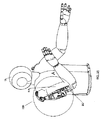
図面を参照すると、図1A〜図3は、ユーザUによって着用された適応腕支持システム10の例示の第1実施形態を示している。概して、(本明細書の他のシステムと同様の)システム10は、ハーネス12と、ユーザの片腕又は両腕を支持するための腕支持機構14(簡略化のために、ユーザの右腕RAを支持する1つの腕支持部14のみが示されている)と、を含んでいる。ハーネス12は、ユーザの胴体、例えば胸、ウエスト及び/又は腰の周りに着用されるように構成された取付バンド、ユーザの肩上に及び/又は肩の周りに着用されるように構成された肩ハーネス、及び/又は、例えば取付バンド及び肩ハーネスの間で延在する1以上の垂直支持部(明確化のためにすべて図示せず)、の1以上を含んでもよく、これらは、例えば、その開示の全体が参照によって本明細書に明示的に組み込まれる、米国特許出願公開第2012/0184880号、第2014/0033391号及び第2014/0158839号、並びに、国際公開第2015/2015/157473号に開示された支持システムと同様である。さらに、ハーネス12は、例えば腕支持部14を提供するためにシステム10の他の部品が結合され得るユーザの肩の上方に又は肩に隣接して配置された固定端を有する肩ブラケット及び/又はフレームを含んでもよく、腕支持部14は、それらの公報のシステムと同様に、肩ブラケットに対して1以上の軸回りで旋回する。本明細書のシステムは、必要に応じて、例えばアームレスト80のような、それらの公報で開示されたものと同様の追加部品を含んでもよい。
Referring to the drawings, FIGS. 1A-3 show an exemplary first embodiment of an adaptive
図1A及び図2Aは、アームレスト80を通じてユーザUの右腕RAに持ち上げ力を提供するように機能する適応腕支持システム10を示す斜視図である。腕支持システム10及び右腕RAが、図1Aに上げた状態で、図2Aに下ろした状態で示されている。概して、腕支持機構14は、垂直旋回軸20回りで水平に回転するように、ハーネス12に、例えばハーネス12上の固定肩ブラケット(図示せず)に旋回可能に結合された第1支持セグメント、部材すなわち肩バー22と、水平旋回軸28回りで垂直に回転するように肩バー22に旋回可能に結合された第2支持セグメント、部材すなわちシャーシ30と、を含んでいる。
1A and 2A are perspective views illustrating an adaptive
肩垂直旋回軸20は、実質的に垂直軸回りでの腕支持部14の回転を許容してもよい。例えば、肩バー22は、ハブ26に肩垂直旋回軸20を接続し、ハブ26は、肩バー22に固定的に装着されており、かつ、肩水平旋回軸28を含んでおり、実質的に水平軸回りのシャーシ30の回転を可能にする。シャーシ30は、例えばハウジング又はカートリッジ(内部部品の識別を容易にするために図示せず)内に収容された複数の部品のための装着構造を提供する。例えば、シャーシ30は、例えばばね、プーリ、ケーブル等の1以上の補償要素を含んでもよく、1以上の補償要素は、ユーザが動く際に腕RAに作用する重力を少なくとも部分的に相殺するための相殺力を付加し、例えば腕RAの向きに基づいて可変の相殺力を提供する。
The shoulder
例えば、図1B、図2B、図3A及び図3Bに示すように、シャーシ30は、第1プーリ40と、第1プーリ40に装着された第2プーリ42と、を含んでもよく、第1プーリ40及び第2プーリ42は、ともに結合されて1つになって動き、例えば軸44回りで回転する。第1張力要素、例えば第1ケーブル62が、第1プーリ40とハブ26上のアンカー点24とに取り付けられている。板ばね70の第1端が、片持ち取付具74でシャーシ30に取り付けられている。板ばね70の第2の自由端は、プーリハブ72に取り付けられており、プーリハブ72は移動軸54を含んでおり、この移動軸54回りでゼロ又は1以上の移動プーリ50が回転する。プーリ50は、張力要素の軌道又は溝52(図1Bで最もよく見える)を含んでもよい。1以上の固定プーリ56が、固定軸58回りで回転してもよく、かつ、張力要素の軌道又は溝53を含んでもよい。移動プーリ50及び固定プーリ56がともに、「滑車装置(block and tackle)」機構を形成し、この滑車装置機構によって、第2張力要素、例えば第2ケーブル66における力が、「滑車装置」内の第2張力要素66の巻き付きの数を増やすことによって増幅されて、及び従って、板ばね70を撓ませるように働く張力要素の数を有意に増加させ得る。第2張力要素66の第1端は、第2プーリ42に取り付けられ、(張力要素の溝52及び53それぞれ内の)移動プーリ50及び固定プーリ56の1以上の周りに巻き付く。第2張力要素66の第2端は、様々なポイントの1つで、例えば固定軸58に又は移動軸54に取り付けられてもよい。巻き付きの数は「滑車装置」の機械的利益を決定する。例えば、3つの固定プーリ56と2つの移動プーリ50とがあり、第2張力要素66が移動軸54で取り付けられる場合、「滑車装置」内には第2張力要素66の5つの有効な巻き付きがあり、5つの機械的利益を提供する。(例えば)第2張力要素66における張力が、所定のポイントで、15キログラム(15Kg)である場合、板ばね70を撓ませるように作用する力の総計は75キログラム(15×5=75Kg)になる。
For example, as shown in FIGS. 1B, 2B, 3A, and 3B, the
図2B及び図3Bは、図2Aに示すように、下ろされた腕RA及び腕支持部14を示す詳細である。ユーザUが右腕RAを下ろしたことに応答して、第1張力要素62は第1プーリ40から巻き解かれ、そして第1プーリ40及び第2プーリ42の両方が、それに応じて、軸44回りで(ともに)回転させられる。第2プーリ42が軸44回りで回転すると、第2張力要素66は第2プーリ42上でさらに巻き付けられる。このことが今度は、「滑車装置」内での第2張力要素66の巻き付きをきつくし、固定プーリ56のより近くに移動プーリ50を引き寄せ、そしてそれに応じて板ばね70を撓ませる。移動プーリ50が固定プーリ56のより近くに引き寄せられる距離は、第2張力要素66の有効な巻き付きの数によって提供される機械的利益の関数である。例えば、「滑車装置」内の第2張力要素66の5つの有効な巻き付きがある場合、移動プーリ50は、(第2プーリ42の周りに巻き付けられている場合の)第2張力要素66の長さの変化の約5分の1(1/5)にわたって固定プーリ56のより近くに引き寄せられる。
2B and 3B are details showing the arm RA and
図1B及び図3Aには、ユーザUの右腕RAが上げられて示されており、板ばね70が相対的に撓ませられておらず、かつ、移動プーリ50が固定プーリ56から切り離されている。この位置では、板ばね70は、右腕RAに持ち上げ力を提供し、この持ち上げ力は、第1プーリ40及び第2プーリ42の半径及びサイズを含む補償要素の部品の幾何学的形状の関数である。
1B and 3A, the right arm RA of the user U is shown in a raised state, the
図3Bでは、ユーザUの右腕RAがほぼ円弧A1に沿って下ろされて示されている。板ばね70は、相対的に撓ませられており、固定プーリ56に向かって引っ張られ、移動プーリ50は固定プーリ56のより近くにある。ほぼ経路P1に沿った右腕RAの動きに応じて実質的に撓ませられた板ばね70は、第2張力要素66により大きな力を必ず付与している。しかしながら、本明細書に参照によって組み込まれた出願における実施形態と同様に、板ばね70の増大した力を無効にして、及び従って、例えば「ばねを不利な状態にする」ことによって右腕RAへの持ち上げ力を調節するように機能する、第1プーリ40及び第2プーリ42の半径及びサイズを含む部品の幾何学的形状のために、第2張力要素66におけるより大きな力は、右腕RA上により大きな持ち上げ力を生成することができない。部品の幾何学的形状は、通常範囲の動きを通じた腕RAの移動中に右腕RAに適用される所望の力修正を実現するために、必要に応じて、変更されてもよいことが理解されよう。
In FIG. 3B, the right arm RA of the user U is shown to be lowered substantially along the arc A1. The
板ばね70は、様々な金属(例えば鋼鉄)、ポリマー(例えばポリアセタール)、エラストマー(例えばポリウレタン)、複合体(例えば炭素繊維構造)、及び/又は、天然材料(例えば木材又は竹)から構築されてもよい。
図4A〜図6Bを参照すると、適応腕支持システム100の別の実施形態が示されており、この適応腕支持システム100は、図1A〜図3Bの腕支持システム10を参照して説明した他の実施形態とほぼ同様であり、及び/又は、本明細書に参照によって組み込まれた出願で説明されるように、ハーネスと腕支持部とを含んでいる。腕支持システム100は、板ばね110が、図1A〜図3Bに示す板ばね70の撓みの方向にほぼ垂直な方向に撓ませられる点においてのみ、腕支持システム10と異なる。
Referring to FIGS. 4A-6B, another embodiment of an adaptive
図4Aは、右腕RA及び腕支持部が上げられた状態のシステム100を示している一方で、図5Aは右腕RAが下ろされた状態を示している。図4B及び図6Aは、図4Aのように腕支持部が上げられた状態の詳細である一方で、図5B及び図6Bは、図5Aのように腕支持部が下ろされた状態の詳細であり、腕支持部の補償要素の複数の部品を運ぶシャーシ105のさらなる詳細を提供している。
FIG. 4A shows the
特に、肩水平旋回軸28回りに回転するシャーシ105は、図1A〜図3Bからのシャーシ30がそうであったように、例えばともに結合されて1つになって軸44回りで回転する第1プーリ40及び第2プーリ42を含む複数の部品のための装着構造を提供する。第1張力要素又はケーブル62が、第1プーリ40に、かつ、ハブ26上のアンカー点24に取り付けられる。板ばね110の第1端は、片持ち取付具112でシャーシ105に取り付けられる。板ばね110の第2の自由端は、ゼロ又は1以上の移動プーリ120がその回りで回転する移動軸121を含むプーリハブ130に取り付けられる。1以上の固定プーリ115が、固定軸116回りで自由に回転する移動プーリ120に隣接してシャーシ105に装着される。
In particular, the
移動プーリ120及び固定プーリ115はともに「滑車装置」を形成し、それによって、第2張力要素又はケーブル124における力が、「滑車装置」内の第2張力要素124の巻き付きの数を増やすことによって増幅されてもよく、及び従って、板ばね110を撓ませるように働く張力要素の数を有意に増加させる。第2張力要素124の第1端は、第2プーリ42に取り付けられ、移動プーリ120及び固定プーリ115の1以上の周りに巻き付く。第2張力要素124の第2端は、例えば固定軸116に又は移動軸121に複数のポイントの1つで取り付けられてもよい。図1Bを参照して上で説明したように、巻き付きの数は「滑車装置」の機械的利益を決定する。例えば、3つの固定プーリ115と2つの移動プーリ120とがあり、かつ、張力要素が移動軸121で取り付けられる場合、「滑車装置」内に第2張力要素124の5つの有効な巻き付きが生じ、5つの機械的利益を提供する。例えば、第2張力要素124における張力が、所定のポイントで、15キログラム(15Kg)である場合、板ばね110を撓ませるように働く力の総計は75キログラム(15×5=75Kg)である。
The moving
図5B及び図6Bは、図5Aに示すようなシャーシ105の詳細である。ユーザUが右腕RAを下ろしたことに応答して、第1張力要素62は、第1プーリ40から巻き解かれ、それに応答して、第1プーリ40及び第2プーリ42が軸44回りでともに回転する。第2プーリ42が軸44回りで回転すると、第2張力要素124が第2プーリ42上にさらに巻き付けられる。このことが今度は、「滑車装置」内での第2張力要素124の巻き付きをきつくし、固定プーリ115のより近くに移動プーリ120を引き寄せ、それに応じて板ばね110を撓ませる。移動プーリ120が固定プーリ115のより近くに引き寄せられる距離は、第2張力要素124の有効な巻き付きの数によって提供される機械的利益の関数である。例えば、「滑車装置」内に第2張力要素124の5つの有効な巻き付きがある場合、移動プーリ120は、(第2プーリ42の周りに巻き付けられる場合の)第2張力要素66の長さの変化の約5分の1(1/5)だけ固定プーリ115のより近くに引き寄せられ得る。
5B and 6B are details of the
図6Aでは、右腕RAが上げられており、板ばね110は相対的に撓んでおらず、移動プーリ120が固定プーリ115から切り離されている。板ばね110は、第1プーリ40及び第2プーリ42の半径及びサイズを含む部品の幾何学的形状の関数である、右腕RAへの持ち上げ力を提供する。
In FIG. 6A, the right arm RA is raised, the
図6Bでは、右腕RAがほぼ円弧A2に沿って下ろされた状態で示されている。板ばね110は、相対的に撓ませられており、固定プーリ115に向かって引っ張られ、移動プーリ120は固定プーリ115のより近くにある。右腕RAの動きに応じて実質的に撓ませられた板ばね110は、経路P2にほぼ沿って、第2張力要素124により大きな力を付与する。しかしながら、例えば「ばねを不利な状態にする」ことによって板ばね110の増大した力を無効化して、及び従って、右腕RAへの持ち上げ力を調節するように機能する、第1プーリ40及び第2プーリ42の半径及びサイズを含む部品の幾何学的形状のため、第2張力要素124におけるより大きな力は、右腕RA上により大きな持ち上げ力を生成することができない。通常範囲の動きを通じた腕RAの動き中に右腕RAに付加される所望の力修正を実現するために、部品の幾何学的形状は、必要に応じて、変更されてもよいことが理解されよう。
In FIG. 6B, the right arm RA is shown in a state of being lowered substantially along the arc A2. The
前述の実施形態と同様に、板ばね110は、様々な材料及び/又は方法を用いて構築されてもよく、例えば1以上の金属(例えば鋼鉄)、ポリマー(例えばポリアセタール)、エラストマー(例えばポリウレタン)、複合体(例えば炭素繊維構造)、及び/又は、天然材料(例えば木材又は竹)から構築されてもよい。
Similar to the previous embodiments,
図7A〜図9Bを参照すると、本明細書で説明した他の実施形態及び参照により組み込まれた出願における他の実施形態とほぼ同様に、ハーネスと、ユーザの片腕又は両腕(右腕RAのみが示されている)を支持する腕支持部と、を含む適応腕支持システム200の別の実施形態が示されている。ハーネス及び肩ブラケットが明確化のために図示されていない。図7Aは、右腕RAが上げられて、腕支持部がアームレスト80を通じて右腕RAに持ち上げ力を提供するように機能している状態の腕支持システム200を示す斜視図である一方で、図8Aは、右腕RAが下ろされた状態を示している。
7A-9B, in much the same manner as other embodiments described herein and other embodiments in the applications incorporated by reference, the harness and one or both arms of the user (only the right arm RA is Is shown) and another embodiment of an adaptive
他の実施形態とは異なり、腕支持システム200は、単一の対称の例えば円形のプーリ230を含んでおり、このプーリ230は、位置を変化させる移動軸234回りで回転し、それによって、対称のプーリ230の位置を変化させ、肩バー22とシャーシ又はカートリッジ210との間の可変の相殺力を提供する。
Unlike other embodiments, the
図7B及び図9Aは、右腕RAが上げられた状態のシャーシ210の詳細であり、図8B及び図9Bは、右腕RAが下ろされた状態のシャーシ210の詳細であり、それによって、右腕RAが上げられる及び下ろされる際の補償要素の変化する構成を示している。
7B and 9A are details of the
他の実施形態のように、肩垂直旋回軸20は、実質的に垂直な軸回りの腕支持システム200の腕支持部の回転を許容してもよい。肩バー22は、肩水平旋回軸28を含むハブ214に肩垂直旋回軸20を接続し、本明細書の他の実施形態と同様に、実質的に水平な軸回りの回転を可能にする。シャーシ210は、肩水平旋回軸28回りで回転し、補償要素の複数の部品のための装着構造を提供する。例えば、ばね又は他の弾性要素220の第1端が、取付要素222を介してポスト224でシャーシ210に接続する。弾性要素220の第2端は、フック又は他の取付要素226を介して張力要素又はケーブル240に接続する。張力要素240は、プーリ230の周りに巻き付き、アンカー点244でハブ214に取り付けられる。プーリ230は、シャーシ210におけるスロット212に沿って並進移動し得る移動軸234回りで回転し、それによって、プーリ230の位置と、プーリ230及び肩水平旋回軸28の間の距離と、を変化させる。
As in other embodiments, the shoulder
カムプレート250は、ハブ214(及びその結果として肩バー22)に固定的に接続され、かつ、カムスロット254を含んでおり、カムスロット254の内部で移動軸234が並進移動し得る。以下に説明するように、カムスロット254は、シャーシ210のスロット212内で、移動軸234及び従ってプーリ230の並進移動を決定する。従って、プーリ230の位置を変化させることによって、弾性要素220の影響、及び従って、右腕RA上への持ち上げ力が制御され得る。例えば、弾性要素220が、図7B及び図9Aに示すように相対的に撓んでいない(すなわち、縮んでいる)場合、弾性要素220は、右腕RAに持ち上げ力を付加する能力をほとんど有していない。しかしながら、プーリ230の位置が、肩水平旋回軸28から相対的に遠くに同時にある場合、(アンカー点244でハブ214に取り付けられて、弾性要素220に力を伝達する)張力要素240の右腕RAへの影響が増大させられる。
The
ユーザUが右腕RAを下ろすことに応答して、図8A、図8B及び図9Bに示すように、カムスロット254によって案内される移動軸234が、シャーシ210のスロット212内で並進移動して、それによって、カムスロット254に対してプーリ230を並進移動させる。肩水平旋回軸28により近い(図7A、図7B及び図9Aのプーリ230の位置と対照して見た場合)プーリ230の位置は、より短いモーメントアーム(レバー)を生じさせ、その上で、張力要素240(及び従って、現在では伸びていて、及び従って、張力要素240により大きな力を付加する弾性要素220)が右腕RAに作用することができる。
In response to the user U lowering his right arm RA, the axis of
図9Aに示すように、右腕RAが上げられ、弾性要素220が相対的に撓んでおらず、(カムスロット254によって案内された移動軸234上で運ばれ、シャーシ210のスロット212内で並進移動した)プーリ230が、距離D1だけ肩水平旋回軸28から変位させられる。
As shown in FIG. 9A, the right arm RA is raised and the
図9Bでは、右腕RAが、ほぼ円弧A3に沿って下ろされて、弾性要素220が相対的に撓ませられる。カムスロット254によって案内された移動軸234は、経路P3に沿ってカムスロット254内で並進移動し、及び、経路P4に沿ってシャーシ210のスロット212内で並進移動する。移動軸234上で運ばれたプーリ230は、(図9Aの)距離D1より概して小さい距離D2だけ、肩水平旋回軸28から現在は変位させられる。肩水平旋回軸28のより近くの(図7A及び図7Bのプーリ230の位置と対照して見た場合)プーリ230の位置は、より短いモーメントアーム(レバー)を生じさせ、その上で、張力要素240(及び従って、現在では伸びていて、及び従って、張力要素240により大きな力を付加する弾性要素220)が右腕RAに作用することができる(それによって、「ばねを不利な状態にする」)。
In FIG. 9B, the right arm RA is lowered substantially along the arc A3, and the
カムスロット254は、必要に応じて、肩水平旋回軸27に対してプーリ230の位置を修正するように構成されてもよい。例えば、カムスロット254は、右腕RAが上げられて弾性要素220が相対的に小さな力を付加しているとき(それによって、右腕RAに作用する正味の持ち上げ力を増加させる)に肩水平旋回軸28からのプーリ230の距離を最大にし、かつ、右腕RAが下ろされて弾性要素220がより大きな力を付加している(それによって、右腕RAに作用する正味の持ち上げ力を減少させる)ときに肩水平旋回軸28からのプーリ230の距離を最小にするように形作られてもよい。カムスロット254の形状は様々な持ち上げ力プロファイルを生成し得る。所望の持ち上げプロファイルの一例は、右腕RAが上げられたときに作業オーバーヘッドと調和して持ち上げ力を最大にし、右腕RAが下ろされたときに、ユーザ側によって右腕RAにかかっているものと調和して低いレベルに持ち上げ力を減少させるものであってもよい。別の例では、カムスロット254は、特定の範囲の腕の位置を通じて一定の持ち上げ力を付加するが、その範囲を上回る又は下回る持ち上げを付加しないように構成されてもよい。多くの持ち上げプロファイルは、カムスロット254の形状を変更することによって実現され得る。
The
図10A〜図12Bを参照すると、適応腕支持システム300の別の例示の実施形態が示されており、この適応腕支持システム300は、ユーザUによって着用されるハーネスと、1つ又は2つの腕支持部(1つがユーザUの右腕RAを支持するように示されている)と、を概して含み、腕支持部は、例えば、本明細書の他の実施形態と同様に、肩ブラケット22と、1以上の補償要素を運ぶシャーシ320と、を含んでいる。図10Aは、右腕RAが上げられて示された状態でアームレスト80を通じて右腕RAに持ち上げ力を提供するように作用する腕支持システム300を示す斜視図である一方で、図11Aは、下ろされた右腕RAを示している。
10A-12B, another exemplary embodiment of an adaptive
他の実施形態と同様に、肩垂直旋回軸20は、実質的に垂直な軸回りで腕支持システム300の肩ブラケット22の回転を許容してもよい。例えば、肩バー22は、ハブ310に肩垂直旋回軸20を接続し、ハブ310は、実質的に水平な軸回りでシャーシ320の回転を可能にする肩水平旋回軸28を含み、一方で、弾性トーション要素350は、右腕RAに持ち上げ力を提供するように作用する。さらに、カムプレート340はハブ310に強固に取り付けられ、ハブ310は、移動軸356のための所望の曲線の経路を規定して、さらに以下に説明するように、右腕RAにトーション要素350によって付加された力を変更するカムスロット342を含んでいる。
Similar to other embodiments, the shoulder
シャーシ320及びカバー330は、1以上のスロット、例えば外側スロット334及び内側スロット322(図11Bに示す)を含んでもよく、当該スロット内で、移動軸356が、例えばカムプレート340のカムスロット342とともに並進移動して、以下に説明するように、右腕RAが上げられる及び下ろされる際に移動軸356の位置を変更する。
The
図10B及び図11Bは、図10A及び図11Aにそれぞれ対応する詳細であり、図12A及び図12Bは図10B及び図11Bの側面図をそれぞれ示しており、シャーシ320のカバー330が取り外されて補償要素の部品を示している。図12A及び図12Bで最も良く見える例示の一実施形態では、弾性トーション要素350が、脚部352、354を有するトーションばねである。代替的に、他の弾性要素、図13A〜図15Bに示すように、例えば引っ張りコイルばねが設けられてもよい。図12A及び図12Bで最も良く見えるように、ばね350の第1又は移動脚部352が、移動軸356のローラ360によって拘束され、及び/又は、ローラ360に結合され、ばね350の第2又は固定脚部354が、ハブ28によって拘束され及び/又はハブ28に結合される。
10B and 11B are details corresponding to FIGS. 10A and 11A, respectively, and FIGS. 12A and 12B are side views of FIGS. 10B and 11B, respectively, in which the
腕支持システム300の操作が図11A〜図12Bに示されている。例えば、ユーザUが右腕RAを下ろしたことに応答して、図11B及び図12Bに示すように、カムスロット344によって案内された移動軸356は、それとともにローラ360を運ぶシャーシ320及びカバー330のスロット322及び334内で並進する。肩水平旋回軸28により近い(図10B及び図12Aのローラ360の位置と対照して見た場合)ローラ360の位置は、より短いモーメントアーム(レバー)を生じさせ、その上で、弾性トーション要素350(現在では撓んでいて、及び従って、ローラ360により大きな力を付加する)が右腕RAに作用することができる(それによって、「ばねを不利な状態にする」)。
Operation of
図10B及び図12Aでは、右腕RAは上げられて示されており、弾性トーション要素350は相対的に撓んでおらず、(移動軸356上で運ばれ、及び従って、カムスロット344によって案内されてスロット322、334に沿って並進移動する)ローラ360は、距離D6だけ肩水平旋回軸28から変位させられる。ローラ360は、トーション要素350の中心312から距離D5で弾性トーション要素350の移動脚部352に接触する。トーション要素350の固定脚部354はハブ310に静止して接触する。
10B and 12A, the right arm RA is shown raised and the
図12Bでは、右腕RAが(ほぼ円弧A4に沿って)下ろされる。弾性トーション要素350は、(図12Aの上げられた位置での撓みと比べて)より撓ませられる。移動軸356は、カムスロット344内でほぼ経路P5に沿って移動し、カムスロット344の案内下でシャーシ320及びカバー330のスロット322、334内で、ほぼ経路P6に沿って並進移動する。移動軸356上で運ばれるローラ360は、距離D8だけ肩水平旋回軸28から変位させられ、トーション要素350の中心312から距離D7でトーション要素350の移動脚部352に接触する。距離D7は距離D5よりも大きいので、ローラ360は、上げられた位置でよりも下ろされた位置でトーション要素350上により大きな機械的利益を有している。距離D6は距離D8よりも大きいので、ローラ360は、上げられた位置のものよりも下ろされた位置でシャーシ320上により小さな機械的利益を有している。トーション要素350上へのローラ360のより大きな機械的利益とシャーシ320上へのローラ360のより小さな機械的利益との組み合わせは、(下ろされた位置での)トーション要素350の増加した捻れ力が右腕RA上への持ち上げ力を増加させることができないという結果をもたらした。
In FIG. 12B, the right arm RA is lowered (almost along the arc A4). The
カムスロット344のサイズ及び/又は形状は、必要に応じて、所望の持ち上げ力プロファイルを提供するためにカムスロット344に沿って移動する際にローラ360の位置を変更するように構成されてもよい。例えば、カムスロット344は、右腕RAが上げられて(例えば図10Aに示すように)、トーション要素350が相対的に小さな力を付加しているときに肩水平旋回軸28からのローラ360の距離を最大にし、かつ、右腕RAが下ろされて(例えば図11Aに示すように)、トーション要素350がより大きな力を付加しているときに肩水平旋回軸28からのローラ360の距離を最小にするように形作られてもよい。
The size and/or shape of the
所望の持ち上げプロファイルの一例は、右腕RAが上げられたときに、作業オーバーヘッドに調和して、又は、水平に完全に広げられたときに、持ち上げ力を最大にするように、かつ、右腕RAが、ユーザの側によって右腕RAにかかるものに調和して相対的に低いレベルに持ち上げ力を減少させるようなものであってもよい。別の例では、カムスロット344は、特定の範囲の腕位置を通じて一定の持ち上げ力を付加するが、その範囲を上回る又は下回る場合に力を付加しないように構成されてもよい。多くの持ち上げプロファイルが、カムスロット344の形状を変更することによって実現されてもよい。代替の実施形態では、システム300は、例えばシャーシ320上の既定の場所でローラ356を固定してカムプレート340を省略することによって、簡略化されてもよい。このことは、多少制御可能でなくなるが、旋回軸28からのローラ356の距離は、シャーシ320が上げられる及び下ろされる際に変化し、それによって、右腕RAに付加された持ち上げ力を調節し、例えば右腕RAが下ろされる際に持ち上げ力を減少させる。
An example of a desired lifting profile is to maximize lifting force when the right arm RA is raised, in harmony with work overhead, or when fully extended horizontally, and Alternatively, the lifting force may be reduced to a relatively low level in harmony with that applied to the right arm RA by the side of the user. In another example, the
図13A〜図15Bを参照すると、適応腕支持システム400のさらに別の例示の実施形態が示されている。図13Aは、腕支持部及び右腕RAが上げられた状態で、ユーザUの右腕RAにアームレスト80を通じて持ち上げ力を提供するように作用する腕支持システム400の斜視図である一方で、図14Aは、腕支持システム400及び右腕RAが下ろされた状態を示している。概して、システム400は、ユーザUによって着用されるハーネス(図示せず)と、ユーザUの右腕RAを支持する腕支持部と、を含み、腕支持部は、本明細書の他の実施形態と同様に、ハーネスに旋回可能に結合された肩ブラケット22と、肩ブラケット22に旋回可能に結合されて、1以上の補償要素を運ぶシャーシ320と、を含んでいる。
13A-15B, yet another exemplary embodiment of an adaptive
図13B、図14B、図15A及び図15Bは、(図示しないカバーが取り外された状態の)シャーシ420によって運ばれる補償要素、例えば、ばね又は他の弾性部材460、曲線形状軌道430、軌道430上を移動するように構成されたキャリッジ440の部品を示す詳細である。他の実施形態と同様に、肩垂直旋回軸20は、実質的に垂直な軸回りで腕支持システム400の回転を許容し、肩バー22は、肩水平旋回軸28を含むハブ410に肩垂直旋回軸20を接続し、実質的に水平な軸回りの回転を可能にする。シャーシ420は、肩水平旋回軸28回りで回転し、肩水平旋回軸28回りでシャーシ420とともに回転する形状軌道430のための装着構造を提供する。
13B, 14B, 15A and 15B show compensating elements carried by the chassis 420 (with the cover not shown removed), such as springs or other
キャリッジ440は、形状軌道430を辿る複数のローラ446のための装着具を提供し、必要に応じて、キャリッジ440が形状軌道430に沿って並進移動することを許容する。さらに、キャリッジ440は、弾性要素460の一端のための1以上の装着特徴、例えば、装着アーム450及び装着タブ454を含む。装着タブ454は、例えば、フック又は他の取付要素462を装着タブ454に結合することによって、弾性要素460の第1端のための取付点を提供する。弾性要素460の第2端は、例えば、フック又は他の取付要素468をハブ410上の取付点414に結合することによって、ハブ410に結合される。
The
図13B及び図14Bは、それぞれ図13A及び図14Aに対応する詳細であり、図15A及び図15Bはそれぞれ図13B及び図14Bの側面図を示している。図13B及び図15Aに示すように、腕支持部及びユーザUの右腕RAは上げられた状態で示されており、キャリッジ440は、形状軌道430の外側端430aに向かって配置される。図15Aは、相対的に伸びていない弾性要素460を示しており、及び従って、キャリッジ440に相対的に小さな力しか付加しない。しかしながら、キャリッジ440は、弾性要素460が肩水平旋回軸28から距離D9で作用するように軌道430の外側端430aに向かって配置されており、及び従って、弾性要素460は、右腕RAに適切な持ち上げ力を提供することができる。
13B and 14B are details corresponding to FIGS. 13A and 14A, respectively, and FIGS. 15A and 15B are side views of FIGS. 13B and 14B, respectively. As shown in FIGS. 13B and 15A, the arm support portion and the right arm RA of the user U are shown in a raised state, and the
図15Bは、ほぼ円弧A5に沿って下ろされたユーザUの右腕RAを示している。弾性要素460は相対的に伸ばされ、及び従って、キャリッジ440に相対的に大きな力を付加する。ユーザUが右腕RAを下ろしたことに応答して、キャリッジ440は、ほぼ円弧A6に沿って形状軌道430に沿って同時に移動し、軌道430の内側端430bのより近くまで、及び従って、肩水平旋回軸28のより近くまで移動する。同時に、弾性要素460が伸びて、肩水平旋回軸28から距離D10で作用し、装着タブ454とハブ410上の取付点414により力を作用させる。D9はD10よりも大きいため、伸びた弾性要素460は、より小さな機械的利益で作用し、及び従って、右腕RAに過度の持ち上げ力を提供しない(再びそれによって、「ばねを不利な状態にする」)。形状軌道430の形状及び/又は位置は、前述したカムスロット344と同様に、上に及び下に移動する際に右腕RAに所望のプロファイルの持ち上げ力を提供するように、必要に応じて、修正されてもよい。
FIG. 15B shows the right arm RA of the user U lowered substantially along the arc A5. The
図16A〜図18Bを参照すると、適応腕支持システム500のさらに別の例示の実施形態が示されており、この適応腕支持システム500は、右腕RAが上げられる及び下げられる際に、アームレスト80を通じてユーザUの右腕RAに持ち上げ力を提供するように作用する。図16Aでは、腕支持システム500及び右腕RAが上げられて示されている一方で、図17Aでは、腕支持システム及び右腕RAは下ろされて示されている。概して、システム500は、ユーザUによって着用されるハーネス(図示せず)と、ユーザUの片腕又は両腕を支持する腕支持部と、を含み、腕支持部は、本明細書の他の実施形態と同様に、ハーネスに旋回可能に結合された肩ブラケット22と、肩ブラケット22に旋回可能に結合されて、1以上の補償要素を運ぶシャーシ510と、を含む。
16A-18B, yet another exemplary embodiment of an adaptive
前述の実施形態とは異なり、腕支持部500は、例えばケーブル566等の張力要素の取付点の場所を変化させて右腕RAへの持ち上げ力を調節するために、対称の例えば円形の1対のプーリ530、536と、曲線形状軌道544と、キャリッジ548と、を採用する。例えばフレーム、肩中心ジンバル及びハーネス等の他の上で開示した部品は明確化のために図示されていない。例えば、他の実施形態と同様に、肩垂直旋回軸20が、実質的に垂直な軸回りで腕支持システム500の回転を許容してもよく、肩バー22がハブ520に肩垂直旋回軸20を接続し、ハブ520は、肩水平旋回軸28を含み、実質的に水平な軸回りでの回転を可能にする。
Unlike the previous embodiments, the
肩水平旋回軸28回りで回転するシャーシ510は複数の部品のための装着構造を提供する。例えば、引っ張りコイルばね又は他の弾性要素560が、シャーシ510とハブ520との間に結合されて右RAに所望の持ち上げ力を付加する。図示するように、弾性要素560の第1端は、ポスト514で、例えばフック又は他の取付要素562を介してシャーシ510に接続される。弾性要素560の第2端は、例えばフック又は他の取付要素564を介して張力要素644に接続する。肩水平旋回軸28回りで回転するシャーシ510は、(肩水平旋回軸28回りでそれとともに回転する)形状軌道544のための装着構造を提供する。
A
キャリッジ548は、形状軌道544を辿る複数のローラ550のための装着構造を提供し、必要に応じて形状軌道544に沿ってキャリッジ548が並進移動することを許容する。第1プーリ530は、肩水平旋回軸28とほぼ同心でハブ520内に装着され、第2プーリ536は、軸538でハブ520内に装着される。張力要素560は、第1プーリ538の周りに少なくとも部分的に巻き付き、第2プーリ536はアンカー点552でキャリッジ548に取り付けられる。
The
図18Aは、弾性要素560が相対的に伸びておらず、及び従って、張力要素566に及び従ってキャリッジ548の取付点538に、相対的に小さな力を付与する。しかしながら、キャリッジ548は、弾性要素566が肩水平旋回軸28から距離D11で作用するように形状軌道544の外側端544aに向かって配置され、及び従って、弾性要素566は、右腕RAに適切な持ち上げ力を提供することができる。
FIG. 18A shows that the
図17B及び図18Bで最も良く見えるように、ユーザUが右腕RAを下ろしたことに応答して、キャリッジ548は形状軌道544に沿って移動し、肩水平旋回軸28の近くに移動する一方で、弾性要素560が同時に伸び、トーション要素560により力を作用させる。図18Bは、ユーザの右腕RAがほぼ円弧A7に沿って下ろされた状態を示している。弾性要素566が相対的に伸び、及び従って、張力要素566に及び従ってキャリッジ548の取付点538に、相対的に大きな力を付加する。キャリッジ548は、形状軌道544の内側端544bに向かって、ほぼ円弧A8に沿って、形状軌道544に沿って同時に移動し、弾性要素566は、肩水平旋回軸28から距離D12で作用する。D11はD12よりも大きく、伸びた弾性要素566はより小さな機械的利益で作用し、及び従って、右腕RAに過度の持ち上げ力を提供することはない(再びそれによって「ばねを不利な状態にする」)。形状軌道430の形状及び/又は位置は、右腕RAへの所望のプロファイルの持ち上げ力を実現するために、必要に応じて、修正されることが可能である。
As best seen in FIGS. 17B and 18B, in response to the user U lowering his right arm RA, the
本明細書の任意の実施形態とともに示された要素又は部品が、特定の実施形態のための単なる例示であり、本明細書で開示された他の実施形態に又は他の実施形態と組み合わせて用いられてもよいことが理解されよう。 The elements or components shown with any embodiment herein are merely exemplary for the particular embodiment and are used with or in combination with other embodiments disclosed herein. It will be appreciated that it may be done.
本発明は、様々な変更及び代替の形状を受け入れることが可能であり、その特定の例が、図面に示されており、かつ、本明細書で詳細に説明されている。しかしながら、本発明は、開示された特定の形状や方法に限定されるものではないが、反対に、本発明は、添付の特許請求の範囲の範囲内に属するすべての変形例、均等物及び代替例をカバーすることが理解されるべきである。 The present invention is capable of accepting various modifications and alternative forms, specific examples of which are shown in the drawings and described in detail herein. However, the invention is not limited to the particular shapes and methods disclosed, but on the contrary the invention is intended to cover all modifications, equivalents and alternatives falling within the scope of the appended claims. It should be understood to cover the examples.
Claims (25)
ユーザの身体に着用されるように構成されたハーネスと、
第1腕支持セグメントであって、前記第1腕支持セグメントが前記ハーネスに対して第1垂直軸回りで実質的に水平に回転可能であるように前記第1垂直軸回りで前記ハーネスに旋回可能に結合された第1腕支持セグメントと、第2腕支持セグメントであって、前記第2腕支持セグメントが、前記第1垂直軸にほぼ直交する第2軸回りで回転可能であるようにハブで前記第1腕支持セグメントに旋回可能に結合された第2腕支持セグメント、を備える腕支持部と、
前記ユーザが動いて前記腕支持部が前記ユーザの腕の動きに追従する際に前記腕に作用する重力を少なくとも部分的に相殺するための相殺力を付加するための1以上の補償要素であって、前記1以上の補償要素は、
前記ハブに固定的に結合されて、曲線の軌道を含むカムプレートと、
シャーシのシャーシスロット内にスライド可能に装着された移動軸であって、前記第2腕支持セグメントが上げられる及び下ろされる際に前記移動軸が前記軌道に沿って前記シャーシスロット内で移動するように、前記カムプレートの前記軌道内にスライド可能に配置される移動軸と、
第1固定端と、前記相殺力が、前記移動軸が前記軌道に沿って前記第2軸から離れるように移動する際に増加し、前記移動軸が前記軌道に沿って前記第2軸に向かって移動する際に減少するように、前記移動軸に結合された第2端と、を含むばねと、を備える1以上の補償要素と、を備え、
前記ばねは、前記シャーシに装着された前記第1固定端を有する引っ張りコイルばねであり、前記システムは、
前記移動軸に回転可能に装着されたプーリと、
前記プーリの周りに少なくとも部分的に巻き付けられたトーション要素であって、前記ばねの前記第2端に結合された第1端と、前記ハブに結合された第2端と、を含み、前記第2腕支持セグメントが下ろされる際、前記プーリは、前記移動軸が前記軌道に沿って前記第2軸に向かって移動して、前記トーション要素によって付加された前記相殺力を低減し、かつ、前記第2腕支持セグメントが上げられる際、前記プーリは、前記移動軸が前記軌道に沿って前記第2軸から離れるように移動して、前記トーション要素によって付加された前記相殺力を増加させる、トーション要素と、をさらに備えるシステム。 A system for supporting a user's arm,
A harness configured to be worn on a user's body,
A first arm support segment, pivotable to the harness about the first vertical axis such that the first arm support segment is rotatable substantially horizontally about a first vertical axis with respect to the harness. A first arm support segment and a second arm support segment coupled to the second arm support segment at a hub such that the second arm support segment is rotatable about a second axis substantially orthogonal to the first vertical axis. An arm support part comprising a second arm support segment pivotably coupled to the first arm support segment,
One or more compensating elements for adding a canceling force for at least partially canceling the gravity acting on the arm when the user moves and the arm support portion follows the movement of the arm of the user. And the one or more compensation elements are
A cam plate fixedly coupled to the hub and including a curved track;
A moving shaft which is slidably mounted in the chassis of the chassis slot, so that the moving shaft when the second arm support segments is lowered and raised is moved in said chassis slot along said track A moving shaft slidably disposed within the track of the cam plate;
The first fixed end and the offsetting force increase as the movement axis moves away from the second axis along the track, and the movement axis moves toward the second axis along the track. One or more compensating elements comprising: a spring including a second end coupled to the axis of movement so as to decrease when moving .
The spring is a tension coil spring having the first fixed end attached to the chassis, and the system is
A pulley rotatably mounted on the moving shaft,
A torsion element at least partially wrapped around the pulley, the torsion element including a first end coupled to the second end of the spring and a second end coupled to the hub; When the two-arm support segment is lowered, the pulley moves the movement axis along the trajectory toward the second axis to reduce the offsetting force exerted by the torsion element, and When the second arm support segment is raised, the pulley moves the movement axis along the track away from the second axis to increase the counteracting force exerted by the torsion element. A system further comprising:
ユーザの身体に着用されるように構成されたハーネスと、
前記ハーネスに結合されて、前記ユーザの腕を支持するように構成され、かつ前記腕の動きに適合する一方で、前記動きに追従するように構成された腕支持部であって、前記ユーザの上腕を支持するように構成され、前記ユーザの腕が上げられる及び下げられる際に動きに追従するよう旋回軸回りで旋回可能な腕支持セグメント、を備える腕支持部と、
前記ユーザが動いて前記腕支持部が前記ユーザの腕の動きに追従する際に、前記腕に作用する重力を少なくとも部分的に相殺するための相殺力を付加する1以上の補償要素であって、
前記腕支持セグメントに固定的に結合されて、カムスロットを含むカムプレートと、
移動軸であって、前記腕支持セグメントが上げられる及び下げられる際に前記移動軸が前記カムスロットに沿って移動するように前記カムスロット内にスライド可能に装着された移動軸と、
前記腕支持セグメントに固定された第1端と、前記相殺力が、前記移動軸が前記カムスロットに沿って前記旋回軸から離れるように移動する際に増加し、前記移動軸が前記カムスロットに沿って前記旋回軸に向かって移動する際に減少するように、前記移動軸に結合された第2端と、を含むばねと、を備える1以上の補償要素と、を備え、
前記カムスロットは、前記腕支持セグメントが下げられる際に前記移動軸を前記旋回軸に近づけ、前記腕支持セグメントが上げられる際に前記移動軸を前記旋回軸から遠ざけるように構成された、所定の形状を有する曲線の軌道を規定するシステム。 A system for supporting a user's arm,
A harness configured to be worn on a user's body,
An arm supporting unit that is coupled to the harness and configured to support the arm of the user, and that is adapted to follow the movement of the arm while being adapted to follow the movement of the user. An arm support portion configured to support an upper arm, and an arm support segment including an arm support segment that can be swiveled about a swivel axis so as to follow a movement when the user's arm is raised and lowered.
One or more compensating elements that add a canceling force for at least partially canceling the gravity acting on the arm when the user moves and the arm support portion follows the movement of the arm of the user. ,
A cam plate fixedly coupled to the arm support segment and including a cam slot;
A moving shaft slidably mounted within the cam slot such that the moving shaft moves along the cam slot when the arm support segment is raised and lowered.
The first end fixed to the arm support segment and the counteracting force increase as the moving shaft moves along the cam slot away from the pivot shaft, and the moving shaft moves into the cam slot. One or more compensating elements comprising: a spring including a second end coupled to the axis of movement so as to decrease as it travels toward the axis of rotation ;
The cam slot is configured to move the axis of movement closer to the pivot axis when the arm support segment is lowered and to move the axis of movement away from the pivot axis when the arm support segment is raised. A system that defines the trajectory of a curved line having a shape.
ユーザの身体に着用されるように構成されたハーネスと、
前記ハーネスに結合されて、前記ユーザの腕を支持するように構成され、かつ前記腕の動きに適合する一方で、前記動きに追従するように構成された腕支持部であって、前記ユーザの上腕を支持するように構成され、前記ユーザの腕が上げられる及び下げられる際に動きに追従するよう旋回軸回りで旋回可能な腕支持セグメント、を備える腕支持部と、
前記ユーザが動いて前記腕支持部が前記ユーザの腕の動きに追従する際に、前記腕に作用する重力を少なくとも部分的に相殺するための相殺力を付加する1以上の補償要素であって、
前記腕支持セグメントに固定的に結合されて、カムスロットを含むカムプレートと、
移動軸であって、前記腕支持セグメントが上げられる及び下げられる際に前記移動軸が前記カムスロットに沿って移動するように前記カムスロット内にスライド可能に装着された移動軸と、
前記腕支持セグメントに固定された第1端と、前記相殺力が、前記移動軸が前記カムスロットに沿って前記旋回軸から離れるように移動する際に増加し、前記移動軸が前記カムスロットに沿って前記旋回軸に向かって移動する際に減少するように、前記移動軸に結合された第2端と、を含むばねと、を備える1以上の補償要素と、を備え、
前記ばねは、前記腕支持セグメントに装着された前記第1端を有するトーションばねを備え、前記第2端は、前記移動軸が前記カムスロットに沿って前記旋回軸に向かって移動する際に前記相殺力が低減され、前記移動軸が前記旋回軸から離れるように移動する際に前記相殺力が増大されるように、前記移動軸に結合されるシステム。 A system for supporting a user's arm,
A harness configured to be worn on a user's body,
An arm supporting unit that is coupled to the harness and configured to support the arm of the user, and that is adapted to follow the movement of the arm while being adapted to follow the movement of the user. An arm support portion configured to support an upper arm, and an arm support segment including an arm support segment that can be swiveled about a swivel axis so as to follow a movement when the user's arm is raised and lowered.
One or more compensating elements that add a canceling force for at least partially canceling the gravity acting on the arm when the user moves and the arm support portion follows the movement of the arm of the user. ,
A cam plate fixedly coupled to the arm support segment and including a cam slot;
A moving shaft slidably mounted within the cam slot such that the moving shaft moves along the cam slot when the arm support segment is raised and lowered.
The first end fixed to the arm support segment and the counteracting force increase as the moving shaft moves along the cam slot away from the pivot shaft, and the moving shaft moves into the cam slot. One or more compensating elements comprising: a spring including a second end coupled to the axis of movement so as to decrease as it travels toward the axis of rotation;
The spring comprises a torsion spring having the first end mounted to the arm support segment, the second end being adapted to move the movement axis along the cam slot toward the pivot axis. A system coupled to the displacement axis such that the offset force is reduced and the offset force is increased as the displacement axis moves away from the pivot axis .
ユーザの身体に着用されるように構成されたハーネスと、
前記ハーネスに結合されて、前記ユーザの腕を支持するように構成され、かつ前記腕の動きに適合する一方で、前記動きに追従するように構成された腕支持部であって、前記ユーザの上腕を支持するように構成され、前記ユーザの腕が上げられる及び下げられる際に動きに追従するよう旋回軸回りで旋回可能な腕支持セグメント、を備える腕支持部と、
前記ユーザが動いて前記腕支持部が前記ユーザの腕の動きに追従する際に、前記腕に作用する重力を少なくとも部分的に相殺するための相殺力を付加する1以上の補償要素であって、
前記腕支持セグメントに固定的に結合されて、カムスロットを含むカムプレートと、
移動軸であって、前記腕支持セグメントが上げられる及び下げられる際に前記移動軸が前記カムスロットに沿って移動するように前記カムスロット内にスライド可能に装着された移動軸と、
前記腕支持セグメントに固定された第1端と、前記相殺力が、前記移動軸が前記カムスロットに沿って前記旋回軸から離れるように移動する際に増加し、前記移動軸が前記カムスロットに沿って前記旋回軸に向かって移動する際に減少するように、前記移動軸に結合された第2端と、を含むばねと、を備える1以上の補償要素と、を備え、
前記カムスロットは、前記腕支持セグメントが上げられる際に前記移動軸を前記旋回軸から遠ざけて、前記ばねにより前記腕支持セグメントに加えらえるばね力のモーメントアームを増加させて、前記相殺力を増加させ、前記腕支持セグメントが下ろされる際に前記移動軸を前記旋回軸から近づけて、前記ばね力のモーメントアームを減少させて、前記相殺力を低減させるように構成された、所定の形状を有する曲線の軌道を規定するシステム。 A system for supporting a user's arm,
A harness configured to be worn on a user's body,
An arm supporting unit that is coupled to the harness and configured to support the arm of the user, and that is adapted to follow the movement of the arm while being adapted to follow the movement of the user. An arm support portion configured to support an upper arm, and an arm support segment including an arm support segment that can be swiveled about a swivel axis so as to follow a movement when the user's arm is raised and lowered.
One or more compensating elements that add a canceling force for at least partially canceling the gravity acting on the arm when the user moves and the arm support portion follows the movement of the arm of the user. ,
A cam plate fixedly coupled to the arm support segment and including a cam slot;
A moving shaft slidably mounted within the cam slot such that the moving shaft moves along the cam slot when the arm support segment is raised and lowered.
The first end fixed to the arm support segment and the counteracting force increase as the moving shaft moves along the cam slot away from the pivot shaft, and the moving shaft moves into the cam slot. One or more compensating elements comprising: a spring including a second end coupled to the axis of movement so as to decrease as it travels toward the axis of rotation;
The cam slot moves the movement axis away from the pivot axis when the arm support segment is raised to increase a moment arm of a spring force applied to the arm support segment by the spring to increase the canceling force. A predetermined shape that is configured to increase and move the movement axis closer to the pivot axis when the arm support segment is lowered to reduce the moment arm of the spring force and reduce the offsetting force. A system that defines the trajectory of a curve that has.
ユーザの身体に着用されるように構成されたハーネスと、
前記ハーネスに結合されて、前記ユーザの腕を支持するように構成され、かつ前記腕の動きに適合する一方で、前記動きに追従するように構成された腕支持部であって、前記ユーザの上腕を支持するように構成され、前記ユーザの腕が上げられる及び下げられる際に動きに追従するよう旋回軸回りで旋回可能な腕支持セグメント、を備える腕支持部と、
前記ユーザが動いて前記腕支持部が前記ユーザの腕の動きに追従する際に、前記腕に作用する重力を少なくとも部分的に相殺するための相殺力を付加する1以上の補償要素であって、
前記腕支持セグメントに固定的に結合されて、カムスロットを含むカムプレートと、
移動軸であって、前記腕支持セグメントが上げられる及び下げられる際に前記移動軸が前記カムスロットに沿って移動するように前記カムスロット内にスライド可能に装着された移動軸と、
前記腕支持セグメントに固定された第1端と、前記相殺力が、前記移動軸が前記カムスロットに沿って前記旋回軸から離れるように移動する際に増加し、前記移動軸が前記カムスロットに沿って前記旋回軸に向かって移動する際に減少するように、前記移動軸に結合された第2端と、を含むばねと、を備える1以上の補償要素と、を備え、
前記カムスロットは、前記腕支持セグメントが所定の腕位置より上方に上げられるときに前記ばねに一定の相殺力を付加させ、前記腕支持セグメントが前記所定の腕位置より下に下ろされるときに前記相殺力を低減させるように構成された、所定の形状を有する曲線の軌道を規定するシステム。 A system for supporting a user's arm,
A harness configured to be worn on a user's body,
An arm supporting unit that is coupled to the harness and configured to support the arm of the user, and that is adapted to follow the movement of the arm while being adapted to follow the movement of the user. An arm support portion configured to support an upper arm, and an arm support segment including an arm support segment that can be swiveled about a swivel axis so as to follow a movement when the user's arm is raised and lowered.
One or more compensating elements that add a canceling force for at least partially canceling the gravity acting on the arm when the user moves and the arm support portion follows the movement of the arm of the user. ,
A cam plate fixedly coupled to the arm support segment and including a cam slot;
A moving shaft slidably mounted within the cam slot such that the moving shaft moves along the cam slot when the arm support segment is raised and lowered.
The first end fixed to the arm support segment and the counteracting force increase as the moving shaft moves along the cam slot away from the pivot shaft, and the moving shaft moves into the cam slot. One or more compensating elements comprising: a spring including a second end coupled to the axis of movement so as to decrease as it travels toward the axis of rotation;
The cam slot applies a constant offsetting force to the spring when the arm support segment is raised above a predetermined arm position, and when the arm support segment is lowered below the predetermined arm position. A system for defining a curved trajectory having a predetermined shape, configured to reduce offsetting forces.
ユーザの身体に着用されるように構成されたハーネスと、
前記ハーネスに結合されて、前記ユーザの腕を支持するように構成され、かつ前記腕の動きに適合する一方で、前記動きに追従するように構成された腕支持部であって、前記ユーザの上腕を支持するように構成され、前記ユーザの腕が上げられる及び下げられる際に動きに追従するよう旋回軸回りで旋回可能な腕支持セグメント、を備える腕支持部と、
前記ユーザが動いて前記腕支持部が前記ユーザの腕の動きに追従する際に、前記腕に作用する重力を少なくとも部分的に相殺するための相殺力を付加する1以上の補償要素であって、
前記腕支持セグメントに固定的に結合されて、カムスロットを含むカムプレートと、
移動軸であって、前記腕支持セグメントが上げられる及び下げられる際に前記移動軸が前記カムスロットに沿って移動するように前記カムスロット内にスライド可能に装着された移動軸と、
前記腕支持セグメントに固定された第1端と、前記相殺力が、前記移動軸が前記カムスロットに沿って前記旋回軸から離れるように移動する際に増加し、前記移動軸が前記カムスロットに沿って前記旋回軸に向かって移動する際に減少するように、前記移動軸に結合された第2端と、を含むばねと、を備える1以上の補償要素と、を備え、
前記ばねは、前記腕支持セグメントに装着された第1端を有する引っ張りコイルばねを備え、前記システムは、
前記移動軸に回転可能に装着されたプーリと、
前記プーリの周りに少なくとも部分的に巻き付けられた張力要素であって、前記ばねの前記第2端に結合された第1端と、前記腕支持セグメントに結合された第2端と、を含み、前記腕支持セグメントが下ろされるとき、前記移動軸が前記カムスロットに沿って前記旋回軸に向かって移動する際に前記プーリが前記旋回軸に向かって移動して、前記腕支持セグメントに付加される前記相殺力を低減させ、前記腕支持セグメントが上げられるとき、前記移動軸が前記カムスロットに沿って前記旋回軸から離れるように移動する際に前記プーリが前記旋回軸から離れるように移動して、前記腕支持セグメントに付加される前記相殺力を増加させる、張力要素と、をさらに備えるシステム。 A system for supporting a user's arm,
A harness configured to be worn on a user's body,
An arm supporting unit that is coupled to the harness and configured to support the arm of the user, and that is adapted to follow the movement of the arm while being adapted to follow the movement of the user. An arm support portion configured to support an upper arm, and an arm support segment including an arm support segment that can be swiveled about a swivel axis so as to follow a movement when the user's arm is raised and lowered.
One or more compensating elements that add a canceling force for at least partially canceling the gravity acting on the arm when the user moves and the arm support portion follows the movement of the arm of the user. ,
A cam plate fixedly coupled to the arm support segment and including a cam slot;
A moving shaft slidably mounted within the cam slot such that the moving shaft moves along the cam slot when the arm support segment is raised and lowered.
The first end fixed to the arm support segment and the counteracting force increase as the moving shaft moves along the cam slot away from the pivot shaft, and the moving shaft moves into the cam slot. One or more compensating elements comprising: a spring including a second end coupled to the axis of movement so as to decrease as it travels toward the axis of rotation;
The spring comprises a tension coil spring having a first end mounted to the arm support segment, the system comprising:
A pulley rotatably mounted on the moving shaft,
A tension element at least partially wrapped around the pulley, the tension element including a first end coupled to the second end of the spring and a second end coupled to the arm support segment; When the arm support segment is lowered, the pulley moves toward the pivot axis and is added to the arm support segment when the moving shaft moves toward the pivot axis along the cam slot. When the arm support segment is raised, the offset force is reduced, and the pulley moves away from the pivot axis when the movement axis moves away from the pivot axis along the cam slot. the increase the canceling force applied to the arm support segments, further comprising the system and the tension element, the.
ユーザの身体に着用されるように構成されたハーネスと、
第1腕支持セグメントであって、前記第1腕支持セグメントが前記ハーネスに対して第1垂直軸回りで実質的に水平に回転可能であるように前記第1垂直軸回りで前記ハーネスに旋回可能に結合された第1腕支持セグメントと、第2腕支持セグメントであって、前記第2腕支持セグメントが、前記第1垂直軸にほぼ直交する第2軸回りで回転可能であるようにハブで前記第1腕支持セグメントに旋回可能に結合された第2腕支持セグメント、を備える腕支持部と、
前記ユーザが動いて前記腕支持部が前記ユーザの腕の動きに追従する際に前記腕に作用する重力を少なくとも部分的に相殺するための相殺力を付加するための1以上の補償要素であって、
前記第2腕支持セグメントに装着された曲線の軌道と、
前記第2腕支持セグメントが上げられる及び下ろされる際に前記移動軸が前記軌道に沿ってシャーシスロット内で移動するように前記軌道上で運ばれるキャリッジと、
前記ハブに結合された第1端と、前記キャリッジが前記軌道に沿って移動する際に前記相殺力が変化するように前記キャリッジに結合された第2端と、を含むばねと、を備える1以上の補償要素と、を備えるシステム。 A system for supporting a user's arm,
A harness configured to be worn on a user's body,
A first arm support segment, pivotable to the harness about the first vertical axis such that the first arm support segment is rotatable substantially horizontally about a first vertical axis with respect to the harness. A first arm support segment and a second arm support segment coupled to the second arm support segment at a hub such that the second arm support segment is rotatable about a second axis substantially orthogonal to the first vertical axis. An arm support part comprising a second arm support segment pivotably coupled to the first arm support segment,
One or more compensating elements for adding a canceling force for at least partially canceling the gravity acting on the arm when the user moves and the arm support portion follows the movement of the arm of the user. hand,
A curved orbit attached to the second arm support segment,
A carriage carried on the track such that the movement axis moves within the chassis slot along the track when the second arm support segment is raised and lowered.
A spring including a first end coupled to the hub and a second end coupled to the carriage such that the offsetting force changes as the carriage moves along the track. A system comprising the above compensation element.
ユーザの身体に装着されるように構成されたハーネスと、
第1腕支持セグメントであって、前記第1腕支持セグメントが前記ハーネスに対して第1垂直軸回りで実質的に水平に回転可能であるように前記第1垂直軸回りで前記ハーネスに旋回可能に結合された第1腕支持セグメントと、第2腕支持セグメントであって、前記第2腕支持セグメントが、前記第1垂直軸にほぼ直交する第2軸回りで回転可能であるようにハブで前記第1腕支持セグメントに旋回可能に結合された第2腕支持セグメント、を備える腕支持部と、
前記ユーザが動いて前記腕支持部が前記ユーザの腕の動きに追従する際に前記腕に作用する重力を少なくとも部分的に相殺するための相殺力を付加する1以上の補償要素であって、
前記第2軸で前記ハブに回転可能に装着された第1プーリと、
前記第2軸からずれて前記ハブに回転可能に装着された第2プーリと、
前記第2腕支持セグメントに装着された曲線の軌道と、
前記第2腕支持セグメントが上げられる及び下げられる際に前記軌道に沿ってシャーシスロット内で前記移動軸が移動するように前記軌道上で運ばれるキャリッジと、
前記第2腕支持セグメントに結合された第1固定端と、第2移動可能端と、を含むばねと、
前記ばねの前記第2移動可能端と前記キャリッジとの間で結合された張力要素であって、前記キャリッジが前記軌道に沿って移動する際に前記相殺力が変化するように前記第1及び第2プーリの周りに少なくとも部分的に巻き付けられた張力要素と、を備える1以上の補償要素と、を備えるシステム。 A system for supporting a user's arm,
A harness configured to be worn on the user's body,
A first arm support segment, pivotable to the harness about the first vertical axis such that the first arm support segment is rotatable substantially horizontally about a first vertical axis with respect to the harness. A first arm support segment and a second arm support segment coupled to the second arm support segment at a hub such that the second arm support segment is rotatable about a second axis substantially orthogonal to the first vertical axis. An arm support part comprising a second arm support segment pivotably coupled to the first arm support segment,
One or more compensating elements that add a canceling force for at least partially canceling the gravity acting on the arm when the user moves and the arm support portion follows the movement of the arm of the user,
A first pulley rotatably mounted on the hub about the second shaft;
A second pulley rotatably mounted on the hub, offset from the second axis;
A curved orbit attached to the second arm support segment,
A carriage carried on the track for moving the axis of movement within the chassis slot along the track as the second arm support segment is raised and lowered;
A spring including a first fixed end coupled to the second arm support segment and a second movable end;
A tension element coupled between the second movable end of the spring and the carriage, the first and the first so that the counteracting force changes as the carriage moves along the track. A tensioning element at least partially wrapped around two pulleys, and one or more compensating elements.
ユーザの身体に着用されるように構成されたハーネスと、
第1腕支持セグメントであって、前記第1腕支持セグメントが前記ハーネスに対して第1垂直軸回りで実質的に水平に回転可能であるように前記第1垂直軸回りで前記ハーネスに旋回可能に結合された第1腕支持セグメントと、第2腕支持セグメントであって、前記第2腕支持セグメントが、前記第1垂直軸にほぼ直交する第2軸回りで回転可能であるようにハブで前記第1腕支持セグメントに旋回可能に結合された第2腕支持セグメント、を備える腕支持部と、
前記ユーザが動いて前記腕支持部が前記ユーザの腕の動きに追従する際に前記腕に作用する重力を少なくとも部分的に相殺するための相殺力を付加するために前記第2腕支持セグメントのシャーシによって支えられた1以上の補償要素であって、
前記シャーシに装着された第1固定端と、第2自由端と、を含む板ばねと、
前記板ばねの前記第2自由端に隣接して前記シャーシに回転可能に装着された1以上のシャーシプーリと、
第1及び第2結合プーリがともに回転するように前記シャーシに回転可能に装着された第1及び第2結合プーリと、
前記1以上のシャーシプーリの周りに少なくとも部分的に巻き付けられた第1張力要素であって、前記板ばねの前記第2自由端に結合された第1端と、前記第1結合プーリに結合された第2端と、を含む第1張力要素と、
前記第2結合プーリに結合された第1端と、前記ハブに結合された第2端と、を含む第2張力要素であって、前記1以上の補償要素は、前記ユーザが動いて前記腕支持部が前記ユーザの腕の動きに追従する際に前記腕に作用する重力を少なくとも部分的に相殺する相殺力を前記ハブに提供するように構成される、第2張力要素と、を備える1以上の補償要素と、を備えるシステム。 A system for supporting a user's arm,
A harness configured to be worn on a user's body,
A first arm support segment, pivotable to the harness about the first vertical axis such that the first arm support segment is rotatable substantially horizontally about a first vertical axis with respect to the harness. A first arm support segment and a second arm support segment coupled to the second arm support segment at a hub such that the second arm support segment is rotatable about a second axis substantially orthogonal to the first vertical axis. An arm support part comprising a second arm support segment pivotably coupled to the first arm support segment,
Of the second arm support segment to add a counteracting force for at least partially offsetting the gravity acting on the arm as the user moves and the arm support follows the movement of the user's arm. One or more compensating elements supported by the chassis,
A leaf spring including a first fixed end attached to the chassis and a second free end;
One or more chassis pulleys rotatably mounted on the chassis adjacent the second free end of the leaf spring;
First and second coupling pulleys rotatably mounted on the chassis such that the first and second coupling pulleys rotate together;
A first tension element at least partially wrapped around the one or more chassis pulleys, the first end coupled to the second free end of the leaf spring and the first coupling pulley. A first tension element including a second end,
A second tension element including a first end coupled to the second coupling pulley and a second end coupled to the hub, wherein the one or more compensating elements are moved by the user to move the arm. A second tensioning element configured to provide a canceling force to the hub that at least partially cancels the gravity acting on the arm as the support follows the movement of the user's arm. A system comprising the above compensation element.
Applications Claiming Priority (3)
| Application Number | Priority Date | Filing Date | Title |
|---|---|---|---|
| US201462068547P | 2014-10-24 | 2014-10-24 | |
| US62/068,547 | 2014-10-24 | ||
| PCT/US2015/057263 WO2016065350A1 (en) | 2014-10-24 | 2015-10-24 | Arm support systems |
Publications (3)
| Publication Number | Publication Date |
|---|---|
| JP2017533833A JP2017533833A (en) | 2017-11-16 |
| JP2017533833A5 JP2017533833A5 (en) | 2018-12-13 |
| JP6709214B2 true JP6709214B2 (en) | 2020-06-10 |
Family
ID=55761680
Family Applications (1)
| Application Number | Title | Priority Date | Filing Date |
|---|---|---|---|
| JP2017521574A Active JP6709214B2 (en) | 2014-10-24 | 2015-10-24 | Arm support system |
Country Status (4)
| Country | Link |
|---|---|
| US (1) | US10617551B2 (en) |
| EP (1) | EP3209467B1 (en) |
| JP (1) | JP6709214B2 (en) |
| WO (1) | WO2016065350A1 (en) |
Families Citing this family (34)
| Publication number | Priority date | Publication date | Assignee | Title |
|---|---|---|---|---|
| ITFI20120129A1 (en) | 2012-06-21 | 2013-12-22 | Scuola Superiore Di Studi Universit Ari E Di Perfe | TECHNOLOGICAL ASSISTANCE FOR TRANSFEMORAL AMOUNTS |
| ITFI20130156A1 (en) | 2013-07-01 | 2015-01-02 | Scuola Superiore Sant Anna | TORSIONAL SPRING |
| CN107223044B (en) | 2015-02-09 | 2019-11-01 | 圣安娜高等学校 | Hip joint orthoses drive system |
| ITPI20150027A1 (en) | 2015-04-11 | 2016-10-11 | Azienda Ospedaliera Pisana | HIGH ERGONOMIC EXOSKELETAL SYSTEM FOR THE UPPER LIMB |
| DE102016104879A1 (en) * | 2016-03-16 | 2017-09-21 | Otto Bock Healthcare Gmbh | orthosis |
| DE102016121201A1 (en) * | 2016-11-07 | 2018-05-09 | Otto Bock Healthcare Gmbh | orthosis |
| KR102533007B1 (en) * | 2016-10-21 | 2023-05-15 | 스켈-엑스 홀딩 비.브이. | Force-balancing aids, mechanical devices and wearable aids |
| DE102016123797A1 (en) * | 2016-12-08 | 2018-06-14 | Bayerische Motoren Werke Aktiengesellschaft | exoskeleton |
| CA3047094A1 (en) * | 2016-12-13 | 2018-06-21 | Abilitech Medical, Inc. | Upper torso augmentation system and method |
| WO2018213363A1 (en) | 2017-05-15 | 2018-11-22 | Enhance Technologies, LLC | Arm support systems |
| DE102017112436B4 (en) | 2017-06-06 | 2019-05-29 | Ottobock Se & Co. Kgaa | Device for supporting at least one arm of a user |
| JP6783390B2 (en) * | 2017-06-29 | 2020-11-11 | 株式会社ソニー・インタラクティブエンタテインメント | Robot joint structure |
| IT201700081177A1 (en) * | 2017-07-18 | 2019-01-18 | Iuvo S R L | "Operator assistance assistance system" |
| GB2567010A (en) * | 2017-10-02 | 2019-04-03 | Univ Strathclyde | Apparatus for the rehabilitation, assistance and/or augmentation of arm strength in a user |
| CN107932478B (en) * | 2017-11-15 | 2019-10-08 | 北京林业大学 | A kind of upper limb picking auxiliary ectoskeleton |
| US10741055B2 (en) | 2018-01-01 | 2020-08-11 | Bi Incorporated | Systems and methods for hybrid non-exclusion zone violating route determination |
| DE102018108416A1 (en) * | 2018-04-10 | 2019-10-10 | Ottobock Se & Co. Kgaa | Device for supporting at least one arm |
| FR3081116B1 (en) * | 2018-05-18 | 2020-07-03 | Ergosante Technologie | MECHANICAL ARM SUITABLE FOR SUPPORTING AN OPERATOR ARM |
| WO2019219833A1 (en) * | 2018-05-18 | 2019-11-21 | Ergosante Technologie | Mechanical arm for supporting the arm of an operator |
| FR3085292B1 (en) * | 2018-08-29 | 2020-11-27 | Human Mechanical Tech | EXOSKELETON ADAPTED TO GENERATE A COMPENSATION EFFORT OF VARIABLE INTENSITY DEPENDING ON THE POSITION OF A HIGHER MEMBER OF A USER |
| JP2020059092A (en) * | 2018-10-10 | 2020-04-16 | トヨフレックス株式会社 | Motion auxiliary device |
| DE102018127553B4 (en) * | 2018-11-05 | 2020-11-05 | Ottobock Se & Co. Kgaa | Device for supporting at least one arm of a user |
| KR102603041B1 (en) | 2018-12-12 | 2023-11-16 | 현대자동차주식회사 | Wearable apparatus for assisting muscular strength |
| US11413207B2 (en) * | 2019-02-19 | 2022-08-16 | Hyundai Motor Company | Wearable apparatus for assisting muscular strength |
| WO2020210568A1 (en) | 2019-04-10 | 2020-10-15 | Abilitech Medical, Inc. | Upper torso wearable orthotic device with dynamic leveling system |
| US10893383B2 (en) | 2019-05-06 | 2021-01-12 | Bi Incorporated | Systems and methods for monitoring system equipment diagnosis |
| CN110327181B (en) * | 2019-07-08 | 2022-05-13 | 湖北英特搏智能机器有限公司 | Arm length adjusting device and tensioning mechanism of upper limb exoskeleton rehabilitation robot |
| FR3105056B1 (en) * | 2019-12-20 | 2023-09-08 | Commissariat Energie Atomique | Passive load balancer |
| CN111000699B (en) * | 2019-12-26 | 2022-03-04 | 中国科学院宁波工业技术研究院慈溪生物医学工程研究所 | Rigid-flexible hybrid upper limb auxiliary motion device |
| CN111671617B (en) * | 2020-06-16 | 2023-12-05 | 湖北英特搏智能机器有限公司 | Rope-driven exoskeleton mechanical arm length adjusting connecting rod capable of maintaining constant rope tension |
| KR102265666B1 (en) * | 2020-10-27 | 2021-06-16 | 금오공과대학교 산학협력단 | Muscle force assisting device of the exoskeleton robot |
| JP2022104462A (en) * | 2020-12-28 | 2022-07-08 | 株式会社イノフィス | Arm part assist device |
| WO2023081321A1 (en) * | 2021-11-03 | 2023-05-11 | Levitate Technologies, Inc. | Arm support systems and methods for using them |
| WO2023091099A1 (en) * | 2021-11-18 | 2023-05-25 | Ocali̇s Mühendi̇sli̇k Anoni̇m Şi̇rketi̇ | Wearable arm support system |
Family Cites Families (19)
| Publication number | Priority date | Publication date | Assignee | Title |
|---|---|---|---|---|
| US2310566A (en) * | 1939-02-07 | 1943-02-09 | Anderson Roger | Clavicle splint |
| US2535489A (en) * | 1947-03-05 | 1950-12-26 | Harold T Edwards | Artificial arm |
| DE2615209A1 (en) * | 1975-04-15 | 1976-10-28 | Teufel Wilh Jul Fa | UNIVERSAL ORTHESIS |
| DE3345386A1 (en) * | 1983-12-15 | 1985-06-27 | Ernst Knoll Feinmechanik, 7801 Umkirch | ARM SUPPORT DEVICE |
| DE4324399C1 (en) * | 1993-07-21 | 1995-02-09 | Bock Orthopaed Ind | Elbow lifter |
| US6113562A (en) * | 1998-06-01 | 2000-09-05 | Peter M. Bonutti | Shoulder orthosis |
| US7410472B2 (en) * | 2005-02-22 | 2008-08-12 | Ottawa Health Research Institute | Articulating joint |
| KR100911269B1 (en) * | 2005-10-11 | 2009-08-11 | 파나소닉 주식회사 | Motion assistance apparatus and method of assisting motion |
| FR2917323B1 (en) * | 2007-06-12 | 2009-10-02 | Commissariat Energie Atomique | FRONT ROTATION MECHANISM AND ORTHESIS COMPRISING SUCH A MECHANISM |
| JP5173404B2 (en) * | 2007-12-28 | 2013-04-03 | パナソニック株式会社 | Muscle assist device and method of operating the same |
| JP2011092507A (en) * | 2009-10-30 | 2011-05-12 | Satsuma Tsushin Kogyo Kk | Body-worn muscular strength assisting device |
| US8591441B2 (en) * | 2010-10-22 | 2013-11-26 | Peter M. Bonutti | Shoulder orthosis including flexion/extension device |
| EP2665449B1 (en) * | 2011-01-18 | 2017-11-15 | Levitate Technologies, Inc. | Adaptive arm support systems and methods for use |
| JP5804310B2 (en) * | 2011-05-24 | 2015-11-04 | 学校法人東京理科大学 | Upper arm holding device and upper arm assist device |
| US9999534B2 (en) * | 2012-07-31 | 2018-06-19 | Enhance Technologies, LLC | Adaptive arm support systems and methods for use |
| EP3395506B2 (en) * | 2012-12-11 | 2023-04-26 | Levitate Technologies, Inc. | Adaptive arm support systems and methods for use |
| US10667938B2 (en) * | 2015-10-07 | 2020-06-02 | Bonutti Research, Inc. | Orthosis for range of motion |
| TWI600421B (en) * | 2016-01-05 | 2017-10-01 | 國立成功大學 | Shoulder joint rehabilitation assistive device |
| US20170203432A1 (en) * | 2016-01-16 | 2017-07-20 | Konstantinos Andrianesis | Actuation apparatus for wearable devices |
-
2015
- 2015-10-24 JP JP2017521574A patent/JP6709214B2/en active Active
- 2015-10-24 EP EP15853608.6A patent/EP3209467B1/en active Active
- 2015-10-24 WO PCT/US2015/057263 patent/WO2016065350A1/en active Application Filing
-
2017
- 2017-04-24 US US15/494,966 patent/US10617551B2/en active Active
Also Published As
| Publication number | Publication date |
|---|---|
| US20170224517A1 (en) | 2017-08-10 |
| EP3209467A4 (en) | 2018-07-25 |
| JP2017533833A (en) | 2017-11-16 |
| EP3209467A1 (en) | 2017-08-30 |
| US10617551B2 (en) | 2020-04-14 |
| WO2016065350A1 (en) | 2016-04-28 |
| EP3209467B1 (en) | 2021-11-24 |
Similar Documents
| Publication | Publication Date | Title |
|---|---|---|
| JP6709214B2 (en) | Arm support system | |
| US10816135B2 (en) | Heavy capacity arm support systems | |
| JP6515265B2 (en) | Adaptive arm support system and method of using the same | |
| US11253381B2 (en) | Head support systems and methods for use | |
| JP2017533833A5 (en) | ||
| JP6027025B2 (en) | Adaptive arm support system and method of use | |
| US20200188212A1 (en) | Wearable apparatus for increasing muscular force | |
| WO2006115936A2 (en) | Exercise apparatus | |
| US20200146923A1 (en) | Arm support systems | |
| WO2012033038A1 (en) | Viewing object retention device | |
| US20220168887A1 (en) | Head support systems and methods for use | |
| KR101630570B1 (en) | Assisting Device for Muscle Strength | |
| EP3458229A1 (en) | Arm support systems | |
| CN210170747U (en) | Multi-functional physical training device | |
| CN219409092U (en) | Constant force booster unit, elevating system and patient operation platform | |
| CN113710429A (en) | Bracket arm device | |
| WO2023158880A1 (en) | Head support systems and methods for use | |
| KR20120026674A (en) | Exercise apparatus for human waist and abdominal muscle | |
| CN117163869A (en) | Constant force booster unit, elevating system and patient operation platform | |
| CN210139414U (en) | Improved mechanical hand device | |
| KR102453402B1 (en) | Exercise assisting apparatus for rehabilitating shoulder | |
| JP4490775B2 (en) | Medical device mount | |
| CN117859027A (en) | Support frame, display device and lifting table |
Legal Events
| Date | Code | Title | Description |
|---|---|---|---|
| A521 | Request for written amendment filed |
Free format text: JAPANESE INTERMEDIATE CODE: A523 Effective date: 20181024 |
|
| A621 | Written request for application examination |
Free format text: JAPANESE INTERMEDIATE CODE: A621 Effective date: 20181024 |
|
| A521 | Request for written amendment filed |
Free format text: JAPANESE INTERMEDIATE CODE: A523 Effective date: 20181026 |
|
| A711 | Notification of change in applicant |
Free format text: JAPANESE INTERMEDIATE CODE: A711 Effective date: 20190301 |
|
| A977 | Report on retrieval |
Free format text: JAPANESE INTERMEDIATE CODE: A971007 Effective date: 20190911 |
|
| A131 | Notification of reasons for refusal |
Free format text: JAPANESE INTERMEDIATE CODE: A131 Effective date: 20190917 |
|
| A521 | Request for written amendment filed |
Free format text: JAPANESE INTERMEDIATE CODE: A523 Effective date: 20191217 |
|
| TRDD | Decision of grant or rejection written | ||
| A01 | Written decision to grant a patent or to grant a registration (utility model) |
Free format text: JAPANESE INTERMEDIATE CODE: A01 Effective date: 20200428 |
|
| A61 | First payment of annual fees (during grant procedure) |
Free format text: JAPANESE INTERMEDIATE CODE: A61 Effective date: 20200522 |
|
| R150 | Certificate of patent or registration of utility model |
Ref document number: 6709214 Country of ref document: JP Free format text: JAPANESE INTERMEDIATE CODE: R150 |
|
| R250 | Receipt of annual fees |
Free format text: JAPANESE INTERMEDIATE CODE: R250 |