JP6515265B2 - Adaptive arm support system and method of using the same - Google Patents
Adaptive arm support system and method of using the same Download PDFInfo
- Publication number
- JP6515265B2 JP6515265B2 JP2015525523A JP2015525523A JP6515265B2 JP 6515265 B2 JP6515265 B2 JP 6515265B2 JP 2015525523 A JP2015525523 A JP 2015525523A JP 2015525523 A JP2015525523 A JP 2015525523A JP 6515265 B2 JP6515265 B2 JP 6515265B2
- Authority
- JP
- Japan
- Prior art keywords
- user
- arm
- harness
- arm support
- cross bar
- Prior art date
- Legal status (The legal status is an assumption and is not a legal conclusion. Google has not performed a legal analysis and makes no representation as to the accuracy of the status listed.)
- Active
Links
Images


Classifications
-
- A—HUMAN NECESSITIES
- A61—MEDICAL OR VETERINARY SCIENCE; HYGIENE
- A61F—FILTERS IMPLANTABLE INTO BLOOD VESSELS; PROSTHESES; DEVICES PROVIDING PATENCY TO, OR PREVENTING COLLAPSING OF, TUBULAR STRUCTURES OF THE BODY, e.g. STENTS; ORTHOPAEDIC, NURSING OR CONTRACEPTIVE DEVICES; FOMENTATION; TREATMENT OR PROTECTION OF EYES OR EARS; BANDAGES, DRESSINGS OR ABSORBENT PADS; FIRST-AID KITS
- A61F5/00—Orthopaedic methods or devices for non-surgical treatment of bones or joints; Nursing devices; Anti-rape devices
- A61F5/01—Orthopaedic devices, e.g. splints, casts or braces
- A61F5/0102—Orthopaedic devices, e.g. splints, casts or braces specially adapted for correcting deformities of the limbs or for supporting them; Ortheses, e.g. with articulations
- A61F5/0104—Orthopaedic devices, e.g. splints, casts or braces specially adapted for correcting deformities of the limbs or for supporting them; Ortheses, e.g. with articulations without articulation
- A61F5/0118—Orthopaedic devices, e.g. splints, casts or braces specially adapted for correcting deformities of the limbs or for supporting them; Ortheses, e.g. with articulations without articulation for the arms, hands or fingers
-
- A—HUMAN NECESSITIES
- A61—MEDICAL OR VETERINARY SCIENCE; HYGIENE
- A61B—DIAGNOSIS; SURGERY; IDENTIFICATION
- A61B90/00—Instruments, implements or accessories specially adapted for surgery or diagnosis and not covered by any of the groups A61B1/00 - A61B50/00, e.g. for luxation treatment or for protecting wound edges
- A61B90/50—Supports for surgical instruments, e.g. articulated arms
- A61B90/53—Supports for surgical instruments, e.g. articulated arms connected to the surgeon's body, e.g. by a belt
-
- A—HUMAN NECESSITIES
- A61—MEDICAL OR VETERINARY SCIENCE; HYGIENE
- A61F—FILTERS IMPLANTABLE INTO BLOOD VESSELS; PROSTHESES; DEVICES PROVIDING PATENCY TO, OR PREVENTING COLLAPSING OF, TUBULAR STRUCTURES OF THE BODY, e.g. STENTS; ORTHOPAEDIC, NURSING OR CONTRACEPTIVE DEVICES; FOMENTATION; TREATMENT OR PROTECTION OF EYES OR EARS; BANDAGES, DRESSINGS OR ABSORBENT PADS; FIRST-AID KITS
- A61F5/00—Orthopaedic methods or devices for non-surgical treatment of bones or joints; Nursing devices; Anti-rape devices
- A61F5/37—Restraining devices for the body or for body parts, e.g. slings; Restraining shirts
- A61F5/3715—Restraining devices for the body or for body parts, e.g. slings; Restraining shirts for attaching the limbs to other parts of the body
- A61F5/3723—Restraining devices for the body or for body parts, e.g. slings; Restraining shirts for attaching the limbs to other parts of the body for the arms
- A61F5/3738—Slings
- A61F5/3746—Jacket-like sling
Landscapes
- Health & Medical Sciences (AREA)
- Life Sciences & Earth Sciences (AREA)
- Public Health (AREA)
- General Health & Medical Sciences (AREA)
- Biomedical Technology (AREA)
- Heart & Thoracic Surgery (AREA)
- Veterinary Medicine (AREA)
- Engineering & Computer Science (AREA)
- Animal Behavior & Ethology (AREA)
- Orthopedic Medicine & Surgery (AREA)
- Nursing (AREA)
- Vascular Medicine (AREA)
- Surgery (AREA)
- Nuclear Medicine, Radiotherapy & Molecular Imaging (AREA)
- Oral & Maxillofacial Surgery (AREA)
- Pathology (AREA)
- Medical Informatics (AREA)
- Molecular Biology (AREA)
- Manipulator (AREA)
- Orthopedics, Nursing, And Contraception (AREA)
Description
本発明は、ユーザの腕をサポートするシステム、デバイス及び方法に関し、例えば、ユーザの一方又は両方の腕をサポートしつつ、例えば、ユーザが一方又は両方の伸ばした腕で長期間一またはそれ以上の仕事を実行できるようにする、適応型アームサポートシステムに関する。 The present invention relates to a system, device and method for supporting a user's arm, for example, while supporting one or both arms of the user, for example, one or more extended periods of time by the user with one or both extended arms An adaptive arm support system that allows tasks to be performed.
多くの仕事で、人々は腕を広げて仕事をする必要がある。このような例には、外科手術、歯科医療、絵画、皿洗い、製品組み立てなどがある。このような活動に携わる人々は、腕を伸ばしたままにしておくために、長時間にわたる腕に係る重力に逆らうのに必要な筋肉運動により疲労を経験する。病弱な人あるいは身体障害のある人は、日々の仕事を実行するのに疲労してしまう。椅子や作業台の静止したアームレストは、仕事が比較的制限された領域、例えば、コンピュータのキーボードで行われる場合にのみ効果がある。より大きな範囲での動きを含む仕事は、静止アームレストが意図するものではない。 In many jobs, people need to open their arms and work. Such examples include surgery, dentistry, painting, dishwashing, product assembly and the like. People involved in such activities experience fatigue due to the muscle movements necessary to counteract the gravity of the arms over time to keep the arms stretched. People who are ill or physically disabled get tired of performing their daily work. A stationary armrest of a chair or workbench is only effective if the work is done in a relatively restricted area, for example a computer keyboard. Tasks involving movement over a larger range are not intended for stationary armrests.
したがって、中程度から大きな範囲での動きを含む仕事を実行する者が経験する疲労を緩和できる、適応型アームレスト又はアームサポートが求められている。 Accordingly, there is a need for an adaptive armrest or arm support that can alleviate the fatigue experienced by those who perform tasks involving moderate to large range movements.
本発明は、ユーザの腕をサポートするシステム、デバイス及び方法に関し、例えば、ユーザの一方又は両方の腕をサポートしつつ、ほぼ自由な動きを確保して、例えば、ユーザが一方又は両方の伸ばした腕で長期間一またはそれ以上の仕事を実行できるようにする、適応型アームサポートシステムに関する。 The present invention relates to a system, device and method for supporting a user's arm, for example, supporting substantially free movement while supporting one or both arms of a user, for example, a user extending one or both An adaptive arm support system that allows an arm to perform one or more tasks over time.
一実施例によればユーザの腕をサポートするシステムが提供されており、このシステムはユーザが、例えばユーザの胴体に装着するように構成したハーネスと;このハーネスに連結されユーザの腕の一部をサポートするように構成されたアームサポートとを具え、このアームサポートが腕の動きに適応しつつ、この動きを実質的に妨げることなく動きに追随するように構成されている。このアームサポートは、ユーザが動いたときに腕に働く重力を少なくとも部分的にオフセットして、アームサポートがユーザの腕の動きに追随するように構成してもよい。例えば、このアームサポートは、ユーザの腕の重量を胴体又はその他のユーザの身体領域に移す、及び/又は、腕に働く重力を少なくとも部分的にオフセットするように対向する力を掛けるようにしてもよい。 According to one embodiment, a system for supporting a user's arm is provided, the system comprising, for example, a harness configured for the user to wear on the user's torso; a part of the user's arm coupled to the harness And an arm support configured to support the movement of the arm, the arm support adapted to follow the movement without substantially blocking the movement while adapting to the movement of the arm. The arm support may be configured to at least partially offset the gravity acting on the arm when the user moves so that the arm support follows the movement of the user's arm. For example, the arm support may transfer the weight of the user's arm to the torso or other user's body area and / or apply an opposing force to at least partially offset the gravity acting on the arm. Good.
一実施例では、このシステムはアームサポートに連結した一またはそれ以上の補償エレメントを具え、ユーザが移動してアームサポートがユーザの腕に追随した時にユーザの腕に働く重力を少なくとも部分的にオフセットさせる。例えば、この補償エレメントは、ユーザがユーザの腕の動きを実質的に妨げることなく移動した時のユーザの腕に働く重力を少なくとも部分的にオフセットさせるようにしてもよい。 In one embodiment, the system comprises one or more compensating elements coupled to the arm support to at least partially offset the gravity acting on the user's arm when the user moves and the arm support follows the user's arm Let For example, the compensating element may at least partially offset the gravity acting on the user's arm when the user moves without substantially interfering with the movement of the user's arm.
別の実施例によれば、ユーザの腕をサポートするシステムが提供されており、これは、例えばユーザの胴体に装着するように構成したハーネスを具え、このハーネスが、ハーネスを身に着けたユーザの背骨にほぼ平行に延在する縦軸を規定している。アームサポートはハーネスに連結してもよく、ユーザの腕の一部をサポートするように構成したアームレストを具えており、このサポートはユーザの腕の動きを実質的に妨げることなく移動可能であってもよい。アームサポートは、ユーザが移動してアームサポートがユーザの動きに追従するときに、ユーザの腕に作用する重力を少なくとも部分的にオフセットするようにアームサポートに対して連結された、一またはそれ以上の補償エレメントを具えていてもよい。 According to another embodiment, a system for supporting a user's arm is provided, comprising, for example, a harness adapted to be worn on the user's torso, the harness being worn by the user Defining a longitudinal axis extending substantially parallel to the spine of the The arm support may be coupled to the harness and comprises an arm rest configured to support a portion of the user's arm, the support being movable without substantially preventing movement of the user's arm It is also good. The arm support is one or more coupled to the arm support to at least partially offset the gravity acting on the user's arm as the user moves and the arm support follows the user's movement The compensation element of
選択的に、一対のアームサポートと、それに関連する補償エレメントをハーネスに連結して、ユーザの両腕をサポートするようにしてもよい。 Optionally, a pair of arm supports and associated compensation elements may be connected to the harness to support the user's arms.
一実施例では、一またはそれ以上の補償エレメントが、ハーネスに連結した第1端部と、アームサポートに連結した第2端部を有する弾性部材を具える。弾性部材には、あらかじめ決められた方向、例えば、ほぼ直線的にバイアスをかけてもよいが、ユーザのアームの動きを受けて弾性的に変形可能である、及び/又は、移動中にアームかかる重力を少なくとも部分的にオフセットする、つり上げ力又はその他の反力を提供するようにしてもよい。 In one embodiment, the one or more compensating elements comprise a resilient member having a first end coupled to the harness and a second end coupled to the arm support. The resilient member may be biased in a predetermined direction, eg, substantially linear, but is elastically deformable in response to movement of the user's arm and / or rests during movement A lifting force or other reaction force may be provided to at least partially offset gravity.
選択的に、補償エレメントセットを提供して、ユーザがハーネスとアームサポート間に連結する一またはそれ以上の補償エレメントを選択できるようにしてもよい。例えば、複数の補償エレメントをハーネスとアームサポート間に連結して、提供するサポートを強化できる。追加で又は代替的に、剛性及び/又は柔軟性が異なる個別の補償エレメントを提供し、ユーザが所望の特性を有する一またはそれ以上の補償エレメントを選択して、ハーネスとアームサポートの間にこれを連結するようにしてもよい。 Optionally, a set of compensating elements may be provided to allow the user to select one or more compensating elements to connect between the harness and the arm support. For example, multiple compensation elements can be connected between the harness and the arm support to enhance the support provided. Additionally or alternatively, separate compensation elements of different stiffness and / or flexibility may be provided, and the user may select one or more compensation elements having the desired properties, between the harness and the arm support May be connected.
更に別の実施例によれば、一またはそれ以上の仕事を行う間にユーザの腕をサポートする方法が提供されている。ハーネスをユーザに配置して、このハーネスが、ハーネスに対して移動可能でありアームレストを有するアームサポートを具える。ユーザの腕の一部は、アームレストを用いてサポートされており、アームサポートが次いでユーザの腕を追従するようにしてもよい。ユーザは、次いで、ユーザの腕を動かす一またはそれ以上の仕事を行い、アームサポートは、その動きの間に動きを実質的に妨げることなくユーザの腕に係る重力を少なくとも部分的にオフセットする。 According to yet another embodiment, a method is provided for supporting a user's arm while performing one or more tasks. With the harness placed at the user, the harness includes an arm support that is movable relative to the harness and has an armrest. A portion of the user's arm may be supported using an armrest, and the arm support may then follow the user's arm. The user then performs one or more tasks that move the user's arm, and the arm support at least partially offsets the gravity associated with the user's arm without substantially preventing movement during its movement.
さらに別の実施例によれば、ハーネス、アームサポート、及び一またはそれ以上の、例えば複数の補償エレメントを具えるシステムを用いて、一またはそれ以上の仕事を行う間にユーザの腕をサポートする方法が提供されている。一またはそれ以上の補償エレメントが選択されて、ハーネスとアームサポートとの間に連結されている。ハーネスは、ユーザに配置して、アームサポートはユーザの腕に連結できる。次いで、ユーザは、ユーザの腕を動かして一またはそれ以上の仕事を実行し、ハーネスとアームサポートの間に連結した一またはそれ以上の補償エレメントが移動の間にユーザの腕にかかる重力を少なくとも部分的にオフセットする。 According to yet another embodiment, a system comprising a harness, an arm support, and one or more, for example, a plurality of, compensation elements is used to support the user's arms while performing one or more tasks. A method is provided. One or more compensating elements are selected and connected between the harness and the arm support. The harness can be placed on the user and the arm support can be connected to the user's arm. The user then moves the user's arm to perform one or more tasks, and one or more compensating elements coupled between the harness and the arm support at least apply gravity to the user's arm during movement. Partially offset.
このように、本明細書のデバイス、システム及び方法は、ユーザが一またはそれ以上の仕事を実行するときにユーザの一方の腕又は両腕の重さの全て又は一部を相殺して、腕及び/又は型の筋肉の疲労を低減させ、及び/又は、ユーザの安定性と精度を改善する。追加で又は代替的に、本発明のアームサポートシステムは、ユーザを、例えば、その仕事を実質的に妨害することなく実行するときのユーザの腕の動きの後に、ユーザが通常の仕事を適応的に再配置することができる。例えば、ユーザの一方の腕又は両腕の重量を、アームレスト及び補償エレメントを介してハーネスに移すことができる。このように、ユーザが身に着けた又はユーザに取り付けたハーネスを用いて、本システムは、ユーザの腕の重量の少なくとも一部を、ユーザの腹部、肩、腰、側部、あるいはユーザの胴体のその他の部分に移すことができ、過度の筋肉の疲労及び/又は不快感が生じることなく、より容易に、このような力を受けて抵抗するよう適応させることができる。 As such, the devices, systems, and methods herein can offset all or part of the weight of one or both arms of the user when the user performs one or more tasks, thereby And / or reduce muscle fatigue and / or improve the stability and accuracy of the user. Additionally or alternatively, the arm support system of the present invention allows the user to adaptively perform normal tasks, for example, after movement of the user's arms when performing the task without substantially interrupting the task. Can be rearranged. For example, the weight of one or both arms of the user can be transferred to the harness via the armrest and the compensation element. Thus, with the harness worn by or attached to the user, the system can at least partially balance the weight of the user's arm against the user's abdomen, shoulders, waist, side, or the user's torso. And can be more easily adapted to resist such forces without causing excessive muscle fatigue and / or discomfort.
本発明のその他の態様及び特徴は、貼付の図面と共に以下の説明を考慮することにより明らかになる。 Other aspects and features of the present invention will become apparent upon consideration of the following description in conjunction with the attached drawings.
図に示す例示的装置は、図に示した実施例の様々な態様及び特徴に重点が置かれており、縮小する必要はない。
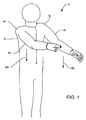
一方の腕又は両腕を広げて長時間仕事をしている人は、疲労を覚える。図1に示すように、ユーザUの広げた腕5にかかる重力W1とW2に、ユーザの肩Sr及びSl、及び背中Bの筋肉が抵抗する。長期にわたると、これが疲労となり、対応してパフォーマンスと精度が落ちる。例えば、外科医は、部分的にあるいは完全に伸ばした腕を、長時間にわたって動かし保持する必要がある。疲労、震え、及び精度の低下を伴う問題が多く報告されている。場合によっては、外科医は毎日の手順を実行できず、代わりに、手術と手術の間に一日の休息を取らなければならない。アームチェアに一般にみられるアームレストといった静止アームレストは、腕のサポートを提供するが、限られた範囲の位置でのみ有効である。従って、ユーザの腕をより大きな動作範囲にわたってサポートするアームサポートシステムが望まれている。 People who extend their arms or arms and work for a long time experience fatigue. As shown in FIG. 1, the muscles of the user's shoulders Sr and Sl and the back B resist the gravity W1 and W2 applied to the user U's extended arm 5. Over time, this becomes fatigue and the corresponding decrease in performance and accuracy. For example, a surgeon may need to move and hold a partially or fully extended arm for an extended period of time. Many problems with fatigue, tremors, and reduced accuracy have been reported. In some cases, the surgeon can not perform daily procedures, and instead must take a day's rest between surgery. A stationary armrest, such as the armrest commonly found in armchairs, provides support for the arm but is effective only in a limited range of positions. Therefore, an arm support system that supports the user's arm over a larger range of motion is desired.
この要求に取り組むために、本出願は、ユーザの一方の腕又は両腕を、例えばほぼ垂直にサポートする一方で、例えば、多方向及び多高さにわたって腕をほぼ自由に動かせるようにして、ユーザが広げた腕で長時間にわたって一またはそれ以上の仕事を行えるようにした様々な適応型アームサポートシステムを提供する。 In order to address this requirement, the present application supports the user by supporting one or both arms of the user, for example, substantially vertically, while allowing the arms to move, for example, substantially freely over multiple directions and heights. Provide a variety of adaptive arm support systems that allow one or more tasks to be performed for extended periods of time with the arms extended.
本明細書で使用されているように、「縦」は、ほぼ垂直、すなわち、ユーザUの脊柱にほぼ平行に延びる縦軸に沿っていることを意味する。従って、ユーザUは、一般的には動作を行う間に適応型アームサポートシステムを身に着けてほぼ直立しているが、ユーザUは、真の垂直方向から外れて縦軸を傾斜させるように移動することがある。本明細書で使用しているように、「横」は、ほぼ水平、すなわち、ユーザUの脊柱にほぼ平行に延びる縦軸に、ほぼ直交する、直交方向に延びる水平軸に沿っていることを意味する。例えば、水平軸は、ユーザUの肩の間に延在する軸にほぼ平行に延びている。 As used herein, "longitudinal" means approximately vertical, ie, along a longitudinal axis extending generally parallel to the spine of the user U. Thus, while user U generally wears the adaptive arm support system while performing an operation and is generally upright, user U is inclined so that the longitudinal axis deviates from the true vertical direction. May move. As used herein, “lateral” is to be substantially horizontal, ie, along an orthogonally extending horizontal axis substantially orthogonal to a longitudinal axis extending substantially parallel to the user U's spine means. For example, the horizontal axis extends generally parallel to the axis extending between the shoulders of the user U.
図2を参照すると、適応型アームサポートシステム10の第1の例示的実施例が示されている。ショルダーブラケット18がクロスバー20に連結されており、クロスバーは垂直バー15に連結している。垂直バー15は、さらに、ベルト連結板26でベルト25に連結されている。垂直バー15は、硬質、半硬質、あるいはフレキシブルであってもよく、矩形、正方形、円形、楕円形あるいはその他の形状又はこれらの組み合わせであるクロス部分を有しており、ベルト連結プレート26(図示せず)に対して回動するか、あるいはフレックスである。例えば、垂直バー15は、ユーザUがかがむまたは動くのに十分にフレキシブルである、又は可鍛性がある一方で、クロスバー20とベルト25との間に十分なコラム強度及び/又はその他のサポートを提供している。ショルダーブラケット18、クロスバー20、垂直バー15、及びベルト25は互いに、例えば、ハーネスなど、ユーザUの胴体に連結できる構造体を形成し、ハーネスによって担持されたあるいはハーネスに連結された部品用に、ユーザUの背骨に整列したほぼ垂直な軸16を規定している。ベルト25は、硬質、半硬質、一平面において硬質、所定領域において硬質、あるいはフレキシブルであってもよい。ベルトクロージャ28が設けられており、ベルト25を締めることができる。ベルト25は、ユーザのウエスト、腰、あるいはユーザの胴体のその他の領域の周りに固定することができ、垂直バー15(及び垂直軸16)がユーザの背骨にほぼ整列し、クロスバー20がユーザの肩近傍の領域にほぼ水平に装着される。ストラップ、ベルト、あるいはその他の締結デバイス(図示せず)を、例えば、米国特許出願番号13/353,268号に記載されているように、本明細書に述べた部品に加えて、あるいはこれに代えて設けて、適応型アームサポート10をユーザUに更に、固定することができる。
Referring to FIG. 2, a first exemplary embodiment of the adaptive
図に示すように、クロスバー20は、一またはそれ以上の補償エレメント50の取り付けポイントを有する装着ブロック22用の装着ポイントを提供している。従って、補償エレメント50は、アームブラケット30に取り付けられる。アームレスト36はアームブラケット30に取り付けられ、例えば、ユーザの腕の補償エレメント50へのサポート及び/又は連結を強化している。これらのエレメントは、ハーネス、ジャケット、シャツ、あるいはその他の衣類と一体的に形成して、その他の衣服の外、下、あるいはその衣服の代わりに身につけることができる。
As shown, the
図3Aを参照すると、近位端Pと遠位端Dを有する例示的補償エレメント50が示されている。図に示すように、金属、ポリマ、コンポジット、及び/又はその他の材料でできた(および、例えば、織った、セグメントした、単一ロッド又はロッド束、その他として形成した、中実、筒状、あるいはその他の中空部材として形成された)細長弾性部材52が、補償エレメント50の近位端Pにおける装着ピボット54に一方の端部が取り付けられている。例示的実施例では、弾性部材52は、超弾性ニチノールについての特性といった、超弾性特性を有している。弾性部材52は、ほぼ直線状であるか、あるいは、例えば外部源から自由に所定の構成にバイアスされるなど、緩んだ状態では曲がっている。装着ピボット54は、弾性部材52を取り囲んでいる、あるいはこれに連結されており、選択的に、例えば、回転経路57で示すように、回転軸56を中心に弾性部材52に対して回転する。以下に述べるように、位置決めの目的でストップカラー58が装着ピボット54に設けられている。弾性部材にしっかり取り付けたカラー59と60の配置で、弾性部材52に沿って装着ピボット54の位置を維持することができる。
Referring to FIG. 3A, an exemplary compensating
弾性部材52は、他端においてスライドロッド64にしっかり取り付けられている。スライドロッド64の遠位端は、補償エレメント50の遠位端Dを規定している。スライドロッド64は、スライドマウント68によって取り囲まれているか、またはスライドマウント68に連結されており、スライドマウント68に対してスライド経路70に沿って軸方向に移動し、及び/又は、回転経路72に沿ってスライドマウント68に対して回転する。選択的に、スライドロッド64は、スライドマウント68に対して固定されていてもよく、あるいは軸方向にスライドマウント68に対して固定されたままで、スライドマウント68に対して回転するようにフリーであってもよい。図に示すように、スライドロッド64は、一又は二のリミットストップ66を具え、スライドロッド64がスライドマウント68から外に出ないようにしている。スライドマウント68は、スライドマウントピボット74を具え、このピボットにおいてスライドマウントアンカ80に取り付けられており、ピボット軸76を規定している。スライドマウント68は、ピボット経路78に沿って、ピボット軸76を中心にしてスライドマウントアンカ80に対して回動できる。スライドマウントアンカ80も、ピボット軸84を規定するアンカピボット82を具えており、この軸を中心にスライドマウントアンカ80(及びスライドマウント68が)ピボット経路86に沿って回動する。図3Bは、補償エレメント50の分解図である。スライドマウントアンカ80内のスライドマウントピボット74は、スライドマウントアンカ80内のアンカスライドピボット75と回転可能に連結を形成している。
The
図3Cは、負荷Flに応じて回転軸56から、ほぼ偏向経路94に沿ってずらせて配置した補償エレメント50を示す。弾性部材52は、負荷Flに応じて曲げられた状態が示されており、この偏向に応じて、負荷Flに反対に働く復元力Frが生じる。弾性部材52の特性を変えて、例えば、弾性部材52の製造に使用する材料の剛性を変えることによって、及び/又は、弾性部材52の径及び/又は長さを大きくしたり小さくしたりすることによって、復元力Frを増減させることができる。弾性部材52の材料特性を選択して、大きな偏向レンジにより合致した復元力Frを提供することができる。例えば、一般的な歪パラメータで使用するニチノールワイヤは、復元力Frとより一致する。代替的に、弾性部材52の特性は、所望の偏向レンジ間で徐々に大きくなる復元力、又は可変復元力Frを提供するように選択してもよい。近位端Pにおける反作用モーメントMと反力Fraは、負荷Flに対向し、実質的な静止バランスを維持するように作用する。図に示すように、スライドロッド64は、一般的に、弾性部材52より固く、このような動きの間にほぼ直線を維持することができる。
FIG. 3C shows the compensating
図4A乃至4Cを参照すると、ユーザUに装着した又はユーザUに取り付けた適応型アームサポート10が示されている。図4Aは、後方から見た半斜視図であり、適応型アームサポート10に挿入したユーザUの右腕Arが示されている。アームレスト36は、アームArの下側に位置している。アームブラケット30は、アームレスト36に取り付けられており、アームレスト36を一またはそれ以上の補償エレメント50の遠位端Dに連結している(以下により詳細に説明する)。図4Aは、例示の形で、ユーザUの右腕Arの上で使用する4つの補償エレメント50を示している。補償エレメント50の弾性部材52は、図3Cに示すように、ユーザのアームの重量によって変位している。補償エレメント50の近位端Pは、装着ブロック22に連結しており、これはクロスバー20に取り付けられている。変位した補償エレメント50によって生じる復元力又は持ち上げ力Fr(図3Cに規定されている)は、ユーザUの右腕Arの重量Wrに応じて、重量Wr全て又は一部を持ち上げるあるいはカウンタバランスとして作用し、ユーザUが腕Arを延ばして維持するのに必要な筋力を小さくする。図4Bは、ユーザUの前からみた半斜視図であり、経路102にほぼ沿って下降したユーザUの左腕Al(この場合、二つの補償エレメント50によってのみサポートされている)を示し、ユーザの両腕の動きに反応する適応型アームサポート10の能力を示している。この場合、弾性部材52は、図4Aに示すよりさらに変位している。同様に、図4Cは、経路104にほぼ沿って上に持ち上げてユーザUの左腕Alを示しており、この場合、弾性エレメント52が図4Aに示すより少なく変位している。従って、適応型アームサポート10は、ユーザUの腕を無限の位置で収容することができ、ユーザUは、その腕を所望の位置に移動できる一方で、適応型アームサポート10はユーザUの腕と共に動く(又は適応する)と同時に、この動きを実質的に妨げることなく腕をサポートできる。
Referring to FIGS. 4A-4C, an
図4A乃至4Cに示すように、補償エレメントの数は、所望するとおり変えることができる。これによって、ユーザUがユーザの腕の重さ又は仕事の要求に応じて補償力の量を調整することができる。より多くの力が必要な場合、例えば、ユーザUの腕が重いあるいはユーザUが重い物体を持つことが期待されているような場合、より多くの補償エレメント50を加えることができ、逆に、より少ない力が必要な場合は、補償エレメント50を取ることができる。例えば、ユーザUが、ユーザの腕にかかる重量WrとWlの約40%(下方補償)を補償する軽いカウンターバランス力が必要な場合である。別の例では、ユーザUは、ユーザの腕に係る重量WrとWlの約115%(上方補償)を補償する重いカウンターバランス力を必要とする。
As shown in FIGS. 4A-4C, the number of compensating elements can be varied as desired. This allows the user U to adjust the amount of compensation in accordance with the weight of the user's arm or the demand for work. If more power is needed, for example if the user U's arms are heavy or the user U is expected to have a heavy object,
本明細書に述べているように、個々の補償エレメント50によって提供される持ち上げ力又は反力は変わるが、一般的に、一の最小補償エレメント50を用いることが考えらえる。
As mentioned herein, although the lifting force or reaction force provided by the
図5は、図4A乃至4Cに示す適応型アームサポートのような、適応型アームサポート10の上のユーザの腹部からの反力の例を示している。ショルダーブラケット18とベルト25は、ユーザUの胴体とその腹部又は腹部周囲に接触しており、ユーザの腕ArとAlによる適応的アームサポートシステム10へ入力した力及び/又はトルクに抵抗する面をユーザの身体のその他の部分に提供している。従って、ユーザの背中、肩、及び/又は腕自体の筋肉というよりはむしろ、身体のその他の部分が、適応的アームサポート10を介して伝達されたユーザの腕の負荷を実質的に支えている。例えば、これらの負荷を支えている腹部の領域は、筋肉の活動がこの負荷を支えることを要求しないことが好ましい。例えば、反力Frsbは、ユーザの背中又は肩の一部からの力によって適応的アームサポート10にかかる。Frst及びFrsfは、ユーザの肩の上及び前側によって与えられる。同様に、Frw及びFrhは、ユーザのウエストと腰のそれぞれの接触によって生じる。これらの実質的に静的な反力は、維持するのにわずかな仕事を要するのみであり、従って、ユーザUの疲労に有意に寄与しない。
FIG. 5 shows an example of the reaction force from the abdomen of the user on the
図6Aは、例えば、図4Aに示すものと同様に、補償エレメント50の近位端Pのハーネスへの取り付け部の詳細を示す図である。図に示すように、各補償エレメント50の装着ピボット54が、装着ブロック22の溝(図示せず)の中に据え付けられている。ストップカラー58が、装着ブロック22に対して装着ピボット54を配置している。弾性部材52は、装着ピボット54内で、回転軸56を中心に回転可能である(回転経路57で示す)。このように、補償エレメント50は、仕事を実行しているユーザUの腕の動きに応じて、軸56を中心に回転可能である。装着ブロック22は、必要に応じて一またはそれ以上の補償エレメント50を収容できる。装着ブロック22は、図6Aに示す直線パターンと異なる装着ブロックの配置を提供している。例えば、正方形、又は円形である。
FIG. 6A shows a detail of the attachment of the proximal end P of the
選択的に、装着ブロック22は、解放可能なコネクタ(図示せず)を用いて、ユーザUが所望するように、例えば、経路108に沿ったクロスバー20に沿って再配置して、ユーザの肩幅を収容することができる。これに加えて、あるいは代替的に、クロスバー22は、例えば経路110に沿って垂直バー15に対して調整可能として、ユーザUの腹部長を収容することができる。このように、適応的アームサポート10のハーネスは、ユーザUのサイズ及び/又は寸法を収容するよう調整可能である。
Optionally, the mounting
図6Bは、例えば、図4Aに示すものと同様に、補償エレメント50の遠位端Dのアームブラケット30への取り付けの詳細を示す図である。弾性部材52は、図3Aに示すように、スライドロッド64にしっかり取り付けられている。スライドロッド64は、スライドマウント68に対して、ほぼスライド経路70に沿って移動可能である、及び/又は、回転経路72に沿ってスライドマウント68に対して回転可能であり、例えば、アームブラケット30の位置がユーザの腕Arの動きから生じている場合に、動きを収容する。スライドマウント68は、ピボット軸76を中心に、及び/又は、ピボット経路78に沿って、スライドマウントアンカ80に対して回転する。
FIG. 6B shows details of the attachment of the distal end D of the
スライドマウントアンカ80は、アンカピボット82を具えており、これがスライドマウントアンカ80(したがって、スライドマウント68も)がその周りをピボット経路86に沿って回動できるピボット軸84を規定する。スライドマウントアンカ80は、回転可能な接続部115を介して、例えば、リベット又はその他の回転可能な締結具(図示せず)を用いて、アンカピボット82でアームブラケット30に取り付けられており、スライドマウントアンカ80(したがって、補償エレメント50の遠位端Dも)が、ほぼピボット経路86に沿って回動できるようにしている。回転可能な接続部115を通って作用する復元力Fr(図3Cを参照して上述)は、アームブラケット30及び/又はアームレスト36を介してアームArにかかり、従って、重力Wr全て又はその一部に対抗している。このように、補償エレメント50(及び、一般に適応型アームサポートシステム10)は、カウンタバランス力を提供しつつ、例えば、実質的にその動きを妨げることなく、腕を同時にサポートするといった、ユーザUの腕の動きに「適応」するようにユーザの腕のあらゆる動き及び無限の位置を受けている。
The
後方から見た半斜視図である図7Aは、位置調整特性を持つ適応型アームサポートシステム200の別の例示的実施例を示す。クロスバー20は、クロスバーハブ210に取り付けられている。クロスバー回転ハウジング215内に収容されており、ほぼ円形断面をもつクロスバーハブ210は、経路219にほぼ沿って、回転軸217を中心にクロスバー回転ハウジング215に対して回転可能である。装着ブロック22は、一またはそれ以上の装着ピボット54(補償エレメント50の近位端Pで)が配置されており、クロスバー20に取り付けられているため、(例えば、以下に述べるように)軸219を中心にクロスバー20と共に回転できる。
FIG. 7A, which is a semi-perspective view from the rear, shows another exemplary embodiment of an adaptive
図7Aは、クロスバー20の環状位置を固定するための特徴を示している(例えば、クロスバー20は、クロスバー回転ハウジング215に対して回動している)。ロックバー222は、垂直バー15にしっかり取り付けられている。ロックバー222の端部へ取り付けられているのは、ロックプレート224であり、一またはそれ以上のロック特性226に対する装着を提供している。角度ロックハンドル232がブロックバー20に連結されており、一又はそれ以上のロック特性226に対して調整可能に配置されるように構成されており、これによって、クロスバー20の角度位置を固定している。角度ロックハンドル232は、硬質、フレキシブル、又は回動連結部(図示せず)によってクロスバーに取り付けられており、適宜のロック特性226近傍への角度ロックハンドル232の再位置決めを容易にしている。
FIG. 7A shows features for securing the annular position of the crossbar 20 (eg, the
図7Bは、適応型アームサポートシステム200の側面であり、腕Arの所望の下側位置に調整されている(例えば、ウエスト位置近傍での仕事用)。角度ロックハンドル232は、ロック機構226と共働して、装着ピボット54の軸56をほぼ垂直軸Vに対して前側へほぼ角度244だけ傾けた状態で示されている。ユーザの腕Arは、軸240に沿った方向をほぼ向いており、約角度242だけほぼ水平な軸Hから広がっている。この位置では、腕Arの重量は、100%補償されており、すなわちニュートラル位置にある。ユーザUは、どの方向にも腕Arを自由に動かすことができるが、軸240に沿って位置を維持するために必要とされる筋肉運動は、ほんのわずかであるか不要である。
FIG. 7B is a side view of the adaptive
図7Cは、適応型アームサポートシステム200の側面図であり、腕Arの好ましい上側位置に調整されている(例えば、頭上での仕事用)。角度ロックハンドル232が示されており、ロック特性226と共働してほぼ垂直軸Vに対して、ほぼ角度250だけ後ろ側に、装着ピボット54の軸56を傾けている。ユーザの腕Arは、ほぼ軸246に沿う方向を向いており、ほぼ水平方向の軸Hからほぼ角度248だけ広がっている。この位置では、腕Arの重量は100%補償されており、すなわち、ニュートラル位置にある。ユーザUは、腕Arをあらゆる方向に自在に動かすことができるが、軸246に沿って位置を維持するために必要とされる筋肉運動は、ほんのわずかであるか不要である。すなわち、適応型アームサポートシステム200は、例えば、下側ニュートラル位置と上側ニュートラル位置との間の複数位置において、所望のニュートラル位置に調整することができる。
FIG. 7C is a side view of the adaptive
図8Aは、補償エレメント350の別の実施例を示す図であり、この例は近位端Pに装着ピボットがない点で上述の補償エレメントと異なる。弾性部材52は、スライドロッド64の一端にしっかり取り付けられている。スライドロッド64の他端は、遠位端Dを規定している。スライドロッド64は、スライドマウント68で囲まれており、スライド経路70に沿ってスライドマウント68に対して移動できる、及び/又は、回転経路72に沿ってスライドマウント68に対して回転できる。スライドロッド64は、二つのリミットストップ66を具えており、スライドロッド64がスライドマウント68から確実にでないようにしている。スライドマウント68は、スライドマウントピボット74も具えており、ここにスライドマウントアンカ80に取り付けられて、ピボット軸76を規定している。スライドマウント68は、ピボット軸76を中心にスライドマウントアンカ80に対して、及び/又は、ピボット経路78に沿って回動できる。スライドマウントアンカ80は、ピボット軸84を規定するアンカピボット82を具え、この軸を中心にスライドマウントアンカ80(したがって、スライドマウント68も)が、ピボット経路86に沿って回動できる。
FIG. 8A shows another embodiment of the compensating
図8Bは、適応型アームサポートシステム300の例示的実施例を示す図であり、このシステムは補償エレメント350用の単一のピボットマウントを具える。補償エレメント350の近位端Pは、単一ピボットハブ310にしっかり取り付けられている。単一ピボットハブ310は、単一ピボットハウジング312に回転可能に装着されており、ピボット軸314を中心に、経路316にほぼ沿って自在に回動する。このように、一またはそれ以上の補償エレメント350が、ユーザの腕Arの動きに応答して単一軸314の周りを回動しつつ、腕Arの重量を補償する力を提供している。
FIG. 8B is a diagram illustrating an exemplary embodiment of an adaptive
図9A乃至9Cを参照すると、ユーザUが装着している適応型アームサポートシステム400の別の例示的実施例が示されている。システム400は、ここに記載したその他の実施例とほぼ同様であり、従って、フレーム又はハーネスのクロスバー20と、ユーザUの片方又は両方の腕を支えるアームブラケット30、及び/又は、アームレスト36の間に連結された一またはそれ以上の補償エレメント(各アームにつき一つが示されている)50を具える。上述の実施例とは異なり、補償エレメント50の近位端が、例えば、アンカポイント425などにおけるヒンジ部材410、420に連結されてピボットポイント415を形成している。例えば、第1のヒンジ部材410は、クロスバー20に固定的に取り付けることができ、補償エレメント50のアンカポイント425は、第2のヒンジ部材420内に固定的に受けられている、あるいはこれに取り付けられている。ヒンジ部材410、420は、図に示すように単軸430を中心に互いに回動でき、あるいは、複数軸を中心に回動できる又は、二つの寸法(図示せず)で回動できる回転ソケットを具えている。従って、ヒンジ部材410、420によって、アンカポイント425は、ユーザの腕の経路432及び434にほぼ沿った横方向の動きに応じて、軸430を中心に経路435及び436にほぼ沿って回動する。
Referring to FIGS. 9A-9C, another exemplary embodiment of an adaptive
図10A乃至10Eを参照すると、ユーザUに装着されている適応型アームサポートシステム500の別の例示的実施例が示されている。システム500は、ここに記載したその他の実施例とほぼ同様であり、従って、フレーム又はハーネスのクロスバー20とユーザUの一方の腕又は両腕を支えているアームブラケット30及び/又はアームレスト36との間に連結された一又はそれ以上の補償エレメント(各腕につき一つが示されている)50を具える。図9A乃至9Cのシステム400と同様に、補償エレメント50の近位端は、ヒンジ部材510、520に連結されてピボットポイント512を形成しており、例えば、縦軸550を中心にした及び/又は経路552に沿ったユーザUの腕の動きを受けることができる。例えば、第1のヒンジ部材510は、クロスバー20に固定的に取り付けられており、第2のヒンジ部材520は、縦軸545を中心に、例えば、経路560及び565にほぼ沿ってユーザの腕の横方向の動きに応じて、第1のヒンジ部材510に対して自由に回動することができる。
Referring to FIGS. 10A-10E, another exemplary embodiment of an adaptive
上述の実施例と異なり、ロック可能に回転するマウント530が第2のヒンジ部材520に、遠位ピボットポイント522で連結されており、回転可能なマウント530は軸570を中心に選択的に回転できる。補償エレメント50の近位端は、回転可能なマウント530に連結されて、例えば、ここに記載したその他の実施例と同様に、回転可能なマウント530内のソケット540に永久的にあるいは取り外し可能に受けられている。使用中に、回転可能なマウント530を開放することができ、軸570を中心とする第2のヒンジ部材520に対する回転可能なマウント530の相対的方向を調整することができ、従って、回転可能なマウント530を再度ロックして、相対的な方向を固定することができる。
Unlike the embodiment described above, the lockable
このように、補償エレメント50の近位端は、例えば、経路560及び565にほぼ沿ったユーザの腕の横方向の動きに応じて、縦軸545を中心に自由に回動することができる一方で、回転可能なマウント530は選択的に調製してロックすることができる。この構成では、ヒンジ部材510、520の縦軸545は、例えば、縦バー15の縦軸にほぼ平行といった、ハーネスの縦軸に対してほぼ平行を維持することができる。これは、縦軸430がハーネスの縦軸に常に並行ではない点で、図9A乃至9Cのシステム400と異なる。
Thus, while the proximal end of the compensating
遠位ピボット522を使用して、軸570の周りのヒンジ部材510、520に対して回転可能なマウント530をロック可能に回動させることができ、これはユーザUの腕にかかる復元力を変更して、例えば、システム500に関する補償レベル及び/又は「ゼロ」点を調整する。例えば、図10B及び10Cに示すように、回転可能なマウント530が、第2のヒンジ部材520を伴い正方形である。図10Dでは、回転可能なマウント530は、第2のヒンジ部材520から、例えば、経路580にほぼ沿って回転可能にオフセットしており、これがユーザUの腕が下がったときに、ゼロポイントを上げるか、あるいは補償を大きくする。なぜなら、補償エレメント50の近位端が、ハーネスの縦軸からオフセットしているからである。同様に、図10Eでは、回転可能なマウント530が第2のヒンジ部材520から、例えば、経路582に沿って回転可能にオフセットしており、これによって、ユーザの腕が下がったときに、ゼロポイントを下げるあるいは補償を下げることができる。
The
上述したシステムを、様々な分野及びアプリケーションに使用できることは自明である。例えば、このシステムは、例えば、外科医、歯科医、などの医師が身に着けて、長時間にわたる手術、医療、あるいは歯科の処置において医師の腕のエクステンションを容易にすることができる。このシステムは、例えば、塗装工、大工、などの建設作業員、たとえば、製造組立などにかかわる製造作業員、身体障害者、及び/又は、一方の腕又は両腕をユーザの身体から外側に向けて広げて長時間にわたって仕事を行うその他のユーザが身に着けることができる。 It is self-evident that the system described above can be used in various fields and applications. For example, the system can be worn by a physician, eg, a surgeon, dentist, etc., to facilitate extension of the physician's arm in long-term surgery, medical, or dental procedures. This system, for example, directs a construction worker such as a painter, carpenter, etc., for example, a manufacturing worker involved in manufacturing assembly, etc., a disabled person, and / or one arm or arms outward from the user's body It can be worn by other users who are working out for extended periods of time.
一般的に、ここに記載した装置及びシステムは、例えば、ウエスト、腰回り、肩、背中、胸、などのユーザの腹部にハーネスを固定することによって、ユーザの身体に装着する又は配置することができる。例えば、ハーネスに連結した又はハーネスが担持しているこの装置またはシステムのアームサポートを使用して、ユーザの腕をサポートして、アームサポートがユーザの腕の動きをほぼ追従することができる。ユーザは、従って、ユーザの腕の動きを伴う一またはそれ以上の仕事を行い、アームサポートは、その動きを実質的に妨げることなく、ユーザの腕に係る重力を少なくとも部分的にオフセットする、及び/又は、ユーザの腹部へ重力を少なくとも部分的に移動させることができる。このように、ここに開示した装置及びシステムは、より長時間にわたり、及び/又は、疲労及び/又はけがを少なくして、ユーザが仕事を行うのを容易にすることができる。 In general, the devices and systems described herein may be worn or placed on the user's body, for example, by securing the harness to the user's abdomen, such as the waist, waist, shoulders, back, chest, etc. it can. For example, using the arm support of this device or system coupled to the harness or carried by the harness, the arm support can substantially follow the movement of the user's arm, supporting the user's arm. The user thus performs one or more tasks involving the movement of the user's arm, and the arm support at least partially offsets the gravity associated with the user's arm, without substantially preventing its movement, and And / or gravity can be at least partially moved to the user's abdomen. In this manner, the devices and systems disclosed herein can facilitate the user to perform work for longer periods of time and / or less fatigue and / or injury.
ここに記載した実施例で示す要素又は部材は、単に特定の実施例についての例示に過ぎず、ここに開示したその他の実施例に使用しても、あるいはこれと組み合わせて使用してもよいことは明らかである。 The elements or components shown in the embodiments described herein are merely illustrative of the particular embodiments and may be used in or in combination with the other embodiments disclosed herein. Is clear.
本発明は様々な変更、変形が可能であるが、その特定の例は図面に示されており、ここに詳細に述べられている。しかし、本発明は、これらの開示した特定の形又は方法に限定されるものではなく、特許請求の範囲に記載の範囲内の全ての変更例、均等物、変形例をカバーするものである。
While the invention is susceptible to various modifications and alternative forms, specific examples thereof have been shown in the drawings and are herein described in detail. The present invention, however, is not limited to these specific forms or methods disclosed, but covers all modifications, equivalents, and variations within the scope of the claims.
Claims (17)
ハーネスであって、ユーザの胴回りに装着できるように構成したアタッチメントバンドと、当該アタッチメントバンドから延在してユーザの背中に沿って延在するように構成され、且つ前記ハーネスを装着しているユーザの背骨とほぼ平行に延在する垂直軸を規定する胴体ブラケットと、前記ユーザの背中側でユーザの両肩の間に少なくとも部分的に延在するように構成したクロスバーとを具えるハーネスと;
ユーザの腕をサポートするように構成したアームサポートであって、ユーザの動きを実質的に妨げることなく当該動きを追従しながら、前記腕の動きに適応するように構成したアームサポートと;
前記ハーネスと前記アームサポートとの間に連結して、ユーザが動いて、前記アームサポートが当該ユーザの腕の動きを追従するときに前記腕にかかる重力を少なくとも部分的にオフセットする一またはそれ以上の補償エレメントと;
を具え、
前記一またはそれ以上の補償エレメントの各々が、前記クロスバーに連結された第1の端部と前記アームサポートに連結された第2の端部を有する細長弾性部材を具え、当該細長弾性部材が、前記クロスバー及び前記アームサポートの間で一方の肩の上を通るように構成され、且つ所定の形状に、前記ユーザが動いたときに当該ユーザの腕に働く重力を少なくとも部分的にオフセットするように弾性的に偏向可能にバイアスされている;
ことを特徴とするシステム。 In a system that supports the user's arm:
A harness, a user and an attachment band configured to be attached to the waist of the user, is configured to extend along the back of the user to extend from the attachment band is and wearing the harness A harness including a torso bracket defining a vertical axis extending substantially parallel to the spine of the patient; and a cross bar configured to extend at least partially between the user's shoulders on the back side of the user ;
An arm support configured to support a user's arm, wherein the arm support is configured to adapt to the movement of the arm while following the movement without substantially interfering with the user's movement;
One or more couplings between the harness and the arm support for at least partially offset gravity applied to the arm as the user moves and the arm support follows the movement of the user's arm And compensation elements;
Equipped
Each of the one or more compensating elements comprises an elongated resilient member having a first end coupled to the cross bar and a second end coupled to the arm support, the elongated resilient member comprising Configured to pass over one of the shoulders between the cross bar and the arm support, and at least partially offset the gravity acting on the user's arm when the user moves in a predetermined shape So as to be elastically biased biased;
A system characterized by
ハーネスであって、ユーザの胴回りに装着できるように構成したアタッチメントバンドと、前記アタッチメントバンドから延在してユーザの背中に沿って延在するように構成され、且つ前記ハーネスを装着しているユーザの背骨とほぼ平行に延在する垂直軸を規定する胴体ブラケットと、前記ユーザの背中側でユーザの両肩の間に少なくとも部分的に延在するように構成したクロスバーとを具えるハーネスと;
ユーザの腕の一部をサポートするように構成したアームサポートと;
前記ハーネスと前記アームサポートとの間に連結して、ユーザの腕が前記アームサポートにサポートされつつ、ユーザの動きを実質的に妨げることなくユーザが動くときに、前記ユーザの腕にかかる重力を少なくとも部分的にオフセットする一またはそれ以上の補償エレメントと;
を具え、
前記一またはそれ以上の補償エレメントの各々が、前記クロスバーの一方の端部に連結された第1の端部と前記アームサポートに連結された第2の端部とを有する細長弾性部材を具え、当該細長弾性部材が、前記クロスバー及び前記アームサポートの間で一方の肩の上を通るように構成され、且つ所定の形状に、前記ユーザが動いたときに当該ユーザの腕に働く重力を少なくとも部分的にオフセットするように弾性的に偏向可能にバイアスされている;
ことを特徴とするシステム。 In a system that supports the user's arm:
A harness, the attachment band configured to be attached to the waist of the user, is configured to extend along the back of the user and extends from the attachment band is and wearing the harness user A harness including a torso bracket defining a vertical axis extending substantially parallel to the spine of the patient; and a cross bar configured to extend at least partially between the user's shoulders on the back side of the user ;
With arm support configured to support part of the user's arm;
Coupled between the harness and the arm support, the gravity applied to the user's arm when the user moves while the user's arm is supported by the arm support without substantially interrupting the user's movement One or more compensating elements that are at least partially offset;
Equipped
Each of the one or more compensating elements comprises an elongated resilient member having a first end coupled to one end of the crossbar and a second end coupled to the arm support. The elongated elastic member is configured to pass on one shoulder between the cross bar and the arm support, and in a predetermined shape, the gravity acting on the user's arm when the user moves Resiliently biased to be at least partially offset;
A system characterized by
ハーネスであって、ユーザの胴回りに装着するように構成したアタッチメントバンドと、当該アタッチメントバンドから延在してユーザの背中に沿って延在するように構成され、且つ前記ユーザの背中の後ろに前記ハーネスを装着しているユーザの背骨とほぼ平行に延在する垂直軸を規定する胴体ブラケットと、前記ユーザの背中側でユーザの両肩の間に少なくとも部分的に延在するように構成したクロスバーと、を具えるハーネスと;
ユーザの上腕の下側を受けるように成形されたアームレストと、当該アームレストに取り付けられたアームブラケットとを具えるアームサポートであって、前記アームレストが前記ユーザの腕の動きを実質的に妨げることなく当該動きを追従しながら、前記腕の動きに適応するように構成されている、アームサポートと;
前記ユーザの一方の肩の後部で前記クロスバーの端部に連結された第1の端部と、前記アームブラケットに連結された第2の端部を有する細長弾性部材を具える一またはそれ以上の補償エレメントであって、前記細長弾性部材が、前記クロスバー及び前記アームサポートの間で一方の肩の上を通るように構成され、且つ前記第1の端部と第2の端部の間の軸を規定する所定の方向にバイアスされており、前記第2の端部が前記第1の端部に対して、前記軸から離れて湾曲した方向に曲げることができ、前記所定の方向に向けて少なくとも部分的にまっすぐにバイアスされており、これによって、前記ユーザが動いて前記アームレストがユーザの腕の動きに追従した時に、前記腕に働く重力を少なくとも部分的にオフセットするように前記アームレストに曲げ復元力を与えることを特徴とするシステム。 In a system that supports the user's arm:
A harness, the attachment band configured to be worn on the waist of the user, is configured to extend along the back of the user to extend from the attachment band, and the behind the back of the user A fuselage bracket defining a vertical axis extending substantially parallel to the spine of the user wearing the harness, and a cross configured to extend at least partially between the user's shoulders on the back side of the user A bar and a harness comprising
An arm support comprising an armrest shaped to receive a lower side of a user's upper arm, and an arm bracket attached to the armrest, wherein the armrest does not substantially impede movement of the user's arm An arm support configured to adapt to the movement of the arm while following the movement;
One or more elongated elastic members having a first end connected to the end of the cross bar at the rear of one of the shoulders of the user and a second end connected to the arm bracket Compensation element, wherein the elongated resilient member is configured to pass over one shoulder between the cross bar and the arm support, and between the first end and the second end And the second end can be bent in a direction curved away from the axis relative to the first end, the second end being bent in the predetermined direction. The arm is at least partially straight biased, so as to at least partially offset the gravity acting on the arm when the user moves and the armrest follows the movement of the user's arm. System characterized by providing a restoring force bending the rest.
ハーネスであって、ユーザの胴回り装着できるように構成したアタッチメントバンドと、当該アタッチメントバンドから延在してユーザの背中に沿って延在するように構成され、且つ前記ハーネスを装着するユーザの背骨とほぼ平行に延在する垂直軸を規定する胴体ブラケットと、前記ユーザの背中側でユーザの両肩の間に少なくとも部分的に延在するように構成したクロスバーとを具えるハーネスと;
ユーザの腕をサポートするように構成したアームサポートと;
前記ハーネスと前記アームサポートとの間に連結可能であり、ユーザが動き、前記アームサポートが当該ユーザの腕の動きを追従するときに前記腕にかかる重力を少なくとも部分的にオフセットする複数の補償エレメントであって、各補償エレメントが、前記クロスバーに連結した第1の端部及び前記アームサポートと連結した第2の端部を有する細長弾性部材を具える、補償エレメントと;
を具え、
前記細長弾性部材が、前記クロスバー及び前記アームサポートの間で一方の肩の上を通るるように構成され、且つ所定の形状に、前記ユーザが動いたときに当該ユーザの腕に働く重力を少なくとも部分的にオフセットするように弾性的に偏向可能にバイアスされていることを特徴とするシステム。 In a system that supports the user's arm:
A harness, the attachment band configured to allow the waist worn by the user, is configured to extend along the back of the user to extend from the attachment band, the user of the spine and mounting the harness A harness comprising a torso bracket defining a generally parallel extending vertical axis; and a cross bar configured to extend at least partially between the user's shoulders on the back side of the user ;
Arm support configured to support the user's arm;
A plurality of compensation elements connectable between the harness and the arm support, the user moving and at least partially offset gravity applied to the arm as the arm support follows the movement of the user's arm Compensation elements, each compensation element comprising an elongated resilient member having a first end coupled to the cross bar and a second end coupled to the arm support;
Equipped
The elongated elastic member is configured to pass on one of the shoulders between the cross bar and the arm support, and has a predetermined shape that acts on the arm of the user when the user moves. A system characterized in that it is resiliently biased to be at least partially offset.
ユーザの胴体にハーネスを配置するステップであって、前記ハーネスが、前記ユーザの胴体に装着されたアタッチメントバンドと、当該アタッチメントバンドから延在してユーザの背中に沿って延在するように構成され、且つユーザの背骨とほぼ平行に延在する垂直軸を規定する胴体ブラケットと、前記ユーザの背中側でユーザの両肩の間に少なくとも部分的に延在するように構成したクロスバーとを具える、ステップと;
ユーザの腕の動きを追従するアームサポートと、当該アームサポートと前記ハーネスの間に連結された一またはそれ以上の補償エレメントを用いて、ユーザの腕の一部をサポートするステップであって、前記一またはそれ以上の補償エレメントの各々が、前記クロスバーに連結された第1の端部と前記アームサポートに連結された第2の端部を有する細長弾性部材を具え、当該細長弾性部材が、前記クロスバー及び前記アームサポートの間で一方の肩の上を通るものであり、所定の形状に、前記ユーザが動いたときに当該ユーザの腕に働く重力を少なくとも部分的にオフセットするように弾性的に偏向可能にバイアスされている、ステップと;
ユーザの腕の動き及び休みを含む一またはそれ以上の仕事を実行するステップであって、前記一またはそれ以上の補償エレメントが、前記動きを実質的に妨げることなく、当該動きの間前記ユーザの腕に係る重力を少なくとも部分的にオフセットするステップと;
を具えることを特徴とする方法。 In a way to support the user's arms while doing one or more tasks:
Disposing a harness trunk of the user, the harness, the attachment band is attached to the body of the user, it is configured to extend along the back of the user to extend from the attachment band And a torso bracket defining a vertical axis extending substantially parallel to the user's spine , and a cross bar configured to extend at least partially between the user's shoulders on the back side of the user Step, with
Supporting a portion of the user's arm with an arm support that follows the movement of the user's arm and one or more compensating elements connected between the arm support and the harness, Each of the one or more compensating elements comprises an elongated resilient member having a first end coupled to the cross bar and a second end coupled to the arm support, the elongated resilient member comprising: Passing over one shoulder between the cross bar and the arm support, resilient to at least partially offset the gravity acting on the user's arm when the user moves in a predetermined shape Are biased so as to be deflectable, steps;
Performing one or more tasks including movement and rest of the user's arm, wherein the one or more compensating elements do not substantially impede the movement, during the movement of the user At least partially offset the gravity associated with the arm;
A method comprising:
所望のサポート特性を有する一またはそれ以上の補償エレメントを選択するステップと;
前記一またはそれ以上の補償エレメントを前記ハーネスと前記アームサポートとの間に連結するステップと;
を具えることを特徴とする方法。 The method according to claim 15 further comprises:
Selecting one or more compensation elements having desired support characteristics;
Connecting the one or more compensating elements between the harness and the arm support;
A method comprising:
Applications Claiming Priority (3)
| Application Number | Priority Date | Filing Date | Title |
|---|---|---|---|
| US13/563,728 US9999534B2 (en) | 2012-07-31 | 2012-07-31 | Adaptive arm support systems and methods for use |
| US13/563,728 | 2012-07-31 | ||
| PCT/US2013/052782 WO2014022433A1 (en) | 2012-07-31 | 2013-07-30 | Adaptive arm support systems and methods for use |
Publications (3)
| Publication Number | Publication Date |
|---|---|
| JP2015524752A JP2015524752A (en) | 2015-08-27 |
| JP2015524752A5 JP2015524752A5 (en) | 2016-10-06 |
| JP6515265B2 true JP6515265B2 (en) | 2019-05-22 |
Family
ID=50023996
Family Applications (1)
| Application Number | Title | Priority Date | Filing Date |
|---|---|---|---|
| JP2015525523A Active JP6515265B2 (en) | 2012-07-31 | 2013-07-30 | Adaptive arm support system and method of using the same |
Country Status (5)
| Country | Link |
|---|---|
| US (2) | US9999534B2 (en) |
| EP (1) | EP2879843B1 (en) |
| JP (1) | JP6515265B2 (en) |
| CA (1) | CA2880561C (en) |
| WO (1) | WO2014022433A1 (en) |
Families Citing this family (24)
| Publication number | Priority date | Publication date | Assignee | Title |
|---|---|---|---|---|
| JP6086482B2 (en) * | 2013-04-05 | 2017-03-01 | 学校法人自治医科大学 | Joint contracture, stiffness or spasticity simulator |
| WO2015157473A1 (en) | 2014-04-08 | 2015-10-15 | Levitate Technologies, Inc. | Heavy capacity arm support systems |
| EP3209467B1 (en) * | 2014-10-24 | 2021-11-24 | Enhance Technologies, LLC | Arm support systems |
| US10569413B2 (en) * | 2015-12-22 | 2020-02-25 | Ekso Bionics, Inc. | Exoskeleton and method of providing an assistive torque to an arm of a wearer |
| US10058994B2 (en) * | 2015-12-22 | 2018-08-28 | Ekso Bionics, Inc. | Exoskeleton and method of providing an assistive torque to an arm of a wearer |
| SE541542C2 (en) * | 2016-10-05 | 2019-10-29 | Bioservo Tech Aktiebolag | Armlifting support device |
| PL3529015T3 (en) * | 2016-10-21 | 2021-11-22 | Skel-Ex Holding B.V. | Force-balancing support |
| DE102016121203A1 (en) * | 2016-11-07 | 2018-05-09 | Otto Bock Healthcare Gmbh | Device for supporting an arm |
| JP2018122394A (en) * | 2017-01-31 | 2018-08-09 | 株式会社マキタ | Work assisting tool |
| US10918559B2 (en) | 2017-04-25 | 2021-02-16 | Ossur Iceland Ehf | Interface system in an exoskeleton |
| EP3624996A4 (en) | 2017-05-15 | 2021-03-24 | Enhance Technologies, LLC | Arm support systems |
| WO2018218228A1 (en) * | 2017-05-25 | 2018-11-29 | U.S. Bionics, Inc. | Adjustable trunk and hip assembly for exoskeleton apparatus |
| DE102017112436B4 (en) * | 2017-06-06 | 2019-05-29 | Ottobock Se & Co. Kgaa | Device for supporting at least one arm of a user |
| US11000439B2 (en) | 2017-09-28 | 2021-05-11 | Ossur Iceland Ehf | Body interface |
| USD876654S1 (en) | 2018-04-24 | 2020-02-25 | Ossur Iceland Ehf | Posterior strut |
| DE102018119755A1 (en) | 2018-08-14 | 2020-02-20 | Ottobock Se & Co. Kgaa | Device for supporting at least one arm of a user |
| CN109732564A (en) * | 2018-11-23 | 2019-05-10 | 上海谐趣技术有限公司 | A kind of lumbar vertebrae weight bearing auxiliary ectoskeleton |
| KR102603041B1 (en) * | 2018-12-12 | 2023-11-16 | 현대자동차주식회사 | Wearable apparatus for assisting muscular strength |
| DE102019104344A1 (en) * | 2019-02-20 | 2020-08-20 | Pohlig Gmbh | Device for supporting at least one arm of a user and headrest |
| DE102019113684A1 (en) * | 2019-05-22 | 2020-11-26 | Ottobock Se & Co. Kgaa | Device for supporting at least one arm |
| TR201909434A2 (en) * | 2019-06-25 | 2021-01-21 | Goekhan Bursoy | Wearable Force Support System for Upper Limbs |
| PL239976B1 (en) * | 2020-02-19 | 2022-01-31 | Xdeep Spolka Z Ograniczona Odpowiedzialnoscia | Diving harness |
| RU202453U1 (en) * | 2020-06-11 | 2021-02-18 | Общество с ограниченной ответственностью "Экзомед" | Passive exoskeleton of the upper limbs |
| FR3124102B1 (en) * | 2021-06-18 | 2023-06-30 | Ergosante Tech | LIGHTWEIGHT EXOSKELETON |
Family Cites Families (36)
| Publication number | Priority date | Publication date | Assignee | Title |
|---|---|---|---|---|
| US3120332A (en) * | 1962-09-05 | 1964-02-04 | Theodore R White | Umbrella support |
| DE2615209A1 (en) | 1975-04-15 | 1976-10-28 | Teufel Wilh Jul Fa | UNIVERSAL ORTHESIS |
| US4298149A (en) | 1978-01-17 | 1981-11-03 | Panavision, Incorporated | Body harness for cinematographer |
| JPS54127735U (en) * | 1978-02-25 | 1979-09-05 | ||
| JPS58134913A (en) * | 1982-01-29 | 1983-08-11 | 山田機械工業株式会社 | Working aid tool |
| US5020521A (en) * | 1982-11-10 | 1991-06-04 | Salort Guy J | External apparatus for motor handicaps of at least one upper limb |
| US5111983A (en) | 1986-02-10 | 1992-05-12 | Simmons Elex M | Camera stabilizing device |
| JPS6373963A (en) * | 1987-07-31 | 1988-04-04 | ギ−、サロ−ル | Exterior jig for hand dyskinesia |
| JPH02113942U (en) * | 1989-02-28 | 1990-09-12 | ||
| JP2721438B2 (en) * | 1991-04-01 | 1998-03-04 | 裕章 金子 | Arm fatigue reduction device |
| US5360391A (en) * | 1993-04-26 | 1994-11-01 | Johnson Lanny L | Shoulder brace |
| JPH07107861A (en) * | 1993-10-13 | 1995-04-25 | Techno Mach:Kk | Shoulder carrying-type arm-supporting assistant tool |
| JP2889859B2 (en) | 1996-08-29 | 1999-05-10 | 保 柳沢 | Shoulder support device |
| US5829652A (en) * | 1997-02-19 | 1998-11-03 | Denzer; Joanne | Body-conformable apparatus |
| US6082034A (en) * | 1998-09-11 | 2000-07-04 | Musmanno; Brad A. | Apparatus for supporting the arm when extended from the body |
| KR100299210B1 (en) | 1999-03-12 | 2001-09-22 | 박호군 | Master device having force reflective function |
| US6709411B1 (en) * | 1999-03-18 | 2004-03-23 | David R. Olinger | Shoulder brace, and methods of use |
| US7918808B2 (en) | 2000-09-20 | 2011-04-05 | Simmons John C | Assistive clothing |
| JP2002153115A (en) | 2000-11-24 | 2002-05-28 | Haimuun Kk | Both arms supporting apparatus of human body attachment type for operation of high-altitude object |
| US6645093B2 (en) * | 2001-10-05 | 2003-11-11 | Mark C. Sheppard | Basketball shot trainer |
| DE102005001843B4 (en) * | 2005-01-14 | 2020-12-17 | Andreas Stihl Ag & Co. Kg | Carrying system for an implement and method for pruning trees |
| JP2007097636A (en) * | 2005-09-30 | 2007-04-19 | Matsushita Electric Ind Co Ltd | Muscular strength assisting apparatus |
| JP2008220883A (en) * | 2007-03-16 | 2008-09-25 | Shibaura Institute Of Technology | Work support apparatus |
| JP4585542B2 (en) | 2007-05-31 | 2010-11-24 | 博 宇土 | Upper limb lifting support device |
| AU2008293511B2 (en) | 2007-08-30 | 2016-02-18 | Garrett W. Brown | Articulated human arm support |
| ES2547856T3 (en) | 2007-09-27 | 2015-10-09 | University Of Tsukuba | Apparatus and method of regulation of rotation to control a rotating device |
| JP5150444B2 (en) * | 2007-10-11 | 2013-02-20 | 一浩 北村 | Work aids such as viticulture |
| US8216168B2 (en) * | 2007-12-05 | 2012-07-10 | Saebo, Inc. | Orthotic device spanning elbow |
| US7963933B2 (en) * | 2008-04-09 | 2011-06-21 | Nace Richard A | Osteoarthritis knee orthosis |
| JP5169469B2 (en) | 2008-05-15 | 2013-03-27 | 学校法人東京理科大学 | Upper arm holding device and upper arm assist device |
| JP2010201105A (en) * | 2009-03-06 | 2010-09-16 | Fuji Mold:Kk | Body wearable assistance implement |
| GB2472036B (en) | 2009-07-22 | 2013-12-04 | David George Sherry | A mechanical device to relieve the pain of repetitive strain injury in the muscles, joints and tendons of the human arm shoulder and back |
| KR101572852B1 (en) | 2010-01-06 | 2015-12-01 | 삼성전자 주식회사 | Compact exoskeleton arm support device for gravity compensation |
| EP2665449B1 (en) | 2011-01-18 | 2017-11-15 | Levitate Technologies, Inc. | Adaptive arm support systems and methods for use |
| US9095981B2 (en) | 2012-01-11 | 2015-08-04 | Garrett W. Brown | Load and torque resistant caliper exoskeleton |
| US9918540B2 (en) | 2012-04-09 | 2018-03-20 | John Christopher Fawcett | Support vest |
-
2012
- 2012-07-31 US US13/563,728 patent/US9999534B2/en active Active
-
2013
- 2013-07-30 JP JP2015525523A patent/JP6515265B2/en active Active
- 2013-07-30 CA CA2880561A patent/CA2880561C/en active Active
- 2013-07-30 WO PCT/US2013/052782 patent/WO2014022433A1/en active Application Filing
- 2013-07-30 EP EP13825208.5A patent/EP2879843B1/en not_active Not-in-force
-
2018
- 2018-06-18 US US16/011,577 patent/US11045342B2/en active Active
Also Published As
| Publication number | Publication date |
|---|---|
| CA2880561C (en) | 2020-10-27 |
| CA2880561A1 (en) | 2014-02-06 |
| US20180360637A1 (en) | 2018-12-20 |
| US11045342B2 (en) | 2021-06-29 |
| US9999534B2 (en) | 2018-06-19 |
| WO2014022433A1 (en) | 2014-02-06 |
| US20140033391A1 (en) | 2014-02-06 |
| EP2879843B1 (en) | 2019-01-16 |
| JP2015524752A (en) | 2015-08-27 |
| EP2879843A4 (en) | 2016-05-25 |
| EP2879843A1 (en) | 2015-06-10 |
Similar Documents
| Publication | Publication Date | Title |
|---|---|---|
| JP6515265B2 (en) | Adaptive arm support system and method of using the same | |
| US11337880B2 (en) | Adaptive arm support systems and methods for use | |
| JP6894467B2 (en) | Adaptive arm support system and usage | |
| US10208893B2 (en) | Heavy capacity arm support systems | |
| US20220168887A1 (en) | Head support systems and methods for use | |
| US20240269824A1 (en) | Flexible exoskeleton frames and arm support systems and methods for using them |
Legal Events
| Date | Code | Title | Description |
|---|---|---|---|
| A521 | Request for written amendment filed |
Free format text: JAPANESE INTERMEDIATE CODE: A523 Effective date: 20160729 |
|
| A621 | Written request for application examination |
Free format text: JAPANESE INTERMEDIATE CODE: A621 Effective date: 20160729 |
|
| A977 | Report on retrieval |
Free format text: JAPANESE INTERMEDIATE CODE: A971007 Effective date: 20170525 |
|
| A131 | Notification of reasons for refusal |
Free format text: JAPANESE INTERMEDIATE CODE: A131 Effective date: 20170606 |
|
| A601 | Written request for extension of time |
Free format text: JAPANESE INTERMEDIATE CODE: A601 Effective date: 20170829 |
|
| A601 | Written request for extension of time |
Free format text: JAPANESE INTERMEDIATE CODE: A601 Effective date: 20171106 |
|
| A521 | Request for written amendment filed |
Free format text: JAPANESE INTERMEDIATE CODE: A523 Effective date: 20171206 |
|
| A131 | Notification of reasons for refusal |
Free format text: JAPANESE INTERMEDIATE CODE: A131 Effective date: 20180522 |
|
| A601 | Written request for extension of time |
Free format text: JAPANESE INTERMEDIATE CODE: A601 Effective date: 20180821 |
|
| A601 | Written request for extension of time |
Free format text: JAPANESE INTERMEDIATE CODE: A601 Effective date: 20181018 |
|
| A521 | Request for written amendment filed |
Free format text: JAPANESE INTERMEDIATE CODE: A523 Effective date: 20181122 |
|
| TRDD | Decision of grant or rejection written | ||
| A01 | Written decision to grant a patent or to grant a registration (utility model) |
Free format text: JAPANESE INTERMEDIATE CODE: A01 Effective date: 20190205 |
|
| A711 | Notification of change in applicant |
Free format text: JAPANESE INTERMEDIATE CODE: A711 Effective date: 20190301 |
|
| A61 | First payment of annual fees (during grant procedure) |
Free format text: JAPANESE INTERMEDIATE CODE: A61 Effective date: 20190306 |
|
| R150 | Certificate of patent or registration of utility model |
Ref document number: 6515265 Country of ref document: JP Free format text: JAPANESE INTERMEDIATE CODE: R150 |
|
| R250 | Receipt of annual fees |
Free format text: JAPANESE INTERMEDIATE CODE: R250 |
|
| R250 | Receipt of annual fees |
Free format text: JAPANESE INTERMEDIATE CODE: R250 |