JP6707542B2 - Imaging system for imaging an elongated region of interest in an object - Google Patents
Imaging system for imaging an elongated region of interest in an object Download PDFInfo
- Publication number
- JP6707542B2 JP6707542B2 JP2017531993A JP2017531993A JP6707542B2 JP 6707542 B2 JP6707542 B2 JP 6707542B2 JP 2017531993 A JP2017531993 A JP 2017531993A JP 2017531993 A JP2017531993 A JP 2017531993A JP 6707542 B2 JP6707542 B2 JP 6707542B2
- Authority
- JP
- Japan
- Prior art keywords
- imaging
- image data
- data
- imaging system
- interest
- Prior art date
- Legal status (The legal status is an assumption and is not a legal conclusion. Google has not performed a legal analysis and makes no representation as to the accuracy of the status listed.)
- Active
Links
Images


Classifications
-
- A—HUMAN NECESSITIES
- A61—MEDICAL OR VETERINARY SCIENCE; HYGIENE
- A61B—DIAGNOSIS; SURGERY; IDENTIFICATION
- A61B6/00—Apparatus for radiation diagnosis, e.g. combined with radiation therapy equipment
- A61B6/02—Devices for diagnosis sequentially in different planes; Stereoscopic radiation diagnosis
- A61B6/03—Computerised tomographs
-
- A—HUMAN NECESSITIES
- A61—MEDICAL OR VETERINARY SCIENCE; HYGIENE
- A61B—DIAGNOSIS; SURGERY; IDENTIFICATION
- A61B6/00—Apparatus for radiation diagnosis, e.g. combined with radiation therapy equipment
- A61B6/44—Constructional features of apparatus for radiation diagnosis
- A61B6/4429—Constructional features of apparatus for radiation diagnosis related to the mounting of source units and detector units
- A61B6/4435—Constructional features of apparatus for radiation diagnosis related to the mounting of source units and detector units the source unit and the detector unit being coupled by a rigid structure
- A61B6/4441—Constructional features of apparatus for radiation diagnosis related to the mounting of source units and detector units the source unit and the detector unit being coupled by a rigid structure the rigid structure being a C-arm or U-arm
-
- A—HUMAN NECESSITIES
- A61—MEDICAL OR VETERINARY SCIENCE; HYGIENE
- A61B—DIAGNOSIS; SURGERY; IDENTIFICATION
- A61B6/00—Apparatus for radiation diagnosis, e.g. combined with radiation therapy equipment
- A61B6/50—Clinical applications
- A61B6/504—Clinical applications involving diagnosis of blood vessels, e.g. by angiography
-
- A—HUMAN NECESSITIES
- A61—MEDICAL OR VETERINARY SCIENCE; HYGIENE
- A61B—DIAGNOSIS; SURGERY; IDENTIFICATION
- A61B6/00—Apparatus for radiation diagnosis, e.g. combined with radiation therapy equipment
- A61B6/52—Devices using data or image processing specially adapted for radiation diagnosis
- A61B6/5205—Devices using data or image processing specially adapted for radiation diagnosis involving processing of raw data to produce diagnostic data
-
- A—HUMAN NECESSITIES
- A61—MEDICAL OR VETERINARY SCIENCE; HYGIENE
- A61B—DIAGNOSIS; SURGERY; IDENTIFICATION
- A61B6/00—Apparatus for radiation diagnosis, e.g. combined with radiation therapy equipment
- A61B6/52—Devices using data or image processing specially adapted for radiation diagnosis
- A61B6/5211—Devices using data or image processing specially adapted for radiation diagnosis involving processing of medical diagnostic data
- A61B6/5229—Devices using data or image processing specially adapted for radiation diagnosis involving processing of medical diagnostic data combining image data of a patient, e.g. combining a functional image with an anatomical image
- A61B6/5235—Devices using data or image processing specially adapted for radiation diagnosis involving processing of medical diagnostic data combining image data of a patient, e.g. combining a functional image with an anatomical image combining images from the same or different ionising radiation imaging techniques, e.g. PET and CT
- A61B6/5241—Devices using data or image processing specially adapted for radiation diagnosis involving processing of medical diagnostic data combining image data of a patient, e.g. combining a functional image with an anatomical image combining images from the same or different ionising radiation imaging techniques, e.g. PET and CT combining overlapping images of the same imaging modality, e.g. by stitching
Description
本発明は、物体の細長い関心領域を撮像するための撮像システム、物体の細長い関心領域を撮像するための撮像方法、かかる方法を実行するためのかかるシステムを制御するためのコンピュータプログラム要素、及びかかるコンピュータプログラム要素が保存されたコンピュータ可読媒体に関する。 The present invention relates to an imaging system for imaging an elongated region of interest of an object, an imaging method for imaging an elongated region of interest of an object, a computer program element for controlling such a system for performing such a method, and such. A computer readable medium having a computer program element stored thereon.
CアームX線システムでは、CアームはX線管及びX線検出器を患者の周囲で自由に動かす。これにより、インターベンション処置中の物体の連続撮像が可能になる。国際公開第2006/070328号には、撮像対象を通過する回転軸の周りを回転可能なCアームを備える医療用3次元X線撮像装置が開示されている。Cアームの一端にはX線源が取り付けられ、Cアームの他端にはX線を受けるためのX線検出器が取り付けられている。 In the C-arm X-ray system, the C-arm moves the X-ray tube and X-ray detector freely around the patient. This enables continuous imaging of the object during the intervention procedure. International Publication No. 2006/070328 discloses a medical three-dimensional X-ray imaging apparatus including a C-arm that can rotate around a rotation axis that passes through an imaging target. An X-ray source is attached to one end of the C-arm, and an X-ray detector for receiving X-rays is attached to the other end of the C-arm.
撮像領域のサイズはX線検出器のサイズによって制限されるので、単一の画像取得スキャンのみを用いて、細長い物体又は物体の細長い関心領域の立体イメージを得ることは多くの場合できない。 Since the size of the imaging area is limited by the size of the X-ray detector, it is often not possible to obtain a stereoscopic image of an elongated object or an elongated region of interest of an object using only a single image acquisition scan.
特に、これは、検査対象の複数の2次元X線投影画像から3次元画像ボリュームが再構成されるインターベンション処置であって、Cアームが患者の周囲を例えば180度回転する回転スキャンで投影画像が取得される処置における問題である。 In particular, this is an interventional procedure in which a three-dimensional image volume is reconstructed from a plurality of two-dimensional X-ray projection images of the examination object, in which the C-arm is a projection image with a rotational scan, for example, rotating 180 degrees around the patient. Is a problem in the treatment that is obtained.
Cアームシステムを用いた比較的大きい関心領域を表す3D画像ボリュームデータの取得は改善され得る。 Acquisition of 3D image volume data representing a relatively large region of interest using the C-arm system can be improved.
したがって、Cアームシステムに関して複数の2Dスキャンの3D画像ボリュームへの組み合わせを容易にする、物体の細長い関心領域を撮像するための撮像システムを提供するニーズが存在し得る。 Accordingly, there may be a need to provide an imaging system for imaging an elongated region of interest of an object that facilitates combining multiple 2D scans into a 3D image volume for a C-arm system.
本発明の課題は、独立請求項の主題によって解決され、さらなる実施形態は従属請求項に組み込まれる。以下に説明される本発明の側面は、物体の細長い関心領域を撮像するための撮像システム、物体の細長い関心領域を撮像するための撮像方法、コンピュータプログラム要素、及びコンピュータ読み取り可能媒体にも適用され得る。 The problem of the invention is solved by the subject matter of the independent claims, further embodiments being incorporated into the dependent claims. Aspects of the invention described below also apply to an imaging system for imaging an elongated region of interest of an object, an imaging method for imaging an elongated region of interest of an object, a computer program element, and a computer-readable medium. obtain.
本発明によれば、物体の細長い関心領域を撮像するための撮像システムが提示される。撮像システムは、取得ユニット及び処理ユニットを備える。 According to the present invention, an imaging system for imaging an elongated region of interest of an object is presented. The imaging system includes an acquisition unit and a processing unit.
取得ユニットはCアーム取得ユニットであり、第1の回転スキャンにおいて、撮像対象の第1の画像データを第1の幾何学的撮像パラメータで取得するよう構成される。すなわち、第1の画像データは、第1の幾何学的撮像パラメータを使用してCアームの回転スキャン中に取得された一連のX線投影画像を含む。 The acquisition unit is a C-arm acquisition unit and is configured to acquire the first image data of the imaging target with the first geometric imaging parameter in the first rotation scan. That is, the first image data comprises a series of X-ray projection images acquired during a rotational scan of the C-arm using the first geometric imaging parameter.
取得ユニットは、さらに、第2の異なる幾何学的撮像パラメータを用いて、第2の回転スキャンで撮像対象の第2の画像データを取得するよう構成される。すなわち、第1の画像データは、異なる幾何学的撮像パラメータを使用してCアームの回転スキャン中に取得された一連のX線投影画像を含む。 The acquisition unit is further configured to acquire the second image data of the object to be imaged in the second rotational scan using the second different geometric imaging parameter. That is, the first image data comprises a series of x-ray projection images acquired during a rotational scan of the C-arm using different geometric imaging parameters.
処理ユニットは、第1及び第2の画像データをボリュームデータに結合するように構成される。 The processing unit is configured to combine the first and second image data with the volume data.
ボリュームデータを撮像対象の細長い関心領域に位置合わせさせるために、第2の幾何学的撮像パラメータは、物体固有データに基づき定められ得る。好ましくは、さらなる回転スキャンで使用されるさらなる幾何学的撮像パラメータは、同様の方法で定められ得る。パラメータの定義は、手動又は(半)自動で行われ得る。例えば、物体固有データに基づき、処理ユニットが、個々の回転スキャンの幾何学的撮像パラメータを自動的に決定してもよい。 A second geometric imaging parameter may be determined based on the object-specific data to align the volume data with the elongated region of interest of the imaged object. Preferably, the further geometrical imaging parameters used in the further rotation scan can be determined in a similar way. Parameter definition can be done manually or (semi)automatically. For example, the processing unit may automatically determine the geometric imaging parameters of the individual rotational scans based on the object-specific data.
例えば、言い換えれば、Cアームを使用する大ボリューム撮像システムが提供され、回転スキャン撮像は、例えば解剖学的データの等の物体固有データに適合させることができる。大ボリューム又は細長い関心領域は、例えば、脊椎、腹部大動脈、肺、又は物体若しくは患者の軸沿いに撮像システムの視野よりも大きい他の器官であり得る。 For example, in other words, a large volume imaging system using a C-arm is provided, and rotational scan imaging can be adapted to object-specific data, such as anatomical data. The large volume or elongated region of interest may be, for example, the spine, abdominal aorta, lungs, or other organs along the axis of the object or patient that are larger than the field of view of the imaging system.
撮像パラメータは、可能な限り少ない回転Cアームスキャンで十分な解剖学的カバレッジを得るという観点から定めることができる。これは、撮像システムの視野の位置及び向きを解剖学的関心領域に適合させることによって達成される。言い換えれば、個々のCアーム回転スキャンから再構成される立体イメージの視野は、例えば、湾曲した及び/又は不規則な形状の関心領域を辿ることができる。結果として、データの取り込み、よってデータ処理の投与量及び持続時間が低減される。要約すると、Cアームシステムに関する2Dスキャンの3D画像ボリュームへの組み合わせが容易になる。 Imaging parameters can be defined in terms of obtaining sufficient anatomical coverage with as few rotating C-arm scans as possible. This is achieved by adapting the position and orientation of the field of view of the imaging system to the anatomical region of interest. In other words, the field of view of the stereoscopic image reconstructed from the individual C-arm rotation scans can, for example, follow a curved and/or irregularly shaped region of interest. As a result, the uptake of data and thus the dose and duration of data processing is reduced. In summary, it facilitates combining 2D scans into 3D image volumes for C-arm systems.
第1及び第2の画像データのボリュームデータへの結合は、
異なる第1及び第2の2D画像データを2D画像データに縫い合わせ、その後2D画像データを3Dボリュームデータに再構成すること、又は
異なる第1及び第2の2D画像データを異なる第1及び第2の3Dボリュームデータに再構成し、その後異なる第1及び第2の3Dボリュームデータを3Dボリュームデータに縫い合わせることと理解され得る。
The combination of the first and second image data with the volume data is
Stitching different first and second 2D image data into 2D image data and then reconstructing the 2D image data into 3D volume data, or different first and second 2D image data with different first and second It can be understood as reconstructing into 3D volume data and then stitching different first and second 3D volume data into 3D volume data.
言い換えれば、ボリュームデータの再構成は、ボリュームごとに独立して行われてもよく、又は、ボクセルが重複している場合には、連続スキャンからの投影データを組み合わせることによって行われてもよい。例えば、前記ボリュームデータへの結合は、第1の画像データを第1のサブボリュームデータに変換し、第2の画像データを第2のサブボリュームデータに変換し、前記第1のサブボリュームデータと前記第2のサブボリュームデータとをボリュームデータに融合することによって行われる。 In other words, the reconstruction of the volume data may be done independently for each volume, or if voxels overlap, by combining projection data from successive scans. For example, the connection to the volume data is performed by converting the first image data into the first sub-volume data, converting the second image data into the second sub-volume data, and converting the first image data into the first sub-volume data. This is done by fusing the second sub-volume data with the volume data.
他の例では、前記ボリュームデータへの結合は、第1及び第2の画像データを拡張画像データに融合し、前記拡張画像データをボリュームデータに変換することによって行われる。前記第1及び第2の画像データの拡張画像データへの融合は、画像レジストレーションに基づき得る。特に、再構成が各走査ごとに別々に実行され、患者の軸に沿いのCアームシステムの位置が高い精度で知られていない場合、画像ベースレジストレーションを使用して、第1及び第2の画像データが拡張画像データに融合され得る。レジストレーションは、第1及び第2の画像データと共に測定されるファントムによって行うこともできる。 In another example, the combination with the volume data is performed by fusing the first and second image data with the extended image data and converting the extended image data into the volume data. The fusion of the first and second image data into the extended image data may be based on image registration. In particular, if the reconstruction is performed separately for each scan and the position of the C-arm system along the patient's axis is not known with high accuracy, image-based registration can be used to The image data may be fused with the extended image data. Registration can also be performed by a phantom that is measured with the first and second image data.
物体固有データは、第2の回転スキャンのための撮像パラメータを定めるための基礎として、かつ、任意選択的に、第1の回転スキャン及び/又はさらなる回転スキャンのための撮像パラメータを定めるための基礎として使用されてもよい。物体固有データは、好ましくは、プリインターベンションMR/CTデータセットのような患者固有スキャン計画データである。あるいは又は加えて、物体固有データは、光学カメラシステムによって生成された表面モデル及び/又はスキャノグラムモードで取得されたX線投影セットを含み得る。 The object-specific data is used as a basis for defining imaging parameters for the second rotation scan and, optionally, for defining imaging parameters for the first rotation scan and/or further rotation scans. May be used as. The object-specific data is preferably patient-specific scan planning data, such as a pre-interventional MR/CT data set. Alternatively or in addition, the object-specific data may include surface models generated by the optical camera system and/or x-ray projection sets acquired in scanogram mode.
異なる第1及び第2の幾何学的撮像パラメータは、異なる視野のサイズによって区別され得る。詳細には、視野の大きさは、物体固有データに基づき、各撮像パラメータごとに、対象の解剖学的構造における関心領域のサイズに適合させることができる。視野の大きさの適合は、例えば、視野を減少させ、したがって再構成されるボリュームを減少させるコリメータによって行われ得る。 Different first and second geometric imaging parameters can be distinguished by different field sizes. In particular, the size of the field of view can be adapted to the size of the region of interest in the anatomy of interest for each imaging parameter based on the object-specific data. Matching the size of the field of view can be done, for example, by a collimator that reduces the field of view and thus the volume that is reconstructed.
異なる第1及び第2の幾何学的撮像パラメータは、アイソセンター位置、取得ユニットの向き、そのX線検出器の向き、又はこれらの組み合わせを含み得る。詳細には、
一例では、第1の撮像パラメータは第1のアイソセンター位置である。第2の撮像パラメータは第2のアイソセンター位置である。第1及び第2のアイソセンター位置は、第1及び第2の回転Cアームスキャンにおけるアイソセンターの位置を表す。スキャンの間、第1及び第2のアイソセンターは、撮像システムの走査方向とは異なる方向において互いに対して変位され、画像取得位置が関心領域に適合させられてもよい。走査方向は、例えば脊柱に沿った方向であってもよい。第1及び第2のアイソセンター位置は、撮像システムの走査方向に対して垂直又は異なる方向において互いに対して変位され得る。走査方向は、細長い関心領域の長手方向に沿って伸びてもよい。
The different first and second geometric imaging parameters may include isocenter position, acquisition unit orientation, its X-ray detector orientation, or a combination thereof. In detail,
In one example, the first imaging parameter is the first isocenter position. The second imaging parameter is the second isocenter position. The first and second isocenter positions represent the positions of the isocenter in the first and second rotating C-arm scans. During the scan, the first and second isocenters may be displaced with respect to each other in a direction different from the scanning direction of the imaging system so that the image acquisition position is adapted to the region of interest. The scanning direction may be, for example, a direction along the spinal column. The first and second isocenter positions can be displaced relative to each other in a direction perpendicular to or different from the scanning direction of the imaging system. The scanning direction may extend along the longitudinal direction of the elongated region of interest.
第1のアイソセンター位置と第2のアイソセンター位置との間で可変なアイソセンター位置は、例えば、物体支持体若しくはテーブル高さの変更、又はCアーム取得ユニットの配置若しくは対応する再配置によって達成され得る。詳細には、
第1のアイソセンター位置と第2のアイソセンター位置とは、
物体支持体の高さ、
物体の長手方向に対する物体支持体の長手方向位置、
物体の横方向に対する物体支持体の横方向位置、
取得ユニットのCアームの位置、又は
これらの組み合わせからなる群のうちの少なくとも1つによって異なり得る。
A variable isocenter position between the first isocenter position and the second isocenter position is achieved, for example, by changing the object support or table height, or the placement or corresponding relocation of the C-arm acquisition unit. Can be done. In detail,
The first isocenter position and the second isocenter position are
The height of the object support,
The longitudinal position of the object support relative to the longitudinal direction of the object,
The lateral position of the object support relative to the lateral direction of the object,
It may depend on the position of the C-arm of the acquisition unit or at least one of the group consisting of these combinations.
さらなる例では、Cアーム取得ユニットの向きは、第1の回転スキャンと第2の回転スキャンとの間で異なり得る。可変の第1及び第2の向きは、例えば、取得ユニット全体の傾き又はそのX線検出器の傾きによって達成することができる。Cアーム取得ユニットの第1及び第2の向きを使用して回転スキャンで取得される第1及び第2の画像データは、上述のように、まず縫合又はまず再構成することによってより大きなボリュームをカバーする3Dボリュームデータに結合することができる。 In a further example, the orientation of the C-arm acquisition unit may be different between the first rotation scan and the second rotation scan. The variable first and second orientations can be achieved, for example, by the tilt of the entire acquisition unit or the tilt of its X-ray detector. The first and second image data acquired in the rotational scan using the first and second orientations of the C-arm acquisition unit produces a larger volume by first suturing or first reconstructing as described above. It can be combined with the covering 3D volume data.
特に、第1の撮像パラメータは、Cアーム取得ユニットの回転面の第1の向きであってもよい。第2の撮像パラメータは、Cアーム取得ユニットの回転面の第2の向きであってもよい。第1及び第2の向きは、画像取得向きを関心領域に適合させるために、互いに対して回転され得る。すなわち、第1及び第2の回転スキャンが行われる回転面は、互いに対して傾斜されていてもよい。例えば取得ユニットの傾斜によって得られる可変の第1及び第2の向きは、1°〜90°、好ましくは5°〜75°、より好ましくは10°〜45°の角度だけ異なってもよい。 In particular, the first imaging parameter may be the first orientation of the plane of rotation of the C-arm acquisition unit. The second imaging parameter may be the second orientation of the plane of rotation of the C-arm acquisition unit. The first and second orientations can be rotated with respect to each other to adapt the image acquisition orientation to the region of interest. That is, the rotation surfaces on which the first and second rotation scans are performed may be inclined with respect to each other. The variable first and second orientations obtained, for example by tilting the acquisition unit, may differ by an angle between 1° and 90°, preferably between 5° and 75°, more preferably between 10° and 45°.
一例では、取得ユニットは、第1及び第2の向きの間で回転するように構成されたX線検出器を備える。この場合、第1の撮像パラメータは、X線検出器の第1の向きであり、第2の撮像パラメータは、X線検出器の第2の向きである。X線検出器は、第1及び第2の向きとしてランドスケープモード又はポートレートモードの間で回転するように構成されてもよい。ランドスケープ又はポートレートモード間のこの回転は約90°になる。このようにして、物体又は患者の軸に沿ったより広いカバレッジが、回転面内のより広いカバレッジと交換される。 In one example, the acquisition unit comprises an X-ray detector configured to rotate between first and second orientations. In this case, the first imaging parameter is the first orientation of the X-ray detector and the second imaging parameter is the second orientation of the X-ray detector. The x-ray detector may be configured to rotate between landscape mode or portrait mode as the first and second orientations. This rotation between landscape or portrait mode amounts to about 90°. In this way, wider coverage along the axis of the object or patient is exchanged for wider coverage in the plane of rotation.
上述したように、異なる第1及び第2の幾何学的撮像パラメータは、異なるアイソセンター位置、取得ユニットの異なる向き、又はそのX線検出器の異なる向きの組み合わせによって、互いに区別されてもよい。例えば、シフトされたアイソセンター及び取得ユニットのシフトされた傾斜又は向きによる取得が可能であり、また、シフトされたアイソセンター及びX線検出器のシフトされた向き又はモード(ランドスケープ及びポートレート)による取得も可能である。 As mentioned above, different first and second geometric imaging parameters may be distinguished from each other by different isocenter positions, different orientations of the acquisition unit, or different orientations of its X-ray detector. For example, it is possible to acquire with a shifted tilt or orientation of the shifted isocenter and the acquisition unit, and also with a shifted orientation or mode (landscape and portrait) of the shifted isocenter and the X-ray detector. It is possible to obtain it.
第1及び第2の画像データの視野又は領域は、小さな重なりで互いに隣接して配置することができる。患者の照射量をさらに減らすために、重なりが再構成された視野の円錐形サブボリューム内にのみ存在するように重なりを減少させることができる。円錐形サブボリュームは、Cアームシステムの切断された視野の側端に生じ得る。 The fields of view or regions of the first and second image data can be arranged adjacent to each other with a small overlap. To further reduce patient dose, the overlap can be reduced so that it exists only within the conical subvolume of the reconstructed field of view. A conical subvolume can occur at the lateral edge of the truncated field of view of the C-arm system.
物体固有データは、第1及び第2の幾何学的撮像パラメータを定義するための基礎として使用される。物体固有データは患者固有スキャン計画データであり、撮像システムはこれに基づき、物体の細長い関心領域を撮像するための2つ以上の回転取得スキャンを実行することができる。詳細には、例えばアイソセンター位置、取得ユニットの向き若しくは角度、又はX線検出器の向き若しくはモード(ポートレート、ランドスケープ)等の個々のスキャンのための幾何学的撮像パラメータは、物体固有データに基づき最適に選択され得る。 The object-specific data is used as a basis for defining the first and second geometric imaging parameters. The object-specific data is patient-specific scan planning data, based on which the imaging system can perform two or more rotational acquisition scans to image the elongated region of interest of the object. In particular, geometrical imaging parameters for individual scans, such as isocenter position, acquisition unit orientation or angle, or X-ray detector orientation or mode (portrait, landscape), etc. Can be optimally selected based on
一実施形態では、スキャン計画データ等の物体固有データは、プリインターベンションMR又はCT画像データセットから決定され得る。例えば、細長い関心領域は、手動又は(半)自動で、かかるデータセットにセグメント化することができる。この関心領域に基づいて、2つ以上の回転Cアームスキャンの幾何学的撮像パラメータが自動的に選択され、Cアーム取得ユニットを用いて細長い関心領域の立体イメージが取得され得る。好ましくは、パラメータは、個々の回転スキャンから融合及び再構成される立体イメージが関心領域と最適に位置合わせされるよう選択される。すなわち、再構成されるボリュームは、好ましくは、患者が受ける線量を最小限に抑えながら、実質的に関心領域全体をカバーする。 In one embodiment, object-specific data such as scan planning data may be determined from pre-interventional MR or CT image datasets. For example, an elongated region of interest can be segmented into such a dataset either manually or (semi)automatically. Based on this region of interest, geometric imaging parameters of two or more rotating C-arm scans can be automatically selected and a stereoscopic image of the elongated region of interest can be acquired using the C-arm acquisition unit. Preferably, the parameters are selected so that the stereoscopic images fused and reconstructed from the individual rotational scans are optimally aligned with the region of interest. That is, the reconstructed volume preferably covers substantially the entire region of interest while minimizing the dose received by the patient.
本発明によれば、さらに、物体の細長い関心領域を撮像するための撮像方法が提示される。撮像方法は以下のステップを含むが、必ずしもこの順序である必要はない。
Cアーム取得ユニットの第1の撮像パラメータを用いた撮像対象の第1の画像データを取得するステップ。
Cアーム取得ユニットの第2の撮像パラメータを用いた撮像対象の第2の画像データを取得するステップ。ここで、第2の幾何学的撮像パラメータは、ボリュームデータの撮像対象の細長い関心領域との位置合わせのために物体固有データに基づき定められる。
第1の画像データと第2の画像データとをボリュームデータに結合するステップ。
According to the invention, an imaging method for imaging an elongated region of interest of an object is further presented. The imaging method includes the following steps, but not necessarily in this order.
Acquiring first image data of an imaging target using the first imaging parameter of the C-arm acquisition unit.
Acquiring second image data of an imaging target using the second imaging parameter of the C-arm acquisition unit. Here, the second geometrical imaging parameter is determined based on the object-specific data for alignment of the volume data with the elongated region of interest of the imaging target.
Combining the first image data and the second image data with the volume data.
物体固有データは、患者固有解剖学的データとすることができる。 The object-specific data can be patient-specific anatomical data.
異なる第1及び第2の幾何学的撮像パラメータは、アイソセンター位置、取得ユニットの向き、そのX線検出器の向き、又はこれらの組み合わせによって区別され得る。 The different first and second geometric imaging parameters may be distinguished by the isocenter position, the orientation of the acquisition unit, the orientation of its X-ray detector, or a combination thereof.
第1及び第2の画像データのボリュームデータへの結合は、異なる第1及び第2の2D画像データを2D画像データに縫い合わせ、その後2D画像データを3Dボリュームデータに再構成すること、又は異なる第1及び第2の2D画像データを異なる第1及び第2の3Dボリュームデータに再構成して、その後異なる第1及び第2の3Dボリュームデータを3Dボリュームデータに縫い合わせることと理解され得る。 The combining of the first and second image data into the volume data may be performed by stitching different first and second 2D image data into 2D image data and then reconstructing the 2D image data into 3D volume data, or different first. It can be understood that the 1 and 2D 2D image data are reconstructed into different 1st and 2D 3D volume data, and then the different 1st and 2D 3D volume data are sewn into the 3D volume data.
本発明によれば、さらに、コンピュータプログラム要素が提示される。コンピュータプログラム要素は、コンピュータプログラムが撮像システムを制御するコンピュータ上で実行されたとき、独立請求項に記載される撮像システムに、独立請求項に記載される撮像方法のステップを実行させるプログラムコード手段を含む。 According to the present invention, a computer program element is further presented. The computer program element has program code means for causing an imaging system described in the independent claim to execute the steps of the imaging method described in the independent claim when the computer program is executed on a computer controlling the imaging system. Including.
上記撮像システム、上記撮像方法、かかるシステムを制御するための上記コンピュータプログラム要素、及び独立請求項に係るコンピュータプログラム要素が記憶されたコンピュータ可読媒体は、特に従属請求項に記載される同様の及び/又は同一の好ましい実施形態を有することを理解されたい。さらに、本発明の好ましい実施形態は、従属請求項と独立請求項との任意の組み合わせとすることもできることを理解されたい。 A computer-readable medium on which the imaging system, the imaging method, the computer program element for controlling such a system, and the computer program element according to the independent claims are stored, especially similar and/or described in the dependent claims. Or it is to be understood that they have the same preferred embodiments. Furthermore, it is to be understood that the preferred embodiments of the invention can be any combination of the dependent and independent claims.
本発明の上記及び他の側面は、以下に記載される実施形態を参照しながら説明され、明らかになるであろう。 The above and other aspects of the invention will be described and will be apparent with reference to the embodiments described below.
本発明の例示的な実施形態を、以下の添付の図面を参照して説明する。 Exemplary embodiments of the present invention will be described with reference to the following accompanying drawings.
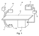
図1は、物体の細長い関心領域を撮像するための撮像システム10の一実施形態を概略的かつ例示的に示す。細長い関心領域は、例えば、脊椎、腹部大動脈、肺、又は物体若しくは患者の軸沿いに撮像システムの視野よりも大きい他の器官であり得る。
FIG. 1 schematically and exemplarily illustrates one embodiment of an
撮像システム10は、取得ユニット11及び処理ユニット13を備える。取得ユニット11はCアーム取得ユニットであり、X線源111及びX線検出器112を備える。撮像システム10はさらに、ユーザに情報及び制御を提供するための、ここではディスプレイの形態のインターフェースユニット14を備える。
The
患者テーブル21は、X線源111とX線検出器112との間に検査対象の物体又は患者(不図示)が位置するように配置されている。Cアームは、視方向を適合可能にするため、Cアームが物体の周りを移動できるよう設けられている。また、患者テーブル21が上に載置される基台22が検査室の床面に設けられている。
The patient table 21 is arranged so that an object to be examined or a patient (not shown) is located between the
Cアーム取得ユニット11は、物体固有データに基づき定められてもよい第1の幾何学的撮像パラメータを用いて、第1の回転スキャンで撮像対象の第1の画像データを取得するよう構成される。取得ユニット11は、さらに、物体固有データに基づき定められる第2の異なる幾何学的撮像パラメータを用いて、第2の回転スキャンで撮像対象の第2の画像データを取得するよう構成される。ボリュームデータを撮像対象の細長い関心領域に位置合わせさせる又は対応させるために、少なくとも第2の幾何学的撮像パラメータは、物体固有データに基づき定められる。処理ユニット13は、第1及び第2の画像データをボリュームデータに組み合わせるように構成されている。
The C-
図2に示されるように、Cアーム取得ユニット11による撮像は、例えば解剖学的データのような物体固有データに適合させることができる。言い換えれば、複数の単一の視野15は、ここでは湾曲した関心領域16を追跡し得る。これは、撮像システムの視野15の位置及び向きを解剖学的関心領域16に適合させることによって達成される。これにより、十分な解剖学的カバレッジのために可能な限り少ないスキャンが行われる。結果として、データの取り込み、よって照射量及びデータ処理の持続時間が低減される。
As shown in FIG. 2, the imaging by the C-
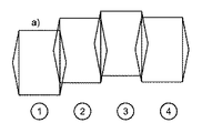
第1及び第2の撮像パラメータを定めるための基礎として使用される物体固有データは、例えば、プリインターベンションMR/CTデータセット等の患者固有スキャン計画データ、又は追加で若しくは代わりに、光学カメラシステムによって生成される表面モデル、CTスキャノグラムモードで取得されるX線投影セット、又はこれらの組み合わせであり得る。処理ユニット13は、第1の画像データ及び/又は第2の画像データ及び/又はボリュームデータを物体固有データを用いて組み合わせるように構成され得る。言い換えれば、物体固有データが利用可能な場合、撮像システム10は、これらのデータに基づき物体の細長い関心領域を撮像するために2つ以上の回転取得スキャンを実行することができる。詳細には、細長い関心領域の立体イメージを取得するために、例えばアイソセンター位置、取得ユニットの向き若しくは角度、又はX線検出器112の向き若しくはモード(ポートレート、ランドスケープ)等の2つ以上の回転Cアームスキャンのための幾何学的撮像パラメータが、物体固有データに基づき最適に選択され得る。好ましくは、パラメータは、Cアーム取得ユニットの個々の回転スキャンから融合及び再構成される立体イメージを、関心領域と最適に位置合わせするように選択される。図3に示すように、異なる幾何学的撮像パラメータ、すなわち異なる回転スキャンは、アイソセンター位置、取得ユニット11の向き、X線検出器112の向き、又はこれらの組み合わせによって区別され得る。
The object-specific data used as a basis for defining the first and second imaging parameters may be patient-specific scan planning data such as, for example, a pre-interventional MR/CT dataset, or additionally or alternatively, an optical camera system. Can be a surface model generated by, a set of X-ray projections acquired in CT scanogram mode, or a combination thereof. Processing
図3aによれば、第1の撮像パラメータについて、取得ユニット11は、第1のアイソセンター位置を有する回転スキャンで第1の画像データを取得する。第2の撮像パラメータについて、取得ユニット11は、第2のアイソセンター位置を有する回転スキャンで第2の画像データを取得する。第1及び第2のアイソセンター位置は、撮像システム10の取得方向とは異なる方向において互いに対して変位され、画像取得位置を関心領域に適合させる。取得方向は例えば脊椎沿いであり、第1及び第2のアイソセンター位置は、ここでは取得方向に対して垂直な方向において互いに対して変位される。図3a示す第3及び第4の撮像パラメータについても同様である。
According to Fig. 3a, for the first imaging parameter, the
第1のアイソセンター位置と第2のアイソセンター位置との間で可変なアイソセンター位置は、例えば、物体支持体若しくはテーブル高さの変更、又はCアーム取得ユニット11の配置若しくは対応する再配置によって達成され得る。具体的には、第1及び第2のアイソセンター位置は、物体支持体の高さ、物体の長手方向に対する物体支持体の長手方向位置、物体の横方向に対する物体支持体の横方向位置、取得ユニット11のCアームの位置、又はこれらの組み合わせからなる群のうちの少なくとも1つによって異なり得る。
The variable isocenter position between the first isocenter position and the second isocenter position can be determined, for example, by changing the height of the object support or the table, or by the arrangement or corresponding rearrangement of the C-
可変の第1及び第2の向きは、例えば、取得ユニット11全体の傾き又はそのX線検出器112の傾きによって達成することができる。
The variable first and second orientations can be achieved, for example, by the tilt of the
図3bによれば、Cアーム取得ユニット11の回転面は、第1の向きと第2の向きとの間で傾斜する。第1の撮像パラメータを用いて、取得ユニット11は、回転スキャン面の第1の向きで第1の画像データを取得する。第2の撮像パラメータを用いて、取得ユニット11は、回転スキャン面の異なる第2の向きで第2の画像データを取得する。第1及び第2の向きは、画像取得向きを関心領域に適合させるために、互いに対してある角度で傾斜されている。図3bにおいて、第3の回転スキャンのために、取得ユニット11は、第1及び第2の撮像パラメータに対して異なる第3の向き及び異なるアイソセンター位置の組み合わせで第3の画像データを取得する。第4の回転スキャンのために、取得ユニット11は、前回の撮像パラメータに対して異なる第4の向き及び異なるアイソセンター位置の組み合わせで第4の画像データを取得する。
According to FIG. 3b, the plane of rotation of the C-
図3cによれば、第1の撮像パラメータを用いて、取得ユニット11は、第1のアイソセンター位置で第1の画像データを取得する。第2の撮像パラメータを用いて、取得ユニット11は、第2のアイソセンター位置で第2の画像データを取得する。第3の撮像パラメータを用いて、取得ユニット11のX線検出器112は、ポートレートモード又は向きからランドスケープモード又は向きに回転する。ランドスケープ又はポートレートモード間のこの回転は90°になる。
According to FIG. 3c, using the first imaging parameter, the
図3a〜図3cにおいて、複数の回転スキャンで取得された画像データの視野は、互いに隣り合うよう配置される。スキャンの間に、取得ユニット(又は患者支持台)は、実質的に、各走査の再構成された視野の円錐形サブボリュームのみに小さい重なりが生じるよう、走査方向に移動される。 In FIGS. 3a to 3c, the fields of view of the image data acquired by the plurality of rotation scans are arranged adjacent to each other. During the scan, the acquisition unit (or patient support) is moved in the scan direction, such that substantially only a small overlap occurs in the conical subvolume of the reconstructed field of view of each scan.
画像データのボリュームデータへの結合は、異なる第1及び第2の2D画像データを2D画像データに縫い合わせ、その後2D画像データを3Dボリュームデータに再構成すること、又は異なる第1及び第2の2D画像データを異なる第1及び第2の3Dボリュームデータに再構成して、その後異なる第1及び第2の3Dボリュームデータを3Dボリュームデータに縫い合わせることと理解され得る。 The combination of the image data into the volume data may be performed by stitching different first and second 2D image data into 2D image data and then reconstructing the 2D image data into 3D volume data, or different first and second 2D image data. It can be understood that the image data is reconstructed into different first and second 3D volume data, and then the different first and second 3D volume data is sewn into the 3D volume data.
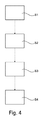
図4は、物体の細長い関心領域を撮像するための撮像方法の工程の概略全体図を示す。撮像方法は以下のステップを含むが、必ずしもこの順序である必要はない。
− 第1のステップS1において、Cアーム取得ユニット11の第1の幾何学的撮像パラメータを用いた回転スキャンで撮像対象の第1の画像データを取得する。
− 第2のステップS2において、Cアーム取得ユニット11の第2の幾何学的撮像パラメータを用いた回転スキャンで撮像対象の第2の画像データを取得する。ここで、少なくとも第2の異なる撮像パラメータは、撮像対象の細長い関心領域との位置合わせのために物体固有データに基づき定められる。
− 第3のステップS3において、第1の画像データと第2の画像データとをボリュームデータに合成する。
FIG. 4 shows a schematic overview of the steps of an imaging method for imaging an elongated region of interest of an object. The imaging method includes the following steps, but not necessarily in this order.
In the first step S1, the first image data of the imaging target is acquired by the rotation scan of the C-
In the second step S2, the second image data of the imaging target is acquired by the rotation scan using the second geometrical imaging parameter of the C-
In the third step S3, the first image data and the second image data are combined into volume data.
物体固有データは、患者固有解剖学的データとすることができる。 The object-specific data can be patient-specific anatomical data.
異なる第1及び第2の撮像パラメータは、アイソセンター位置、取得ユニット11の向き、そのX線検出器112の向き、又はこれらの組み合わせによって区別され得る。
The different first and second imaging parameters may be distinguished by the isocenter position, the orientation of the
第1及び第2の画像データのボリュームデータへの結合は、異なる第1及び第2の2D画像データを2D画像データに縫い合わせ、その後2D画像データを3Dボリュームデータに再構成すること、又は異なる第1及び第2の2D画像データを異なる第1及び第2の3Dボリュームデータに再構成して、その後異なる第1及び第2の3Dボリュームデータを3Dボリュームデータに縫い合わせることと理解され得る。 The combining of the first and second image data into the volume data may be performed by stitching different first and second 2D image data into 2D image data and then reconstructing the 2D image data into 3D volume data, or different first. It can be understood that the 1 and 2 2D image data are reconstructed into different 1st and 2D 3D volume data, and then the different 1st and 2D 3D volume data are sewn into the 3D volume data.
本発明の他の例示的な実施形態では、適切なシステム上で、上述の実施形態のうちの1つに係る方法の方法ステップを実行するよう構成されることを特徴とするコンピュータプログラム又はコンピュータプログラム要素が提供される。 In another exemplary embodiment of the invention, a computer program or a computer program characterized in that, on a suitable system, it is arranged to perform the method steps of the method according to one of the embodiments described above. Elements are provided.
したがって、コンピュータプログラム要素は、本発明の実施形態の一部であってもよいコンピュータユニットに保存されてもよい。このコンピュータユニットは、上記方法のステップを実行するよう、又はその実行を誘導するよう構成され得る。さらに、上記装置の構成要素を操作するよう構成されてもよい。コンピューティングユニットは、自動的に動作するようにかつ/又はユーザの指示を実行するように構成することができる。コンピュータプログラムは、データプロセッサの作業メモリにロードされてもよい。したがって、データプロセッサは、本発明の方法を実行するよう構成されてもよい。 Accordingly, computer program elements may be stored in a computer unit that may be part of an embodiment of the invention. This computer unit may be arranged to perform or direct the execution of the steps of the method. Further, it may be configured to operate the components of the device. The computing unit may be configured to operate automatically and/or execute user instructions. The computer program may be loaded into the working memory of the data processor. Therefore, the data processor may be arranged to carry out the method of the invention.
本発明のこの例示的な実施形態は、最初から本発明を使用するコンピュータプログラム、及び、更新によって既存のプログラムを本発明を使用するプログラムに変更するコンピュータプログラムの両方をカバーする。 This exemplary embodiment of the invention covers both a computer program that uses the invention from the start and a computer program that updates to transform an existing program into a program that uses the invention.
さらに、コンピュータプログラム要素は、上記の方法の例示的な実施形態の手順を満たすために必要な全てのステップを提供することが可能であり得る。 Moreover, the computer program element may be capable of providing all the steps necessary to fulfill the procedures of the exemplary embodiments of the method described above.
本発明のさらなる例示的実施形態によれば、上記のようなコンピュータプログラム要素が記憶されたCD−ROM等のコンピュータ可読媒体が提示される。 According to a further exemplary embodiment of the present invention there is presented a computer readable medium, such as a CD-ROM, having computer program elements as described above stored thereon.
コンピュータプログラムは、他のハードウェアと共に又は他のハードウェアの一部として供給される光学記憶媒体又はソリッドステート媒体等の適切な媒体上で記憶及び/又は分配されてもよいし、インターネット又は他の有線若しくは無線テレコミュニケーションシステムを介して等の他の形態で分配されてもよい。 The computer program may be stored and/or distributed on a suitable medium, such as an optical storage medium or a solid state medium supplied with or as part of other hardware, the internet or other It may be distributed in other forms, such as via a wired or wireless telecommunication system.
しかし、コンピュータプログラムは、ワールドワイドウェブのようなネットワークを介して提供され、かかるネットワークからデータプロセッサの作業メモリにダウンロードされてもよい。本発明の他の例示的な実施形態によれば、コンピュータプログラム要素をダウンロード可能にするための媒体が提供され、コンピュータプログラム要素は、本発明の上記実施形態の1つによる方法を実行するように構成される。 However, the computer program may be provided over a network such as the World Wide Web and downloaded from such a network into the working memory of the data processor. According to another exemplary embodiment of the present invention there is provided a medium for making a computer program element downloadable, the computer program element carrying out a method according to one of the above embodiments of the present invention. Composed.
本発明の実施形態は、異なる主題を参照して説明されていることに留意されたい。特に、一部の実施形態は方法タイプのクレームを参照して記載される一方、他の実施形態は装置スタイプのクレームを参照して記載される。しかし、当業者は上記及び下記の説明から、特に明記されない限り、1つのタイプの主題に属する特徴の組み合わせに加えて、異なる主題に関連する特徴の任意の組み合わせが、この出願に開示される解されることを理解するであろう。ただし、機能の単純な相加以上の相乗効果を提供するよう全ての機能が組み合わせ可能である。 It should be noted that embodiments of the present invention have been described with reference to different subject matter. In particular, some embodiments are described with reference to method type claims, while other embodiments are described with reference to apparatus type claims. However, from the description above and below, those skilled in the art will understand that, unless otherwise specified, combinations of features belonging to one type of subject matter, as well as any combination of features relating to different subject matter, are disclosed in this application. You will understand what is done. However, all features can be combined to provide a synergistic effect beyond simple addition of features.
本発明は、図面及び上記において詳細に図示及び記載されているが、かかる図示及び記載は説明的又は例示的であり、非限定的であると考えられるべきである。本発明は、開示の実施形態に限定されない。開示の実施形態の他の変形例が、図面、開示、及び従属請求項から、クレームされる発明に係る当業者によって理解及び実施され得る。 While the invention has been illustrated and described in detail in the drawings and foregoing description, such illustration and description are to be considered illustrative or exemplary and not restrictive. The invention is not limited to the disclosed embodiments. Other variations of the disclosed embodiments can be understood and effected by those skilled in the art in accordance with the claimed invention, from the drawings, the disclosure, and the dependent claims.
特許請求の範囲において、「含む(comprising)」という用語は他の要素又はステップを排除するものではなく、不定冠詞「a」又は「an」は複数を除外しない。単一のプロセッサ又は他のユニットが、請求項に記載される複数のアイテムの機能を果たし得る。複数の手段が互いに異なる従属請求項に記載されているからといって、これらの手段の組み合わせが好適に使用することができないとは限らない。特許請求の範囲内のいかなる参照符号も、その範囲を限定するものと解釈されるべきではない。 In the claims, the term "comprising" does not exclude other elements or steps, and the indefinite article "a" or "an" does not exclude a plurality. A single processor or other unit may fulfill the functions of several items recited in the claims. The mere fact that several measures are recited in mutually different dependent claims does not indicate that a combination of these measures cannot be used to advantage. Any reference signs in the claims shall not be construed as limiting the scope.
Claims (14)
Cアーム取得ユニットと、
処理ユニットとを含み、
前記取得ユニットは、第1の幾何学的撮像パラメータを用いた第1の回転スキャンで撮像対象の前記物体の第1の画像データを取得し、
前記取得ユニットは、前記第1の幾何学的撮像パラメータとは異なる第2の幾何学的撮像パラメータを用いて第2の回転スキャンで撮像対象の前記物体の第2の画像データを取得し、
前記処理ユニットは、前記第1の画像データ及び前記第2の画像データを結合してボリュームデータを生成し、
前記第2の幾何学的撮像パラメータは、前記ボリュームデータを撮像対象の前記物体の前記細長い関心領域と位置合わせするために、物体固有データに基づき定義可能である、撮像システム。 An imaging system for imaging an elongated region of interest in an object, comprising:
A C-arm acquisition unit,
Including a processing unit,
The acquisition unit acquires first image data of the object to be imaged in a first rotational scan using a first geometrical imaging parameter;
The acquisition unit acquires second image data of the object to be imaged in a second rotational scan using a second geometrical imaging parameter different from the first geometrical imaging parameter,
The processing unit combines the first image data and the second image data to generate volume data,
An imaging system, wherein the second geometric imaging parameter is definable based on object-specific data for registering the volume data with the elongated region of interest of the object to be imaged.
物体支持体の高さ、
前記物体の長手方向に対する物体支持体の長手方向位置、
前記物体の横方向に対する前記物体支持体の横方向位置、又は
前記取得ユニットのCアームの位置からなる群のうちの少なくとも1つによって異なる、請求項2に記載の撮像システム。 The first isocenter position and the second isocenter position are
The height of the object support,
The longitudinal position of the object support relative to the longitudinal direction of the object,
The imaging system according to claim 2, which differs depending on at least one of the group consisting of the lateral position of the object support with respect to the lateral direction of the object or the position of the C-arm of the acquisition unit.
第1の回転スキャンにおいて、Cアーム取得ユニットの第1の撮像パラメータを用いて撮像対象の前記物体の第1の画像データを取得するステップと、
第2の回転スキャンにおいて、前記Cアーム取得ユニットの、前記第1の撮像パラメータとは異なる第2の撮像パラメータを用いて撮像対象の前記物体の第2の画像データを取得するステップと、
前記第1の画像データと前記第2の画像データとを結合してボリュームデータを生成するステップとを含み、
さらに、前記ボリュームデータを撮像対象の前記物体の前記細長い関心領域と位置合わせさせるために、物体固有データに基づき、前記第2の撮像パラメータを定義するステップを含む、方法。 An imaging method for imaging an elongated region of interest of an object, comprising:
Acquiring a first image data of the object to be imaged using a first imaging parameter of a C-arm acquisition unit in a first rotation scan;
In a second rotation scan, using the second imaging parameter of the C-arm acquisition unit, which is different from the first imaging parameter, to acquire second image data of the object to be imaged;
Combining the first image data and the second image data to generate volume data,
The method further comprising defining the second imaging parameter based on object-specific data to align the volume data with the elongated region of interest of the object to be imaged.
A computer-readable medium in which the computer program according to claim 13 is stored.
Applications Claiming Priority (3)
| Application Number | Priority Date | Filing Date | Title |
|---|---|---|---|
| EP14198831 | 2014-12-18 | ||
| EP14198831.1 | 2014-12-18 | ||
| PCT/EP2015/080272 WO2016097174A1 (en) | 2014-12-18 | 2015-12-17 | Imaging system for imaging an elongated region of interest of an object |
Publications (3)
| Publication Number | Publication Date |
|---|---|
| JP2017537727A JP2017537727A (en) | 2017-12-21 |
| JP2017537727A5 JP2017537727A5 (en) | 2020-04-16 |
| JP6707542B2 true JP6707542B2 (en) | 2020-06-10 |
Family
ID=52278376
Family Applications (1)
| Application Number | Title | Priority Date | Filing Date |
|---|---|---|---|
| JP2017531993A Active JP6707542B2 (en) | 2014-12-18 | 2015-12-17 | Imaging system for imaging an elongated region of interest in an object |
Country Status (5)
| Country | Link |
|---|---|
| US (1) | US10561383B2 (en) |
| EP (1) | EP3232933B1 (en) |
| JP (1) | JP6707542B2 (en) |
| CN (1) | CN107106099B (en) |
| WO (1) | WO2016097174A1 (en) |
Families Citing this family (11)
| Publication number | Priority date | Publication date | Assignee | Title |
|---|---|---|---|---|
| JP7165053B2 (en) * | 2015-11-04 | 2022-11-02 | コーニンクレッカ フィリップス エヌ ヴェ | Device for imaging an object |
| EP3518767B1 (en) | 2016-09-29 | 2024-02-28 | Koninklijke Philips N.V. | Imaging system with dynamic beam size limitation |
| US11317886B2 (en) * | 2017-01-25 | 2022-05-03 | Canon Medical Systems Corporation | X-ray CT apparatus and imaging management apparatus |
| JP7098338B2 (en) * | 2017-01-25 | 2022-07-11 | キヤノンメディカルシステムズ株式会社 | X-ray CT device and imaging management device |
| JP6658578B2 (en) * | 2017-01-30 | 2020-03-04 | 株式会社島津製作所 | X-ray equipment |
| US10799183B2 (en) * | 2018-11-07 | 2020-10-13 | General Electric Company | Methods and systems for whole body imaging |
| DE202019003376U1 (en) | 2019-03-21 | 2019-09-13 | Ziehm Imaging Gmbh | X-ray system for iteratively determining an optimal coordinate transformation between overlapping volumes reconstructed from volume data sets of discretely scanned object areas |
| CN112472110A (en) * | 2019-09-12 | 2021-03-12 | 通用电气精准医疗有限责任公司 | X-ray imaging system and method |
| CN115024736A (en) * | 2021-03-04 | 2022-09-09 | 锐珂(上海)医疗器材有限公司 | Large-size imaging method and device based on digital radiography |
| CN117169255A (en) * | 2022-09-13 | 2023-12-05 | 埃尔西斯株式会社 | X-ray image generating method for detecting defect of object internal member |
| DE102022210292A1 (en) | 2022-09-28 | 2024-03-28 | Siemens Healthcare Gmbh | Computer-implemented method for operating an X-ray device, X-ray device, computer program and electronically readable data carrier |
Family Cites Families (19)
| Publication number | Priority date | Publication date | Assignee | Title |
|---|---|---|---|---|
| DE19959092A1 (en) | 1999-12-08 | 2001-06-13 | Philips Corp Intellectual Pty | Obtaining three-dimensional images of objects involves combining reconstruction images using weighted addition; each image is weighted using noise and/or artifact distribution function |
| US20020159564A1 (en) | 2001-04-30 | 2002-10-31 | Eastman Kodak Company | Mothod for acquiring a radiation image of a long body part using direct digital x-ray detectors |
| DE10211016A1 (en) * | 2002-03-13 | 2003-09-25 | Philips Intellectual Property | X-ray device with position-adjustable X-ray detector |
| EP1833372A1 (en) | 2004-12-28 | 2007-09-19 | Koninklijke Philips Electronics N.V. | A medical 3d x-ray imaging device with a rotating c-shaped arm |
| US7522701B2 (en) | 2005-12-20 | 2009-04-21 | General Electric Company | System and method for image composition using position sensors |
| DE102006002907B4 (en) | 2006-01-20 | 2011-06-16 | Siemens Ag | Method and device for reconstructing a three-dimensional image volume from two-dimensional projection images |
| CN101500488A (en) * | 2006-08-14 | 2009-08-05 | 皇家飞利浦电子股份有限公司 | Collecting images for image stitching with rotating a radiation detector |
| EP2074383B1 (en) * | 2006-09-25 | 2016-05-11 | Mazor Robotics Ltd. | C-arm computerized tomography |
| DE102007030962A1 (en) * | 2007-07-04 | 2009-01-15 | Siemens Ag | Method for obtaining measured data |
| WO2009133896A1 (en) * | 2008-04-30 | 2009-11-05 | 株式会社モリタ製作所 | Medical x-ray ct imaging device |
| JP4516626B1 (en) | 2009-09-28 | 2010-08-04 | 株式会社吉田製作所 | Dental X-ray equipment |
| DE102009047867B4 (en) | 2009-09-30 | 2016-10-06 | Siemens Healthcare Gmbh | Method and device for correcting truncated projection data |
| DE102010033116A1 (en) * | 2010-08-02 | 2012-02-02 | Siemens Aktiengesellschaft | Method for generating three-dimensional image data, involves performing mutual image registration of three-dimensional image data in overlap region and merging visual three-dimensional single-registered image data |
| DE102011006991B4 (en) | 2011-04-07 | 2018-04-05 | Siemens Healthcare Gmbh | X-ray method and X-ray device for assembling X-ray images and determining three-dimensional volume data |
| RU2634665C2 (en) * | 2011-11-11 | 2017-11-02 | Конинклейке Филипс Н.В. | System with c-type frame with extended imaging zone |
| DE102011089178B4 (en) | 2011-12-20 | 2017-12-28 | Siemens Healthcare Gmbh | Method for recording a projection image and imaging device |
| DE102012202360B4 (en) * | 2012-02-16 | 2023-09-21 | Siemens Healthcare Gmbh | Method for image acquisition of a two-dimensional projective X-ray image with a C-arm system and C-arm system |
| DE102012216652B4 (en) | 2012-09-18 | 2023-01-26 | Siemens Healthcare Gmbh | Angiographic examination procedure |
| WO2014165455A2 (en) * | 2013-04-04 | 2014-10-09 | Illinois Tool Works Inc. | Helical computed tomography |
-
2015
- 2015-12-17 WO PCT/EP2015/080272 patent/WO2016097174A1/en active Application Filing
- 2015-12-17 CN CN201580068801.4A patent/CN107106099B/en active Active
- 2015-12-17 JP JP2017531993A patent/JP6707542B2/en active Active
- 2015-12-17 US US15/535,667 patent/US10561383B2/en active Active
- 2015-12-17 EP EP15813062.5A patent/EP3232933B1/en active Active
Also Published As
| Publication number | Publication date |
|---|---|
| JP2017537727A (en) | 2017-12-21 |
| WO2016097174A1 (en) | 2016-06-23 |
| EP3232933B1 (en) | 2022-07-20 |
| CN107106099A (en) | 2017-08-29 |
| CN107106099B (en) | 2021-05-28 |
| US10561383B2 (en) | 2020-02-18 |
| EP3232933A1 (en) | 2017-10-25 |
| US20170340299A1 (en) | 2017-11-30 |
Similar Documents
| Publication | Publication Date | Title |
|---|---|---|
| JP6707542B2 (en) | Imaging system for imaging an elongated region of interest in an object | |
| JP6534998B2 (en) | Method and apparatus for displaying a medical image | |
| ES2716837T3 (en) | Automatic detection of implants from image artifacts | |
| JP6205078B2 (en) | Vertebral level imaging system | |
| US9858663B2 (en) | Method and system for tomosynthesis imaging | |
| US9262830B2 (en) | 2D/3D image registration | |
| JP2017537727A5 (en) | ||
| US20230091213A1 (en) | Field of view matching for mobile 3d imaging | |
| CN109394253B (en) | Apparatus and method for fine-tuning reconstruction plane of digital composite image | |
| US20120063565A1 (en) | Method for collimating to an off-center examination sub-object | |
| JP2011031039A (en) | Inclined image scanning method, reconstitution method, and device therefor | |
| US20070237287A1 (en) | Ct scanner with automatic determination of volume of interest | |
| JP6824641B2 (en) | X-ray CT device | |
| KR101525040B1 (en) | Method and Apparatus of Generation of reference image for determining scan range of pre-operative images | |
| US11123025B2 (en) | Iso-centering in C-arm computer tomography | |
| CN109425843A (en) | Method and system for magnetic resonance imaging | |
| EP4312188A1 (en) | Combined optical and non-optical 3d reconstruction | |
| JP6760510B2 (en) | Radiation imaging device |
Legal Events
| Date | Code | Title | Description |
|---|---|---|---|
| A621 | Written request for application examination |
Free format text: JAPANESE INTERMEDIATE CODE: A621 Effective date: 20181213 |
|
| A521 | Request for written amendment filed |
Free format text: JAPANESE INTERMEDIATE CODE: A523 Effective date: 20191002 |
|
| A871 | Explanation of circumstances concerning accelerated examination |
Free format text: JAPANESE INTERMEDIATE CODE: A871 Effective date: 20191002 |
|
| A977 | Report on retrieval |
Free format text: JAPANESE INTERMEDIATE CODE: A971007 Effective date: 20191125 |
|
| A975 | Report on accelerated examination |
Free format text: JAPANESE INTERMEDIATE CODE: A971005 Effective date: 20191202 |
|
| A131 | Notification of reasons for refusal |
Free format text: JAPANESE INTERMEDIATE CODE: A131 Effective date: 20191210 |
|
| A524 | Written submission of copy of amendment under article 19 pct |
Free format text: JAPANESE INTERMEDIATE CODE: A524 Effective date: 20200304 |
|
| TRDD | Decision of grant or rejection written | ||
| A01 | Written decision to grant a patent or to grant a registration (utility model) |
Free format text: JAPANESE INTERMEDIATE CODE: A01 Effective date: 20200421 |
|
| A61 | First payment of annual fees (during grant procedure) |
Free format text: JAPANESE INTERMEDIATE CODE: A61 Effective date: 20200520 |
|
| R150 | Certificate of patent or registration of utility model |
Ref document number: 6707542 Country of ref document: JP Free format text: JAPANESE INTERMEDIATE CODE: R150 |
|
| R250 | Receipt of annual fees |
Free format text: JAPANESE INTERMEDIATE CODE: R250 |