JP6707431B2 - Galvanic battery oxygen sensor - Google Patents
Galvanic battery oxygen sensor Download PDFInfo
- Publication number
- JP6707431B2 JP6707431B2 JP2016195132A JP2016195132A JP6707431B2 JP 6707431 B2 JP6707431 B2 JP 6707431B2 JP 2016195132 A JP2016195132 A JP 2016195132A JP 2016195132 A JP2016195132 A JP 2016195132A JP 6707431 B2 JP6707431 B2 JP 6707431B2
- Authority
- JP
- Japan
- Prior art keywords
- oxygen sensor
- citric acid
- positive electrode
- electrolytic solution
- holder
- Prior art date
- Legal status (The legal status is an assumption and is not a legal conclusion. Google has not performed a legal analysis and makes no representation as to the accuracy of the status listed.)
- Active
Links
- QVGXLLKOCUKJST-UHFFFAOYSA-N atomic oxygen Chemical compound [O] QVGXLLKOCUKJST-UHFFFAOYSA-N 0.000 title claims description 67
- 229910052760 oxygen Inorganic materials 0.000 title claims description 67
- 239000001301 oxygen Substances 0.000 title claims description 67
- KRKNYBCHXYNGOX-UHFFFAOYSA-N citric acid Chemical compound OC(=O)CC(O)(C(O)=O)CC(O)=O KRKNYBCHXYNGOX-UHFFFAOYSA-N 0.000 claims description 81
- 239000008151 electrolyte solution Substances 0.000 claims description 38
- 229960004106 citric acid Drugs 0.000 claims description 27
- YASYEJJMZJALEJ-UHFFFAOYSA-N Citric acid monohydrate Chemical compound O.OC(=O)CC(O)(C(O)=O)CC(O)=O YASYEJJMZJALEJ-UHFFFAOYSA-N 0.000 claims description 10
- 229910045601 alloy Inorganic materials 0.000 claims description 10
- 239000000956 alloy Substances 0.000 claims description 10
- 229910020935 Sn-Sb Inorganic materials 0.000 claims description 9
- 229910008757 Sn—Sb Inorganic materials 0.000 claims description 9
- 239000003054 catalyst Substances 0.000 claims description 9
- 229960002303 citric acid monohydrate Drugs 0.000 claims description 9
- 239000010931 gold Substances 0.000 claims description 8
- BASFCYQUMIYNBI-UHFFFAOYSA-N platinum Chemical compound [Pt] BASFCYQUMIYNBI-UHFFFAOYSA-N 0.000 claims description 8
- 229910052737 gold Inorganic materials 0.000 claims description 5
- PCHJSUWPFVWCPO-UHFFFAOYSA-N gold Chemical compound [Au] PCHJSUWPFVWCPO-UHFFFAOYSA-N 0.000 claims description 4
- 229910052709 silver Inorganic materials 0.000 claims description 4
- BQCADISMDOOEFD-UHFFFAOYSA-N Silver Chemical compound [Ag] BQCADISMDOOEFD-UHFFFAOYSA-N 0.000 claims description 3
- 229910052697 platinum Inorganic materials 0.000 claims description 3
- 239000004332 silver Substances 0.000 claims description 3
- 230000003197 catalytic effect Effects 0.000 claims 1
- 229910052751 metal Inorganic materials 0.000 description 14
- 239000002184 metal Substances 0.000 description 14
- 230000004044 response Effects 0.000 description 13
- 239000002738 chelating agent Substances 0.000 description 12
- 239000000463 material Substances 0.000 description 11
- 230000001681 protective effect Effects 0.000 description 11
- WABPQHHGFIMREM-UHFFFAOYSA-N lead(0) Chemical compound [Pb] WABPQHHGFIMREM-UHFFFAOYSA-N 0.000 description 8
- 239000010936 titanium Substances 0.000 description 8
- 229920000122 acrylonitrile butadiene styrene Polymers 0.000 description 7
- 229910052719 titanium Inorganic materials 0.000 description 6
- MYMOFIZGZYHOMD-UHFFFAOYSA-N Dioxygen Chemical compound O=O MYMOFIZGZYHOMD-UHFFFAOYSA-N 0.000 description 5
- RTAQQCXQSZGOHL-UHFFFAOYSA-N Titanium Chemical compound [Ti] RTAQQCXQSZGOHL-UHFFFAOYSA-N 0.000 description 5
- 229910001882 dioxygen Inorganic materials 0.000 description 5
- 239000011347 resin Substances 0.000 description 5
- 229920005989 resin Polymers 0.000 description 5
- 229910001128 Sn alloy Inorganic materials 0.000 description 4
- 239000000428 dust Substances 0.000 description 4
- 230000000694 effects Effects 0.000 description 4
- 239000012535 impurity Substances 0.000 description 4
- 238000012360 testing method Methods 0.000 description 4
- BFKJFAAPBSQJPD-UHFFFAOYSA-N tetrafluoroethene Chemical group FC(F)=C(F)F BFKJFAAPBSQJPD-UHFFFAOYSA-N 0.000 description 4
- XLYOFNOQVPJJNP-UHFFFAOYSA-N water Substances O XLYOFNOQVPJJNP-UHFFFAOYSA-N 0.000 description 4
- 239000000470 constituent Substances 0.000 description 3
- 229920001577 copolymer Polymers 0.000 description 3
- 238000012937 correction Methods 0.000 description 3
- 238000010586 diagram Methods 0.000 description 3
- 239000007789 gas Substances 0.000 description 3
- -1 polyethylene Polymers 0.000 description 3
- 238000006722 reduction reaction Methods 0.000 description 3
- 229920006395 saturated elastomer Polymers 0.000 description 3
- PXRKCOCTEMYUEG-UHFFFAOYSA-N 5-aminoisoindole-1,3-dione Chemical compound NC1=CC=C2C(=O)NC(=O)C2=C1 PXRKCOCTEMYUEG-UHFFFAOYSA-N 0.000 description 2
- KCXVZYZYPLLWCC-UHFFFAOYSA-N EDTA Chemical class OC(=O)CN(CC(O)=O)CCN(CC(O)=O)CC(O)=O KCXVZYZYPLLWCC-UHFFFAOYSA-N 0.000 description 2
- 239000004743 Polypropylene Substances 0.000 description 2
- 238000005273 aeration Methods 0.000 description 2
- 230000000052 comparative effect Effects 0.000 description 2
- 239000003792 electrolyte Substances 0.000 description 2
- 238000011156 evaluation Methods 0.000 description 2
- 239000000383 hazardous chemical Substances 0.000 description 2
- 239000007788 liquid Substances 0.000 description 2
- 238000005259 measurement Methods 0.000 description 2
- 150000002739 metals Chemical class 0.000 description 2
- 239000000203 mixture Substances 0.000 description 2
- 125000000896 monocarboxylic acid group Chemical group 0.000 description 2
- 230000002093 peripheral effect Effects 0.000 description 2
- 229920000515 polycarbonate Polymers 0.000 description 2
- 239000004417 polycarbonate Substances 0.000 description 2
- 229920001155 polypropylene Polymers 0.000 description 2
- 230000009467 reduction Effects 0.000 description 2
- NLJMYIDDQXHKNR-UHFFFAOYSA-K sodium citrate Chemical compound O.O.[Na+].[Na+].[Na+].[O-]C(=O)CC(O)(CC([O-])=O)C([O-])=O NLJMYIDDQXHKNR-UHFFFAOYSA-K 0.000 description 2
- 239000001509 sodium citrate Substances 0.000 description 2
- 229960000999 sodium citrate dihydrate Drugs 0.000 description 2
- 229910052718 tin Inorganic materials 0.000 description 2
- HRXKRNGNAMMEHJ-UHFFFAOYSA-K trisodium citrate Chemical compound [Na+].[Na+].[Na+].[O-]C(=O)CC(O)(CC([O-])=O)C([O-])=O HRXKRNGNAMMEHJ-UHFFFAOYSA-K 0.000 description 2
- 229920000181 Ethylene propylene rubber Polymers 0.000 description 1
- UFHFLCQGNIYNRP-UHFFFAOYSA-N Hydrogen Chemical compound [H][H] UFHFLCQGNIYNRP-UHFFFAOYSA-N 0.000 description 1
- 229920000459 Nitrile rubber Polymers 0.000 description 1
- 239000004698 Polyethylene Substances 0.000 description 1
- 230000009471 action Effects 0.000 description 1
- 229910052782 aluminium Inorganic materials 0.000 description 1
- 229910052797 bismuth Inorganic materials 0.000 description 1
- 229910052791 calcium Inorganic materials 0.000 description 1
- 230000008859 change Effects 0.000 description 1
- 235000020971 citrus fruits Nutrition 0.000 description 1
- 229910052802 copper Inorganic materials 0.000 description 1
- 230000007797 corrosion Effects 0.000 description 1
- 238000005260 corrosion Methods 0.000 description 1
- 239000013078 crystal Substances 0.000 description 1
- 230000027734 detection of oxygen Effects 0.000 description 1
- 238000003487 electrochemical reaction Methods 0.000 description 1
- 238000002149 energy-dispersive X-ray emission spectroscopy Methods 0.000 description 1
- 150000004677 hydrates Chemical class 0.000 description 1
- 229910052739 hydrogen Inorganic materials 0.000 description 1
- 239000001257 hydrogen Substances 0.000 description 1
- 150000001261 hydroxy acids Chemical class 0.000 description 1
- 230000006872 improvement Effects 0.000 description 1
- 229910052738 indium Inorganic materials 0.000 description 1
- 230000009545 invasion Effects 0.000 description 1
- 229910052742 iron Inorganic materials 0.000 description 1
- 229910052749 magnesium Inorganic materials 0.000 description 1
- 238000004519 manufacturing process Methods 0.000 description 1
- 230000007246 mechanism Effects 0.000 description 1
- 238000012986 modification Methods 0.000 description 1
- 230000004048 modification Effects 0.000 description 1
- 229910052759 nickel Inorganic materials 0.000 description 1
- 210000000056 organ Anatomy 0.000 description 1
- 150000002894 organic compounds Chemical class 0.000 description 1
- 229920000573 polyethylene Polymers 0.000 description 1
- 229920000098 polyolefin Polymers 0.000 description 1
- 230000000241 respiratory effect Effects 0.000 description 1
- 150000003839 salts Chemical class 0.000 description 1
- 229910052711 selenium Inorganic materials 0.000 description 1
- 229920002379 silicone rubber Polymers 0.000 description 1
- 239000004945 silicone rubber Substances 0.000 description 1
- 229910052708 sodium Inorganic materials 0.000 description 1
- 239000011734 sodium Substances 0.000 description 1
- 159000000000 sodium salts Chemical class 0.000 description 1
- 241000894007 species Species 0.000 description 1
- 230000000087 stabilizing effect Effects 0.000 description 1
- 239000000126 substance Substances 0.000 description 1
- 229910052717 sulfur Inorganic materials 0.000 description 1
- 238000009423 ventilation Methods 0.000 description 1
- 229910052725 zinc Inorganic materials 0.000 description 1
Images

Landscapes
- Electrolytic Production Of Non-Metals, Compounds, Apparatuses Therefor (AREA)
Description
本発明は、ガルバニ電池式酸素センサに関する。 The present invention relates to a galvanic battery type oxygen sensor.
ガルバニ電池式酸素センサ(以下、酸素センサともいう)は、安価、手軽、且つ常温での作動が可能という利点を有することから、船倉内部やマンホール内の酸欠状態のチェック、又は麻酔器や人工呼吸器などの医療機器における酸素濃度の検出など広い分野で使用されている。 The galvanic battery oxygen sensor (hereinafter also referred to as the oxygen sensor) has the advantages of being inexpensive, convenient, and capable of operating at room temperature. It is used in a wide range of fields such as the detection of oxygen concentration in medical devices such as respiratory organs.
このようなガルバニ電池式酸素センサを含む電気化学式酸素センサとして、特許文献1には、「カソード、アノード、及び電解液を備えた電気化学式酸素センサにおいて、前記電解液にキレート剤が含まれていることを特徴とする電気化学式酸素センサ」(請求の範囲[1])が開示されている。また、特許文献1には、発明の効果として、「本発明によれば、応答速度が速い電気化学式酸素センサを提供することができる。」(段落[0015])と開示されている。 As an electrochemical oxygen sensor including such a galvanic cell type oxygen sensor, Patent Document 1 discloses that in an electrochemical oxygen sensor including a cathode, an anode, and an electrolytic solution, the electrolytic solution contains a chelating agent. An electrochemical oxygen sensor" (claim [1]) is disclosed. Further, Patent Document 1 discloses that, as an effect of the invention, "the present invention can provide an electrochemical oxygen sensor having a fast response speed." (paragraph [0015]).
しかしながら、特許文献1に記載されたキレート剤を電解液に用いた場合、酸素センサとしての寿命向上には限界があるものであった。
本発明は、上記課題を解決するためになされたものであり、応答速度が速く、かつ、酸素センサとしての寿命も向上することができるガルバニ電池式酸素センサを提供することを目的とする。
However, when the chelating agent described in Patent Document 1 is used in the electrolytic solution, there is a limit to the improvement of the life of the oxygen sensor.
The present invention has been made to solve the above problems, and an object of the present invention is to provide a galvanic battery type oxygen sensor that has a high response speed and can also have a long life as an oxygen sensor.
本発明に係るガルバニ電池式酸素センサは、ホルダーと、前記ホルダー内に収容された正極、負極及び電解液を備え、前記電解液にはクエン酸が含まれていることを特徴とする。 The galvanic cell oxygen sensor according to the present invention includes a holder, a positive electrode, a negative electrode, and an electrolytic solution housed in the holder, and the electrolytic solution contains citric acid.
本発明によれば、応答速度が速く、かつ、酸素センサとしての寿命も向上することができるガルバニ電池式酸素センサが提供される。 According to the present invention, there is provided a galvanic battery type oxygen sensor which has a high response speed and can also have a long life as an oxygen sensor.
本発明の構成及び作用効果について、技術的思想を交えて説明する。但し、作用機構については推定を含んでおり、その正否は、本発明を制限するものではない。また、以下の実施形態における構成要素のうち、最上位概念を示す独立請求項に記載されていない構成要素については、任意の構成要素として説明される。 The configuration and operational effects of the present invention will be described with a technical idea. However, the action mechanism includes estimation, and the correctness thereof does not limit the present invention. Further, among the constituent elements in the following embodiments, the constituent elements that are not described in the independent claims showing the highest concept are described as arbitrary constituent elements.
本発明者は、酸素センサとしての寿命が電解液中に含まれるキレート剤の含有量(濃度)と一致することを見出した。
そこで本発明者は、電解液中にキレート剤が含まれる酸素センサの寿命を高めるためには、電解液中にキレート剤を可能な限り多く溶解させること(すなわち、溶解度が高いキレート剤を用いること)が重要であることを見出し、本発明を完成するに至った。
The present inventor has found that the life as an oxygen sensor matches the content (concentration) of the chelating agent contained in the electrolytic solution.
Therefore, in order to extend the life of the oxygen sensor containing the chelating agent in the electrolytic solution, the present inventor should dissolve the chelating agent in the electrolytic solution as much as possible (that is, use a chelating agent having high solubility). ) Is important, and the present invention has been completed.
以下、本発明の好適な一実施形態(以下、「本実施形態」と記載する)として、ガルバニ電池式酸素センサを用いて具体的に説明する。
ガルバニ電池式酸素センサは、電気化学式酸素センサのうち正極と負極の間に抵抗を接続したものである。具体的には、ガルバニ電池式酸素センサは、正極上の電気化学的な酸素の還元によって生じた電流が前記抵抗において電圧に変換され、当該電圧に変換される電流と酸素濃度とは比例関係を有するので、前記電圧を測定することによって未知の気体中の酸素濃度を検出することができる。
Hereinafter, as a preferred embodiment of the present invention (hereinafter referred to as “the present embodiment”), a galvanic cell type oxygen sensor will be specifically described.
The galvanic cell oxygen sensor is an electrochemical oxygen sensor having a resistor connected between a positive electrode and a negative electrode. Specifically, in the galvanic cell type oxygen sensor, a current generated by electrochemical reduction of oxygen on the positive electrode is converted into a voltage at the resistance, and the current converted into the voltage and the oxygen concentration have a proportional relationship. Therefore, the oxygen concentration in the unknown gas can be detected by measuring the voltage.
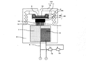
図1は、本実施形態に係るガルバニ電池式酸素センサの断面構造を示す概念図である。
図1において、1は第1ホルダー蓋(中蓋)、2はO−リング、3は隔膜へのゴミ、チリの付着あるいは、水膜付着を防止するための保護膜、4Aは隔膜、4Bは触媒電極、5は正極集電体、6は正極リード線、7は電解液、8は負極、9はホルダー、10は第2ホルダー蓋(外蓋)、11は電解液供給用の穿孔、12はリード線用の穿孔、13は正極集電体保持部、14は補正抵抗、15は温度補償用サーミスタである。触媒電極4Bと正極集電体5とで正極45を構成する。また、第1ホルダー蓋1と第2ホルダー蓋10とでホルダー蓋101を構成する。
FIG. 1 is a conceptual diagram showing a cross-sectional structure of a galvanic cell type oxygen sensor according to the present embodiment.
In FIG. 1, 1 is a first holder lid (interior lid), 2 is an O-ring, 3 is a protective film for preventing dust and dust from adhering to a diaphragm, or a water film is attached, 4A is a diaphragm, and 4B is a diaphragm. A catalyst electrode, 5 is a positive electrode current collector, 6 is a positive electrode lead wire, 7 is an electrolytic solution, 8 is a negative electrode, 9 is a holder, 10 is a second holder lid (outer lid), 11 is a hole for supplying an electrolytic solution, 12 Is a hole for a lead wire, 13 is a positive electrode current collector holding portion, 14 is a correction resistor, and 15 is a temperature compensating thermistor. The
本発明に係るガルバニ電池式酸素センサは、図1に示すような実施形態を一例とするものであって、ホルダー9と、ホルダー9内に収容された正極45、負極8及び電解液7を備え、前記電解液7にはクエン酸が含まれていることを特徴とする。
The galvanic cell oxygen sensor according to the present invention is, for example, an embodiment shown in FIG. 1, and includes a
ホルダー9は、その内部に正極45、負極8及び電解液7を収容するように構成されている。ホルダー9の材質は、後述する電解液7による腐食等の問題が無ければ特に限定されないが、ABS樹脂が好適に用いられる。
正極45は、ホルダー9内に収容されている。正極45の材質は、正極上の電気化学的な酸素の還元によって電流が生じれば特に限定されないが、金(Au)、銀(Ag)、白金(Pt)あるいはチタン(Ti)が好適に用いられる。
The
The
電解液7は、前記ホルダー9内に収容されている。また、電解液7にはクエン酸が含まれている。
本発明でいう「クエン酸」とは、本発明の要旨(応答速度が速く、かつ、酸素センサとしての寿命も向上することができるガルバニ電池式酸素センサの提供、以下同じ。)を逸脱しない限りにおいて、クエン酸(示性式 C(OH)(CH2COOH)2COOHで、柑橘類などに含まれる有機化合物であり、ヒドロキシ酸のひとつ)に加え、その水和物(クエン酸一水和物など)や、クエン酸又はその水和物の塩(クエン酸ナトリウム、クエン酸ナトリウム二水和物など)が含まれる。
また、本発明でいう「電解液にはクエン酸が含まれている」とは、本発明の要旨を逸脱しない限りにおいて、電解液7中にクエン酸が含まれていればよいことを意味し、電解液7中のクエン酸の種類や濃度には特に限定されない。また、電解液7中には、本発明の要旨を逸脱しない限りにおいて、クエン酸以外の他の成分が含有していてもよい。
The
The term “citric acid” as used in the present invention does not depart from the gist of the present invention (providing a galvanic cell type oxygen sensor which has a fast response speed and can also have a long life as an oxygen sensor, the same applies hereinafter). In addition to citric acid (the chemical formula C(OH)(CH 2 COOH) 2 COOH, an organic compound contained in citrus fruits and one of the hydroxy acids), its hydrate (citric acid monohydrate) Etc.) and salts of citric acid or hydrates thereof (sodium citrate, sodium citrate dihydrate, etc.).
In addition, the term “electrolytic solution contains citric acid” in the present invention means that the
本発明に係るガルバニ電池式酸素センサは、前記電解液中にクエン酸が含まれているため、キレート剤効果により応答速度が速くなり、かつ、酸素センサとしての寿命も向上させることができる。すなわち、クエン酸は、水への溶解度が特許文献1記載の他のキレート剤に比べて高い(クエン酸:73g/100ml(20℃)、クエン酸一水和物:163g/100ml(20℃)、クエン酸ナトリウム:42.5g/100ml(25℃)、クエン酸ナトリウム二水和物:77g/100ml(20℃)等)ため、電解液中にキレート剤を可能な限り多く溶解させることができる。従って、電解液中に含まれるキレート剤の含有量(濃度)を他のキレート剤(例えば、EDTA・四ナトリウム塩:60g/100ml(22℃))よりも高めることができるため、酸素センサとしての寿命を向上させることができる。 Since the galvanic cell type oxygen sensor according to the present invention contains citric acid in the electrolytic solution, the response speed becomes faster due to the chelating agent effect, and the life as an oxygen sensor can be improved. That is, citric acid has higher solubility in water than other chelating agents described in Patent Document 1 (citric acid: 73 g/100 ml (20° C.), citric acid monohydrate: 163 g/100 ml (20° C.). , Sodium citrate: 42.5 g/100 ml (25° C.), sodium citrate dihydrate: 77 g/100 ml (20° C.), etc., so that the chelating agent can be dissolved in the electrolytic solution as much as possible. .. Therefore, since the content (concentration) of the chelating agent contained in the electrolytic solution can be made higher than that of other chelating agents (for example, EDTA/tetrasodium salt: 60 g/100 ml (22°C)), it can be used as an oxygen sensor. The life can be improved.
前記電解液中に含まれるクエン酸の濃度は、応答速度を速くする観点から、0.001mol/L以上であることが好ましく、より好ましくは、0.005mol/L以上である。
本発明に係るガルバニ電池式酸素センサを医療機器に適用する場合など厳格な要件が求められる場合には、前記クエン酸の濃度は、0.1mol/L以上であることが好ましく、1.0mol/L以上であることが更に好ましい。
一方、前記電解液中に含まれるクエン酸の濃度の上限値は、クエン酸が高濃度になるほど酸素センサとしての寿命を高めることができるため、前記電解液中にクエン酸が飽和する濃度(飽和濃度)であることが好ましい。
The concentration of citric acid contained in the electrolytic solution is preferably 0.001 mol/L or more, and more preferably 0.005 mol/L or more, from the viewpoint of increasing the response speed.
When strict requirements are required, such as when the galvanic cell oxygen sensor according to the present invention is applied to a medical device, the concentration of citric acid is preferably 0.1 mol/L or more, and 1.0 mol/L. It is more preferably L or more.
On the other hand, the upper limit value of the concentration of citric acid contained in the electrolytic solution is such that the higher the concentration of citric acid is, the longer the life as an oxygen sensor can be. (Concentration).
前記クエン酸は、クエン酸一水和物を含むことが好ましい。
クエン酸一水和物は、他の種類のクエン酸に比べて、水への溶解度が高いため、電解液中により多く溶解させることができる。従って、より酸素センサとしての寿命を向上させることができる。
The citric acid preferably includes citric acid monohydrate.
Since citric acid monohydrate has higher solubility in water than other types of citric acid, it can be more dissolved in the electrolytic solution. Therefore, the life of the oxygen sensor can be further improved.
負極8は、前記ホルダー9内に収容されている。
負極8の材質は、本発明の要旨を逸脱しない限りにおいて、特に限定されない。前記負極8は、Cu、Fe、Ag、Ti、Al、Mg、Zn、Ni、Sn、及びそれらの合金(以下、負極金属という)を用いることができる。
また、負極8の材質は、本発明の要旨を逸脱しない限りにおいて、前記負極金属以外の金属やその他不純物が含まれていてもよい。前記負極金属以外の金属やその他不純物としては、In、Au、Bi、Na、S、Se及びCaが挙げられる。
The negative electrode 8 is housed in the
The material of the negative electrode 8 is not particularly limited without departing from the gist of the present invention. For the negative electrode 8, Cu, Fe, Ag, Ti, Al, Mg, Zn, Ni, Sn, and alloys thereof (hereinafter referred to as negative electrode metal) can be used.
Further, the material of the negative electrode 8 may contain a metal other than the negative electrode metal or other impurities, without departing from the scope of the present invention. Examples of metals and other impurities other than the negative electrode metal include In, Au, Bi, Na, S, Se and Ca.
前記負極8は、Sn合金であることが好ましく、より好ましくはSn−Sb合金である。
Sn合金は酸素センサにおける電気化学的な酸素の還元反応時において、水素の発生を抑制することができる。
また、Sn−Sb合金は、他のSn合金と比べて金属結晶間の金属結合力が高いと考えられるため、電解液7中に含まれるクエン酸の効果によって、応答速度が速くなり、かつ、酸素センサとしての寿命が向上した場合であっても、前記負極8起因による出力安定性の低下を抑制することができる。
The negative electrode 8 is preferably a Sn alloy, more preferably a Sn-Sb alloy.
The Sn alloy can suppress the generation of hydrogen during the electrochemical oxygen reduction reaction in the oxygen sensor.
Further, the Sn-Sb alloy is considered to have a higher metal binding force between metal crystals than other Sn alloys, and therefore the response speed is increased by the effect of citric acid contained in the
前記負極又は前記Sn−Sb合金は、実質的に鉛を含まないことが好ましい。
ここでいう「実質的に鉛を含まない」とは、負極8中に含まれるPbの含有量が1000ppm未満であることをいう。このようなSn−Sb合金を用いることで、EU(欧州連合)での特定有害物質の使用規制に関する指令[いわゆるRoHS指令(Restriction of the Use of Certain Hazardous Substances in Electrical and Electronic Equipment)]にも対応可能な電気化学式酸素センサを得ることができる。
It is preferable that the negative electrode or the Sn—Sb alloy contains substantially no lead.
The term “substantially free of lead” as used herein means that the content of Pb contained in the negative electrode 8 is less than 1000 ppm. By using such an Sn-Sb alloy, the EU (European Union) directive on the use of specific hazardous substances [also known as the RoHS directive (Restriction of the Use of Certain Hazardous Substances in Electrical and Electronic)]. A possible electrochemical oxygen sensor can be obtained.
Sn−Sb合金中のSn以外の金属(Sb)の含有量は、本発明の要旨を逸脱しない限りにおいて、特に限定されない。
本発明において、Sn−Sb合金中のSn以外の金属(Sb)の含有量は、測定するSn−Sbの任意の箇所に対して、EDX分析(ビーム径:1mm)を行い、そこで測定される金属元素全体に対するSbの重量%(Sn+Sb+「Sn及びSb以外の金属やその他不純物」=100%とする。)である。
The content of the metal (Sb) other than Sn in the Sn—Sb alloy is not particularly limited as long as it does not depart from the gist of the present invention.
In the present invention, the content of the metal (Sb) other than Sn in the Sn-Sb alloy is measured by performing EDX analysis (beam diameter: 1 mm) on an arbitrary position of Sn-Sb to be measured. It is the weight% of Sb with respect to the whole metal element (Sn+Sb+“metals other than Sn and Sb and other impurities”=100%).
本実施形態に係るガルバニ電池式酸素センサは、より具体的には、図1に示すように、ホルダー9と、前記ホルダー9内に収容された正極45、負極8及び電解液7と、前記正極45上に設けられた隔膜4Aと、前記隔膜4A上に設けられた保護膜3と、前記保護膜3を固定する第1ホルダー蓋(中蓋)1と、前記ホルダー9と前記中蓋1との間に配置されるO−リング2と、前記中蓋1を固定する第2ホルダー蓋(外蓋)10と、前記正極45及び負極8に直列に連結された補正抵抗14及び温度補償用サーミスタ15と、を備える。また、前記外蓋10と前記中蓋1とで構成されるホルダー蓋101には、前記保護膜3に通ずる酸素供給経路(空間)となる貫通孔16が設けられる。
More specifically, the galvanic cell type oxygen sensor according to the present embodiment is, as shown in FIG. 1, a
ホルダー9は、上部に開口を有し、該開口の外周に、ネジ山及びネジ溝からなり、外蓋10を螺合するためのネジ部が設けられている。
The
正極45は、酸素を電気化学的に還元する触媒電極4Bと、その電解液7側に配置された正極集電体5とから構成される。触媒電極4Bとしては、通常、金(Au)、銀(Ag)、あるいは白金(Pt)等が使用され、正極集電体5としては、通常、チタン(Ti)が使用されるが、いずれの材質もこれらに限定されるものではない。
The
前記正極集電体5の下側には、これを保持する正極集電体保持部13が設けられている。
この正極集電体保持部13には、正極45に電解液を供給するための穿孔11及び正極リード線6を通すための穿孔12が設けられている。
正極集電体保持部13の材質は特に限定されるものではないが、通常、ABS樹脂が使用される。
Below the positive electrode
The positive electrode
The material of the positive electrode
本実施形態における隔膜4Aは、触媒電極4Bに到達する酸素が多くなりすぎないように、酸素の侵入を制御するために配置される。隔膜4Aとしては、酸素を選択的に透過させると共に、酸素ガスの透過量を制限できるものが好ましい。隔膜4Aの材質は特に限定されるものではないが、通常、四フッ化エチレン樹脂,四フッ化エチレン六フッ化プロピレンコポリマー等のフッ素樹脂、ポリエチレン等のポリオレフィン等が使用される。
The
本実施形態における保護膜3は、隔膜4A上に設けられる多孔性樹脂膜であり、該隔膜4Aへのゴミ、チリの付着あるいは、水膜付着を防止する機能を有する。保護膜3の材質は特に限定されるものではないが、通常、四フッ化エチレン樹脂等のフッ素樹脂が使用される。
The
本実施形態における中蓋1は、保護膜3及び正極45の押圧端板として機能するものであり、ホルダー9と外蓋10とのネジ締めによって、O−リング2を介してホルダー9に押し付けられることで、気密性及び液密性を保持した状態で保護膜3及び正極45を前記ホルダー9に固定できるようになっている。中蓋1の材質は特に限定されるものではないが、通常、ABS樹脂、ポリプロピレン、ポリカーボネート、フッ素樹脂等が使用される。
The inner lid 1 in this embodiment functions as a pressing end plate for the
本実施形態におけるO−リング2は、ホルダー9と中蓋1との間に配置され、ホルダー9と外蓋10とのネジ締めによって押圧されて変形することで、気密性及び液密性を保持できるようになっている。O−リング2の材質は特に限定されるものではないが、通常、ニトリルゴム、シリコーンゴム、エチレンプロピレンゴム、フッ素樹脂等が使用される。
The O-
本実施形態における外蓋10は、O−リング2及び中蓋1と共に、ホルダー9の開口を密閉するように構成されており、ホルダー9の開口の外周部に形成されたネジ部と螺合するように、内周部にネジ部が形成されている。外蓋1の材質は特に限定されるものではないが、通常、ABS樹脂、ポリプロピレン、ポリカーボネート、フッ素樹脂等が使用される。
The
なお、本発明は上述した実施形態に限られるものではなく、その技術的思想の範囲内で種々の変更が可能である。
例えば、図1における記号1〜15は、これに限定されることなく、酸素センサとしての機能及び前述した酸素供給経路を備えていれば、各種設計変更が可能である。
また、本実施形態では、ガルバニ電池式酸素センサを用いて説明したが、本発明は、定電位式酸素センサにも適用することができる。
定電位式酸素センサは、正極と負極との間に一定電圧を印加するセンサであり、印加電圧は各電極の電気化学特性や検知するガス種に応じて設定される。定電位式酸素センサでは正極と負極の間に適当な一定電圧を印加すると、その間に流れる電流と酸素ガス濃度とは比例関係を有するので、電流を電圧に変換すれば、ガルバニ電池式酸素センサと同様に、電圧を測定することによって未知の気体の酸素ガス濃度を検出することができる。
The present invention is not limited to the above-described embodiment, and various modifications can be made within the scope of its technical idea.
For example, the symbols 1 to 15 in FIG. 1 are not limited to this, and various designs can be changed as long as the function as an oxygen sensor and the oxygen supply path described above are provided.
Further, although the present embodiment has been described using the galvanic cell type oxygen sensor, the present invention can also be applied to a constant potential type oxygen sensor.
The constant potential oxygen sensor is a sensor that applies a constant voltage between the positive electrode and the negative electrode, and the applied voltage is set according to the electrochemical characteristics of each electrode and the gas species to be detected. In a constant-potential oxygen sensor, when an appropriate constant voltage is applied between the positive electrode and the negative electrode, the current flowing between them has a proportional relationship with the oxygen gas concentration. Similarly, the oxygen gas concentration of an unknown gas can be detected by measuring the voltage.
次に、本発明を実施例に基づいて更に具体的に説明するが、本発明はこれらに限定されるものではない。
(実施例1〜4)
図1に示すガルバニ電池式酸素センサを作製した。なお、図1において、中蓋1はABS樹脂製、保護膜3は多孔性の四フッ化エチレン樹脂製シート、隔膜4Aは四フッ化エチレン六フッ化プロピレンコポリマー膜、触媒電極4Bは金(Au)、正極集電体5はチタン製、正極リード線6はチタン製、正極集電体5と正極リード線6は溶接して一体化されている。
Next, the present invention will be described more specifically based on examples, but the present invention is not limited thereto.
(Examples 1 to 4)
The galvanic cell type oxygen sensor shown in FIG. 1 was produced. In FIG. 1, the inner lid 1 is made of ABS resin, the
また、負極8はSn−5.0Sb合金(左数字は、上述したように、Sn合金中のSbの重量%(Sn+他の金属+「Sn及び他の金属以外の金属やその他不純物」=100%とする。)、電解液7は(実施例1)クエン酸、(実施例2)クエン酸一水和物、(実施例3)クエン酸とクエン酸一水和物の混合物(混合比=1:1)、ホルダー本体9はABS樹脂製、外蓋10はABS樹脂製であり、ホルダー本体9および外蓋10には、それぞれネジが切られている。
なお、それぞれの電解液((実施例1)クエン酸、(実施例2)クエン酸一水和物、(実施例3)クエン酸とクエン酸一水和物の混合物)は、それぞれ電解液中において飽和濃度とした。
In addition, the negative electrode 8 is a Sn-5.0Sb alloy (the left number is, as described above, the weight% of Sb in the Sn alloy (Sn + other metal + "metal other than Sn and other metal and other impurities" = 100). %), and the
Each of the electrolytic solutions ((Example 1) citric acid, (Example 2) citric acid monohydrate, (Example 3) mixture of citric acid and citric acid monohydrate) was used in the electrolytic solution. Was the saturation concentration.
中蓋1、O−リング2、四フッ化エチレン樹脂製シート(保護膜)3、四フッ化エチレン六フッ化プロピレンコポリマー膜の隔膜4A、触媒電極4B、正極集電体5は、ホルダー本体9と外蓋10とのネジ締めによって押圧され良好な接触状態が保持される。中蓋1は押圧端板として機能し、また、O−リング2によって気密、液密性が確保されている。
11は正極および隔膜への電解液供給用の穿孔、12は正極集電体のチタンリード線部分を通すための穿孔である。
The inner lid 1, the O-
(比較例1)
キレート剤としてクエン酸ではなく、EDTA・4ナトリウム塩を用い、電解液中では飽和濃度として、その他は実施例1と同様の図1に示す1年寿命のガルバニ電池式酸素センサを作製した。
(Comparative Example 1)
A 1-year-old galvanic cell type oxygen sensor shown in FIG. 1 was manufactured as in Example 1 except that EDTA.4 sodium salt was used as the chelating agent, and the concentration was saturated in the electrolyte solution.
[特性比較]
前記作製した複数のガルバニ電池式酸素センサに関し、作成後2ヶ月後の「90%応答速度」を評価した。90%応答速度は、大気中(酸素濃度21%)で各センサの出力が安定した状態にしてから、当該出力が安定したセンサに対して、濃度が100%酸素を通気し、当該濃度100%の酸素を通気することにより生じ得る出力(飽和出力)を100%として出力が90%変化するまでに要する時間を測定した。本評価試験においては、通気30分後の出力を飽和出力とした。上記評価試験により得られた結果を表1に示した。表1において、○は、90%応答速度が15秒未満であることを意味し、△は応答速度が15秒以上60秒未満を意味し、×は、応答速度が60秒以上であることを意味する。
[Characteristic comparison]
With respect to the plurality of galvanic battery type oxygen sensors thus produced, "90% response speed" was evaluated two months after the production. The 90% response speed is obtained by stabilizing the output of each sensor in the air (oxygen concentration 21%), and then aeration of 100% oxygen is passed to the sensor whose output is stable. The time required for the output to change by 90% was measured by setting the output (saturated output) that can be generated by aeration of oxygen of 100% as 100%. In this evaluation test, the output after 30 minutes of ventilation was taken as the saturated output. The results obtained by the above evaluation test are shown in Table 1. In Table 1, ◯ means that the 90% response speed is less than 15 seconds, Δ means that the response speed is 15 seconds or more and less than 60 seconds, and x means that the response speed is 60 seconds or more. means.
また、前記作製した複数のガルバニ電池式酸素センサを、360日間、同環境下、常温(25℃)で放置し、酸素センサの出力電圧が安定しているかどうかを評価した。なお、ここでいう出力電圧が安定するとは、図2に示すように、横軸を測定時間、縦軸を出力電圧として、測定時間における出力電圧の傾向をプロットした場合に、図2に示すような直線を描く場合をいう。 Further, the plurality of galvanic battery type oxygen sensors prepared above were left for 360 days in the same environment at room temperature (25° C.), and it was evaluated whether or not the output voltage of the oxygen sensor was stable. Note that the output voltage is stable here as shown in FIG. 2 when the tendency of the output voltage at the measurement time is plotted with the horizontal axis as the measurement time and the vertical axis as the output voltage as shown in FIG. When drawing a straight line.
更に、温度40℃中、100%酸素ガスを通気して加速的寿命試験をおこなった。40℃では室温時の約2倍、100%酸素ガス通気で大気中での約5倍の電気化学反応が進行するため大気中、室温放置時の約10倍のスピードで寿命判断が可能である。加速的寿命試験は、比較例1の寿命を1.0として、実施例はその何倍になるかで評価した。
表1にその結果を示す。
Further, an accelerated life test was conducted by passing 100% oxygen gas at a temperature of 40°C. At 40°C, the electrochemical reaction progresses about twice as much as at room temperature and about 5 times as much as 100% oxygen gas in the atmosphere, so it is possible to judge the life at about 10 times the speed when left at room temperature in the atmosphere. .. In the accelerated life test, the life of Comparative Example 1 was set to 1.0, and the Example was evaluated by the multiple thereof.
The results are shown in Table 1.

表1からわかるように、実施例1から3のガルバニ電池式酸素センサにおいては、応答速度が速く、出力電圧も安定しており、更に、寿命において、実施例1は比較例1よりも1.2倍、実施例3は1.8倍、実施例2においては2.5倍の寿命向上が確認された。 As can be seen from Table 1, in the galvanic cell type oxygen sensors of Examples 1 to 3, the response speed is fast and the output voltage is stable, and further, in the life, Example 1 is more than 1. It was confirmed that the life was improved twice, that in Example 3 was 1.8 times, and that in Example 2 was 2.5 times.
1 第1ホルダー蓋(中蓋)
2 O−リング
3 保護膜
4A 隔膜
4B 触媒電極
5 正極集電体
6 正極リード線
7 電解液
8 負極
9 ホルダー
10 第2ホルダー蓋(外蓋)
11 電解液供給用の穿孔
12 リード線用の穿孔
13 正極集電体保持部
14 補正抵抗
15 温度補償用サーミスタ
16 貫通孔
45 正極
101 ホルダー蓋
1 1st holder lid (middle lid)
2 O-
8
11 Perforation for
Claims (5)
前記ホルダー内に収容された正極、負極及び電解液を備え、
前記負極は、Sn−Sb合金であり、
前記電解液にはクエン酸が含まれているガルバニ電池式酸素センサ。 With a holder,
Comprises a positive electrode, a negative electrode and an electrolytic solution housed in the holder,
The negative electrode is a Sn-Sb alloy,
A galvanic cell type oxygen sensor in which the electrolytic solution contains citric acid.
前記触媒電極が、金、銀、または白金を有する請求項1〜4のいずれかに記載のガルバニ電池式酸素センサ。 The positive electrode has a catalytic electrode for electrochemically reducing oxygen,
The galvanic cell type oxygen sensor according to claim 1, wherein the catalyst electrode contains gold, silver, or platinum.
Priority Applications (1)
| Application Number | Priority Date | Filing Date | Title |
|---|---|---|---|
| JP2016195132A JP6707431B2 (en) | 2016-09-30 | 2016-09-30 | Galvanic battery oxygen sensor |
Applications Claiming Priority (1)
| Application Number | Priority Date | Filing Date | Title |
|---|---|---|---|
| JP2016195132A JP6707431B2 (en) | 2016-09-30 | 2016-09-30 | Galvanic battery oxygen sensor |
Publications (3)
| Publication Number | Publication Date |
|---|---|
| JP2018059720A JP2018059720A (en) | 2018-04-12 |
| JP2018059720A5 JP2018059720A5 (en) | 2019-08-08 |
| JP6707431B2 true JP6707431B2 (en) | 2020-06-10 |
Family
ID=61907562
Family Applications (1)
| Application Number | Title | Priority Date | Filing Date |
|---|---|---|---|
| JP2016195132A Active JP6707431B2 (en) | 2016-09-30 | 2016-09-30 | Galvanic battery oxygen sensor |
Country Status (1)
| Country | Link |
|---|---|
| JP (1) | JP6707431B2 (en) |
Families Citing this family (2)
| Publication number | Priority date | Publication date | Assignee | Title |
|---|---|---|---|---|
| CN109470892B (en) * | 2018-10-19 | 2021-04-06 | 马安新 | Test system for oxygen sensor substrate and use method thereof |
| WO2023162960A1 (en) * | 2022-02-22 | 2023-08-31 | マクセル株式会社 | Elecrochemical oxygen sensor and production method therefor |
Family Cites Families (7)
| Publication number | Priority date | Publication date | Assignee | Title |
|---|---|---|---|---|
| JP3923840B2 (en) * | 2001-04-11 | 2007-06-06 | 株式会社三浦合金工業所 | Lead-free alloy for external electrodes of metallized plastic film capacitors |
| JP2004132915A (en) * | 2002-10-15 | 2004-04-30 | Oji Keisoku Kiki Kk | Microbial electrode, oxygen electrode for microbial electrode, and measuring instrument using it |
| JP5009542B2 (en) * | 2006-03-07 | 2012-08-22 | 幸治 新堂 | Cleaning device and cleaning method for styrenic foamed resin mold |
| WO2009069749A1 (en) * | 2007-11-28 | 2009-06-04 | Gs Yuasa Corporation | Electrochemical oxygen sensor |
| DE102013011773B4 (en) * | 2013-07-15 | 2016-08-04 | It Dr. Gambert Gmbh | Galvanic oxygen sensor for measurement in gas mixtures |
| US9689827B2 (en) * | 2013-10-09 | 2017-06-27 | Honeywell International Inc. | Potentiostatic circuits for electrochemical sensors |
| JP6004040B2 (en) * | 2014-05-26 | 2016-10-05 | 株式会社Gsユアサ | Galvanic cell oxygen sensor |
-
2016
- 2016-09-30 JP JP2016195132A patent/JP6707431B2/en active Active
Also Published As
| Publication number | Publication date |
|---|---|
| JP2018059720A (en) | 2018-04-12 |
Similar Documents
| Publication | Publication Date | Title |
|---|---|---|
| JP7009646B2 (en) | Electrochemical oxygen sensor | |
| WO2018124066A1 (en) | Electrochemical oxygen sensor | |
| JP5019141B2 (en) | Electrochemical oxygen sensor | |
| JP6707431B2 (en) | Galvanic battery oxygen sensor | |
| JP2023007024A (en) | electrochemical oxygen sensor | |
| JP6621637B2 (en) | Oxygen sensor | |
| JP6899751B2 (en) | Electrochemical oxygen sensor | |
| JP6955950B2 (en) | Electrochemical oxygen sensor | |
| JP6183307B2 (en) | Galvanic cell oxygen sensor | |
| JP2019066328A (en) | Electrochemical oxygen sensor | |
| JP2018059719A (en) | Electrochemical oxygen sensor | |
| JP6985533B1 (en) | Electrochemical oxygen sensor | |
| US20240319133A1 (en) | Electrochemical oxygen sensor | |
| JP7539337B2 (en) | Electrochemical oxygen sensor | |
| JP2019066331A (en) | Electrochemical oxygen sensor | |
| WO2023162960A1 (en) | Elecrochemical oxygen sensor and production method therefor | |
| JPH0239740B2 (en) | ||
| US20220326174A1 (en) | Electrochemical oxygen sensor | |
| US20240003843A1 (en) | Electrochemical oxygen sensor and method for manufacturing the same | |
| JP7555426B2 (en) | Electrochemical oxygen sensor and its manufacturing method | |
| JP2018173375A (en) | Oxygen sensor | |
| JPWO2022113389A5 (en) | ||
| JP2018173376A (en) | Oxygen sensor | |
| JP2017058170A (en) | Electrochemical oxygen sensor |
Legal Events
| Date | Code | Title | Description |
|---|---|---|---|
| A711 | Notification of change in applicant |
Free format text: JAPANESE INTERMEDIATE CODE: A712 Effective date: 20180702 |
|
| RD03 | Notification of appointment of power of attorney |
Free format text: JAPANESE INTERMEDIATE CODE: A7423 Effective date: 20180820 |
|
| A621 | Written request for application examination |
Free format text: JAPANESE INTERMEDIATE CODE: A621 Effective date: 20190301 |
|
| A521 | Request for written amendment filed |
Free format text: JAPANESE INTERMEDIATE CODE: A523 Effective date: 20190626 |
|
| A131 | Notification of reasons for refusal |
Free format text: JAPANESE INTERMEDIATE CODE: A131 Effective date: 20191126 |
|
| A977 | Report on retrieval |
Free format text: JAPANESE INTERMEDIATE CODE: A971007 Effective date: 20191127 |
|
| A521 | Request for written amendment filed |
Free format text: JAPANESE INTERMEDIATE CODE: A523 Effective date: 20191212 |
|
| TRDD | Decision of grant or rejection written | ||
| A01 | Written decision to grant a patent or to grant a registration (utility model) |
Free format text: JAPANESE INTERMEDIATE CODE: A01 Effective date: 20200508 |
|
| A61 | First payment of annual fees (during grant procedure) |
Free format text: JAPANESE INTERMEDIATE CODE: A61 Effective date: 20200520 |
|
| R150 | Certificate of patent or registration of utility model |
Ref document number: 6707431 Country of ref document: JP Free format text: JAPANESE INTERMEDIATE CODE: R150 |
|
| S111 | Request for change of ownership or part of ownership |
Free format text: JAPANESE INTERMEDIATE CODE: R313111 |
|
| R350 | Written notification of registration of transfer |
Free format text: JAPANESE INTERMEDIATE CODE: R350 |
|
| R250 | Receipt of annual fees |
Free format text: JAPANESE INTERMEDIATE CODE: R250 |
|
| R250 | Receipt of annual fees |
Free format text: JAPANESE INTERMEDIATE CODE: R250 |