JP6705363B2 - Rolling bearing unit for wheel support - Google Patents
Rolling bearing unit for wheel support Download PDFInfo
- Publication number
- JP6705363B2 JP6705363B2 JP2016211394A JP2016211394A JP6705363B2 JP 6705363 B2 JP6705363 B2 JP 6705363B2 JP 2016211394 A JP2016211394 A JP 2016211394A JP 2016211394 A JP2016211394 A JP 2016211394A JP 6705363 B2 JP6705363 B2 JP 6705363B2
- Authority
- JP
- Japan
- Prior art keywords
- thin
- female screw
- axial
- screw hole
- thick
- Prior art date
- Legal status (The legal status is an assumption and is not a legal conclusion. Google has not performed a legal analysis and makes no representation as to the accuracy of the status listed.)
- Active
Links
Images


Classifications
-
- B—PERFORMING OPERATIONS; TRANSPORTING
- B60—VEHICLES IN GENERAL
- B60B—VEHICLE WHEELS; CASTORS; AXLES FOR WHEELS OR CASTORS; INCREASING WHEEL ADHESION
- B60B3/00—Disc wheels, i.e. wheels with load-supporting disc body
- B60B3/14—Attaching disc body to hub ; Wheel adapters
- B60B3/16—Attaching disc body to hub ; Wheel adapters by bolts or the like
-
- B—PERFORMING OPERATIONS; TRANSPORTING
- B60—VEHICLES IN GENERAL
- B60B—VEHICLE WHEELS; CASTORS; AXLES FOR WHEELS OR CASTORS; INCREASING WHEEL ADHESION
- B60B27/00—Hubs
- B60B27/0047—Hubs characterised by functional integration of other elements
- B60B27/0052—Hubs characterised by functional integration of other elements the element being a brake disc
-
- B—PERFORMING OPERATIONS; TRANSPORTING
- B60—VEHICLES IN GENERAL
- B60B—VEHICLE WHEELS; CASTORS; AXLES FOR WHEELS OR CASTORS; INCREASING WHEEL ADHESION
- B60B27/00—Hubs
- B60B27/0073—Hubs characterised by sealing means
-
- F—MECHANICAL ENGINEERING; LIGHTING; HEATING; WEAPONS; BLASTING
- F16—ENGINEERING ELEMENTS AND UNITS; GENERAL MEASURES FOR PRODUCING AND MAINTAINING EFFECTIVE FUNCTIONING OF MACHINES OR INSTALLATIONS; THERMAL INSULATION IN GENERAL
- F16C—SHAFTS; FLEXIBLE SHAFTS; ELEMENTS OR CRANKSHAFT MECHANISMS; ROTARY BODIES OTHER THAN GEARING ELEMENTS; BEARINGS
- F16C33/00—Parts of bearings; Special methods for making bearings or parts thereof
- F16C33/30—Parts of ball or roller bearings
- F16C33/58—Raceways; Race rings
- F16C33/583—Details of specific parts of races
- F16C33/586—Details of specific parts of races outside the space between the races, e.g. end faces or bore of inner ring
-
- F—MECHANICAL ENGINEERING; LIGHTING; HEATING; WEAPONS; BLASTING
- F16—ENGINEERING ELEMENTS AND UNITS; GENERAL MEASURES FOR PRODUCING AND MAINTAINING EFFECTIVE FUNCTIONING OF MACHINES OR INSTALLATIONS; THERMAL INSULATION IN GENERAL
- F16C—SHAFTS; FLEXIBLE SHAFTS; ELEMENTS OR CRANKSHAFT MECHANISMS; ROTARY BODIES OTHER THAN GEARING ELEMENTS; BEARINGS
- F16C35/00—Rigid support of bearing units; Housings, e.g. caps, covers
- F16C35/04—Rigid support of bearing units; Housings, e.g. caps, covers in the case of ball or roller bearings
- F16C35/06—Mounting or dismounting of ball or roller bearings; Fixing them onto shaft or in housing
-
- B—PERFORMING OPERATIONS; TRANSPORTING
- B60—VEHICLES IN GENERAL
- B60B—VEHICLE WHEELS; CASTORS; AXLES FOR WHEELS OR CASTORS; INCREASING WHEEL ADHESION
- B60B27/00—Hubs
- B60B27/0005—Hubs with ball bearings
-
- F—MECHANICAL ENGINEERING; LIGHTING; HEATING; WEAPONS; BLASTING
- F16—ENGINEERING ELEMENTS AND UNITS; GENERAL MEASURES FOR PRODUCING AND MAINTAINING EFFECTIVE FUNCTIONING OF MACHINES OR INSTALLATIONS; THERMAL INSULATION IN GENERAL
- F16C—SHAFTS; FLEXIBLE SHAFTS; ELEMENTS OR CRANKSHAFT MECHANISMS; ROTARY BODIES OTHER THAN GEARING ELEMENTS; BEARINGS
- F16C19/00—Bearings with rolling contact, for exclusively rotary movement
- F16C19/02—Bearings with rolling contact, for exclusively rotary movement with bearing balls essentially of the same size in one or more circular rows
- F16C19/14—Bearings with rolling contact, for exclusively rotary movement with bearing balls essentially of the same size in one or more circular rows for both radial and axial load
- F16C19/18—Bearings with rolling contact, for exclusively rotary movement with bearing balls essentially of the same size in one or more circular rows for both radial and axial load with two or more rows of balls
- F16C19/181—Bearings with rolling contact, for exclusively rotary movement with bearing balls essentially of the same size in one or more circular rows for both radial and axial load with two or more rows of balls with angular contact
- F16C19/183—Bearings with rolling contact, for exclusively rotary movement with bearing balls essentially of the same size in one or more circular rows for both radial and axial load with two or more rows of balls with angular contact with two rows at opposite angles
- F16C19/184—Bearings with rolling contact, for exclusively rotary movement with bearing balls essentially of the same size in one or more circular rows for both radial and axial load with two or more rows of balls with angular contact with two rows at opposite angles in O-arrangement
- F16C19/186—Bearings with rolling contact, for exclusively rotary movement with bearing balls essentially of the same size in one or more circular rows for both radial and axial load with two or more rows of balls with angular contact with two rows at opposite angles in O-arrangement with three raceways provided integrally on parts other than race rings, e.g. third generation hubs
-
- F—MECHANICAL ENGINEERING; LIGHTING; HEATING; WEAPONS; BLASTING
- F16—ENGINEERING ELEMENTS AND UNITS; GENERAL MEASURES FOR PRODUCING AND MAINTAINING EFFECTIVE FUNCTIONING OF MACHINES OR INSTALLATIONS; THERMAL INSULATION IN GENERAL
- F16C—SHAFTS; FLEXIBLE SHAFTS; ELEMENTS OR CRANKSHAFT MECHANISMS; ROTARY BODIES OTHER THAN GEARING ELEMENTS; BEARINGS
- F16C2326/00—Articles relating to transporting
- F16C2326/01—Parts of vehicles in general
- F16C2326/02—Wheel hubs or castors
Description
本発明は、自動車の車輪を懸架装置に対して回転自在に支持する為の車輪支持用転がり軸受ユニットの改良に関する。 TECHNICAL FIELD The present invention relates to an improvement of a wheel supporting rolling bearing unit for rotatably supporting a vehicle wheel with respect to a suspension device.
自動車の車輪及びブレーキディスク等の制動用回転部材を懸架装置に対して回転自在に支持する為に、車輪支持用転がり軸受ユニットが広く使用されている。この様な車輪支持用転がり軸受ユニットは、使用される条件によって内輪回転型と外輪回転型の何れかのものが使用されている。 BACKGROUND OF THE INVENTION Wheel supporting rolling bearing units are widely used in order to rotatably support a vehicle wheel and a braking rotary member such as a brake disc with respect to a suspension device. As such a wheel-supporting rolling bearing unit, either an inner ring rotating type or an outer ring rotating type is used depending on the conditions under which it is used.
図4は、外輪回転型の車輪支持用転がり軸受ユニットとして、特許文献1に記載された従来構造の1例を示している。車輪支持用転がり軸受ユニット1は、静止側軌道輪である内径側軌道輪2と、回転側軌道輪である外径側軌道輪3と、それぞれが転動体である玉4、4とを備えている。
FIG. 4 shows an example of a conventional structure described in
内径側軌道輪2は、外周面に複列の内輪軌道5a、5bを有すると共に、内周面の軸方向内端部に、内径側軌道輪2を懸架装置に支持固定する為の内向フランジ状の静止側フランジ6を有している。外径側軌道輪3は、内周面に複列の外輪軌道7a、7bを有すると共に、外周面に車輪を支持固定する為の外向フランジ状の回転側フランジ8を有している。玉4、4は、内輪軌道5a、5bと外輪軌道7a、7bとの間に、両列毎にそれぞれ複数個ずつ、転動自在に設けられている。
尚、本明細書及び特許請求の範囲で、軸方向に関して「外」とは、車体への組み付け状態で車両の幅方向外側となる、図1、3、4の左側を言い、反対に、車体への組み付け状態で車両の幅方向中央側となる、図1、3、4の右側を、軸方向に関して「内」と言う。
The inner diameter
In the present specification and claims, “outer” in the axial direction means the left side in FIGS. 1, 3, and 4, which is the outer side in the width direction of the vehicle when assembled to the vehicle body. The right side in FIGS. 1, 3, and 4, which is the center side in the width direction of the vehicle in the assembled state, is referred to as “inside” in the axial direction.
又、従来構造の場合、回転側フランジ8は、全体が円輪板状に構成されており、軸方向外側面は平坦面状であるのに対し、軸方向内側面は円周方向に関する凹凸形状となっている。この様な回転側フランジ8には、複数の薄肉部9と、これら各薄肉部9よりも軸方向厚さ寸法が大きく且つ軸方向内側に突出した複数の厚肉部10とが、円周方向に関して交互に設けられている。又、円周方向に隣り合う薄肉部9同士は、これら薄肉部9の一部である薄肉連続部11によって、厚肉部10の径方向外側で円周方向に連続している。
Further, in the case of the conventional structure, the
又、回転側フランジ8の円周方向等間隔となる複数箇所で、且つ、円周方向に関して厚肉部10とそれぞれ整合する部分に、軸方向に貫通する状態で、雌ねじ孔12が形成されている。そして、これら各雌ねじ孔12に、図示しないボルトを螺合させる事で、回転側フランジ8に、車輪を構成するホイール及びディスクロータやドラムブレーキ等の制動用回転部材を支持固定する様にしている。
In addition,
ところで、上述した様な従来構造の車輪支持用転がり軸受ユニット1の場合、厚肉部10に穿孔加工により形成する雌ねじ孔12の形状精度及び寸法精度を確保する事が難しくなる。
この理由は、厚肉部10の剛性が、厚肉部10の軸方向位置によって異なる為である。具体的には、回転側フランジ8の径方向に関して雌ねじ孔12の外側に存在する部分の厚さ寸法が、厚肉部10の径方向外側に存在する薄肉連続部11の分だけ軸方向外側部分で厚く、軸方向内側部分で薄くなっている為、厚肉部10の剛性の大きさも、薄肉連続部11と径方向に重畳した重畳部13aで高く、薄肉連続部11と径方向に重畳していない非重畳部13bで低くなる。この為、雌ねじ孔12が途中で折れ曲がる(非重畳部13bで径方向外側に折れ曲がる)といった問題や、雌ねじ孔12の内径寸法が途中で変化する(重畳部13aでの内径寸法が非重畳部13bでの内径寸法よりも大きくなる)といった問題を生じる可能性がある。
In the case of the wheel supporting rolling
The reason is that the rigidity of the
そして、雌ねじ孔12が途中で折れ曲がるといった問題が生じた場合には、雌ねじ孔12に螺合するボルトが折れ曲がる可能性がある。この為、車輪を構成するホイールや制動用回転部材の取り付け作業の作業性が低下する可能性がある。更に、ボルトの締め付け状態を締め付けトルクの大きさで管理する場合に、締め付けトルクの大きさに対応する軸力のばらつきが大きくなったり、ボルトに不要な応力が作用し易くなるといった問題を生じる可能性がある。
When a problem that the
又、雌ねじ孔の内径寸法が途中で変化するといった問題が生じた場合には、ボルトの外周面に形成された雄ねじと雌ねじ孔12の内周面に形成された雌ねじとの螺合状態が、重畳部13aで緩く、非重畳部13bで強くなる。この為、螺合部でフレッチング摩耗が発生し易くなるといった問題を生じる可能性がある。
本発明は、この様な事情に鑑みて、車輪や制動用回転部材を固定する為に利用する回転側フランジの雌ねじ孔の精度を十分に確保できる、車輪支持用転がり軸受ユニットの構造を実現すべく発明したものである。
In addition, when a problem occurs that the inner diameter of the female screw hole changes in the middle, the screwing state of the male screw formed on the outer peripheral surface of the bolt and the female screw formed on the inner peripheral surface of the
In view of such circumstances, the present invention realizes a structure of a rolling bearing unit for wheel support, which can sufficiently secure the accuracy of the female screw hole of the rotary side flange used for fixing the wheel and the braking rotary member. It was invented accordingly.
本発明の車輪支持用転がり軸受ユニットは、静止側軌道輪と、回転側軌道輪と、複数個の転動体とを備える。
このうちの静止側軌道輪は、周面に1乃至複数の静止側軌道を有し、使用時に例えば懸架装置に支持固定されて回転しない。
又、前記回転側軌道輪は、周面に1乃至複数の回転側軌道を有すると共に、車輪及び制動用回転部材(例えばディスクロータやドラムブレーキ)を固定する為の外向フランジ状の回転側フランジを有し、使用時にこの車輪と共に回転する。
又、前記各転動体は、前記静止側軌道と前記回転側軌道との間に転動自在に設けられている。尚、この様な転動体としては、玉や円すいころ等を使用する事ができる。
又、本発明の車輪支持用転がり軸受ユニットの場合、前記回転側フランジは、全体が円周方向に連続する板状(例えば外周縁が円形状の円輪板状や、外周縁が5角形等の多角形となった多角板状)に構成されており、複数の薄肉部と、これら各薄肉部よりも軸方向厚さ寸法が大きく且つ軸方向内側に突出(膨出)した複数の厚肉部とが、円周方向に関して交互に設けられている。又、前記各薄肉部は、前記各厚肉部よりも径方向外方に延出しており、円周方向に隣り合う薄肉部同士は、前記各厚肉部の径方向外側で連続している。
そして、円周方向に関して前記各厚肉部と整合する部分には、これら各厚肉部を軸方向に貫通した取付孔をそれぞれ設けている。又、これら各取付孔を、軸方向内側の雌ねじ孔と、この雌ねじ孔よりも内径寸法が大きく且つ無ねじ状である軸方向外側の大径孔とから構成し、この大径孔の軸方向長さ寸法を、前記各薄肉部の軸方向厚さ寸法よりも大きくする。
尚、本発明を実施する場合に、前記大径孔としては、内径寸法が軸方向に亙り変化しない円筒孔とする事もできるし、内径寸法が軸方向に関して変化する(例えば軸方向外側に向かう程大きくなる)テーパ孔とする事もできる。大径孔を、内径寸法が軸方向外側に向かう程大きくなるテーパ孔とした場合には、車輪を固定する為のボルトを雌ねじ孔に螺合させ易くする事ができると共に、ハブ本体を加工する際の鍛造加工により大径孔を同時に形成する事ができる為、製造工程の簡略化を図る事もできる。
又、本発明を実施する場合に、前記回転フランジを構成する前記各厚肉部及び前記各薄肉部の数は、複数であれば良く、偶数又は奇数の別は特に問わない。
The wheel supporting rolling bearing unit of the present invention includes a stationary side bearing ring, a rotating side bearing ring, and a plurality of rolling elements.
Of these, the stationary raceway wheel has one or more stationary raceways on its peripheral surface, and is fixed to, for example, a suspension device and does not rotate during use.
Further, the rotating raceway wheel has one or more rotating side raceways on its peripheral surface, and has an outward flange-shaped rotating side flange for fixing the wheel and the braking rotary member (for example, a disc rotor or a drum brake). Have and rotate with this wheel when in use.
Further, each rolling element is provided between the stationary side raceway and the rotating side raceway so as to be rotatable. It should be noted that balls, tapered rollers and the like can be used as such rolling elements.
Further, in the case of the rolling bearing unit for wheel support according to the present invention, the rotary side flange is entirely in the form of a plate that is continuous in the circumferential direction (for example, an outer peripheral edge is a circular annular plate shape, or an outer peripheral edge is a pentagonal shape, etc.). Of a plurality of thin-walled portions, and a plurality of thick-walled portions having a larger axial thickness dimension than each of these thin-walled portions and projecting (bulging) inward in the axial direction. The parts and the parts are provided alternately in the circumferential direction. Further, the thin-walled portions extend outward in the radial direction from the thick-walled portions, and the thin-walled portions adjacent to each other in the circumferential direction are continuous on the radially outer side of the thick-walled portions. ..
Further, mounting holes are formed in the portions aligned with the thick portions in the circumferential direction so as to penetrate the thick portions in the axial direction. Each of these mounting holes is made up of an axially inner female screw hole and an axially outer large diameter hole having a larger inner diameter than the female screw hole and having no thread. The length dimension is made larger than the axial thickness dimension of each thin portion.
In the case of carrying out the present invention, the large-diameter hole may be a cylindrical hole whose inner diameter does not change in the axial direction, or the inner diameter changes in the axial direction (for example, toward the outer side in the axial direction). It can also be a tapered hole. If the large-diameter hole is a tapered hole whose inner diameter increases toward the outside in the axial direction, the bolts for fixing the wheel can be easily screwed into the female screw hole, and the hub body is processed. Since large-diameter holes can be simultaneously formed by the forging process at that time, the manufacturing process can be simplified.
Further, when carrying out the present invention, the number of the thick portions and the thin portions forming the rotary flange may be plural, and the number may be an even number or an odd number.
又、本発明を実施する場合には、例えば、前記回転側フランジのうち、円周方向に関して前記各薄肉部と整合する部分に、軸方向に貫通する状態で、透孔(作業用孔)を設ける事ができる。この場合に、これら各透孔は、前記回転側フランジに円周方向等間隔に設ける事ができる。
この様な透孔としては、軸方向から見た形状が円形状の円孔に限らず、例えば特許文献2に記載される様な軸方向から見た形状が扇台形状の通孔や、その他の多角形状の孔としても良い。
Further, when carrying out the present invention, for example, a through hole (working hole) is formed in a portion of the rotary side flange that is aligned with each of the thin portions in the circumferential direction in a state of penetrating in the axial direction. Can be provided. In this case, these through holes can be provided in the rotation-side flange at equal intervals in the circumferential direction.
Such a through hole is not limited to a circular hole having a circular shape when viewed from the axial direction. For example, a through hole having a fan-shaped shape when viewed from the axial direction as described in
本発明の車輪支持用転がり軸受ユニットによれば、車輪や制動用回転部材を固定する為に利用する回転側フランジの雌ねじ孔の精度を十分に確保できる。
即ち、本発明の場合には、回転側フランジを構成する厚肉部を軸方向に貫通する状態で設けた取付孔を、軸方向内側の雌ねじ孔と軸方向外側の大径孔とから構成し、更にこの大径孔の軸方向長さ寸法を、回転側フランジを構成する薄肉部(薄肉連続部)の軸方向厚さ寸法よりも大きくしている。この為、回転側フランジの径方向に関して雌ねじ孔の外側に存在する部分の厚さ寸法を一定にできる。この為、厚肉部のうちで、雌ねじ孔を形成する部分(範囲)の剛性を、軸方向に関して一定にできる。従って、雌ねじ孔が途中で折れ曲がったり、雌ねじ孔の内径寸法が途中で変化したりする事を防止できる。この結果、本発明によれば、雌ねじ孔の精度(形状精度及び寸法精度)を十分に確保できる。
According to the wheel supporting rolling bearing unit of the present invention, it is possible to sufficiently secure the accuracy of the female screw hole of the rotary side flange used for fixing the wheel and the braking rotary member.
That is, in the case of the present invention, the mounting hole provided in a state of penetrating in the axial direction the thick-walled portion that constitutes the rotary side flange is composed of an axially inner female screw hole and an axially outer large diameter hole. Further, the axial length dimension of the large diameter hole is made larger than the axial thickness dimension of the thin wall portion (thin wall continuous portion) forming the rotary side flange. Therefore, the thickness dimension of the portion existing outside the female screw hole in the radial direction of the rotary side flange can be made constant. Therefore, the rigidity of the portion (range) forming the female screw hole in the thick portion can be made constant in the axial direction. Therefore, it is possible to prevent the female screw hole from being bent halfway and the internal diameter of the female screw hole from being changed halfway. As a result, according to the present invention, the accuracy (shape accuracy and dimensional accuracy) of the female screw hole can be sufficiently ensured.
[実施の形態の第1例]
本発明の実施の形態の第1例に就いて、図1〜2を参照しつつ説明する。本例の車輪支持用転がり軸受ユニット1aは、内輪回転型で、懸架装置を構成するナックルに対し、従動輪である車輪を構成するホイール及び制動用回転部材(ディスクロータ)を回転自在に支持する為のものであり、外輪14の内径側にハブ15を、複数個の玉16、16を介して回転自在に支持している。本例の場合、外輪14が、特許請求の範囲に記載した静止側軌道輪に相当し、ハブ15が、特許請求の範囲に記載した回転側軌道輪に相当し、玉16が、特許請求の範囲に記載した転動体に相当する。
[First Example of Embodiment]
A first example of the embodiment of the present invention will be described with reference to FIGS. The wheel supporting
外輪14は、例えば中炭素鋼等の鉄系合金製で、全体が略円筒状に構成されており、内周面に複列の外輪軌道17a、17bを、外周面に静止側フランジ18を、それぞれ有している。この様な外輪14は、静止側フランジ18の円周方向複数箇所に形成したねじ孔18aに螺合した複数本のボルトにより、図示しないナックルに固定される。
The
ハブ15は、ハブ本体19と内輪20とを結合する事により構成されており、外周面に複列の内輪軌道21a、21bと外向フランジ状の回転側フランジ22とを有している。そして、使用時に、ハブ15は、回転側フランジ22に結合固定した、図示しないホイール及び制動用回転部材と共に回転する。
The
ハブ本体19は、例えば中炭素鋼等の素材に鍛造加工を施す事により造られている。又、このハブ本体19の外周面のうち、軸方向外端寄り部分に回転側フランジ22を、軸方向中間部に外側列の内輪軌道21aを、軸方向内端寄り部分に小径段部23を、それぞれ直接形成している。又、ハブ本体19の径方向中央部には、軸方向外端面にのみ開口した凹部48が設けられている。
The
内輪20は、例えばSUJ2等の高炭素クロム軸受鋼製で、全体が円環状に構成されており、その外周面に、内側列の内輪軌道21bを形成している。この様な内輪20は、ハブ本体19の小径段部23に締り嵌めにより外嵌固定されている。そして、内輪20は、このハブ本体19の軸方向内端部に形成したかしめ部24により、軸方向内端面が抑え付けられている。尚、ハブ本体19の軸方向内端部にかしめ部24を形成する構造に代えて、ハブ本体の軸方向内端部にナットを螺着する構造を採用する事もできる。
The
玉16、16は、例えば軸受鋼製やセラミック製で、複列の外輪軌道17a、17bと複列の内輪軌道21a、21bとの間に、保持器25a、25bに保持された状態で、各列毎に複数個ずつ、転動自在に設けられている。又、玉16、16には、予圧と共に背面組み合わせ型の接触角が付与されている。これにより、ハブ15を外輪14の内径側に、がたつきなく、且つ、ラジアル荷重及びアキシアル荷重を支承しつつ回転可能に支持している。尚、図示の例では、転動体として玉16、16を使用した場合を示したが、重量が嵩む自動車用の車輪支持用転がり軸受ユニットの場合には、玉に代えて円すいころを使用する事もできる。
The
外輪14の内周面とハブ15の外周面との間に存在する、内部空間(転動体設置空間)26の軸方向両端開口を、シールリング27及びカバー28により塞いでいる。このうちのシールリング27は、金属板製の芯金29と弾性材製のシール材30とを備えている。そして、このうちの芯金29を外輪14の軸方向外端部内周面に内嵌固定した状態で、シール材30に設けられた複数本(図示の例では4本)のシールリップ31a〜31dの先端縁をハブ15の表面に、全周に亙り摺接(又は近接対向)させている。これにより、内部空間26の軸方向外端開口部を塞いでいる。
A
これに対し、カバー28は、外輪14の軸方向内端開口部を塞ぐ事により、内部空間26の軸方向内端開口を塞ぐものであり、非磁性材性で、全体が有底円筒状に構成されている。この様なカバー28は、略円筒状の支持筒部32と、この支持筒部32の軸方向内端部から径方向内方に折れ曲がった底板部33とを備えている。そして、このうちの支持筒部32を、外輪14の軸方向内端部に内嵌固定する事で、径方向内側が軸方向に貫通していないハブ本体19の軸方向内側面と共に、内部空間26の軸方向内端開口を塞いでいる。又、支持筒部32の軸方向内端部外周面を覆ったシール材34により、支持筒部32の軸方向内端部外周面と外輪14の軸方向内端部内周面との間をシールしている。
On the other hand, the
又、ハブ15に結合固定した車輪の回転速度を測定可能とすべく、エンコーダ35を、磁性金属製の支持環36を介して内輪20の肩部に支持固定している。エンコーダ35は、ゴム磁石、プラスチック磁石等の永久磁石製で、全体が円輪状に構成されており、軸方向に着磁されている。着磁方向は、円周方向に関して、交互に、且つ、等間隔で変化させている。従って、被検出面である、エンコーダ35の軸方向内側面には、S極とN極とが、円周方向に関して、交互に、且つ、等間隔で配置されている。そして、この様なエンコーダ35の被検出面には、カバー28を構成する底板部33の外径側部分を介して、図示しないセンサの検出部を対向させる。これにより、ハブ15と共に回転する車輪の回転速度を測定する。そして、測定した車輪の回転速度を表す信号を、アンチロックブレーキシステム(ABS)やトラクションコントロールシステム(TCS)等、車両の走行安定化装置の制御に利用する。
The
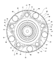
又、ハブ本体19の軸方向外端寄り部分に設けられた回転側フランジ22は、全体が円輪板状に構成されており、制動用回転部材の取付面となる軸方向外側面は、ハブ本体19の中心軸に対し直交する仮想平面上に存在する平坦面となっている。又、本例の回転側フランジ22は、径方向内端部に、軸方向厚さ寸法が全周に亙り変化しない根元部37が設けられているのに対し、径方向中間部に、軸方向厚さ寸法が円周方向に関して変化する肉厚変化部38が設けられている。この為、回転側フランジ22の軸方向内側面は、径方向内端部の根元部37では、ハブ15の中心軸に対し直交する仮想平面上に存在する平坦面となっているのに対し、径方向中間部に位置する肉厚変化部38では、円周方向に関する凹凸形状となっている。
Further, the
又、回転側フランジ22の径方向中間部(肉厚変化部38)には、複数(図示の例では5つ)の薄肉部39、39と、これら各薄肉部39、39よりも軸方向厚さ寸法が大きく且つ軸方向内側に突出(膨出)すると共に放射方向に伸長した複数(図示の例では5つ)の厚肉部40、40とが、円周方向に関して交互に設けられている。図示の例の場合、薄肉部39、39(厚肉部40、40)の円周方向に関する位相は72度ずつ等間隔にずれている。又、薄肉部39、39は、厚肉部40、40よりも径方向外方に僅かに延出する状態で設けられており、円周方向に隣り合う薄肉部39、39同士は、これら薄肉部39、39の一部である薄肉連続部41によって、厚肉部40、40の径方向外側で円周方向に連続している。従って、回転側フランジ22の径方向外端部には、薄肉部39(及び薄肉連続部41)が全周に亙り連続する状態で設けられている。
Further, a plurality of (five in the illustrated example) thin-
又、厚肉部40の軸方向厚さ寸法Xは、根元部37の軸方向厚さ寸法とほぼ同じであり、薄肉部39の軸方向厚さ寸法Yのおよそ2〜6倍程度(図示の例では4倍)に設定されている。尚、薄肉部39の軸方向厚さ寸法Yは、回転側フランジ22の円周方向に関して厚肉部40に隣接する部分と、径方向に関して厚肉部40の外側に位置する部分(薄肉連続部41)とで、互いに同じである。
Further, the axial thickness dimension X of the
回転側フランジ22の円周方向等間隔複数箇所(図示の例では5箇所)で、且つ、円周方向に関して厚肉部40、40とそれぞれ整合する部分のうち、これら厚肉部40、40の円周方向中央に位置する部分に、軸方向に貫通する状態で、取付孔42、42を設けている。本例の場合には、取付孔42を、軸方向外側の大径孔43と、軸方向内側の雌ねじ孔44との2種類の孔から構成している。別な言い方をすれば、厚肉部40の軸方向外側面から軸方向中間部に亙る範囲に大径孔43を形成し、厚肉部40の軸方向内側面から軸方向中間部に亙る範囲に雌ねじ孔44を形成している。又、軸方向外側の大径孔43と軸方向内側の雌ねじ孔44とは同軸上に配置されている。
Of the plurality of circumferentially equally spaced portions of the rotary side flange 22 (five in the illustrated example) and of the portions that respectively match the
大径孔43は、内周面が単一円筒面である円筒孔で、無ねじ状に構成されているのに対し、雌ねじ孔44は、内周面に雌ねじが形成されている。又、大径孔43の内径寸法は、雌ねじ孔44の内径寸法(雌ねじの歯底円の直径寸法)よりも大きく設定されており、軸方向に亙り変化しない。特に本例の場合には、この様な大径孔43の軸方向長さ寸法Aを、薄肉部39(薄肉連続部41)の軸方向厚さ寸法Yよりも大きく設定している(A>Y)。これにより、大径孔43と雌ねじ孔44との境界位置を、厚肉部40のうちで薄肉連続部41と径方向に重畳した重畳部45aではなく、厚肉部40のうちで薄肉連続部41と径方向に重畳していない非重畳部45bに位置させている。この為、雌ねじ孔44は、厚肉部40のうちの非重畳部45bにのみ形成されており、重畳部45aには形成されていない。
The large-
又、非重畳部45bの外周側面(外径面)は、取付孔42(雌ねじ孔44)と同心の部分円筒形状であり、非重畳部45bの外周側面と雌ねじ孔44の内周面との間の肉厚は、回転側フランジ22の径方向に関して雌ねじ孔44の外側に位置する部分で、円周方向及び軸方向に関してほぼ一定である。これに対し、回転側フランジ22の径方向に関して雌ねじ孔44の内側に位置する部分のうち、凹部48の内周面と雌ねじ孔44の内周面との間部分の肉厚は、円周方向に関して変化するが、軸方向に関してほぼ一定である。但し、凹部48の内周面と雌ねじ孔44の内周面との間の肉厚は、非重畳部45bの外周側面と雌ねじ孔44の内周面との間の肉厚よりも十分に大きいので、回転側フランジ22の径方向に関して雌ねじ孔44の内側に位置する部分の肉厚変化は、雌ねじ孔44を形成する部分(範囲)の剛性変化に殆ど影響を与える事はない。
Further, the outer peripheral side surface (outer diameter surface) of the
上述した様な取付孔42を形成するには、例えば、先ず、回転側フランジ22のうち、円周方向に関して厚肉部40と整合する部分に、大径孔43を、軸方向外側から軸方向内側に向けて、その奥端部が非重畳部45bにまで達する様に形成する。次いで、この大径孔43と同軸上に軸方向に貫通する状態で下孔を形成する。その後、下孔にタップで雌ねじを形成する事により、雌ねじ孔44を形成する。尚、タッピングドリルを用いて下孔の形成と雌ねじ孔44の形成を同時に行う事もできる。本例の場合には、この様にして、軸方向外側に大径孔43が設けられると共に、軸方向内側に雌ねじ孔44が設けられた、本例の取付孔42を形成する。
In order to form the mounting
そして、本例の場合にも、ホイール及び制動用回転部材にそれぞれ形成された通孔内に、ボルトを挿通した後、ボルトの先端部に形成された雄ねじを、取付孔42を構成する雌ねじ孔44に螺合させる。これにより、回転側フランジ22の軸方向外側面に、制動用回転部材及びホイールを固定する。
Also in the case of this example, after the bolt is inserted into the through holes formed in the wheel and the braking rotary member respectively, the male screw formed at the tip of the bolt is inserted into the female screw hole forming the mounting
又、車輪支持用転がり軸受ユニット1aの軽量化、又は、図示しない足回り部品の取り付け若しくは取り外しに使用する工具を挿入する為に、回転側フランジ22の円周方向等間隔複数箇所(5箇所)で、且つ、円周方向に関して薄肉部39、39とそれぞれ整合する部分に、軸方向に貫通する状態で、円形状の透孔46、46を設けている。これら各透孔46、46は、厚肉部40、40に設けられた取付孔42、42(大径孔43)よりも大きな内径寸法を有している。又、回転側フランジ22のうち、円周方向に関して薄肉部39、39と整合する部分で、且つ、円周方向に関して透孔46、46から外れた部分には、回転側フランジ22から制動用回転部材を取り外すのに利用する押しボルトを螺合させる為のねじ孔47、47を設けている。
Further, in order to reduce the weight of the wheel-supporting
以上の様な構成を有する本例の場合には、車輪を構成するホイールや制動用回転部材を固定する為に利用する回転側フランジ22の雌ねじ孔44の精度を十分に確保できる。
即ち、本例の場合には、厚肉部40を軸方向に貫通する状態で設けた取付孔42を、軸方向外側の大径孔43と軸方向内側の雌ねじ孔44とから構成し、更にこの大径孔43の軸方向長さ寸法Aを、薄肉部39(薄肉連続部41)の軸方向厚さ寸法Yよりも大きくしている。この為、本例の場合には、回転側フランジ22の径方向に関して雌ねじ孔44の外側に存在する部分の厚さ寸法を一定にできる。この為、厚肉部40のうちで、雌ねじ孔44を形成する部分(範囲)の剛性を、軸方向に関して一定にできる。従って、雌ねじ孔44を穿孔加工により形成する際に、この雌ねじ孔44が途中で折れ曲がったり、雌ねじ孔44の内径寸法が途中で変化したりする事を防止できる。この結果、本例の場合には、雌ねじ孔44の精度(形状精度及び寸法精度)を十分に確保できる。これにより、雌ねじ孔の精度が不十分である事に起因して生じる、ボルトの折れ曲がりや螺合部でのフレッチング摩耗等の前述した各種の問題の発生を有効に防止できる。
In the case of the present example having the above-described configuration, it is possible to sufficiently secure the accuracy of the
That is, in the case of this example, the mounting
[実施の形態の第2例]
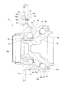
本発明の実施の形態の第2例に就いて、図3を参照しつつ説明する。本例の車輪支持用転がり軸受ユニット1bは、前述した従来構造の場合と同様に、外輪回転型で、静止側軌道輪である内径側軌道輪2aと、回転側軌道輪である外径側軌道輪3aと、それぞれが転動体である玉4a、4aとを備えている。
[Second Example of Embodiment]
A second example of the embodiment of the present invention will be described with reference to FIG. The wheel supporting
内径側軌道輪2aは、外周面に複列の内輪軌道5c、5dを有すると共に、内周面の軸方向内端部に、内径側軌道輪2aを懸架装置に支持固定する為の図示しない静止側フランジを有している。この様な内径側軌道輪2aは、主部49と、主部49の軸方向外端部に外嵌固定した内輪素子50とを、主部49の軸方向外端部に形成したかしめ部51により結合する事により構成されている。これら主部49及び内輪素子50は、それぞれ焼き入れ硬化可能な鉄系合金製であり、このうちの内輪素子50の外周面に、外側列の内輪軌道5cを形成しており、主部49の軸方向中間部外周面に内側列の内輪軌道5dを形成している。又、これら両内輪軌道5c、5dのうち、内側列の内輪軌道5dの外径寸法は、外側列の内輪軌道5cの外径寸法よりも大きくなっている。
The inner diameter
外径側軌道輪3aは、内周面に複列の外輪軌道7c、7dを有すると共に、外周面に車輪を支持固定する為の外向フランジ状の回転側フランジ8aを有している。この様な外径側軌道輪3aは、中炭素鋼等の焼き入れ硬化可能な鉄系合金製であり、内径側軌道輪2aの周囲に、この内径側軌道輪2aと同心に配置されている。外径側軌道輪3aの内周面に形成された外輪軌道7c、7dは、内側列の外輪軌道7dの内径寸法が、外側列の外輪軌道7cの内径寸法よりも大きくなっている。
The outer diameter
玉4a、4aは、内輪軌道5c、5dと外輪軌道7c、7dとの間に、両列毎にそれぞれ複数個ずつ、それぞれ保持器52a、52bに保持された状態で、転動自在に設けられている。又、内側列の玉4aのピッチ円直径は、外側列の玉4aのピッチ円直径よりも大きくなっている。
A plurality of
又、外径側軌道輪3aの内周面と内径側軌道輪2aの外周面との間に存在する、内部空間(転動体設置空間)26aの軸方向両端開口を、シールリング27a及びカバー28aにより塞いでいる。即ち、内部空間26aの軸方向内端開口部を、組み合わせ型等のシールリング27aにより塞いでいる。これに対し、内部空間26aの軸方向外端開口部は、径方向内側が軸方向に貫通していない内径側軌道輪2aの軸方向外側面と共に、外径側軌道輪3aの軸方向外端部に固定したカバー28aにより塞いでいる。
In addition, the
そして、本例の場合にも、外径側軌道輪3aに設けられた回転側フランジ8aを、複数の薄肉部9aと、これら各薄肉部9aよりも軸方向厚さ寸法が大きく且つ軸方向内側に突出(膨出)すると共に放射方向に伸長した複数の厚肉部10aとを、円周方向に関して交互に配置する事により構成している。又、薄肉部9aは、厚肉部10aよりも径方向外方に延出する状態で設けられており、円周方向に隣り合う薄肉部9a同士は、これら薄肉部9aの一部である薄肉連続部11aによって、厚肉部10aの径方向外側で円周方向に連続している。又、厚肉部10aの軸方向厚さ寸法Xは、薄肉部9a(薄肉連続部11a)の軸方向厚さ寸法Yのおよそ2〜6倍程度(図示の例では2.5倍)に設定されている。
Even in the case of this embodiment, the outer diameter side of the
又、回転側フランジ8aの円周方向等間隔複数箇所で、且つ、円周方向に関して厚肉部10aとそれぞれ整合する部分に、軸方向に貫通する状態で、取付孔42aを設けている。そして本例の場合にも、この取付孔42aを、軸方向外側の大径孔43aと、軸方向内側の雌ねじ孔44aとから構成している。
Further, mounting
特に本例の場合には、大径孔43aの軸方向長さ寸法Aを、薄肉部9aの軸方向厚さ寸法Yよりも大きく設定している。これにより、大径孔43aと雌ねじ孔44aとの境界位置を、厚肉部10aのうちで薄肉連続部11aと径方向に重畳した重畳部13cではなく、厚肉部10aのうちで薄肉連続部11aと径方向に重畳していない非重畳部13dに位置させている。この為、雌ねじ孔44aは、厚肉部10aのうちの非重畳部13dにのみ形成されており、重畳部13cには形成されていない。
Particularly in the case of this example, the axial length dimension A of the
以上の様な構成を有する本例の場合にも、前述した実施の形態の第1例の場合と同様に、雌ねじ孔44aを穿孔加工により形成する際に、この雌ねじ孔44aが途中で折れ曲がったり、雌ねじ孔44aの内径寸法が途中で変化したりする事を防止できる。従って、雌ねじ孔44aの精度(形状精度及び寸法精度)を十分に確保できる。
その他の構成及び作用効果に就いては、前記実施の形態の第1例の場合と同様である。
Also in the case of this example having the above-described configuration, as in the case of the first example of the above-described embodiment, when the
Other configurations and operational effects are the same as in the case of the first example of the above-described embodiment.
本発明は、実施の形態の各例に示した様に、従動輪用の車輪支持用転がり軸受ユニットだけでなく、駆動輪用の車輪支持用転がり軸受ユニットにも適用する事ができる。又、本発明は、前述した実施の形態の各例の構造を適宜組み合わせて実施する事もできる。 The present invention can be applied not only to the wheel supporting rolling bearing unit for the driven wheels but also to the wheel supporting rolling bearing unit for the driving wheels as shown in each of the embodiments. Further, the present invention can be implemented by appropriately combining the structures of the respective examples of the above-described embodiments.
1、1a、1b 車輪支持用転がり軸受ユニット
2、2a 内径側軌道輪
3、3a 外径側軌道輪
4、4a 玉
5a〜5d 内輪軌道
6 静止側フランジ
7a〜7d 外輪軌道
8、8a 回転側フランジ
9、9a 薄肉部
10、10a 厚肉部
11、11a 薄肉連続部
12 雌ねじ孔
13a、13c 重畳部
13b、13d 非重畳部
14 外輪
15 ハブ
16 玉
17a、17b 外輪軌道
18 静止側フランジ
18a ねじ孔
19 ハブ本体
20 内輪
21a、21b 内輪軌道
22 回転側フランジ
23 小径段部
24 かしめ部
25a、25b 保持器
26、26a 内部空間
27 シールリング
28 カバー
29 芯金
30 シール材
31a〜31d シールリップ
32 支持筒部
33 底板部
34 シール材
35 エンコーダ
36 支持環
37 根元部
38 肉厚変化部
39 薄肉部
40 厚肉部
41 薄肉連続部
42、42a 取付孔
43、43a 大径孔
44、44a 雌ねじ孔
45a 重畳部
45b 非重畳部
46 透孔
47 ねじ孔
48 凹部
49 主部
50 内輪素子
51 かしめ部
52a、52b 保持器
1, 1a, 1b Wheel support rolling
Claims (1)
周面に回転側軌道を有すると共に、車輪を固定する為の外向フランジ状の回転側フランジを有し、使用時に回転する回転側軌道輪と、
前記静止側軌道と前記回転側軌道との間に転動自在に設けられた複数個の転動体と、
を備え、
前記回転側フランジは、全体が板状に構成され、複数の薄肉部と、これら各薄肉部よりも軸方向厚さ寸法が大きく且つ軸方向内側に突出した複数の厚肉部とが、円周方向に関して交互に設けられており、円周方向に隣り合う薄肉部同士が前記各厚肉部の径方向外側で連続しており、
円周方向に関して前記各厚肉部と整合する部分に、これら各厚肉部を軸方向に貫通する状態で、軸方向内側の雌ねじ孔と、この雌ねじ孔よりも内径寸法が大きく且つ無ねじ状である軸方向外側の大径孔とから構成される取付孔が設けられており、この大径孔の軸方向長さ寸法が前記各薄肉部の軸方向厚さ寸法よりも大きい
車輪支持用転がり軸受ユニット。 A stationary raceway ring that has a stationary side raceway on the circumferential surface and is not supported by the suspension device and is not rotated during use.
Having a rotating side raceway on the circumferential surface, and having a rotating side flange in the form of an outward flange for fixing the wheel, and a rotating side raceway wheel that rotates during use,
A plurality of rolling elements provided rotatably between the stationary side track and the rotating side track,
Equipped with
The rotation-side flange is formed in a plate shape as a whole, and has a plurality of thin-walled portions and a plurality of thick-walled portions that have axial thicknesses larger than the thin-walled portions and project inward in the axial direction. Are alternately provided with respect to the direction, adjacent to each other in the circumferential direction, the thin portions are continuous on the outer side in the radial direction of the thick portions,
A female screw hole on the inner side in the axial direction and an inner diameter larger than the female screw hole and non-threaded in a portion that matches each thick portion in the circumferential direction with each thick portion axially penetrating. Is provided with a large-diameter hole on the outside in the axial direction, and the axial length dimension of the large-diameter hole is larger than the axial thickness dimension of each thin-walled portion. Bearing unit.
Priority Applications (3)
| Application Number | Priority Date | Filing Date | Title |
|---|---|---|---|
| JP2016211394A JP6705363B2 (en) | 2016-10-28 | 2016-10-28 | Rolling bearing unit for wheel support |
| DE202017106535.9U DE202017106535U1 (en) | 2016-10-28 | 2017-10-27 | Rolling bearing unit for wheel bearing |
| CN201721413506.0U CN207634514U (en) | 2016-10-28 | 2017-10-30 | Wheel support roller bearing unit |
Applications Claiming Priority (1)
| Application Number | Priority Date | Filing Date | Title |
|---|---|---|---|
| JP2016211394A JP6705363B2 (en) | 2016-10-28 | 2016-10-28 | Rolling bearing unit for wheel support |
Publications (3)
| Publication Number | Publication Date |
|---|---|
| JP2018071644A JP2018071644A (en) | 2018-05-10 |
| JP2018071644A5 JP2018071644A5 (en) | 2019-06-20 |
| JP6705363B2 true JP6705363B2 (en) | 2020-06-03 |
Family
ID=60579624
Family Applications (1)
| Application Number | Title | Priority Date | Filing Date |
|---|---|---|---|
| JP2016211394A Active JP6705363B2 (en) | 2016-10-28 | 2016-10-28 | Rolling bearing unit for wheel support |
Country Status (3)
| Country | Link |
|---|---|
| JP (1) | JP6705363B2 (en) |
| CN (1) | CN207634514U (en) |
| DE (1) | DE202017106535U1 (en) |
Families Citing this family (5)
| Publication number | Priority date | Publication date | Assignee | Title |
|---|---|---|---|---|
| JP6760149B2 (en) * | 2016-08-30 | 2020-09-23 | 日本精工株式会社 | Rolling bearing unit for wheel support |
| US11731456B2 (en) * | 2019-05-24 | 2023-08-22 | Aktiebolaget Skf | Wheel hub bearing with radial stiffening |
| IT201900013584A1 (en) * | 2019-08-01 | 2021-02-01 | Skf Ab | FLANGED INTERNAL RING FOR WHEEL HUB BEARINGS |
| JP2023011295A (en) * | 2021-07-12 | 2023-01-24 | Ntn株式会社 | Vehicle wheel bearing device |
| CN113819213A (en) * | 2021-09-22 | 2021-12-21 | 珠海格力电器股份有限公司 | Harmonic reducer ware flexbile gear subassembly and harmonic reducer ware |
Family Cites Families (5)
| Publication number | Priority date | Publication date | Assignee | Title |
|---|---|---|---|---|
| JP5641705B2 (en) * | 2009-04-02 | 2014-12-17 | Ntn株式会社 | Wheel bearing device |
| JP2012051393A (en) | 2010-08-31 | 2012-03-15 | Nsk Ltd | Rolling bearing unit for supporting wheel |
| JP2013067323A (en) * | 2011-09-26 | 2013-04-18 | Jtekt Corp | Bearing device for axle |
| JP6007655B2 (en) * | 2012-08-06 | 2016-10-12 | 株式会社ジェイテクト | Wheel bearing device |
| JP6366233B2 (en) | 2013-07-11 | 2018-08-01 | Ntn株式会社 | Wheel bearing device |
-
2016
- 2016-10-28 JP JP2016211394A patent/JP6705363B2/en active Active
-
2017
- 2017-10-27 DE DE202017106535.9U patent/DE202017106535U1/en active Active
- 2017-10-30 CN CN201721413506.0U patent/CN207634514U/en active Active
Also Published As
| Publication number | Publication date |
|---|---|
| DE202017106535U1 (en) | 2017-11-17 |
| JP2018071644A (en) | 2018-05-10 |
| CN207634514U (en) | 2018-07-20 |
Similar Documents
| Publication | Publication Date | Title |
|---|---|---|
| JP6705363B2 (en) | Rolling bearing unit for wheel support | |
| JP2014126106A (en) | Rolling bearing unit for supporting wheel | |
| JP4345988B2 (en) | Wheel bearing device | |
| US10598226B2 (en) | Bearing device for vehicle wheel | |
| JP2017190865A (en) | Hub unit bearing | |
| JP6610441B2 (en) | Rolling bearing unit for wheel support | |
| JP2014013073A (en) | Wheel bearing device | |
| JP5045725B2 (en) | Rolling bearing unit with rotational speed detector | |
| JP2007162831A (en) | Hub unit for driven wheel | |
| JP2016109183A (en) | Outer ring for rolling bearing unit, and rolling bearing unit for supporting wheel | |
| JP2006275200A (en) | Cover of rolling bearing device and rolling bearing device using this cover | |
| JP2008110659A (en) | Rolling bearing device for wheel | |
| JP4419638B2 (en) | Rolling bearing unit with rotational speed detector | |
| JP2018034775A (en) | Rolling bearing unit for supporting wheel | |
| WO2017179400A1 (en) | Hub unit bearing | |
| JP4260055B2 (en) | Wheel bearing device | |
| JP2008014471A (en) | Rolling bearing device with sensor | |
| JP2022097522A (en) | Hub unit bearing manufacturing method | |
| JP2019035421A (en) | Hub unit bearing with combination seal ring | |
| JP4245249B2 (en) | Bearing device | |
| JP6968044B2 (en) | Bearing device for wheels | |
| WO2017033653A1 (en) | Rolling bearing unit for wheel support | |
| JP6744724B2 (en) | Wheel bearing device | |
| JP2019085018A (en) | Hub unit bearing and hub unit bearing with braking rotating body | |
| JP2022128123A (en) | Bearing device for wheel |
Legal Events
| Date | Code | Title | Description |
|---|---|---|---|
| A521 | Written amendment |
Free format text: JAPANESE INTERMEDIATE CODE: A523 Effective date: 20190516 |
|
| A621 | Written request for application examination |
Free format text: JAPANESE INTERMEDIATE CODE: A621 Effective date: 20190516 |
|
| TRDD | Decision of grant or rejection written | ||
| A01 | Written decision to grant a patent or to grant a registration (utility model) |
Free format text: JAPANESE INTERMEDIATE CODE: A01 Effective date: 20200414 |
|
| A61 | First payment of annual fees (during grant procedure) |
Free format text: JAPANESE INTERMEDIATE CODE: A61 Effective date: 20200427 |
|
| R150 | Certificate of patent or registration of utility model |
Ref document number: 6705363 Country of ref document: JP Free format text: JAPANESE INTERMEDIATE CODE: R150 |