JP6704247B2 - Pneumatic system operation control device and control method - Google Patents
Pneumatic system operation control device and control method Download PDFInfo
- Publication number
- JP6704247B2 JP6704247B2 JP2015252808A JP2015252808A JP6704247B2 JP 6704247 B2 JP6704247 B2 JP 6704247B2 JP 2015252808 A JP2015252808 A JP 2015252808A JP 2015252808 A JP2015252808 A JP 2015252808A JP 6704247 B2 JP6704247 B2 JP 6704247B2
- Authority
- JP
- Japan
- Prior art keywords
- set value
- value
- control set
- air
- piping network
- Prior art date
- Legal status (The legal status is an assumption and is not a legal conclusion. Google has not performed a legal analysis and makes no representation as to the accuracy of the status listed.)
- Active
Links
Images


Classifications
-
- F—MECHANICAL ENGINEERING; LIGHTING; HEATING; WEAPONS; BLASTING
- F04—POSITIVE - DISPLACEMENT MACHINES FOR LIQUIDS; PUMPS FOR LIQUIDS OR ELASTIC FLUIDS
- F04B—POSITIVE-DISPLACEMENT MACHINES FOR LIQUIDS; PUMPS
- F04B49/00—Control, e.g. of pump delivery, or pump pressure of, or safety measures for, machines, pumps, or pumping installations, not otherwise provided for, or of interest apart from, groups F04B1/00 - F04B47/00
- F04B49/06—Control using electricity
- F04B49/065—Control using electricity and making use of computers
-
- F—MECHANICAL ENGINEERING; LIGHTING; HEATING; WEAPONS; BLASTING
- F04—POSITIVE - DISPLACEMENT MACHINES FOR LIQUIDS; PUMPS FOR LIQUIDS OR ELASTIC FLUIDS
- F04B—POSITIVE-DISPLACEMENT MACHINES FOR LIQUIDS; PUMPS
- F04B49/00—Control, e.g. of pump delivery, or pump pressure of, or safety measures for, machines, pumps, or pumping installations, not otherwise provided for, or of interest apart from, groups F04B1/00 - F04B47/00
- F04B49/06—Control using electricity
-
- F—MECHANICAL ENGINEERING; LIGHTING; HEATING; WEAPONS; BLASTING
- F04—POSITIVE - DISPLACEMENT MACHINES FOR LIQUIDS; PUMPS FOR LIQUIDS OR ELASTIC FLUIDS
- F04B—POSITIVE-DISPLACEMENT MACHINES FOR LIQUIDS; PUMPS
- F04B49/00—Control, e.g. of pump delivery, or pump pressure of, or safety measures for, machines, pumps, or pumping installations, not otherwise provided for, or of interest apart from, groups F04B1/00 - F04B47/00
- F04B49/08—Regulating by delivery pressure
-
- F—MECHANICAL ENGINEERING; LIGHTING; HEATING; WEAPONS; BLASTING
- F04—POSITIVE - DISPLACEMENT MACHINES FOR LIQUIDS; PUMPS FOR LIQUIDS OR ELASTIC FLUIDS
- F04B—POSITIVE-DISPLACEMENT MACHINES FOR LIQUIDS; PUMPS
- F04B49/00—Control, e.g. of pump delivery, or pump pressure of, or safety measures for, machines, pumps, or pumping installations, not otherwise provided for, or of interest apart from, groups F04B1/00 - F04B47/00
- F04B49/10—Other safety measures
- F04B49/106—Responsive to pumped volume
-
- F—MECHANICAL ENGINEERING; LIGHTING; HEATING; WEAPONS; BLASTING
- F04—POSITIVE - DISPLACEMENT MACHINES FOR LIQUIDS; PUMPS FOR LIQUIDS OR ELASTIC FLUIDS
- F04B—POSITIVE-DISPLACEMENT MACHINES FOR LIQUIDS; PUMPS
- F04B2203/00—Motor parameters
- F04B2203/02—Motor parameters of rotating electric motors
- F04B2203/0209—Rotational speed
-
- F—MECHANICAL ENGINEERING; LIGHTING; HEATING; WEAPONS; BLASTING
- F04—POSITIVE - DISPLACEMENT MACHINES FOR LIQUIDS; PUMPS FOR LIQUIDS OR ELASTIC FLUIDS
- F04B—POSITIVE-DISPLACEMENT MACHINES FOR LIQUIDS; PUMPS
- F04B2205/00—Fluid parameters
- F04B2205/05—Pressure after the pump outlet
-
- F—MECHANICAL ENGINEERING; LIGHTING; HEATING; WEAPONS; BLASTING
- F04—POSITIVE - DISPLACEMENT MACHINES FOR LIQUIDS; PUMPS FOR LIQUIDS OR ELASTIC FLUIDS
- F04B—POSITIVE-DISPLACEMENT MACHINES FOR LIQUIDS; PUMPS
- F04B2205/00—Fluid parameters
- F04B2205/06—Pressure in a (hydraulic) circuit
-
- F—MECHANICAL ENGINEERING; LIGHTING; HEATING; WEAPONS; BLASTING
- F04—POSITIVE - DISPLACEMENT MACHINES FOR LIQUIDS; PUMPS FOR LIQUIDS OR ELASTIC FLUIDS
- F04B—POSITIVE-DISPLACEMENT MACHINES FOR LIQUIDS; PUMPS
- F04B2205/00—Fluid parameters
- F04B2205/09—Flow through the pump
-
- F—MECHANICAL ENGINEERING; LIGHTING; HEATING; WEAPONS; BLASTING
- F04—POSITIVE - DISPLACEMENT MACHINES FOR LIQUIDS; PUMPS FOR LIQUIDS OR ELASTIC FLUIDS
- F04B—POSITIVE-DISPLACEMENT MACHINES FOR LIQUIDS; PUMPS
- F04B2207/00—External parameters
- F04B2207/02—External pressure
-
- F—MECHANICAL ENGINEERING; LIGHTING; HEATING; WEAPONS; BLASTING
- F05—INDEXING SCHEMES RELATING TO ENGINES OR PUMPS IN VARIOUS SUBCLASSES OF CLASSES F01-F04
- F05B—INDEXING SCHEME RELATING TO WIND, SPRING, WEIGHT, INERTIA OR LIKE MOTORS, TO MACHINES OR ENGINES FOR LIQUIDS COVERED BY SUBCLASSES F03B, F03D AND F03G
- F05B2270/00—Control
- F05B2270/10—Purpose of the control system
- F05B2270/101—Purpose of the control system to control rotational speed (n)
-
- F—MECHANICAL ENGINEERING; LIGHTING; HEATING; WEAPONS; BLASTING
- F05—INDEXING SCHEMES RELATING TO ENGINES OR PUMPS IN VARIOUS SUBCLASSES OF CLASSES F01-F04
- F05B—INDEXING SCHEME RELATING TO WIND, SPRING, WEIGHT, INERTIA OR LIKE MOTORS, TO MACHINES OR ENGINES FOR LIQUIDS COVERED BY SUBCLASSES F03B, F03D AND F03G
- F05B2270/00—Control
- F05B2270/30—Control parameters, e.g. input parameters
- F05B2270/301—Pressure
- F05B2270/3013—Outlet
-
- F—MECHANICAL ENGINEERING; LIGHTING; HEATING; WEAPONS; BLASTING
- F05—INDEXING SCHEMES RELATING TO ENGINES OR PUMPS IN VARIOUS SUBCLASSES OF CLASSES F01-F04
- F05B—INDEXING SCHEME RELATING TO WIND, SPRING, WEIGHT, INERTIA OR LIKE MOTORS, TO MACHINES OR ENGINES FOR LIQUIDS COVERED BY SUBCLASSES F03B, F03D AND F03G
- F05B2270/00—Control
- F05B2270/30—Control parameters, e.g. input parameters
- F05B2270/327—Rotor or generator speeds
Description
本発明は、インバータ等の可変速装置で制御される空気圧縮機を備えた空圧システム運転制御装置および制御方法に関する The present invention relates to a pneumatic system operation control device and a control method including an air compressor controlled by a variable speed device such as an inverter.
近年、地球温暖化防止、省エネ法といった消費電力削減の流れのなかで、工場に対しても消費電力を削減することが求められている。大気中の空気を圧縮した圧縮空気は、身近に利用出来るため、空気工具、空気プレス、空気ブレーキ、スプレーガン等を駆動するための動力源として幅広く用いられている。以降、圧縮空気にて駆動する機器を総称して末端機器と呼ぶ。圧縮空気は空気圧縮機によって圧縮され、工場内に設けられた配管ネットワークを経由して、末端機器に供給される。空気圧縮機の消費電力は、工場全体の消費電力の20〜30%を占めるといわれており、工場の省エネルギー化のために空気圧縮機の消費電力を削減する必要がある。 In recent years, in the trend of reducing power consumption such as the prevention of global warming and the Energy Conservation Law, it is required for factories to reduce the power consumption. Compressed air obtained by compressing air in the atmosphere can be used in everyday life, and is widely used as a power source for driving air tools, air presses, air brakes, spray guns, and the like. Hereinafter, devices driven by compressed air are collectively referred to as end devices. The compressed air is compressed by an air compressor and supplied to the end equipment through a piping network provided in the factory. The power consumption of the air compressor is said to account for 20 to 30% of the power consumption of the entire factory, and it is necessary to reduce the power consumption of the air compressor in order to save energy in the factory.
空気圧縮機の消費電力削減のためには、できうるかぎり空気圧縮機の吐出圧力を低減することが望ましい。一方、末端機器を安定に動作させるためには、末端機器に供給する圧縮空気の圧力を所望の圧力以上とする必要がある。空気圧縮機で圧縮した圧縮空気を末端機器に供給する配管ネットワークの圧力損失は、空気圧縮機の吐出空気流量及び末端機器の消費空気流量の変化に応じて変化する。そのため、一般に、末端機器への供給圧力が初望の圧力以上となるように、配管ネットワークの最大圧力損失を見込んで、空気圧縮機の吐出圧力を設定する。これにより、末端機器では所望の圧力以上の圧縮空気を得ることができる。しかし、消費空気流量が少ない場合は、配管ネットワークの圧力損失が小さくなるにもかかわらず、空気圧縮機の吐出圧力が高く設定されたままであるため、必要以上に空気圧縮機を駆動することとなり、余分な電力を消費することとなる。 In order to reduce the power consumption of the air compressor, it is desirable to reduce the discharge pressure of the air compressor as much as possible. On the other hand, in order to operate the terminal device stably, it is necessary to set the pressure of the compressed air supplied to the terminal device to a desired pressure or higher. The pressure loss of the piping network that supplies the compressed air compressed by the air compressor to the terminal equipment changes according to the changes in the discharge air flow rate of the air compressor and the consumed air flow rate of the terminal equipment. Therefore, in general, the discharge pressure of the air compressor is set in consideration of the maximum pressure loss of the piping network so that the supply pressure to the terminal equipment is equal to or higher than the initially desired pressure. As a result, the end device can obtain compressed air having a pressure higher than the desired pressure. However, when the flow rate of consumed air is small, the discharge pressure of the air compressor remains set high even though the pressure loss of the piping network is small, so the air compressor is driven more than necessary, It consumes extra power.
そこで、これに対応するため、特許文献1では、末端機器への供給圧力と空気圧縮機の吐出圧力を計測し、末端機器での消費空気流量に応じて、末端機器への供給圧力が所望の圧力となるように、空気圧縮機を駆動する電動機の回転数を可変制御することで、空気圧縮機の消費電力を削減しつつ、所望の圧力以上の圧縮空気を末端機器に供給するための空気圧縮機運転制御装置が開示されている。
Therefore, in order to deal with this, in
また、特許文献2では、学習機能により過去の空気圧縮機の運転条件履歴を記憶し、現在の空気圧縮機消費電力、空気圧縮機吐出圧力、および末端機器供給圧力の計測値に対して、過去の運転条件履歴を参照として、空気圧縮機の消費電力を削減しつつ、所望の圧力以上の圧縮空気を末端機器に供給するための空気圧縮機の運転条件を決定する技術が開示されている。
In addition, in
特許文献1で開示されている空気圧縮機運転制御装置により、空気圧縮機の消費電力を削減しつつ、所望の圧力以上の圧縮空気を末端機器に供給することが可能である。一方、配管ネットワークを構成する配管の体積の影響により、空気圧縮機の吐出圧力の変化に対して、末端機器への供給圧力は遅れを伴って変化し、その遅れ時間は数十秒程度となる。空気圧縮機吐出圧力に対して、末端機器供給圧力が遅れて応答するため、一般に、末端機器供給圧力が一定圧力となるように空気圧縮機を制御した場合、末端機器への供給圧力は変動する。そこで、特許文献1で開示されている空気圧縮機運転制御装置では、供給圧力の変動を抑えるように、空気圧縮機を駆動する電動機の回転数をPID制御により制御している。しかしながら、配管の体積は空気圧縮機を設置する配管レイアウトの条件によって異なり、設置後も末端機器の追設等により配管レイアウトは変化する。すなわち、特許文献1で開示されている空気圧縮機運転制御装置では、配管レイアウトの設置状況に応じて、制御設定値を調整することは困難であり、供給圧力が変動する可能性があった。
With the air compressor operation control device disclosed in
また、特許文献2で開示されている技術でも、空気圧縮機の消費電力を削減しつつ、所望の圧力以上の圧縮空気を末端機器に供給することが可能である。しかしながら、特許文献2で開示されている技術では、利用者が事前に空気圧縮機の運転条件を入力することが必須であった。また、配管レイアウトが変更された場合には、学習した過去の運転条件履歴を初期化し、再度、利用者が空気圧縮機の運転条件を入力する必要があるという課題があった。
Further, even with the technique disclosed in
本発明は上記事情に鑑みなされたものであり、利用者が事前に空気圧縮機の運転条件を入力する必要がなく、配管レイアウトの設置状況に応じて、末端機器への供給圧力の変動を抑えながら、空気圧縮機の消費電力を削減しつつ、所望の圧力以上の圧縮空気を末端機器に供給するための空気圧縮機運転制御装置を提供することを目的とする。 The present invention has been made in view of the above circumstances, the user does not need to input the operating conditions of the air compressor in advance, and suppresses the fluctuation of the supply pressure to the terminal device according to the installation situation of the piping layout. However, it is an object of the present invention to provide an air compressor operation control device for supplying compressed air having a desired pressure or higher to a terminal device while reducing the power consumption of the air compressor.
上記目的を達成するために、本発明は、
空気圧縮機の吐出圧力計測値と、末端機器への供給圧力計測値より、前記末端機器への供給圧力が一定となるように、前記空気圧縮機の駆動用電動機の回転数を可変制御する空圧システム運転制御装置であって、前記吐出圧力計測値と、前記供給圧力計測値を記憶する計測値記憶部と、前記空気圧縮機から前記末端機器に圧縮空気を供給する経路である空気配管ネットワークを対象として、前記空気配管ネットワーク内の空気流れを計算するためのデータで構成される空気配管ネットワークモデルを入力する空気配管ネットワークモデル入力部と、前記空気配管ネットワークモデルを記憶する空気配管ネットワークモデル記憶部と前記吐出圧力計測値と、前記供給圧力計測値と、前記空気配管ネットワークモデルより、前記末端機器へ供給される空気流量を計算する末端機器流量計算部と、前記空気流量を記憶する末端機器流量記憶部と、前記空気圧縮機の前記駆動用電動機の回転数を可変制御するための制御設定値と、前記空気流量と、前記空気配管ネットワークモデルより、前記制御設定値の更新値を計算する制御設定値計算部と、前記更新値を記憶する制御設定値記憶部と、前記更新値より、前記空気圧縮機の前記駆動用電動機の回転数を可変制御するための制御設定値を更新するための指令値を作成する制御設定値更新指令値作成部とを備えたことを特徴とする。
In order to achieve the above object, the present invention provides
Based on the discharge pressure measurement value of the air compressor and the supply pressure measurement value to the terminal device, an empty space that variably controls the rotation speed of the driving motor of the air compressor so that the supply pressure to the terminal device becomes constant. A pressure system operation control device, which is a measurement value storage unit that stores the discharge pressure measurement value and the supply pressure measurement value, and an air piping network that is a path for supplying compressed air from the air compressor to the terminal device. And an air piping network model storage unit for storing the air piping network model, which inputs an air piping network model composed of data for calculating an air flow in the air piping network. Unit, the discharge pressure measurement value, the supply pressure measurement value, and the end device flow rate calculation unit that calculates the flow rate of the air supplied to the end device from the air piping network model, and the end device that stores the air flow rate. An update value of the control set value is calculated from a flow rate storage unit, a control set value for variably controlling the rotation speed of the drive motor of the air compressor, the air flow rate, and the air piping network model. A control set value calculation unit, a control set value storage unit that stores the updated value, and a control set value for variably controlling the rotation speed of the drive motor of the air compressor from the updated value. And a control set value update command value creation unit for creating the command value of.
本発明によれば、利用者が事前に空気圧縮機の運転条件を入力する必要がなく、配管レイアウトの設置状況に応じて、末端機器への供給圧力の変動を抑えながら、空気圧縮機の消費電力を削減しつつ、所望の圧力以上の圧縮空気を末端機器に供給できる。 According to the present invention, the user does not need to input the operating conditions of the air compressor in advance, and the fluctuation of the supply pressure to the terminal device is suppressed according to the installation situation of the piping layout, while the consumption of the air compressor is reduced. Compressed air at a desired pressure or higher can be supplied to the end device while reducing power consumption.
以下に図面を用いて本発明の実施の形態を説明する。 Embodiments of the present invention will be described below with reference to the drawings.
図1は実施例1に係る空圧システム運転制御装置の概略構成図である。 FIG. 1 is a schematic configuration diagram of the pneumatic system operation control device according to the first embodiment.
図1に示した空圧システム運転制御装置は、空気圧縮機ユニット1、空気配管ネットワーク7、末端機器8、末端機器部圧力センサー9、制御設定値更新部10を備えている。
The pneumatic system operation control device shown in FIG. 1 includes an
空気圧縮機ユニット1は、大気から吸込んだ空気Aを圧縮し圧縮空気を吐出する。空気圧縮機ユニット1は、空気圧縮機本体2、空気圧縮機吐出部圧力センサー3、制御装置4、可変速装置5、電動機6から構成される。以下では、空気圧縮機ユニット1の概略構成について説明する。
The
空気圧縮機本体2は、空気Aを吸込んで圧縮する。
The
空気圧縮機吐出部圧力センサー3は、空気圧縮機本体2から吐出する圧縮機空気の圧力を計測する。計測された圧力値は、制御装置4および制御設定値更新部10に出力される。
The air compressor discharge part pressure sensor 3 measures the pressure of the compressor air discharged from the
制御装置4は、空気圧縮機吐出部圧力センサー3の圧力計測値、末端機器部圧力センサー9の圧力計測値を入力として、末端機器8への圧縮機空気の供給圧力が要求圧力P0以上となるように、電動機6の回転数を制御し、電動機6に対する回転数指令値を計算、出力する。電動機6の回転数を制御する具体的な演算方法については、例えば、特許文献1「特開2010−24845号公報」に記載された方法により実現可能である。また、制御装置4は、電動機6の回転数を制御するための制御設定値D1の現在値を制御設定値更新部10に出力するとともに、制御設定値更新部10が出力する制御設定値更新指令値D2に基づき、制御設定値の現在値D1を更新する。
The control device 4 receives the pressure measurement value of the air compressor discharge part pressure sensor 3 and the pressure measurement value of the terminal device
可変速装置5は、回転数指令値を入力として電動機6を指定した回転数で回転させるために必要となる電力を出力する。
The
電動機6は空気圧縮機本体2と回転軸を介して結合しており、入力された電力をもとに回転し、空気圧縮機本体2を駆動させる。
The electric motor 6 is coupled to the
以上が空気圧縮機ユニット1の概略構成である。
The above is the schematic configuration of the
空気配管ネットワーク7は、空気層、フィルタ、ドライヤー、配管、エルボ、分岐、弁等の機器から構成され、空気圧縮機ユニット1から吐出した圧縮空気は空気配管ネットワーク7を介して、末端機器8に供給される。
The
末端機器8は、空気工具、空気プレス、空気ブレーキ、スプレーガン等、工場の製造工程で使用される機器であり、空気配管ネットワーク7を介して供給される圧縮空気を動力源として駆動する。
The
末端機器部圧力センサー9は、末端機器8に供給される圧縮機空気の圧力を計測する。計測された圧力値は、制御装置4および制御設定値更新部10に出力される。
The terminal
制御設定値更新部10は、空気圧縮機吐出部圧力センサー3の圧力計測値、末端機器部圧力センサー9の圧力計測値を入力として、制御設定値更新指令値を出力する。制御装置4は、上記の制御設定値更新指令値を入力として、制御設定値を更新する。
The control set
以下では、図2を用いて制御設定値更新部10の詳細について説明する。制御設定値更新部10は、計測値記憶部100、空気配管ネットワークモデル入力部101、空気配管ネットワークモデル記憶部102、末端機器流量計算部103、末端機器流量記憶部104、制御設定値計算部105、制御設定値記憶部106、制御設定値更新指令値作成部107から構成される。
Details of the control set
計測値記憶部100は、メモリやハードディスクで構成されており、空気圧縮機吐出部圧力センサー3および末端機器部圧力センサー9で取得した圧力計測値D3を格納する。
The measurement
空気配管ネットワークモデル入力部101では、空気配管ネットワーク7内の圧縮空気の流れを計算するために必要となるデータを入力し、空気配管ネットワークモデルD4を出力する。具体的には、空気配管ネットワーク7を構成する機器間の接続関係を定義するデータ、機器の属性(例えば、配管に対しては配管長さ、配管口径等)を定義するデータ、
および空気圧縮機ユニット1の吐出空気圧力を計算するためのデータである。
The air piping network
And data for calculating the discharge air pressure of the
空気配管ネットワークモデル記憶部102は、メモリやハードディスクで構成されており、空気配管ネットワークモデル入力部101が出力する空気配管ネットワークモデルD4を格納する。
The air piping network
末端機器流量計算部103では、圧力計測値D3、空気配管ネットワークモデルD4より、空気配管ネットワーク7内の空気流れを計算し、末端機器に供給される圧縮空気流量である末端機器流量D5を出力する。空気配管ネットワーク7内の空気流れを計算する具体的な計算手法については、例えば、文献「G.P. Greyvenstein(2002), An implicit method for the analysis of transient flows in pipe networks, International Journal for Numerical Methods in Engineering, vol. 53, issue 5, pp. 1127-1143」に記載された手法により実現可能である。
The terminal device flow
末端機器流量記憶部104は、メモリやハードディスクで構成されており末端機器流量計算部103が出力する末端機器流量D5を格納する。
The end device flow
制御設定値計算部105では、制御設定値D1、空気配管ネットワークモデルD4、末端機器流量D5より、末端機器への供給圧力の変動を抑制するように、制御設定値を計算し、制御設定値更新値D6として出力する。制御設定値更新値D6の具体的な計算方法については、図6、図7、図8を用いて後述する。
The control set
制御設定値記憶部106は、メモリやハードディスクで構成されており制御設定値計算部105が出力する制御設定値更新値D6を格納する。
The control set
制御設定値更新指令値作成部107は、制御設定値更新値D6を入力として、制御装置4の制御設定値D1を更新するための制御設定値更新指令値D2を出力する。
The control set value update command
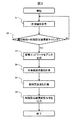
以上が、空圧システム運転制御装置の構成である。次に、制御設定値更新部10の処理の内容を詳細に説明する。図3は、実施例1に係る空圧システム運転制御装置における制御設定値更新の処理手順を示す。
The above is the configuration of the pneumatic system operation control device. Next, the contents of the processing of the control set
ステップS1(計測値取得過程)として、計測値記憶部100は、空気圧縮機吐出部圧力センサー3および末端機器部圧力センサー9で取得した圧力計測値D3をメモリやハードディスクに格納する。
As step S1 (measurement value acquisition process), the measurement
ステップS2(制御設定値タイミング判定過程)として、制御設定値更新部10は、現在時刻が、あらかじめ設定されている制御設定値更新タイミングと一致しているか否かを判定する。判定結果がYesならば、ステップS3(配管ネットワークモデル生成過程)に進み、Noならば、ステップS1の処理を継続する。ステップS1、S2の処理により、図4に示す、空気圧縮機吐出部の圧縮空気圧力、および末端機器8に供給される圧縮空気圧力の時系列データが得られる。
In step S2 (control set value timing determination process), the control set
ステップS3(配管ネットワークモデル生成過程)として、空気配管ネットワークモデル入力部101は、空気配管ネットワーク7内の圧縮空気の流れを計算するために必要となるデータを入力し、空気配管ネットワークモデルD4を出力する。空気配管ネットワークモデルD4は、空気配管ネットワークモデル記憶部102によりメモリやハードディスクに格納される。
In step S3 (piping network model generation process), the air piping network
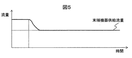
ステップS4(末端機器流量計算過程)として、末端機器流量計算部103は、圧力計測値D3、空気配管ネットワークモデルD4より、空気配管ネットワーク7内の空気流れを計算し、末端機器に供給される圧縮空気流量である末端機器流量D5を出力する。図5は、図4に示す、空気圧縮機吐出部の圧縮空気圧力、および末端機器8に供給される圧縮空気圧力の時系列データに対して、末端機器流量計算部103により出力される末端機器流量D5の例である。末端機器流量D5は、末端機器流量記憶部104によりメモリやハードディスクに格納される。
In step S4 (terminal device flow rate calculation process), the terminal device flow
ステップS5(制御設定値計算過程)として、制御設定値計算部105は、制御設定値D1、空気配管ネットワークモデルD4、末端機器流量D5より、末端機器への供給圧力の変動を抑制するように、制御設定値更新値D6を計算する。ステップS5の処理の詳細については、図6、図7、図8を用いて後述する。制御設定値更新値D6は、制御設定値記憶部106によりメモリやハードディスクに格納される。
As step S5 (control set value calculation process), the control set
ステップS6(制御設定値更新指令値出力過程)として、制御設定値更新指令値作成部107は、制御設定値更新値D6を入力として、制御装置4の制御設定値D1を更新するための制御設定値更新指令値D2を出力する。
In step S6 (control set value update command value output process), the control set value update command
次に、ステップS5(制御設定値計算過程)の処理の詳細について、図6、図7、図8を用いて説明する。図6に示すように、ステップS5はステップS51〜ステップS56の6つの処理過程を含む。 Next, details of the process of step S5 (control set value calculation process) will be described with reference to FIGS. 6, 7, and 8. As shown in FIG. 6, step S5 includes the six processing steps of steps S51 to S56.
ステップS51(制御設定値初期化過程)として、制御設定値計算部105は、制御設定値D1を制御設定値更新値D6に代入し、初期化する。例えば、制御装置4がPID制御により電動機6の回転数を制御する場合は、制御設定値D1は、比例ゲインKP、積分時間TI,微分時間TDの3つのパラメータとなり、制御設定値更新値D6にはこれら3つのパラメータの現在値が代入される。
As step S51 (control set value initialization process), the control set
ステップS52(配管ネットワーク空気流れ計算過程)として、制御設定値計算部105は、空気配管ネットワークモデルD4、末端機器流量D5、制御設定値更新値D6より、空気配管ネットワーク7内の空気流れを計算し、末端機器8に供給される圧縮空気圧力である末端器供給圧力計算値PCを出力する。
In step S52 (pipe network air flow calculation process), the control set
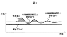
ステップS53(圧力偏差量計算過程)として、制御設定値計算部105は、末端機器8への供給圧力の変動量を評価する指標として、末端機器供給圧力設定値PSに対する末端器供給圧力計算値PCの偏差量Eを計算する。ここで、偏差量Eは、図7に示す図中の斜線で示す面積値であり、以下の式より計算される。
In step S53 (pressure deviation amount calculation process), the control setting
E=∫|PC−PS|dt・・・(式1)
また、末端機器供給圧力設定値PSに関しては、制御装置4における電動機6の回転数の制御により、末端機器供給圧力が要求圧力P0以上となるように、その値が設定される。空気配管ネットワーク7を構成する配管の体積の影響により、空気圧縮機吐出圧力に対して、末端機器供給圧力が遅れて応答する。そのため、末端機器供給圧力が一定圧力となるように空気圧縮機を制御した場合、末端機器供給圧力は変動する。そのため、図7に示すように、末端機器供給圧力設定値PSは要求圧力P0よりも高く設定される。
E=∫|PC-PS|dt (Equation 1)
Further, the terminal equipment supply pressure set value PS is set by controlling the rotation speed of the electric motor 6 in the control device 4 so that the terminal equipment supply pressure becomes equal to or higher than the required pressure P0. Due to the influence of the volume of the pipes forming the
ステップS54(制御設定値更新処理終了判定過程)として、制御設定値計算部105は、偏差量Eが閾値より大きいか否かを判定する。判定結果がYesならばステップS56(制御設定値格納過程)に進み、Noの場合は、ステップS55(制御設定値修正過程)へ進む。
In step S54 (control set value update process end determination process), the control set
ステップS55(制御設定値修正過程)として、制御設定値計算部105は、偏差量Eが減少するように、制御設定値更新値D6を修正する。制御設定値更新値D6を修正する具体的な計算方法としては、例えば、公知の最適化アルゴリズムである遺伝的アルゴリズム法、焼きなまし法等の手法により実現可能である。
In step S55 (control set value correction process), the control set
ステップS56(制御設定値格納過程)として、制御設定値計算部105は、制御設定値更新値D6を出力し、制御設定値記憶部106によりメモリやハードディスクに格納される。
In step S56 (control set value storage process), the control set
図8は、制御設定値D1に対する末端機器供給圧力と、制御設定値更新値D6に対する末端機器供給圧力を比較した図である。制御設定値計算部105は、末端機器供給圧力設定値PSに対する末端器供給圧力計算値PCの偏差量Eが閾値以下となるように、制御設定値更新値D6を修正するため、制御設定値更新値D6に対する末端機器供給圧力の変動量は、制御設定値D1に対する末端機器供給圧力の変動量よりも小さい結果となる。
FIG. 8 is a diagram comparing the terminal device supply pressure with respect to the control set value D1 and the terminal device supply pressure with respect to the control set value update value D6. Since the control set
以上が、ステップS5の処理の詳細に関する説明である。 The above is the description regarding the details of the processing in step S5.
実施例では、図3、図6に示した制御設定値更新の処理手順に従って、配管レイアウトの設置状況に応じて、末端機器への供給圧力の変動が小さくなるように、制御装置4における電動機6の回転数を制御するための制御設定値D1が更新される。また、利用者は、事前に空気圧縮機の運転条件を入力する必要はない。 In the embodiment, according to the processing procedure for updating the control set values shown in FIGS. 3 and 6, the electric motor 6 in the control device 4 is controlled so that the fluctuation of the supply pressure to the terminal equipment becomes small according to the installation situation of the piping layout. The control set value D1 for controlling the rotation speed of is updated. Further, the user does not need to input the operating condition of the air compressor in advance.
上述の通り、本実施形態では、利用者が事前に空気圧縮機の運転条件を入力する必要がなく、配管レイアウトの設置状況に応じて、末端機器への供給圧力の変動を抑えながら、空気圧縮機の消費電力を削減しつつ、所望の圧力以上の圧縮空気を末端機器に供給できる。 As described above, in the present embodiment, it is not necessary for the user to input the operating conditions of the air compressor in advance, and the air compression is suppressed while suppressing the fluctuation of the supply pressure to the terminal device according to the installation situation of the piping layout. It is possible to supply compressed air of a desired pressure or higher to the end device while reducing the power consumption of the machine.
図9は実施例2に係る制御設定値更新部10の概略構成図である。実施例1と同様の部分については同図において既出図面と同符号を付して説明を省略する。
FIG. 9 is a schematic configuration diagram of the control set
実施例1と相違する点は、制御設定値の更新処理において、末端機器供給圧力設定値も更新する点である。具体的には、本実施例における空圧システム運転制御装置は、制御設定値計算部105の代わりに、制御設定値計算部205を備える。
The difference from the first embodiment is that the end device supply pressure set value is also updated in the control set value updating process. Specifically, the pneumatic system operation control device in the present embodiment includes a control set
制御設定値計算部205では、制御設定値D1、空気配管ネットワークモデルD4、末端機器流量D5より、末端機器への供給圧力の変動を抑制しつつ、その供給圧力値が低くなるように、制御設定値と末端機器供給圧力設定値を計算し、制御設定値更新値D6に供給圧力設定値更新値PSaを加えて、制御設定値更新値D6aとして出力する。
The control set
以上が、実施例1と相違する点であり、その他の点は実施例1と同様である。 The above is the difference from the first embodiment, and other points are the same as the first embodiment.
次に、制御設定値更新部10の処理の内容を詳細に説明する。図10は、実施例2に係るステップS5(制御設定値計算過程)の処理の詳細手順を示す。実施例1と同様の部分については同図において既出図面と同符号を付して説明を省略する。
Next, the contents of the processing of the control set
本実施例の処理手順が実施例1の処理手順と相違する点は、ステップS55(制御設定値修正過程)の後に、S251の処理過程を含む点である。 The processing procedure of the present embodiment is different from the processing procedure of the first embodiment in that after the step S55 (control set value correction process), the process step of S251 is included.
ステップS251(供給圧力設定値更新過程)として、制御設定値計算部205は、末端機器供給圧力が要求圧力P0以上となる範囲内で、末端機器供給圧力設定値PSが最小となるよう値を更新する。具体的は、図11に示すように、末端器供給圧力計算値PCの最小値PCmin、要求圧力P0に対して、供給圧力設定値更新値PSaは、以下の式より計算される。
In step S251 (supply pressure set value update process), the control set
PSa=PS−(PCmin−P0)・・・(式2)
図12は、制御設定値D1に対する末端機器供給圧力と、制御設定値更新値D6aに対する末端機器供給圧力を比較した図である。制御設定値計算部205は、末端機器への供給圧力の変動を抑制する処理に加え、その供給圧力値が低くなるように末端機器供給圧力設定値PSを更新する。これにより、制御設定値更新値D6aに対する末端機器供給圧力値は、制御設定値D1に対する末端機器供給圧力値よりも低い値となる。末端機器供給圧力が低くなることにより、空気圧縮機の吐出圧力も低くすることができ、空気圧縮機の消費電力を削減することが可能である。
PSa=PS-(PCmin-P0) (Equation 2)
FIG. 12 is a diagram comparing the terminal device supply pressure with respect to the control set value D1 and the terminal device supply pressure with respect to the control set value update value D6a. The control set
以上が、本実施例の処理手順が実施例1と相違する点であり、その他の点は実施例1の処理手順と同様である。 The above is the point that the processing procedure of the present embodiment is different from that of the first embodiment, and other points are the same as the processing procedure of the first embodiment.
上述の通り、本実施例では実施例1で得られる各効果に加えて、供給圧力値が低くなるように供給圧力設定値を更新することで、空気圧縮機の消費電力を削減することができる。 As described above, in this embodiment, in addition to the effects obtained in the first embodiment, by updating the supply pressure set value so that the supply pressure value becomes low, the power consumption of the air compressor can be reduced. ..
図13は実施例3に係る制御設定値更新部10の概略構成図である。実施例3と同様の部分については同図において既出図面と同符号を付して説明を省略する。
FIG. 13 is a schematic configuration diagram of the control set
実施例2と相違する点は、制御設定値更新前と更新後の条件に対して、末端機器供給圧力の変動、および空気圧縮機消費電力値を表示装置に表示する点である。具体的には、本実施の形態における空圧システム運転制御装置は、制御設定値計算部205、制御設定値記憶部106の代わりに、制御設定値計算部305、制御設定値記憶部306、表示部301を備える。
The difference from the second embodiment is that the fluctuation of the terminal equipment supply pressure and the air compressor power consumption value are displayed on the display device for the conditions before and after the update of the control set value. Specifically, in the pneumatic system operation control device according to the present embodiment, instead of the control set
制御設定値計算部305では、制御設定値D1、空気配管ネットワークモデルD4、末端機器流量D5より、末端機器への供給圧力の変動を抑制しつつ、その供給圧力値が低くなるように、制御設定値と末端機器供給圧力設定値を計算し、制御設定値更新値D6aとして出力する。さらに、制御設定値D1と制御設定値更新値D6aに対する配管ネットワーク流れ計算結果D7を出力する。
In the control set
制御設定値記憶部306は、メモリやハードディスクで構成されており制御設定値計算部305が出力する制御設定値更新値D6aと配管ネットワーク流れ計算結果D7を格納する。
The control set
表示部301は、表示装置(ディスプレイ)を備えており、配管ネットワーク流れ計算結果D7を用いて、制御設定値D1と制御設定値更新値D6aに対する末端機器供給圧力の変動、および空気圧縮機消費電力値を表示装置に表示する。
The
以上が、実施例2と相違する点であり、その他の点は実施例2と同様である。 The above is the difference from the second embodiment, and other points are the same as the second embodiment.
次に、制御設定値更新部10の処理の内容を詳細に説明する。図14は、実施例3に係るステップS5(制御設定値計算過程)の処理の詳細手順を示す。実施例2と同様の部分については同図において既出図面と同符号を付して説明を省略する。
Next, the contents of the processing of the control set
本実施の形態の処理手順が実施例2の処理手順と相違する点は、ステップS56の代わりに、S351、S352の処理過程を含む点である。 The processing procedure of the present embodiment is different from the processing procedure of Example 2 in that it includes the processing steps of S351 and S352 instead of step S56.
ステップS351(制御設定値、配管流れ計算結果格納過程)として、制御設定値計算部305は、制御設定値更新値D6aと配管ネットワーク流れ計算結果D7を出力し、制御設定値記憶部306によりメモリやハードディスクに格納される。
In step S351 (control set value/pipe flow calculation result storage process), the control set
ステップS352(圧力変動、消費電力表示過程)として、表示部301は、配管ネットワーク流れ計算結果D7を用いて、制御設定値D1と制御設定値更新値D6aに対する末端機器供給圧力の変動、および空気圧縮機消費電力値を表示装置に表示する。図15は、設定値D1と制御設定値更新値D6aに対する末端機器供給圧力の変動、および空気圧縮機消費電力値の表示例を示している。表示画面上側には、制御設定値D1に対する末端機器供給圧力の変動と空気圧縮機消費電力値が表示されている。表示画面下側には、制御設定値更新値D6aに対する末端機器供給圧力の変動と空気圧縮機消費電力値が表示されている。図15に示した表示例の他に、末端機器供給圧力の変動のみ、あるいは空気圧縮機消費電力値のみが表示されていてもよい。
In step S352 (pressure fluctuation and power consumption display process), the
以上が、本実施例の処理手順が実施例2と相違する点であり、その他の点は実施例2の処理手順と同様である。 The above is the point that the processing procedure of the present embodiment is different from that of the second embodiment, and other points are the same as the processing procedure of the second embodiment.
上述の通り、実施例2で得られる各効果に加えて、制御設定値更新前と更新後の条件に対して、末端機器供給圧力の変動、および空気圧縮機消費電力値を表示装置に表示することで、空圧システムの設備管理者が末端機器における圧力変動の抑制効果、空気圧縮機の消費電力削減効果を確認できる
本発明における上記実施例では、配管ネットワーク内に流れる流体が、空気圧縮機により圧縮された圧縮空気である形態について説明したが、本発明はこれに限定されるものではなく、配管ネットワーク内を蒸気、水、空調用空気、油圧用の油等が流れる形態としてよい。
As described above, in addition to the effects obtained in the second embodiment, the fluctuation of the terminal device supply pressure and the air compressor power consumption value are displayed on the display device under the conditions before and after the update of the control set value. By doing so, the equipment manager of the pneumatic system can confirm the effect of suppressing the pressure fluctuation in the end equipment and the effect of reducing the power consumption of the air compressor. In the above embodiment of the present invention, the fluid flowing in the piping network is the air compressor. However, the present invention is not limited to this, and steam, water, air for air conditioning, oil for hydraulic pressure, or the like may flow in the piping network.
1 空気圧縮機ユニット
2 空気圧縮機本体
3 空気圧縮機吐出部圧力センサー
4 制御装置
5 可変速装置
6 電動機
7 空気配管ネットワーク
8 末端機器
9 末端機器部圧力センサー
10 制御設定値更新部
100 計測値記憶部
101 空気配管ネットワークモデル入力部
102 空気配管ネットワークモデル記憶部
103 末端機器流量計算部
104 末端機器流量記憶部
105、205、305 制御設定値計算部
106、306 制御設定値記憶部
107 制御設定値更新指令値作成部
301 表示部
1
Claims (6)
前記吐出圧力計測値と、前記供給圧力計測値を記憶する計測値記憶部と、
前記空気圧縮機から前記末端機器に圧縮空気を供給する経路である空気配管ネットワークを対象として、前記空気配管ネットワーク内の空気流れを計算するためのデータで構成される空気配管ネットワークモデルを入力する空気配管ネットワークモデル入力部と、
前記空気配管ネットワークモデルを記憶する空気配管ネットワークモデル記憶部と
前記吐出圧力計測値と、前記供給圧力計測値と、前記空気配管ネットワークモデルより、前記末端機器へ供給される空気流量を計算する末端機器流量計算部と、
前記空気流量を記憶する末端機器流量記憶部と、
前記空気圧縮機の前記駆動用電動機の回転数を可変制御するための制御設定値と、前記空気流量と、前記空気配管ネットワークモデルより、前記制御設定値の更新値を計算する制御設定値計算部と、
前記更新値を記憶する制御設定値記憶部と、
前記更新値より、前記空気圧縮機の前記駆動用電動機の回転数を可変制御するための制御設定値を更新するための指令値を作成する制御設定値更新指令値作成部と
を備えたことを特徴とする空圧システム運転制御装置。 Based on the discharge pressure measurement value of the air compressor and the supply pressure measurement value to the terminal device, an empty space for variably controlling the rotation speed of the driving motor of the air compressor so that the supply pressure to the terminal device becomes constant. A pressure system operation controller,
A discharge pressure measurement value, a measurement value storage unit that stores the supply pressure measurement value,
Air inputting an air piping network model composed of data for calculating an air flow in the air piping network for the air piping network which is a path for supplying compressed air from the air compressor to the terminal device Piping network model input section,
An air piping network model storage unit that stores the air piping network model, the discharge pressure measurement value, the supply pressure measurement value, and an end device that calculates an air flow rate to be supplied to the end device from the air piping network model. A flow rate calculation unit,
An end device flow rate storage unit that stores the air flow rate,
A control set value calculation unit for calculating an updated value of the control set value from the control set value for variably controlling the rotation speed of the drive motor of the air compressor, the air flow rate, and the air piping network model. When,
A control set value storage unit that stores the updated value,
And a control set value update command value creation unit that creates a command value for updating the control set value for variably controlling the rotation speed of the drive motor of the air compressor from the update value. Characteristic pneumatic system operation control device.
前記制御設定値計算部は、前記制御設定値の更新値と、前記末端機器への供給圧力設定値の更新値とを計算することを特徴とする空圧システム運転制御装置。 The pneumatic system operation control device according to claim 1,
The pneumatic system operation control device, wherein the control set value calculation unit calculates an updated value of the control set value and an updated value of the supply pressure set value to the terminal device .
前記制御設定値計算部は、前記制御設定値及び前記制御設定値の更新値に対する、前記空気配管ネットワークの内の空気流れ計算結果を出力し、
前記制御設定値記憶部は、前記空気流れ計算結果を記憶し、
前記空気流れ計算結果より、前記制御設定値及び前記制御設定値の更新値に対する、前記末端機器での圧力変動、あるいは前記空気圧縮機の消費電力を表示する表示部と
を備えたことを特徴とする空圧システム運転制御装置。 In the pneumatic system operation control device according to any one of claims 1 and 2 ,
The control set value calculation unit outputs an air flow calculation result in the air piping network for the control set value and the update value of the control set value ,
The control set value storage unit stores the air flow calculation result,
A display unit for displaying the pressure fluctuation in the terminal device or the power consumption of the air compressor with respect to the control set value and the updated value of the control set value based on the air flow calculation result. Pneumatic system operation control device.
前記吐出圧力計測値と、前記供給圧力計測値を記憶し、
前記空気圧縮機から前記末端機器に圧縮空気を供給する経路である空気配管ネットワークを対象として、前記空気配管ネットワーク内の空気流れを計算するためのデータで構成される空気配管ネットワークモデルを入力し、
前記空気配管ネットワークモデルを記憶し、
前記吐出圧力計測値と、前記供給圧力計測値と、前記空気配管ネットワークモデルより、前記末端機器へ供給される空気流量を計算し、
前記空気流量を記憶し、
前記空気圧縮機の前記駆動用電動機の回転数を可変制御するための制御設定値と、前記空気流量と、前記空気配管ネットワークモデルより、前記制御設定値の更新値を計算し、
前記更新値を記憶し、
前記更新値より、前記空気圧縮機の前記駆動用電動機の回転数を可変制御するための制御設定値を更新する
ことを特徴とする空圧システム運転制御方法。 Based on the discharge pressure measurement value of the air compressor and the supply pressure measurement value to the terminal device, an empty space that variably controls the rotation speed of the driving motor of the air compressor so that the supply pressure to the terminal device becomes constant. A pressure system operation control method,
The discharge pressure measurement value and the supply pressure measurement value are stored,
Targeting an air piping network that is a path for supplying compressed air from the air compressor to the terminal device, input an air piping network model composed of data for calculating an air flow in the air piping network,
Storing the air piping network model,
From the discharge pressure measurement value, the supply pressure measurement value, and the air piping network model, calculate the air flow rate to be supplied to the end device,
Storing the air flow rate,
A control set value for variably controlling the rotation speed of the driving electric motor of the air compressor, the air flow rate, and the air piping network model, calculate an update value of the control set value,
Storing the updated value,
A pneumatic system operation control method comprising: updating a control set value for variably controlling the rotation speed of the driving electric motor of the air compressor from the updated value.
前記制御設定値の更新値の計算は、前記制御設定値の更新値と、前記末端機器への供給圧力設定値の更新値とを計算することを特徴とする空圧システム運転制御方法。 The pneumatic system operation control method according to claim 4,
The pneumatic system operation control method, wherein the update value of the control set value is calculated by calculating the update value of the control set value and the update value of the supply pressure set value to the terminal device .
前記制御設定値及び前記制御設定値の更新値に対する、前記空気配管ネットワークの内の空気流れ計算結果を出力し、
前記更新値の記憶は、前記空気流れ計算結果を記憶し、
前記空気流れ計算結果より、前記制御設定値及び前記制御設定値の更新値に対する、前記末端機器での圧力変動、あるいは前記空気圧縮機の消費電力を表示する
ことを特徴とする空圧システム運転制御方法。 The pneumatic system operation control method according to any one of claims 4 and 5 ,
For the control set value and the updated value of the control set value, outputting the air flow calculation result in the air piping network,
The storage of the updated value stores the air flow calculation result,
Pneumatic system operation control characterized by displaying the pressure fluctuation in the terminal device or the power consumption of the air compressor with respect to the control set value and the updated value of the control set value from the air flow calculation result. Method.
Priority Applications (5)
| Application Number | Priority Date | Filing Date | Title |
|---|---|---|---|
| JP2015252808A JP6704247B2 (en) | 2015-12-25 | 2015-12-25 | Pneumatic system operation control device and control method |
| PCT/JP2016/070926 WO2017110120A1 (en) | 2015-12-25 | 2016-07-15 | Pneumatic system operation control device and control method |
| EP16878023.7A EP3396160B1 (en) | 2015-12-25 | 2016-07-15 | Pneumatic system operation control device and control method |
| CN201680058840.0A CN108138761B (en) | 2015-12-25 | 2016-07-15 | Pneumatic system operation control device and control method |
| US16/064,868 US10550837B2 (en) | 2015-12-25 | 2016-07-15 | Pneumatic system operation control device and control method |
Applications Claiming Priority (1)
| Application Number | Priority Date | Filing Date | Title |
|---|---|---|---|
| JP2015252808A JP6704247B2 (en) | 2015-12-25 | 2015-12-25 | Pneumatic system operation control device and control method |
Publications (2)
| Publication Number | Publication Date |
|---|---|
| JP2017115730A JP2017115730A (en) | 2017-06-29 |
| JP6704247B2 true JP6704247B2 (en) | 2020-06-03 |
Family
ID=59089979
Family Applications (1)
| Application Number | Title | Priority Date | Filing Date |
|---|---|---|---|
| JP2015252808A Active JP6704247B2 (en) | 2015-12-25 | 2015-12-25 | Pneumatic system operation control device and control method |
Country Status (5)
| Country | Link |
|---|---|
| US (1) | US10550837B2 (en) |
| EP (1) | EP3396160B1 (en) |
| JP (1) | JP6704247B2 (en) |
| CN (1) | CN108138761B (en) |
| WO (1) | WO2017110120A1 (en) |
Families Citing this family (5)
| Publication number | Priority date | Publication date | Assignee | Title |
|---|---|---|---|---|
| JP6986979B2 (en) | 2018-01-17 | 2021-12-22 | 株式会社日立産機システム | Real-time controls and methods for pneumatic systems |
| JP7326847B2 (en) * | 2019-04-25 | 2023-08-16 | マックス株式会社 | air compressor |
| CN111038423B (en) * | 2019-12-04 | 2021-06-04 | 珠海格力电器股份有限公司 | Pneumatic control method and device, computer readable storage medium and vehicle |
| JP7291637B2 (en) | 2020-01-06 | 2023-06-15 | 株式会社日立産機システム | Set value determination support device and set value determination support method for compressor control device, and compressor operation control system |
| KR102393531B1 (en) * | 2020-09-18 | 2022-05-03 | (주)제아이엔지 | High pressure compressor able to maintain performance and perform self diagnosis |
Family Cites Families (11)
| Publication number | Priority date | Publication date | Assignee | Title |
|---|---|---|---|---|
| JPH06173878A (en) * | 1992-12-03 | 1994-06-21 | Hitachi Ltd | Variable displacement type compressor |
| DE10000669C2 (en) * | 2000-01-11 | 2002-02-28 | Airbus Gmbh | Air mass flow control system with pressure altitude correction for a commercial aircraft |
| JP4482416B2 (en) | 2004-09-30 | 2010-06-16 | 株式会社神戸製鋼所 | Compressor |
| JP4974574B2 (en) * | 2006-04-21 | 2012-07-11 | 中国電力株式会社 | Compressor operation diagnosis assist system |
| JP4786443B2 (en) | 2006-07-11 | 2011-10-05 | 株式会社日立産機システム | Compressed air production facility |
| JP5091787B2 (en) * | 2008-07-15 | 2012-12-05 | 株式会社日立産機システム | Compressed air production facility |
| DE102008064491A1 (en) * | 2008-12-23 | 2010-06-24 | Kaeser Kompressoren Gmbh | Simulation-based method for controlling or regulating compressed air stations |
| JP4952754B2 (en) * | 2009-08-12 | 2012-06-13 | セイコーエプソン株式会社 | Liquid ejecting apparatus, scalpel for operation, and method for controlling liquid ejecting apparatus |
| JP2011185190A (en) * | 2010-03-10 | 2011-09-22 | Ebara Corp | Control device integrated type motor pump |
| DE102011012558B3 (en) * | 2011-02-26 | 2012-07-12 | Festo Ag & Co. Kg | Compressed air maintenance device and thus equipped consumer control device |
| US11231037B2 (en) * | 2013-03-22 | 2022-01-25 | Kaeser Kompressoren Se | Measured value standardization |
-
2015
- 2015-12-25 JP JP2015252808A patent/JP6704247B2/en active Active
-
2016
- 2016-07-15 EP EP16878023.7A patent/EP3396160B1/en active Active
- 2016-07-15 WO PCT/JP2016/070926 patent/WO2017110120A1/en unknown
- 2016-07-15 CN CN201680058840.0A patent/CN108138761B/en active Active
- 2016-07-15 US US16/064,868 patent/US10550837B2/en active Active
Also Published As
| Publication number | Publication date |
|---|---|
| CN108138761B (en) | 2020-01-03 |
| EP3396160B1 (en) | 2021-05-05 |
| WO2017110120A1 (en) | 2017-06-29 |
| US20180372086A1 (en) | 2018-12-27 |
| EP3396160A1 (en) | 2018-10-31 |
| CN108138761A (en) | 2018-06-08 |
| US10550837B2 (en) | 2020-02-04 |
| JP2017115730A (en) | 2017-06-29 |
| EP3396160A4 (en) | 2019-08-14 |
Similar Documents
| Publication | Publication Date | Title |
|---|---|---|
| JP6704247B2 (en) | Pneumatic system operation control device and control method | |
| JP6166482B2 (en) | Compressor control device, compressor control system, and compressor control method | |
| US7925385B2 (en) | Method for optimizing valve position and pump speed in a PID control valve system without the use of external signals | |
| JP2008534842A (en) | Complex compressor control system | |
| JP5291325B2 (en) | Control device for motor connected to compressor | |
| CN115183391A (en) | Air conditioner, air conditioner control method, and computer-readable storage medium | |
| WO2018092866A1 (en) | Terminal pressure control device and terminal pressure control method | |
| CN1854627A (en) | Pressure-variable and total-blast duplex controlling method for blast-variable air-conditioner system | |
| KR20180001474U (en) | A controller for controlling the speed of the compressor as a function of the available flow of gas originating from the source, | |
| JP6986979B2 (en) | Real-time controls and methods for pneumatic systems | |
| JP4938304B2 (en) | Pump control method and water supply device | |
| RU2681394C1 (en) | Method of operation of at least one pumping unit from a set of pumped units | |
| JP2009013961A (en) | Compressor apparatus and method of controlling compressor apparatus | |
| JP7291637B2 (en) | Set value determination support device and set value determination support method for compressor control device, and compressor operation control system | |
| JP5982702B2 (en) | Boiler feed water control method and feed water control apparatus | |
| CN110168453B (en) | Adaptive PID control for cold water CRAC unit | |
| JP4425768B2 (en) | Screw compressor | |
| CN102330687B (en) | Method for controlling compressor load during normal operation of screw type compression multi-split air conditioner | |
| JP2007239696A (en) | Compressor control device, compressor device, and compressor device control method | |
| JP4909027B2 (en) | Engine driven compressor | |
| JP2020143641A (en) | Compressor pressure control method and pressure control device | |
| JP2005194970A (en) | Method and device for controlling delivery pressure of pump | |
| JP7426489B2 (en) | ozone generator | |
| KR20170127627A (en) | Control equipment of air compressor | |
| JP5108477B2 (en) | Engine driven compressor |
Legal Events
| Date | Code | Title | Description |
|---|---|---|---|
| A521 | Request for written amendment filed |
Free format text: JAPANESE INTERMEDIATE CODE: A523 Effective date: 20160104 |
|
| RD04 | Notification of resignation of power of attorney |
Free format text: JAPANESE INTERMEDIATE CODE: A7424 Effective date: 20170119 |
|
| RD04 | Notification of resignation of power of attorney |
Free format text: JAPANESE INTERMEDIATE CODE: A7424 Effective date: 20170125 |
|
| A621 | Written request for application examination |
Free format text: JAPANESE INTERMEDIATE CODE: A621 Effective date: 20181003 |
|
| A521 | Request for written amendment filed |
Free format text: JAPANESE INTERMEDIATE CODE: A523 Effective date: 20181004 |
|
| A131 | Notification of reasons for refusal |
Free format text: JAPANESE INTERMEDIATE CODE: A131 Effective date: 20191003 |
|
| A521 | Request for written amendment filed |
Free format text: JAPANESE INTERMEDIATE CODE: A523 Effective date: 20191202 |
|
| TRDD | Decision of grant or rejection written | ||
| A01 | Written decision to grant a patent or to grant a registration (utility model) |
Free format text: JAPANESE INTERMEDIATE CODE: A01 Effective date: 20200414 |
|
| A61 | First payment of annual fees (during grant procedure) |
Free format text: JAPANESE INTERMEDIATE CODE: A61 Effective date: 20200512 |
|
| R150 | Certificate of patent or registration of utility model |
Ref document number: 6704247 Country of ref document: JP Free format text: JAPANESE INTERMEDIATE CODE: R150 |