JP6703134B2 - Channel training with replica lanes - Google Patents
Channel training with replica lanes Download PDFInfo
- Publication number
- JP6703134B2 JP6703134B2 JP2018556345A JP2018556345A JP6703134B2 JP 6703134 B2 JP6703134 B2 JP 6703134B2 JP 2018556345 A JP2018556345 A JP 2018556345A JP 2018556345 A JP2018556345 A JP 2018556345A JP 6703134 B2 JP6703134 B2 JP 6703134B2
- Authority
- JP
- Japan
- Prior art keywords
- lane
- data
- adjustment
- transmitter
- test pattern
- Prior art date
- Legal status (The legal status is an assumption and is not a legal conclusion. Google has not performed a legal analysis and makes no representation as to the accuracy of the status listed.)
- Active
Links
Images


Classifications
-
- H—ELECTRICITY
- H04—ELECTRIC COMMUNICATION TECHNIQUE
- H04L—TRANSMISSION OF DIGITAL INFORMATION, e.g. TELEGRAPHIC COMMUNICATION
- H04L25/00—Baseband systems
- H04L25/02—Details ; arrangements for supplying electrical power along data transmission lines
- H04L25/03—Shaping networks in transmitter or receiver, e.g. adaptive shaping networks
-
- H—ELECTRICITY
- H04—ELECTRIC COMMUNICATION TECHNIQUE
- H04L—TRANSMISSION OF DIGITAL INFORMATION, e.g. TELEGRAPHIC COMMUNICATION
- H04L41/00—Arrangements for maintenance, administration or management of data switching networks, e.g. of packet switching networks
- H04L41/14—Network analysis or design
- H04L41/147—Network analysis or design for predicting network behaviour
-
- H—ELECTRICITY
- H04—ELECTRIC COMMUNICATION TECHNIQUE
- H04L—TRANSMISSION OF DIGITAL INFORMATION, e.g. TELEGRAPHIC COMMUNICATION
- H04L43/00—Arrangements for monitoring or testing data switching networks
- H04L43/08—Monitoring or testing based on specific metrics, e.g. QoS, energy consumption or environmental parameters
- H04L43/0823—Errors, e.g. transmission errors
-
- H—ELECTRICITY
- H04—ELECTRIC COMMUNICATION TECHNIQUE
- H04L—TRANSMISSION OF DIGITAL INFORMATION, e.g. TELEGRAPHIC COMMUNICATION
- H04L25/00—Baseband systems
- H04L25/02—Details ; arrangements for supplying electrical power along data transmission lines
- H04L25/14—Channel dividing arrangements, i.e. in which a single bit stream is divided between several baseband channels and reassembled at the receiver
-
- H—ELECTRICITY
- H04—ELECTRIC COMMUNICATION TECHNIQUE
- H04L—TRANSMISSION OF DIGITAL INFORMATION, e.g. TELEGRAPHIC COMMUNICATION
- H04L43/00—Arrangements for monitoring or testing data switching networks
- H04L43/08—Monitoring or testing based on specific metrics, e.g. QoS, energy consumption or environmental parameters
- H04L43/0852—Delays
-
- H—ELECTRICITY
- H04—ELECTRIC COMMUNICATION TECHNIQUE
- H04L—TRANSMISSION OF DIGITAL INFORMATION, e.g. TELEGRAPHIC COMMUNICATION
- H04L43/00—Arrangements for monitoring or testing data switching networks
- H04L43/50—Testing arrangements
-
- H—ELECTRICITY
- H04—ELECTRIC COMMUNICATION TECHNIQUE
- H04L—TRANSMISSION OF DIGITAL INFORMATION, e.g. TELEGRAPHIC COMMUNICATION
- H04L7/00—Arrangements for synchronising receiver with transmitter
- H04L7/04—Speed or phase control by synchronisation signals
- H04L7/06—Speed or phase control by synchronisation signals the synchronisation signals differing from the information signals in amplitude, polarity or frequency or length
-
- H—ELECTRICITY
- H04—ELECTRIC COMMUNICATION TECHNIQUE
- H04L—TRANSMISSION OF DIGITAL INFORMATION, e.g. TELEGRAPHIC COMMUNICATION
- H04L7/00—Arrangements for synchronising receiver with transmitter
- H04L7/04—Speed or phase control by synchronisation signals
- H04L7/10—Arrangements for initial synchronisation
-
- H—ELECTRICITY
- H04—ELECTRIC COMMUNICATION TECHNIQUE
- H04L—TRANSMISSION OF DIGITAL INFORMATION, e.g. TELEGRAPHIC COMMUNICATION
- H04L7/00—Arrangements for synchronising receiver with transmitter
- H04L7/0016—Arrangements for synchronising receiver with transmitter correction of synchronization errors
- H04L7/0033—Correction by delay
- H04L7/0041—Delay of data signal
-
- H—ELECTRICITY
- H04—ELECTRIC COMMUNICATION TECHNIQUE
- H04L—TRANSMISSION OF DIGITAL INFORMATION, e.g. TELEGRAPHIC COMMUNICATION
- H04L7/00—Arrangements for synchronising receiver with transmitter
- H04L7/04—Speed or phase control by synchronisation signals
- H04L7/041—Speed or phase control by synchronisation signals using special codes as synchronising signal
- H04L7/043—Pseudo-noise [PN] codes variable during transmission
Description
本明細書に記載される実施形態は、データ通信に関し、より詳細には、ビットシリアルデータリンクのトレーニングを実行することに関する。 The embodiments described herein relate to data communications, and more particularly to performing training on bit-serial data links.
集積回路のデータスループットは、アプリケーション需要及びデータ消費が増加するにつれて増加し続けている。例えば、マイクロプロセッサ速度の改善率は、メモリ速度の改善率を超え続けている。データの送信レートが増加することで、データを送受信するために使用される回路のタイミング要求が増加する。コンピューティングデバイス及びコンピューティングシステムにおいて利用される多くの回路では、これらの回路内でグローバルクロックを使用してデータが転送される。例えば、クロックの立ち上がりエッジは、フリップフロップに入るデータをロードし、その後、データを、フリップフロップを通過させるか又はフリップフロップから処理することができる。いくつかのシナリオでは、複数のデータレーンのデータバスに単一のクロックが使用され、各データレーンは個別のシリアルビットストリームを伝送する。しかしながら、これは、クロックの遷移をデータバス全体に使用する必要があるのでデータバスの速度が制限されるが、一部のデータビットは、他のデータビットと比較してバスを通るのに時間がかかる場合がある。データレーン間のばらつきが大きすぎる場合、データバス全体において正確にクロックするためにクロックエッジを配置する場所が存在しない場合がある。さらに、温度又は電圧の変動により、レーンの位相アライメントが時間とともに変動することがある。このようなばらつきを補正すると、データのフローが中断され、重要な動作が中断され、データの転送が遅れることがある。 Data throughput of integrated circuits continues to increase as application demands and data consumption increase. For example, microprocessor speed improvement rates continue to exceed memory speed improvement rates. Increasing the data transmission rate increases the timing requirements of the circuits used to transmit and receive the data. In many circuits utilized in computing devices and systems, global clocks are used to transfer data within these circuits. For example, the rising edge of the clock may load the data into the flip-flop and then pass the data through or process the flip-flop. In some scenarios, a single clock is used for the data buses of multiple data lanes, each data lane carrying a separate serial bitstream. However, this limits the speed of the data bus by requiring clock transitions to be used throughout the data bus, but some data bits are slower to pass through the bus than others. May take. If the variation between data lanes is too great, there may not be a place to place the clock edge to accurately clock the entire data bus. In addition, variations in temperature or voltage can cause lane phase alignment to vary over time. Correcting such variations may interrupt the flow of data, interrupt important operations, and delay data transfer.
ビットシリアルデータリンクのトレーニングを実行するためのシステム、装置及び方法について検討する。 Consider a system, apparatus and method for performing training of a bit-serial data link.
一実施形態では、送信機と受信機との間の遅延設定をテストするために、トレーニングシーケンスが実行される。送信機は、複数のデータレーンの通信チャネルを介して受信機に接続されている。一実施形態では、通信チャネルは、追加のレプリカレーンを含む。この追加のレプリカレーンは、周期的追跡(PT)レーンと呼ばれることもある。様々な実施形態では、レプリカレーンは、システムデータを送らない。むしろ、レプリカレーンは、テストデータの送信用のみに構成されている。送信機は、データレーンが通常のシステムデータを送っている間に、レプリカレーンで一連のトレーニングシーケンスを定期的に実行する。トレーニングシーケンスは、温度変動、電源変動、及び/又は、他の要因によるレプリカレーンの僅かなタイミング変化を検出するために実行される。レプリカレーンの位相タイミングにおける変化が検出されると、制御ロジックは、レプリカレーンと通常のデータレーンとの位相タイミングを更新する。 In one embodiment, a training sequence is performed to test the delay setting between transmitter and receiver. The transmitter is connected to the receiver via communication channels of a plurality of data lanes. In one embodiment, the communication channel includes additional replica lanes. This additional replica lane is sometimes referred to as a periodic tracking (PT) lane. In various embodiments, the replica lane does not carry system data. Rather, the replica lane is configured only for sending test data. The transmitter periodically executes a series of training sequences in the replica lane while the data lane is transmitting normal system data. The training sequence is performed to detect subtle timing changes in the replica lane due to temperature fluctuations, power supply fluctuations, and/or other factors. When a change in the phase timing of the replica lane is detected, the control logic updates the phase timing of the replica lane and the normal data lane.
一実施形態では、送信機は、レプリカレーンでテストパターンを送信すると同時に、チャネルの少なくとも第2レーンで第1データを送信する。受信機が、レプリカレーンで受信したテストパターンにおいて1つ以上のエラーを検出した場合、送信機及び/又は受信機は、レプリカレーンにおいてサンプリングポイントがミスアライメントであると判別する。送信機及び/又は受信機は、レプリカレーンにおいてサンプリングポイントがミスアライメントであると判別すると、第1レーンのサンプリングポイントに対して第1調整を実行し、第2レーンのサンプリングポイントに対して第1調整を実行する。第2レーンのサンプリングポイントに対する第1調整は、レプリカレーンのサンプリングポイントに対する第1調整に相当する。送信機は、第2レーンのサンプリングポイントに対して第1調整を実行した後に、第2レーンで第2データを送信するように構成されている。 In one embodiment, the transmitter transmits the test pattern on the replica lane and simultaneously transmits the first data on at least the second lane of the channel. When the receiver detects one or more errors in the test pattern received in the replica lane, the transmitter and/or the receiver determines that the sampling points in the replica lane are misaligned. When the transmitter and/or the receiver determines that the sampling points in the replica lane are misaligned, the transmitter and/or the receiver perform the first adjustment on the sampling points on the first lane and perform the first adjustment on the sampling points on the second lane. Make adjustments. The first adjustment for the sampling points of the second lane corresponds to the first adjustment for the sampling points of the replica lane. The transmitter is configured to transmit the second data in the second lane after performing the first adjustment on the sampling points of the second lane.
これらの特徴及び利点と、他の特徴及び利点とは、本明細書に提示される以下の詳細な説明を考慮して、当業者に明らかとなるであろう。 These and other features and advantages will be apparent to those of ordinary skill in the art in view of the following detailed description provided herein.
方法及びメカニズムの上記の利点と、さらなる利点とは、添付の図面と併せて以下の説明を参照することによって、より良く理解することができる。 The above as well as additional advantages of the methods and mechanisms may be better understood with reference to the following description in conjunction with the accompanying drawings.
下記の説明では、本明細書に提示される方法及びメカニズムを十分に理解してもらうために、多数の具体的な詳細が示されている。しかしながら、当業者であれば、これらの具体的な詳細無しに様々な実施形態を実施可能であることを認識すべきである。いくつかの例では、周知の構造、コンポーネント、信号、コンピュータプログラム命令及び技術は、本明細書で説明するアプローチを不明瞭にするのを避けるために詳細に示されていない。説明を簡単且つ明瞭にするために、図面に示される要素が必ずしも一定の縮尺で描かれていないことを理解されたい。例えば、いくつかの要素の寸法は、他の要素に対して誇張されている。 In the following description, numerous specific details are set forth in order to provide a thorough understanding of the methods and mechanisms presented herein. However, one of ordinary skill in the art should recognize that various embodiments can be practiced without these specific details. In some instances, well-known structures, components, signals, computer program instructions and techniques have not been shown in detail to avoid obscuring the approaches described herein. It should be understood that the elements shown in the figures are not necessarily drawn to scale, for purposes of simplicity and clarity. For example, the dimensions of some elements are exaggerated relative to other elements.
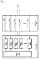
図1を参照すると、コンピューティングシステム100の送信機105及び受信機110の一実施形態を示すブロック図が示されている。送信機105は、チャネル155を介して受信機110に接続されている。チャネル155は、実施形態に応じて、任意の数のデータレーンを含む。また、チャネル155は、レプリカレーン、クロックレーン、及び/又は、1つ以上の他のレーンを含む。コンピューティングシステム100は、クロック145と、クロック150と、図面を不明瞭にするのを避けるために示されていない1つ以上の他のコンポーネントと、を含む。例えば、コンピューティングシステム100は、1つ以上の処理ユニット(例えば、プロセッサ、プロセッサコア、プログラマブルロジックデバイス、特定用途向け集積回路等)、1つ以上のメモリデバイス、及び/又は、他のコンポーネントを含む。1つ以上の処理ユニットは、実施形態に応じて、命令を実行し、及び/又は、1つ以上のタイプの計算(例えば、浮動小数点、整数、メモリ、I/O)を実行するように構成されている。様々な実施形態では、コンピューティングシステム100のコンポーネントは、1つ以上の通信バスによって相互接続されている。一実施形態では、送信機105及び受信機110は、プロセッサのメモリパスに存在する。様々な実施形態において、プロセッサに接続されたメモリは、ダブルデータレート同期ダイナミックランダムアクセスメモリ(DDR SDRAM)である。他の実施形態では、メモリは、他のタイプのメモリデバイスを用いて実装される。
Referring to FIG. 1, a block diagram illustrating one embodiment of a transmitter 105 and a receiver 110 of
送信機105は、チャネル155に接続されたバッファ115を含む。一実施形態では、バッファ115は、トレーニングシーケンスの状態に関して、送信機105が受信機110からのフィードバックを受信するのを待機している場合に、チャネル155の出力を駆動するか、高インピーダンス状態を生成するためのトライステートバッファである。また、送信機105は、トレーニングシーケンスを生成し、チャネル155のレーンの遅延設定を制御し、及び/又は、他の機能を実行する制御ロジック135も含む。さらに、送信機105は、スーパーサイクルをカウントするためのカウンタ125を含む。様々な実施形態では、スーパーサイクルは、長さが「N」クロックサイクルであり、「N」は正の整数である。例えば、一実施形態では、スーパーサイクルは8クロックサイクルの長さであり、他の実施形態では、スーパーサイクルは数クロックサイクルである。一実施形態では、クロック145は、カウンタ125をクロックするためのクロック信号を提供する。
The transmitter 105 includes a
受信機110は、チャネル155に接続するためのバッファ120を含む。一実施形態では、バッファ120は、フィードバック結果をチャネル155に運ぶ、又は、受信機110が送信機105からデータを受信している場合に高インピーダンス状態を生成するためのトライステートバッファである。また、受信機110は、チャネル155上のトレーニングシーケンス指示を検出し、受信したテストパターンを期待値と比較し、チャネル155のレーンの遅延設定を制御し、及び/又は、他の機能を実行する制御ロジック140を含む。さらに、受信機110は、スーパーサイクルをカウントするためのカウンタ130を含む。一実施形態では、クロック150は、カウンタ130をクロックするためのクロック信号を提供する。他の実施形態では、受信機110は、カウンタ130をクロックするためのクロック信号として、チャネル155で受信したクロック信号を使用する。
Receiver 110 includes a
送信機105は、チャネル155のレプリカレーン及び1つ以上のデータレーンを介してテストパターンを送信するように構成されている。テストパターンは、チャネル155のレプリカレーン及びデータレーンの最適なサンプリングポイントを決定するために利用される。レプリカレーン及びデータレーンの遅延は、テストパターンの結果に基づいて調整され、通常のデータオペレーションが開始される。定期的に、送信機105は、データレーンがシステムデータを送る間に、レプリカレーンを介して追加のテストパターンを送信するように構成されている。システム100が、前回のテスト以来レプリカレーンの最適なサンプリングポイントがドリフトしていると判別した場合に、システム100は、レプリカレーンのサンプリングポイントを調整して、最適なサンプリングポイントにアライメントさせる。また、システム100は、データレーンのサンプリングポイントに対して同等の調整を行う。このようにして、温度変動、電源変動、及び/又は、他の要因によるデータレーンのサンプリングポイントのドリフトが、システムデータのフローを中断することなく補正される。
The transmitter 105 is configured to transmit the test pattern via the replica lane of the
受信機110は、レプリカレーン及びデータレーンで送信機105によって送信されたテストパターンをキャプチャするように構成されている。次いで、受信機110は、キャプチャされたテストパターンのエラーに関してチェックする。一実施形態では、送信機105は、トレーニングパターンを送信した後にバッファ115を無効にし、キャプチャされたテストパターンに関するフィードバックを受信機110が送信するのを待機する。受信機110は、バッファ120を有効にし、キャプチャされたテストパターンにおいてエラーが検出されたかどうかを判別した後に、フィードバックを送信機105に送信する。送信機105は、フィードバックをキャプチャし、そのフィードバックを(他の遅延設定を用いた他のテストからのフィードバックと共に)使用して、所定のデータレーンのデータ有効期間(又は、「データアイ」)を決定する。送信機105は、フィードバックをキャプチャした後に、別のテストを実行するかどうか、又は、通常のデータオペレーションに戻るかどうかを決定する。別の実施形態では、受信機110は、キャプチャしたテストパターンにおいて検出されたエラーの数に基づいて、レプリカレーン及びデータレーンの遅延設定を調整する。
The receiver 110 is configured to capture the test pattern transmitted by the transmitter 105 in the replica lane and the data lane. The receiver 110 then checks for errors in the captured test pattern. In one embodiment, the transmitter 105 invalidates the
システム100は、送信機105及び受信機110を含む任意のタイプのコンピューティングシステム又はコンピューティングデバイスを表す。例えば、様々な実施形態では、システム100は、コンピュータ、サーバ、計算ノード、プロセッサ、処理デバイス、プログラマブル論理デバイス、メモリデバイス、プロセッシングインメモリ(PIM)ノード、モバイルデバイス、テレビ、娯楽システム若しくはデバイス、及び/又は、他のタイプのシステム若しくはデバイスを含むことができる。また、システム100は、送信機105及び受信機110に加えて、任意の数の他の送信機及び受信機を含む。
次に、図2を参照すると、レプリカレーンでトレーニングシーケンスを実行する一実施形態のタイミング図200が示されている。トレーニングシーケンスは、複数レーンチャネル(例えば、チャネル155)を介して、送信機(例えば、図1の送信機105)と受信機(例えば、図1の受信機110)との間で実行される。複数レーンチャネルは、レプリカレーンと、システムデータを送るための複数のデータレーンと、を含む。 Referring now to FIG. 2, a timing diagram 200 for one embodiment of performing a training sequence on replica lanes is shown. The training sequence is performed between a transmitter (eg, transmitter 105 of FIG. 1) and a receiver (eg, receiver 110 of FIG. 1) via a multi-lane channel (eg, channel 155). The multi-lane channel includes a replica lane and a plurality of data lanes for transmitting system data.
システムクロック202のサイクルは、タイミング図200の一番上の行に示されている。一実施形態では、タイミング図200のクロック202行に示されるサイクルは、スーパーサイクルを表している。スーパーサイクルは、「N」システムクロックであり、「N」は1より大きい正の整数であり、「N」はプログラマブルレジスタに記憶されている。一実施形態では、送信機及び受信機の両方は、スーパーサイクルをカウントするカウンタを含む。一実施形態では、スーパーサイクルは、長さが8クロックサイクルであり、カウンタは、モジュロ8カウンタである。他の実施形態では、スーパーサイクルは、他の数のクロックサイクルである。レプリカレーン状態204は、タイミング図200に示すクロックサイクル中のチャネルのレプリカレーン状態を示す。レプリカレーン206は、レプリカレーンで送信されるデータを示す。同様に、データレーン状態208は、データレーンの状態を示し、データレーン210は、タイミング図200に示すクロックサイクル中にデータレーンで送信されるデータを示す。
The cycle of the
最初のテストフェーズの間、送信機は、レプリカレーン及びデータレーンでテストパターンを受信機に送信する。これは、レプリカレーン206のテストデータ215及びデータレーン210のテストデータ220として示されている。一実施形態では、テストパターンは、擬似ランダムバイナリシーケンスである。送信機は、レプリカレーン及びデータレーンでテストパターンを送信する前に、テストパターンが送信されることを受信機に知らせるためのトレーニングシーケンス指示を送信する。受信機が所定のレーンでトレーニングシーケンス指示を受信すると、受信機は、所定のレーンでテストパターンを受信する準備が整う。テストデータ215及びテストデータ220は、異なる遅延設定で実行される任意の数のテストに対応する。
During the first test phase, the transmitter sends test patterns in the replica lane and the data lane to the receiver. This is shown as
受信機は、レプリカレーン及びデータレーンでテストパターンを受信し、受信したテストパターンにエラーがあるかどうかをチェックする。一実施形態では、受信機は、受信したテストパターンのエラーの有無に関するフィードバックを送信機に送信する。これは、レプリカレーン及びデータレーンの「待機」状態中に発生する。システムは、テストパターンの結果を使用して、レプリカレーン及びデータレーンの各々のデータアイを識別する。次に、システムは、テストデータの結果に基づいて、レプリカレーン及び各データレーンの位相タイミングを更新する。各レーンは、レーンで受信したテストパターンの結果に基づいて、他のレーンとは独立して更新される。所定のレーンが既に最適なサンプリングポイント用に構成されていることを結果が示している場合、所定のレーンの遅延設定は、位相タイミングの更新期間中に調整されないことに留意されたい。 The receiver receives the test pattern in the replica lane and the data lane, and checks whether the received test pattern has an error. In one embodiment, the receiver sends feedback to the transmitter regarding the presence or absence of errors in the received test pattern. This occurs during the "wait" state of the replica lane and the data lane. The system uses the result of the test pattern to identify the data eye of each of the replica lane and the data lane. Next, the system updates the phase timing of the replica lane and each data lane based on the result of the test data. Each lane is updated independently of the other lanes based on the test pattern results received in the lane. Note that if the results show that a given lane is already configured for the optimal sampling point, then the delay setting for the given lane is not adjusted during the phase timing update period.
レプリカレーン及びデータレーンの位相タイミングへの最初の更新の後、データレーンがシステムデータ230を送る間、レプリカレーンはアイドル状態になる。一定時間が経過すると、システムは、レプリカレーンをテストして、レプリカレーンの位相タイミングがドリフトしているかどうかを確認する。システムがデータレーンでシステムデータ230を送信し続ける一方で、テストデータ225がレプリカレーンで同時に送信される。次に、システムは、テストデータ225が送信された後に、レプリカレーンの位相タイミングを調整するかどうかを決定する。システムは、レプリカレーンで受信したテストパターンの結果に基づいて、以前のテスト以来最適なサンプリングポイントがドリフトした場合に、レプリカレーンの位相タイミングを更新する。この更新は、レプリカレーン状態204の行の更新235として示されている。また、システムは、レプリカレーンでの如何なるドリフトもデータレーンで発生するという仮定に基づいて、データレーンの更新タイミングに対して同様の更新240を実行する。様々な実施形態において、データレーンのタイミングの更新は、データレーンでデータ送信がアクティブである間に(例えば、システムデータ230を送信する間に)実行される。他の実施形態では、データレーンは、更新フェーズ(例えば、240)中にタイミングパラメータが調整される間、データの送信を一時的に中断する。両方のアプローチが考えられる。システムは、レプリカレーン及びデータレーンの位相タイミングの更新235,240の各々の後に、データレーンでのシステムデータの送信に戻る一方で、レプリカレーンはアイドル状態に戻る。次に、レプリカレーンの位相タイミングがドリフトしている場合、システムは、レプリカレーンを定期的にテストして、レプリカレーン及びデータレーンに変更を加えることを継続して行う。
After the first update to the phase timing of the replica lane and the data lane, the replica lane goes idle while the data lane sends
次に、図3を参照すると、送信機305及び通信チャネル320を有する一実施形態のシステム300のブロック図が示されている。通信チャネル320は、送信機305と受信機(図示省略)とを接続する任意のタイプの通信チャネルを表す。通信チャネル320は、実施形態に応じて、レプリカレーン325Aと、任意の数のデータレーン325B〜Nと、を含む。レプリカレーン325Aは、以前のテスト以来最適なサンプリングポイントがドリフトしているかどうかを判別するために、テストデータを送るように構成されている。通常のデータオペレーションでは、レプリカレーン325Aは、システムデータを送るために利用されるのではなく、むしろアイドル状態である。各データレーン325B〜Nは、システムデータのシリアルビットストリームを送るように構成されている。また、通信チャネル320は、クロックレーン(図示省略)及び/又は1つ以上の他のレーンを含む。
Referring now to FIG. 3, a block diagram of an
一実施形態では、送信機305は、制御ロジック310及び遅延素子315A〜Nを含む。遅延素子315A〜Nの個々のセットは、レーン325A〜Nのうち対応するレーンの遅延設定を選択するための1つ以上の遅延素子を含む。一実施形態では、1つ以上の遅延素子は、レーン325A〜Nのうち単一のレーンに適用される粗い遅延調整及び細かい遅延調整を含む。
In one embodiment, transmitter 305 includes
送信機305は、最初のテスト期間中にレーン325A〜Nの遅延設定をテストするために、レーン325A〜Nの全てでテストパターンを送信するように構成されている。例えば、この最初のテスト期間は、起動時又はリセット後に発生する。送信機は、テストパターンを送信した後に、出力バッファ(例えば、図1のバッファ115)を無効にする。出力バッファは、送信機305がテストパターンを受信機に送信した後に、送信機305によって高インピーダンス状態に切り替えられるトライステートバッファである。受信機は、フィードバックを準備する期間の後に、出力バッファを起動して、フィードバックを送信機に送る。一実施形態では、フィードバックは、受信したテストパターンにエラーがあったかどうかを示す。一実施形態では、フィードバックは、単一のビットである。他の実施形態では、フィードバックは、エラーの数を示すために複数のビットを利用する。送信機は、フィードバックを受信し、フィードバックを利用して、現在の遅延設定がデータアイ内側か外側かを判別する。送信機がフィードバックを受信した後に、別のテストが実行されてもよいし、送信機が通常のデータオペレーションを行ってもよい。 The transmitter 305 is configured to transmit a test pattern on all lanes 325A-N to test the delay settings of lanes 325A-N during the first test period. For example, this first test period occurs at start-up or after reset. The transmitter invalidates the output buffer (eg, buffer 115 of FIG. 1) after transmitting the test pattern. The output buffer is a tri-state buffer that the transmitter 305 switches to a high impedance state after the transmitter 305 sends the test pattern to the receiver. The receiver activates the output buffer to send the feedback to the transmitter after the period for preparing the feedback. In one embodiment, the feedback indicates whether the received test pattern was in error. In one embodiment, the feedback is a single bit. In other embodiments, the feedback utilizes multiple bits to indicate the number of errors. The transmitter receives the feedback and uses the feedback to determine whether the current delay setting is inside or outside the data eye. Another test may be performed after the transmitter receives the feedback, or the transmitter may perform normal data operation.
一実施形態では、送信機305は、各レーンでテストパターンを送信し、受信機(図示省略)は、各テストパターンにおいて検出されたエラーの数と共にフィードバックを送信機305に送る。次に、送信機305の制御ロジック310は、このフィードバックを利用して、各レーン325A〜Nのデータアイを決定する。例えば、送信機は、チャネル320のレーン325A〜N毎に、異なる遅延設定を有する複数のテストパターンを送信する。これらのテストパターンに対する受信機からのフィードバックは、制御ロジック310によって、各レーンのデータアイの位置を決定するために使用される。制御ロジック310は、遅延素子315A〜Nの各々を調整して、対応するレーンの受信機のサンプリングポイントを、データアイの位置に基づく最適なサンプリングポイントに対応させる。遅延素子315A〜Nの各々に対する調整は、他の遅延素子315A〜Nに対する調整とは独立して行われる。
In one embodiment, the transmitter 305 sends a test pattern in each lane and a receiver (not shown) sends feedback to the transmitter 305 along with the number of errors detected in each test pattern. The
次に、システム300は、全てのレーン325A〜Nについて位相テストシーケンスを実行した後に、通常のデータオペレーションを開始する。データレーン325B〜Nは、通常のデータオペレーションの間、システムデータを送るために利用される一方で、レプリカレーン325Aは、アイドル状態である。換言すれば、レプリカレーン325Aは、システムデータを送るために使用されない。次に、システム300は、通常のデータオペレーションの間、レプリカレーン325Aを周期的に利用して、以前のテストからフェーズタイミングがドリフトしているかどうかを確認するために、位相テストを行う。実施形態に応じて、レプリカレーン325Aの位相タイミングは、温度変動、電源変動、及び/又は、要因に基づいてドリフトする。システム300は、データレーン325B〜Nがシステムデータを送っている間に、レプリカレーン325Aにおける位相テストを実行する。このように、システム300は、データレーン325B〜Nのシステムデータのフローを中断することなく、レプリカレーン325Aの位相タイミングをテストすることができる。
The
システム300がレプリカレーン325Aの位相タイミングのドリフトを検出すると、システム300は、遅延素子315Aを調整することによって、レプリカレーン325Aのタイミングを補正する。また、システム300は、データレーン325B〜Nに影響を与える他の遅延素子315B〜Nにも同じ調整を行う。多くの場合、レプリカレーン325Aの位相タイミングで発生したドリフトは、データレーン325B〜Nにおいても発生している。したがって、システム300は、全てのレーン325A〜Nの位相タイミングのドリフトを、単一のレプリカレーン325Aのテストを実行するだけで補正することができる。一実施形態では、システム300は、規則的な間隔で、単一のレプリカレーン325Aでこれらのテストを実行するように構成されている。別の実施形態では、システム300は、1つ以上の条件(例えば、エラー率の増加、温度変動、電源変動等)の検出に応じて、レプリカレーン325Aに対するテストを実行するように構成されている。
When
次に、図4を参照すると、通信チャネル405及び受信機415を備える一実施形態のシステム400のブロック図が示されている。図3のシステム300と同様に、システム400は、レプリカレーン410Aの位相タイミングのドリフトの検出に基づいて、データレーン410B〜Nの位相タイミングを補正するように構成されている。しかし、システム300とは対照的に、システム400は、遅延素子420A〜Nを用いて、受信機415における位相タイミングの補正を行う。本実施形態では、受信機415の制御ロジック425は、フィードバックを送信機(図示省略)に送信するのではなく、受信したテストパターンに対するフィードバックを利用して、遅延素子420A〜Nを調整する。
Referring now to FIG. 4, a block diagram of an
次に、図5を参照すると、データアイ500の一実施形態の図が示されている。データアイ500は、チャネル(例えば、図3の通信チャネル320)のレーンでのビット遷移をキャプチャすることによってモニタリングされるデータ有効期間の一例である。一実施形態では、システム(例えば、システム300)は、データアイ500の境界を検出するために、異なる遅延設定で複数のトレーニングシーケンスを実行するように構成されている。システムは、各テスト結果について受信機(例えば、図1の受信機110)が生成したフィードバックを利用するよう構成されている。
Referring now to FIG. 5, a diagram of one embodiment of
システムは、複数の遅延設定で複数のテストを実行し、フィードバックが不良(すなわち、1つ以上のエラーがある)から良好(すなわち、エラーがない)になると、その特定の遅延設定がデータアイ500の開始510と一致すると認識する。システムは、僅かな増分で遅延を追加し、追加のテストを実行し、フィードバックが良好から不良になると、これをデータアイ500の終了520と識別する。次に、システムは、データアイ500の中央530を算出するために、開始510及び終了520の平均をもとめる。データアイ500の中央530に対応する遅延設定は、チャネルの所定のレーンに対する最適な遅延設定とみなされる。一実施形態では、システムは、チャネルのレプリカレーンでこれらのテストを実行し、次いで、これらのテストの結果を利用して、チャネルのデータレーンの遅延設定を更新する。
The system performs multiple tests with multiple delay settings, and when the feedback goes from bad (ie, there is one or more errors) to good (ie, no errors), that particular delay setting is set to the
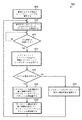
次に、図6を参照すると、マルチレーンチャネルの位相タイミングを調整する方法600の一実施形態が示されている。説明目的のために、本実施形態におけるステップは、順番に示されている。後述する方法の様々な実施形態において、説明する要素のうち1つ以上が同時に実行されてもよいし、図示した順序とは異なる順序で実行されてもよいし、完全に省略されてもよいことに留意されたい。必要に応じて、他の追加の要素を実行してもよい。本明細書において説明する様々なシステム又は装置の何れかは、方法600を実行するように構成されている。
Referring now to FIG. 6, illustrated is an embodiment of a
複数レーン通信チャネルを介して受信機に接続された送信機を有するシステムは、チャネルの複数のレーンでトレーニングシーケンスを同時に実行する(ブロック605)。一実施形態では、通信チャネルは、レプリカレーン及び1つ以上のデータレーンを含む。チャネルの複数のレーンでトレーニングシーケンスを実行する一環として、システムは、レーンの遅延設定を更新して、各レーンが着信データを最適なサンプリングポイントでサンプリングするようにする。 A system having a transmitter connected to a receiver via a multi-lane communication channel simultaneously executes a training sequence on multiple lanes of the channel (block 605). In one embodiment, the communication channel includes a replica lane and one or more data lanes. As part of performing the training sequence on multiple lanes of a channel, the system updates the lane delay settings so that each lane samples incoming data at the optimal sampling point.
次に、システムは、通常のデータオペレーションのためにデータレーンを利用することができる(ブロック610)。通常のデータオペレーションの間、チャネルのレプリカレーンはアイドル状態である。次に、システムは、最後のトレーニングシーケンスが実行されてから所定時間が経過したかどうかを判別する(条件ブロック615)。例えば、システムは、所定時間を追跡するタイマを有し、所定時間は、プログラム可能であって、実施形態毎に異なる。 The system may then utilize the data lane for normal data operation (block 610). During normal data operation, the replica lane of the channel is idle. The system then determines if a predetermined amount of time has elapsed since the last training sequence was performed (condition block 615). For example, the system has a timer that tracks a predetermined time, which is programmable and varies from embodiment to embodiment.
システムは、所定時間が経過した場合(条件ブロック615:「Yes」)、レプリカレーンで1つ以上のトレーニングシーケンスを実行し、同時にデータレーンでシステムデータを送信する(ブロック620)。所定時間が経過していない場合(条件ブロック615:「No」)、方法600は、条件ブロック615に留まる。システムは、ブロック620の後に、レプリカレーンで実行されたトレーニングシーケンスが、レプリカレーンの最適なサンプリングポイントが以前のテストからドリフトしたことを表しているかどうかを判別する(条件ブロック625)。
The system performs one or more training sequences in the replica lane and transmits system data in the data lane at the same time (block 620) if the predetermined amount of time has elapsed (condition block 615: “Yes”). If the predetermined time has not elapsed (condition block 615: “No”),
レプリカレーンの最適なサンプリングポイントが以前のテストからドリフトしている場合(条件ブロック625:「Yes」)、システムは、レプリカレーンの遅延設定に第1調整を適用して、レプリカレーンのサンプリングポイントを再調整する(ブロック630)。また、システムは、チャネルのデータレーンの遅延設定に第1調整を適用して、データレーンのサンプリングポイントを再調整する(ブロック635)。このシステムは、レプリカレーンの最適なサンプリングポイントのドリフトがデータレーンで発生することを前提として動作する。したがって、システムは、レプリカレーンの遅延設定に適用されるのと同じ調整を、データレーンの遅延設定に適用する。例えば、第1の量の遅延がレプリカレーンの遅延設定に加えられた場合、第1の量の遅延がデータレーンの遅延設定に加えられる。レプリカレーンの最適なサンプリングポイントが以前のテストからドリフトしていない場合(条件ブロック625:「No」)、システムは、レプリカレーン及びデータレーンの現在の遅延設定を維持する(ブロック640)。ブロック635,640の後に、方法600はブロック610に戻り、システムは、通常のデータオペレーションのためにデータレーンを利用し続ける。
If the replica lane's optimal sampling point is drifting from the previous test (condition block 625: “Yes”), the system applies a first adjustment to the replica lane's delay setting to determine the replica lane's sampling point. Readjust (block 630). The system also applies a first adjustment to the delay settings of the data lanes of the channel to readjust the sampling points of the data lanes (block 635). This system operates on the assumption that the optimum sampling point drift of the replica lane occurs in the data lane. Therefore, the system applies the same adjustments to the delay settings for the data lanes as it applies to the delay settings for the replica lanes. For example, if a first amount of delay is added to the replica lane's delay setting, then a first amount of delay is added to the data lane's delay setting. If the optimal sampling point for the replica lane has not drifted from the previous test (condition block 625: “No”), the system maintains the current delay settings for the replica lane and the data lane (block 640). After
次に、図7を参照すると、チャネルの他のレーンのサンプリングポイントを調整するためにレプリカレーンを利用する方法700の一実施形態が示されている。説明目的のために、本実施形態におけるステップは、順番に示されている。後述する方法の様々な実施形態において、説明する要素のうち1つ以上が同時に実行されてもよいし、図示した順序とは異なる順序で実行されてもよいし、完全に省略されてもよいことに留意されたい。必要に応じて、他の追加の要素を実行してもよい。本明細書において説明する様々なシステム又は装置の何れかは、方法700を実行するように構成されている。
Referring now to FIG. 7, one embodiment of a
送信機は、複数レーンチャネルの第1レーンで、1つ以上のテストパターンを受信機に送信すると同時に、チャネルの第2レーンで第1データを送信する(ブロック705)。送信機及び受信機は、ホストシステム内のコンポーネントである。第1レーンは、「レプリカレーン」と呼ぶこともある。1つ以上のテストパターンは、トレーニングシーケンスの一部として第1レーンで受信機に送信され、送信機及び受信機間の第1レーンの遅延設定をテストする。これらのトレーニングシーケンスを使用して、第1レーンのデータアイの位置を決定し、データアイ(及び、対応する最適なサンプリングポイント)が以前のテストからシフトしたかどうかを判別する。 The transmitter transmits one or more test patterns to the receiver on the first lane of the multi-lane channel while transmitting first data on the second lane of the channel (block 705). The transmitter and receiver are components within the host system. The first lane may be referred to as a “replica lane”. One or more test patterns are sent to the receiver on the first lane as part of the training sequence to test the delay setting on the first lane between the transmitter and the receiver. These training sequences are used to determine the position of the data eye in the first lane and determine if the data eye (and the corresponding optimal sampling point) has shifted from the previous test.
次に、システムは、受信機によって受信されたテストパターンの結果に基づいて、第1レーンの現在のサンプリングポイントがミスアライメントされているかどうかを判別する(条件ブロック710)。例えば、システムは、複数の遅延設定で第1レーンの複数のテストを実行し、受信したテストパターンが1つ以上のエラーを有する状態からエラーのない状態になると、その特定の遅延設定がデータアイの開始と一致すると認識する。システムは、僅かな増分で遅延を追加し、追加のテストを実行し、受信したテストパターンがエラーのない状態から1つ以上のエラーを有する状態になると、データアイの終了であると認識する。システムは、データアイの開始及び終了の平均をもとめて、データアイの中央(又は、最適なサンプリングポイント)を計算する。次に、システムは、この新たな最適なサンプリングポイントが第1レーンの実際のサンプリングポイントと一致するかどうかを判別する。他の実施形態では、システムは、最適なサンプリングポイントが第1レーンに対してドリフトしたかどうかを判別するための他の適切な技術を利用する。 Next, the system determines whether the current sampling point of the first lane is misaligned based on the result of the test pattern received by the receiver (condition block 710). For example, the system may perform multiple tests in the first lane with multiple delay settings, and when the received test pattern goes from having one or more errors to being error free, that particular delay setting may cause the data eye Recognize that it matches the start of. The system adds a delay in small increments, performs additional tests, and recognizes the end of the data eye when the received test pattern goes from error-free to one or more errors. The system calculates the center (or optimal sampling point) of the data eye by averaging the start and end of the data eye. The system then determines if this new optimal sampling point matches the actual sampling point in the first lane. In other embodiments, the system utilizes other suitable techniques for determining if the optimal sampling point has drifted relative to the first lane.
システムは、受信機によって受信されたテストパターンの結果に基づいて、第1レーンの現在のサンプリングポイントがミスアライメントしていると判別した場合(条件ブロック710:「Yes」)、第1レーンのサンプリングポイントに対して第1調整を行って、サンプリングポイントを最適なサンプリングポイントにアライメントし直す(ブロック715)。また、システムは、チャネルの第2レーンのサンプリングポイントに対して第1調整を行う(ブロック720)。さらに、システムは、チャネルの1つ以上の他のレーンのサンプリングポイントに対して第1調整を行う。例えば、一実施形態では、システムは、チャネルの全てのデータレーンのサンプリングポイントに対して第1調整を行う。システムが、受信機によって受信されたテストパターンの結果に基づいて、第1レーンのサンプリングポイントが適切にアライメントされていると判別した場合(条件ブロック710:「No」の分岐)、送信機は、第2レーンで第2データを送信する(ブロック725)。 If the system determines that the current sampling point of the first lane is misaligned based on the result of the test pattern received by the receiver (condition block 710: “Yes”), the sampling of the first lane is performed. A first adjustment is made to the points to realign the sampling points with the optimal sampling points (block 715). The system also makes a first adjustment to the sampling points of the second lane of the channel (block 720). In addition, the system makes a first adjustment to sampling points in one or more other lanes of the channel. For example, in one embodiment, the system makes a first adjustment to the sampling points of all data lanes of the channel. If the system determines that the sampling points in the first lane are properly aligned based on the results of the test pattern received by the receiver (condition block 710: “No” branch), the transmitter The second data is transmitted on the second lane (block 725).
温度変動、電源変動、及び/又は、他の要因によって、同様の方法で第1レーン及び他のレーンについて信号遅延の変動が生じる。したがって、第1レーンの最適なサンプリングポイントの変化を検出することは、典型的に、他のレーンがデータアイにおいて同様のドリフトを経験したことと、第1レーンを補正するための変更が、チャネルの他のレーンを補正するのに必要とされる同じ変更であることと、を表す。したがって、チャネルの第2レーン(及び、他のレーン)に対して行われる第1調整は、第1レーンに対して行われる第1調整と同じである。例えば、第1調整が、第1レーンに加える遅延をクロックサイクルの1/4だけ増加させる場合、他のレーンに加わる遅延は、クロックサイクルの1/4だけ増加する。或いは、第1調整が、第1レーンに加える遅延をクロックサイクルの1/8だけ減少させる場合、他のレーンに加わる遅延は、クロックサイクルの1/8だけ減少する。他の実施形態では、他の遅延増分が、第1レーンに対して行われた調整と同等の方法で、レーンに追加又はレーンから削除される。一実施形態では、サンプリングポイントに対する調整は、送信機によって行われる。別の実施形態では、サンプリングポイントに対する調整は、受信機によって行われる。 Variations in temperature, power variations, and/or other factors cause variations in signal delay for the first lane and other lanes in a similar manner. Therefore, detecting changes in the optimal sampling point of the first lane typically means that other lanes have experienced similar drift in the data eye and that changes to correct the first lane are , The same changes needed to correct the other lanes of. Therefore, the first adjustment made to the second lane (and other lanes) of the channel is the same as the first adjustment made to the first lane. For example, if the first adjustment increases the delay on the first lane by 1/4 of a clock cycle, the delay on the other lanes is increased by 1/4 of a clock cycle. Alternatively, if the first adjustment reduces the delay applied to the first lane by 1/8 of a clock cycle, the delay applied to the other lanes is decreased by 1/8 of a clock cycle. In other embodiments, other delay increments are added to or removed from the lane in a manner similar to the adjustments made to the first lane. In one embodiment, the adjustments to the sampling points are made by the transmitter. In another embodiment, the adjustments to the sampling points are made by the receiver.
ブロック720の後、送信機は、第2レーンで第2データを送信する(ブロック725)。また、送信機は、他のレーンに使用されるサンプリングポイントの調整を行った後に、チャネルの1つ以上の他のレーンで追加のデータを送信する。ブロック725の後に、方法700は終了する。
After
様々な実施形態では、ソフトウェアアプリケーションのプログラム命令は、上述した方法及び/又はメカニズムを実施するために使用される。プログラム命令には、C等の高水準プログラミング言語でハードウェアの動作が記述されている。或いは、Verilog等のハードウェア設計言語(HDL)が使用される。プログラム命令は、非一時的なコンピュータ可読記憶媒体に記憶される。多数のタイプの記憶媒体が利用可能である。記憶媒体は、プログラム実行のためにプログラム命令及び付随データをコンピューティングシステムに提供するために、使用中にコンピューティングシステムによってアクセス可能である。コンピューティングシステムは、少なくとも1つ以上のメモリと、プログラム命令を実行するように構成された1つ以上のプロセッサと、を含む。 In various embodiments, software application program instructions are used to implement the methods and/or mechanisms described above. The operation of the hardware is described in the program instruction in a high level programming language such as C. Alternatively, a hardware design language (HDL) such as Verilog is used. The program instructions are stored on a non-transitory computer readable storage medium. Many types of storage media are available. A storage medium is accessible by a computing system during use to provide the program instructions and associated data to the computing system for program execution. The computing system includes at least one or more memories and one or more processors configured to execute program instructions.
上述した実施形態は、実装の非限定的な例に過ぎないことが強調されるべきである。上記の開示を十分に理解することで、多数の変形及び修正が当業者に明らかになるであろう。以下の特許請求の範囲は、このような変形及び修正の全てを包含すると解釈されることが意図される。 It should be emphasized that the embodiments described above are merely non-limiting examples of implementations. Many variations and modifications will be apparent to those of ordinary skill in the art upon a thorough understanding of the above disclosure. The following claims are intended to be construed to cover all such variations and modifications.
Claims (8)
第1レーンと第2レーンとを少なくとも含む複数のレーンを有する通信チャネルを介して前記受信機に接続された送信機であって、前記第1レーンは、システムデータを伝送するために利用されない、送信機と、
を備えるシステムであって、
前記送信機は、
前記通信チャネルの前記第1レーンでテストパターンを送信し、
前記通信チャネルの第2レーンでシステムデータを送信するのと同時に、前記第1レーンで前記テストパターンを送信する、
ように構成されており、
前記受信機は、
前記第2レーンで前記システムデータを受信するのと同時に、前記通信チャネルの前記第1レーンを介してテストパターンを受信し、
受信したテストパターンにおいて検出されたエラーに基づいて、前記第1レーンのサンプリングポイントがミスアライメントであると判別し、
前記テストパターンにおいて前記エラーが検出されたことを示すエラー表示を、前記第1レーンを介して前記送信機に伝える、
ように構成されており、
前記システムは、前記検出されたエラーに応じて、
前記第1レーンのサンプリングポイントに対して第1調整を実行し、
前記通信チャネルの前記第2レーンのサンプリングポイントに対して、前記第1調整と同じ調整である第2調整を実行する、
ように構成されている、
システム。 A receiver,
A transmitter connected to the receiver via a communication channel having a plurality of lanes including at least a first lane and a second lane, wherein the first lane is not used to transmit system data, A transmitter,
A system comprising
The transmitter is
Transmitting a test pattern on the first lane of the communication channel,
At the same time as transmitting system data on the second lane of the communication channel, transmitting the test pattern on the first lane,
Is configured as
The receiver is
At the same time as receiving the system data in the second lane, receiving a test pattern through the first lane of the communication channel,
It is determined that the sampling point of the first lane is misaligned based on the error detected in the received test pattern,
An error indication indicating that the error has been detected in the test pattern is transmitted to the transmitter via the first lane,
Is configured as
The system is responsive to the detected error to
Performing a first adjustment on the sampling points of the first lane,
Performing a second adjustment, which is the same adjustment as the first adjustment, on the sampling points of the second lane of the communication channel,
Is configured as
system.
前記トレーニングは、テストパターンデータを前記第1レーン及び前記第2レーンで伝えることと、前記第1レーン及び前記第2レーンの遅延設定を更新して前記第1レーンのサンプリングポイントと前記第2レーンのサンプリングポイントとを調整することと、を含む、
請求項1のシステム。 The system is configured to perform an initial phase before performing the first adjustment and the second adjustment, and the system is configured to perform the first lane and the second lane during the initial phase. It is configured to set a sampling point of the first lane and a sampling point of the second lane in response to training both at the same time,
In the training, the test pattern data is transmitted in the first lane and the second lane, and the delay settings of the first lane and the second lane are updated to update the sampling points of the first lane and the second lane. And adjusting the sampling points of
The system of claim 1.
請求項1のシステム。 The transmitter changes a delay setting of the first lane to perform the first adjustment with respect to a sampling point of the first lane in response to receiving the error indication in the first lane. Is configured as
The system of claim 1 .
請求項1のシステム。 The transmitter changes the delay setting of the second lane to perform the second adjustment with respect to the sampling point of the second lane in response to receiving the error indication in the first lane. Is configured as
The system of claim 1 .
請求項4のシステム。 The second adjustment for the sampling points of the second lane is performed without transmitting a test pattern in the second lane.
The system of claim 4 .
前記送信機が、前記通信チャネルの第2レーンでシステムデータを送信するのと同時に、前記第1レーンで前記テストパターンを送信することと、
前記テストパターンにおいて前記エラーが検出されたことを示すエラー表示を、前記第1レーンを介して受信することと、
受信機によって受信された前記テストパターンにおいて検出されたエラーの数に基づいて、前記第1レーンのサンプリングポイントがミスアライメントであると判別したことに応じて、前記第1レーンのサンプリングポイントに対して第1調整を実行し、前記通信チャネルの第2レーンによって利用されるサンプリングポイントに対して、前記第1調整と同じ調整である第2調整を実行することと、を含む、
方法。 A transmitter transmitting a test pattern on a first lane of a communication channel, said first lane not being used to transmit system data;
The transmitter transmits system data on a second lane of the communication channel and at the same time transmits the test pattern on the first lane;
Receiving an error indication indicating that the error has been detected in the test pattern via the first lane;
In response to determining that the sampling point of the first lane is misaligned based on the number of errors detected in the test pattern received by the receiver, the sampling point of the first lane is Performing a first adjustment and performing a second adjustment that is the same adjustment as the first adjustment on a sampling point utilized by a second lane of the communication channel.
Method.
前記方法は、前記初期フェーズ中に、前記第1レーン及び前記第2レーンの両方を同時にトレーニングすることに応じて、前記第1レーンのサンプリングポイントと、前記第2レーンのサンプリングポイントと、を設定することを含み、
前記トレーニングは、テストパターンデータを前記第1レーン及び前記第2レーンで伝えることと、前記第1レーン及び前記第2レーンの遅延設定を更新して前記第1レーンのサンプリングポイントと前記第2レーンのサンプリングポイントとを調整することと、を含む、
請求項6の方法。 Performing an initial phase before performing the first adjustment and the second adjustment,
The method sets a sampling point of the first lane and a sampling point of the second lane in response to simultaneously training both the first lane and the second lane during the initial phase. Including doing
In the training, the test pattern data is transmitted in the first lane and the second lane, and the delay settings of the first lane and the second lane are updated to update the sampling points of the first lane and the second lane. And adjusting the sampling points of
The method of claim 6 .
請求項6の方法。 The transmitter changes a delay setting of the first lane to perform the first adjustment for a sampling point of the first lane in response to receiving the error indication in the first lane. And/or changing a delay setting of the second lane to perform the second adjustment with respect to a sampling point of the second lane,
The method of claim 6 .
Applications Claiming Priority (3)
| Application Number | Priority Date | Filing Date | Title |
|---|---|---|---|
| US15/192,287 US10749756B2 (en) | 2016-06-24 | 2016-06-24 | Channel training using a replica lane |
| US15/192,287 | 2016-06-24 | ||
| PCT/US2016/052725 WO2017222578A1 (en) | 2016-06-24 | 2016-09-21 | Channel training using a replica lane |
Publications (3)
| Publication Number | Publication Date |
|---|---|
| JP2019525507A JP2019525507A (en) | 2019-09-05 |
| JP2019525507A5 JP2019525507A5 (en) | 2019-10-31 |
| JP6703134B2 true JP6703134B2 (en) | 2020-06-03 |
Family
ID=60675203
Family Applications (1)
| Application Number | Title | Priority Date | Filing Date |
|---|---|---|---|
| JP2018556345A Active JP6703134B2 (en) | 2016-06-24 | 2016-09-21 | Channel training with replica lanes |
Country Status (5)
| Country | Link |
|---|---|
| US (2) | US10749756B2 (en) |
| JP (1) | JP6703134B2 (en) |
| KR (1) | KR102572281B1 (en) |
| CN (1) | CN109076036B (en) |
| WO (1) | WO2017222578A1 (en) |
Families Citing this family (3)
| Publication number | Priority date | Publication date | Assignee | Title |
|---|---|---|---|---|
| US10749756B2 (en) | 2016-06-24 | 2020-08-18 | Advanced Micro Devices, Inc. | Channel training using a replica lane |
| US11558120B1 (en) * | 2021-09-30 | 2023-01-17 | United States Of America As Represented By The Administrator Of Nasa | Method for deskewing FPGA transmitter channels directly driving an optical QPSK modulator |
| US11906585B2 (en) * | 2021-12-16 | 2024-02-20 | Samsung Electronics Co., Ltd. | Methods and systems for performing built-in-self-test operations without a dedicated clock source |
Family Cites Families (29)
| Publication number | Priority date | Publication date | Assignee | Title |
|---|---|---|---|---|
| US5469748A (en) * | 1994-07-20 | 1995-11-28 | Micro Motion, Inc. | Noise reduction filter system for a coriolis flowmeter |
| US6178213B1 (en) * | 1998-08-25 | 2001-01-23 | Vitesse Semiconductor Corporation | Adaptive data recovery system and methods |
| US20020093986A1 (en) * | 2000-12-30 | 2002-07-18 | Norm Hendrickson | Forward data de-skew method and system |
| US6907552B2 (en) * | 2001-08-29 | 2005-06-14 | Tricn Inc. | Relative dynamic skew compensation of parallel data lines |
| US7072355B2 (en) | 2003-08-21 | 2006-07-04 | Rambus, Inc. | Periodic interface calibration for high speed communication |
| US7095789B2 (en) | 2004-01-28 | 2006-08-22 | Rambus, Inc. | Communication channel calibration for drift conditions |
| US7400670B2 (en) * | 2004-01-28 | 2008-07-15 | Rambus, Inc. | Periodic calibration for communication channels by drift tracking |
| US7516029B2 (en) * | 2004-06-09 | 2009-04-07 | Rambus, Inc. | Communication channel calibration using feedback |
| US7500131B2 (en) | 2004-09-07 | 2009-03-03 | Intel Corporation | Training pattern based de-skew mechanism and frame alignment |
| US20080130815A1 (en) * | 2006-12-05 | 2008-06-05 | Kumar S Reji | Selective tracking of serial communication link data |
| US7467056B2 (en) * | 2007-03-09 | 2008-12-16 | Nortel Networks Limited | Method and apparatus for aligning multiple outputs of an FPGA |
| US7590789B2 (en) * | 2007-12-07 | 2009-09-15 | Intel Corporation | Optimizing clock crossing and data path latency |
| US8307265B2 (en) | 2009-03-09 | 2012-11-06 | Intel Corporation | Interconnection techniques |
| US20110040902A1 (en) | 2009-08-13 | 2011-02-17 | Housty Oswin E | Compensation engine for training double data rate delays |
| US8582706B2 (en) * | 2009-10-29 | 2013-11-12 | National Instruments Corporation | Training a data path for parallel data transfer |
| KR101110820B1 (en) * | 2010-05-28 | 2012-02-27 | 주식회사 하이닉스반도체 | Slave device, system including master device and slave device and operation method of the system, chip package |
| US8681839B2 (en) | 2010-10-27 | 2014-03-25 | International Business Machines Corporation | Calibration of multiple parallel data communications lines for high skew conditions |
| US8767531B2 (en) * | 2010-10-27 | 2014-07-01 | International Business Machines Corporation | Dynamic fault detection and repair in a data communications mechanism |
| US8774228B2 (en) * | 2011-06-10 | 2014-07-08 | International Business Machines Corporation | Timing recovery method and apparatus for an input/output bus with link redundancy |
| US8826092B2 (en) * | 2011-10-25 | 2014-09-02 | International Business Machines Corporation | Characterization and validation of processor links |
| WO2013137863A1 (en) * | 2012-03-13 | 2013-09-19 | Rambus Inc. | Clock and data recovery having shared clock generator |
| US9071407B2 (en) * | 2012-05-02 | 2015-06-30 | Ramnus Inc. | Receiver clock test circuitry and related methods and apparatuses |
| US8760946B2 (en) * | 2012-05-22 | 2014-06-24 | Advanced Micro Devices | Method and apparatus for memory access delay training |
| US9030341B2 (en) | 2012-06-27 | 2015-05-12 | Broadcom Corporation | Compensation for lane imbalance in a multi-lane analog-to-digital converter (ADC) |
| US20140281085A1 (en) | 2013-03-15 | 2014-09-18 | Gregory L. Ebert | Method, apparatus, system for hybrid lane stalling or no-lock bus architectures |
| CN103560785B (en) * | 2013-10-28 | 2017-05-10 | 中国电子科技集团公司第四十一研究所 | Method and device for generating phase-coherent signals |
| US9036757B1 (en) | 2014-09-23 | 2015-05-19 | Oracle International Corporation | Post-cursor locking point adjustment for clock data recovery |
| WO2017052663A1 (en) * | 2015-09-26 | 2017-03-30 | Intel Corporation | Valid lane training |
| US10749756B2 (en) | 2016-06-24 | 2020-08-18 | Advanced Micro Devices, Inc. | Channel training using a replica lane |
-
2016
- 2016-06-24 US US15/192,287 patent/US10749756B2/en active Active
- 2016-09-21 CN CN201680085663.5A patent/CN109076036B/en active Active
- 2016-09-21 KR KR1020187033047A patent/KR102572281B1/en active IP Right Grant
- 2016-09-21 JP JP2018556345A patent/JP6703134B2/en active Active
- 2016-09-21 WO PCT/US2016/052725 patent/WO2017222578A1/en active Application Filing
-
2020
- 2020-08-14 US US16/993,678 patent/US11805026B2/en active Active
Also Published As
| Publication number | Publication date |
|---|---|
| CN109076036B (en) | 2022-01-28 |
| CN109076036A (en) | 2018-12-21 |
| KR102572281B1 (en) | 2023-08-29 |
| US20170373944A1 (en) | 2017-12-28 |
| WO2017222578A1 (en) | 2017-12-28 |
| KR20190011727A (en) | 2019-02-07 |
| JP2019525507A (en) | 2019-09-05 |
| US11805026B2 (en) | 2023-10-31 |
| US20210028995A1 (en) | 2021-01-28 |
| US10749756B2 (en) | 2020-08-18 |
Similar Documents
| Publication | Publication Date | Title |
|---|---|---|
| US11805026B2 (en) | Channel training using a replica lane | |
| US8644085B2 (en) | Duty cycle distortion correction | |
| US9832006B1 (en) | Method, apparatus and system for deskewing parallel interface links | |
| US8286024B2 (en) | Memory device, host device, and sampling clock adjusting method | |
| US6978403B2 (en) | Deskew circuit and disk array control device using the deskew circuit, and deskew method | |
| US20140351359A1 (en) | Data processing apparatus and method for communicating between a master device and an asychronous slave device via an interface | |
| US9715270B2 (en) | Power reduction in a parallel data communications interface using clock resynchronization | |
| JP5835464B2 (en) | Information processing apparatus and information processing apparatus control method | |
| CN115116489A (en) | Training method and related device for DERR pin of high-bandwidth memory | |
| CN102668378B (en) | Information processing apparatus or information processing method | |
| EP3260983B1 (en) | Channel training using a replica lane | |
| US6519664B1 (en) | Parallel terminated bus system | |
| US10103837B2 (en) | Asynchronous feedback training | |
| JP2012119782A (en) | Node system and monitoring node | |
| JP3671782B2 (en) | Signal phase adjustment circuit | |
| US9746876B2 (en) | Drift compensation for a real time clock circuit | |
| US10951198B1 (en) | Semiconductor integrated circuit, transmission device, and memory device | |
| EP3260984B1 (en) | Asynchronous feedback training | |
| US7017086B2 (en) | Round-robin updating for high speed I/O parallel interfaces | |
| US10467171B2 (en) | Detecting the drift of the data valid window in a transaction |
Legal Events
| Date | Code | Title | Description |
|---|---|---|---|
| A521 | Request for written amendment filed |
Free format text: JAPANESE INTERMEDIATE CODE: A523 Effective date: 20190918 |
|
| A621 | Written request for application examination |
Free format text: JAPANESE INTERMEDIATE CODE: A621 Effective date: 20190918 |
|
| A871 | Explanation of circumstances concerning accelerated examination |
Free format text: JAPANESE INTERMEDIATE CODE: A871 Effective date: 20190918 |
|
| A975 | Report on accelerated examination |
Free format text: JAPANESE INTERMEDIATE CODE: A971005 Effective date: 20190926 |
|
| A131 | Notification of reasons for refusal |
Free format text: JAPANESE INTERMEDIATE CODE: A131 Effective date: 20191001 |
|
| A601 | Written request for extension of time |
Free format text: JAPANESE INTERMEDIATE CODE: A601 Effective date: 20191220 |
|
| A601 | Written request for extension of time |
Free format text: JAPANESE INTERMEDIATE CODE: A601 Effective date: 20200302 |
|
| A521 | Request for written amendment filed |
Free format text: JAPANESE INTERMEDIATE CODE: A523 Effective date: 20200331 |
|
| TRDD | Decision of grant or rejection written | ||
| A01 | Written decision to grant a patent or to grant a registration (utility model) |
Free format text: JAPANESE INTERMEDIATE CODE: A01 Effective date: 20200407 |
|
| A61 | First payment of annual fees (during grant procedure) |
Free format text: JAPANESE INTERMEDIATE CODE: A61 Effective date: 20200507 |
|
| R150 | Certificate of patent or registration of utility model |
Ref document number: 6703134 Country of ref document: JP Free format text: JAPANESE INTERMEDIATE CODE: R150 |
|
| R250 | Receipt of annual fees |
Free format text: JAPANESE INTERMEDIATE CODE: R250 |