JP6702720B2 - Durable solar mirror film - Google Patents
Durable solar mirror film Download PDFInfo
- Publication number
- JP6702720B2 JP6702720B2 JP2015510318A JP2015510318A JP6702720B2 JP 6702720 B2 JP6702720 B2 JP 6702720B2 JP 2015510318 A JP2015510318 A JP 2015510318A JP 2015510318 A JP2015510318 A JP 2015510318A JP 6702720 B2 JP6702720 B2 JP 6702720B2
- Authority
- JP
- Japan
- Prior art keywords
- layer
- solar mirror
- multilayer optical
- optical film
- solar
- Prior art date
- Legal status (The legal status is an assumption and is not a legal conclusion. Google has not performed a legal analysis and makes no representation as to the accuracy of the status listed.)
- Expired - Fee Related
Links
- 239000010410 layer Substances 0.000 claims description 256
- 239000010408 film Substances 0.000 claims description 86
- 239000012788 optical film Substances 0.000 claims description 47
- 229910052751 metal Inorganic materials 0.000 claims description 39
- 239000002184 metal Substances 0.000 claims description 39
- 229920000642 polymer Polymers 0.000 claims description 39
- 230000005606 hygroscopic expansion Effects 0.000 claims description 26
- 239000012790 adhesive layer Substances 0.000 claims description 17
- GWEVSGVZZGPLCZ-UHFFFAOYSA-N Titan oxide Chemical compound O=[Ti]=O GWEVSGVZZGPLCZ-UHFFFAOYSA-N 0.000 claims description 10
- 230000005855 radiation Effects 0.000 claims description 6
- 239000004408 titanium dioxide Substances 0.000 claims description 5
- 239000000758 substrate Substances 0.000 description 28
- -1 poly(methylmethacrylate) Polymers 0.000 description 27
- 230000007797 corrosion Effects 0.000 description 24
- 238000005260 corrosion Methods 0.000 description 24
- 229920003229 poly(methyl methacrylate) Polymers 0.000 description 21
- BQCADISMDOOEFD-UHFFFAOYSA-N Silver Chemical compound [Ag] BQCADISMDOOEFD-UHFFFAOYSA-N 0.000 description 18
- 229910052709 silver Inorganic materials 0.000 description 18
- 239000004332 silver Substances 0.000 description 18
- RYGMFSIKBFXOCR-UHFFFAOYSA-N Copper Chemical compound [Cu] RYGMFSIKBFXOCR-UHFFFAOYSA-N 0.000 description 17
- 229910052802 copper Inorganic materials 0.000 description 17
- 239000010949 copper Substances 0.000 description 17
- 239000000203 mixture Substances 0.000 description 16
- 239000002033 PVDF binder Substances 0.000 description 15
- 229920002981 polyvinylidene fluoride Polymers 0.000 description 15
- 229920001400 block copolymer Polymers 0.000 description 14
- 238000000034 method Methods 0.000 description 12
- 239000006096 absorbing agent Substances 0.000 description 10
- 229910052782 aluminium Inorganic materials 0.000 description 9
- XAGFODPZIPBFFR-UHFFFAOYSA-N aluminium Chemical compound [Al] XAGFODPZIPBFFR-UHFFFAOYSA-N 0.000 description 9
- 239000000463 material Substances 0.000 description 9
- 229920001519 homopolymer Polymers 0.000 description 8
- 230000003287 optical effect Effects 0.000 description 8
- 239000004926 polymethyl methacrylate Substances 0.000 description 8
- 230000005641 tunneling Effects 0.000 description 8
- 239000000853 adhesive Substances 0.000 description 7
- 230000001070 adhesive effect Effects 0.000 description 7
- 230000008901 benefit Effects 0.000 description 7
- 230000032798 delamination Effects 0.000 description 7
- 239000011104 metalized film Substances 0.000 description 7
- 229920006254 polymer film Polymers 0.000 description 7
- PXHVJJICTQNCMI-UHFFFAOYSA-N Nickel Chemical compound [Ni] PXHVJJICTQNCMI-UHFFFAOYSA-N 0.000 description 6
- 238000005516 engineering process Methods 0.000 description 6
- 239000012621 metal-organic framework Substances 0.000 description 6
- 229920005604 random copolymer Polymers 0.000 description 6
- 239000004820 Pressure-sensitive adhesive Substances 0.000 description 5
- 238000013459 approach Methods 0.000 description 5
- 150000002739 metals Chemical class 0.000 description 5
- 238000012360 testing method Methods 0.000 description 5
- NIXOWILDQLNWCW-UHFFFAOYSA-M Acrylate Chemical compound [O-]C(=O)C=C NIXOWILDQLNWCW-UHFFFAOYSA-M 0.000 description 4
- CERQOIWHTDAKMF-UHFFFAOYSA-M Methacrylate Chemical compound CC(=C)C([O-])=O CERQOIWHTDAKMF-UHFFFAOYSA-M 0.000 description 4
- VYPSYNLAJGMNEJ-UHFFFAOYSA-N Silicium dioxide Chemical compound O=[Si]=O VYPSYNLAJGMNEJ-UHFFFAOYSA-N 0.000 description 4
- PPBRXRYQALVLMV-UHFFFAOYSA-N Styrene Chemical compound C=CC1=CC=CC=C1 PPBRXRYQALVLMV-UHFFFAOYSA-N 0.000 description 4
- NIXOWILDQLNWCW-UHFFFAOYSA-N acrylic acid group Chemical group C(C=C)(=O)O NIXOWILDQLNWCW-UHFFFAOYSA-N 0.000 description 4
- CQEYYJKEWSMYFG-UHFFFAOYSA-N butyl acrylate Chemical compound CCCCOC(=O)C=C CQEYYJKEWSMYFG-UHFFFAOYSA-N 0.000 description 4
- 238000010586 diagram Methods 0.000 description 4
- 230000009477 glass transition Effects 0.000 description 4
- PCHJSUWPFVWCPO-UHFFFAOYSA-N gold Chemical compound [Au] PCHJSUWPFVWCPO-UHFFFAOYSA-N 0.000 description 4
- 229910052737 gold Inorganic materials 0.000 description 4
- 239000010931 gold Substances 0.000 description 4
- 239000000178 monomer Substances 0.000 description 4
- 230000008569 process Effects 0.000 description 4
- VVQNEPGJFQJSBK-UHFFFAOYSA-N Methyl methacrylate Chemical group COC(=O)C(C)=C VVQNEPGJFQJSBK-UHFFFAOYSA-N 0.000 description 3
- RTAQQCXQSZGOHL-UHFFFAOYSA-N Titanium Chemical compound [Ti] RTAQQCXQSZGOHL-UHFFFAOYSA-N 0.000 description 3
- 230000008859 change Effects 0.000 description 3
- 238000000576 coating method Methods 0.000 description 3
- 238000013461 design Methods 0.000 description 3
- 230000005611 electricity Effects 0.000 description 3
- 239000012530 fluid Substances 0.000 description 3
- 239000011521 glass Substances 0.000 description 3
- 238000009434 installation Methods 0.000 description 3
- 230000007774 longterm Effects 0.000 description 3
- 238000004519 manufacturing process Methods 0.000 description 3
- 229910044991 metal oxide Inorganic materials 0.000 description 3
- 150000004706 metal oxides Chemical class 0.000 description 3
- 229910052759 nickel Inorganic materials 0.000 description 3
- 238000005240 physical vapour deposition Methods 0.000 description 3
- 229920000139 polyethylene terephthalate Polymers 0.000 description 3
- 239000005020 polyethylene terephthalate Substances 0.000 description 3
- 238000010248 power generation Methods 0.000 description 3
- 239000000047 product Substances 0.000 description 3
- 150000003839 salts Chemical class 0.000 description 3
- 238000003860 storage Methods 0.000 description 3
- 239000010936 titanium Substances 0.000 description 3
- 229910052719 titanium Inorganic materials 0.000 description 3
- XKRFYHLGVUSROY-UHFFFAOYSA-N Argon Chemical compound [Ar] XKRFYHLGVUSROY-UHFFFAOYSA-N 0.000 description 2
- 239000004593 Epoxy Substances 0.000 description 2
- 239000012923 MOF film Substances 0.000 description 2
- 239000004594 Masterbatch (MB) Substances 0.000 description 2
- 239000003522 acrylic cement Substances 0.000 description 2
- 230000005540 biological transmission Effects 0.000 description 2
- 230000015556 catabolic process Effects 0.000 description 2
- 238000004140 cleaning Methods 0.000 description 2
- 230000000052 comparative effect Effects 0.000 description 2
- 229920001577 copolymer Polymers 0.000 description 2
- 238000006731 degradation reaction Methods 0.000 description 2
- 238000005137 deposition process Methods 0.000 description 2
- 230000007613 environmental effect Effects 0.000 description 2
- 238000001704 evaporation Methods 0.000 description 2
- 230000008020 evaporation Effects 0.000 description 2
- 239000002803 fossil fuel Substances 0.000 description 2
- 229910001092 metal group alloy Inorganic materials 0.000 description 2
- 238000012986 modification Methods 0.000 description 2
- 230000004048 modification Effects 0.000 description 2
- 230000003647 oxidation Effects 0.000 description 2
- 238000007254 oxidation reaction Methods 0.000 description 2
- 239000002245 particle Substances 0.000 description 2
- 229920001485 poly(butyl acrylate) polymer Polymers 0.000 description 2
- 229920002959 polymer blend Polymers 0.000 description 2
- 239000011241 protective layer Substances 0.000 description 2
- 235000012239 silicon dioxide Nutrition 0.000 description 2
- 239000000377 silicon dioxide Substances 0.000 description 2
- 230000003595 spectral effect Effects 0.000 description 2
- 238000001228 spectrum Methods 0.000 description 2
- 239000007921 spray Substances 0.000 description 2
- 238000004544 sputter deposition Methods 0.000 description 2
- 239000000126 substance Substances 0.000 description 2
- 229920000428 triblock copolymer Polymers 0.000 description 2
- 229920001567 vinyl ester resin Polymers 0.000 description 2
- XLYOFNOQVPJJNP-UHFFFAOYSA-N water Substances O XLYOFNOQVPJJNP-UHFFFAOYSA-N 0.000 description 2
- QPLDLSVMHZLSFG-UHFFFAOYSA-N Copper oxide Chemical compound [Cu]=O QPLDLSVMHZLSFG-UHFFFAOYSA-N 0.000 description 1
- 239000005751 Copper oxide Substances 0.000 description 1
- 229910001030 Iron–nickel alloy Inorganic materials 0.000 description 1
- 229910000831 Steel Inorganic materials 0.000 description 1
- NINIDFKCEFEMDL-UHFFFAOYSA-N Sulfur Chemical compound [S] NINIDFKCEFEMDL-UHFFFAOYSA-N 0.000 description 1
- MCMNRKCIXSYSNV-UHFFFAOYSA-N ZrO2 Inorganic materials O=[Zr]=O MCMNRKCIXSYSNV-UHFFFAOYSA-N 0.000 description 1
- 229910045601 alloy Inorganic materials 0.000 description 1
- 239000000956 alloy Substances 0.000 description 1
- 229910052786 argon Inorganic materials 0.000 description 1
- 230000000712 assembly Effects 0.000 description 1
- 238000000429 assembly Methods 0.000 description 1
- 230000009286 beneficial effect Effects 0.000 description 1
- 239000003795 chemical substances by application Substances 0.000 description 1
- 238000002485 combustion reaction Methods 0.000 description 1
- 239000013065 commercial product Substances 0.000 description 1
- 239000002131 composite material Substances 0.000 description 1
- 229910000431 copper oxide Inorganic materials 0.000 description 1
- 230000007547 defect Effects 0.000 description 1
- 238000000151 deposition Methods 0.000 description 1
- 230000008021 deposition Effects 0.000 description 1
- 238000006073 displacement reaction Methods 0.000 description 1
- 230000000694 effects Effects 0.000 description 1
- 230000005672 electromagnetic field Effects 0.000 description 1
- 238000009713 electroplating Methods 0.000 description 1
- 238000005265 energy consumption Methods 0.000 description 1
- 239000000446 fuel Substances 0.000 description 1
- 239000007789 gas Substances 0.000 description 1
- 239000012535 impurity Substances 0.000 description 1
- 229910001026 inconel Inorganic materials 0.000 description 1
- 150000002500 ions Chemical class 0.000 description 1
- 238000003475 lamination Methods 0.000 description 1
- 238000012423 maintenance Methods 0.000 description 1
- 239000011159 matrix material Substances 0.000 description 1
- 238000005259 measurement Methods 0.000 description 1
- 238000001465 metallisation Methods 0.000 description 1
- 238000002156 mixing Methods 0.000 description 1
- 230000007935 neutral effect Effects 0.000 description 1
- 239000003921 oil Substances 0.000 description 1
- TWNQGVIAIRXVLR-UHFFFAOYSA-N oxo(oxoalumanyloxy)alumane Chemical compound O=[Al]O[Al]=O TWNQGVIAIRXVLR-UHFFFAOYSA-N 0.000 description 1
- RVTZCBVAJQQJTK-UHFFFAOYSA-N oxygen(2-);zirconium(4+) Chemical compound [O-2].[O-2].[Zr+4] RVTZCBVAJQQJTK-UHFFFAOYSA-N 0.000 description 1
- 230000002085 persistent effect Effects 0.000 description 1
- 230000000704 physical effect Effects 0.000 description 1
- 229920001296 polysiloxane Polymers 0.000 description 1
- 238000002310 reflectometry Methods 0.000 description 1
- 239000000565 sealant Substances 0.000 description 1
- 230000035939 shock Effects 0.000 description 1
- 238000005507 spraying Methods 0.000 description 1
- 239000010959 steel Substances 0.000 description 1
- 229910052717 sulfur Inorganic materials 0.000 description 1
- 239000011593 sulfur Substances 0.000 description 1
- 238000010998 test method Methods 0.000 description 1
- 239000010409 thin film Substances 0.000 description 1
- 238000012546 transfer Methods 0.000 description 1
- 238000007738 vacuum evaporation Methods 0.000 description 1
- 230000000007 visual effect Effects 0.000 description 1
- 238000005406 washing Methods 0.000 description 1
- 238000004383 yellowing Methods 0.000 description 1
Images


Classifications
-
- B—PERFORMING OPERATIONS; TRANSPORTING
- B32—LAYERED PRODUCTS
- B32B—LAYERED PRODUCTS, i.e. PRODUCTS BUILT-UP OF STRATA OF FLAT OR NON-FLAT, e.g. CELLULAR OR HONEYCOMB, FORM
- B32B15/00—Layered products comprising a layer of metal
- B32B15/04—Layered products comprising a layer of metal comprising metal as the main or only constituent of a layer, which is next to another layer of the same or of a different material
- B32B15/08—Layered products comprising a layer of metal comprising metal as the main or only constituent of a layer, which is next to another layer of the same or of a different material of synthetic resin
-
- F—MECHANICAL ENGINEERING; LIGHTING; HEATING; WEAPONS; BLASTING
- F24—HEATING; RANGES; VENTILATING
- F24S—SOLAR HEAT COLLECTORS; SOLAR HEAT SYSTEMS
- F24S23/00—Arrangements for concentrating solar-rays for solar heat collectors
- F24S23/70—Arrangements for concentrating solar-rays for solar heat collectors with reflectors
- F24S23/82—Arrangements for concentrating solar-rays for solar heat collectors with reflectors characterised by the material or the construction of the reflector
-
- H—ELECTRICITY
- H02—GENERATION; CONVERSION OR DISTRIBUTION OF ELECTRIC POWER
- H02S—GENERATION OF ELECTRIC POWER BY CONVERSION OF INFRARED RADIATION, VISIBLE LIGHT OR ULTRAVIOLET LIGHT, e.g. USING PHOTOVOLTAIC [PV] MODULES
- H02S40/00—Components or accessories in combination with PV modules, not provided for in groups H02S10/00 - H02S30/00
- H02S40/20—Optical components
- H02S40/22—Light-reflecting or light-concentrating means
-
- B—PERFORMING OPERATIONS; TRANSPORTING
- B32—LAYERED PRODUCTS
- B32B—LAYERED PRODUCTS, i.e. PRODUCTS BUILT-UP OF STRATA OF FLAT OR NON-FLAT, e.g. CELLULAR OR HONEYCOMB, FORM
- B32B33/00—Layered products characterised by particular properties or particular surface features, e.g. particular surface coatings; Layered products designed for particular purposes not covered by another single class
-
- B—PERFORMING OPERATIONS; TRANSPORTING
- B32—LAYERED PRODUCTS
- B32B—LAYERED PRODUCTS, i.e. PRODUCTS BUILT-UP OF STRATA OF FLAT OR NON-FLAT, e.g. CELLULAR OR HONEYCOMB, FORM
- B32B5/00—Layered products characterised by the non- homogeneity or physical structure, i.e. comprising a fibrous, filamentary, particulate or foam layer; Layered products characterised by having a layer differing constitutionally or physically in different parts
-
- B—PERFORMING OPERATIONS; TRANSPORTING
- B32—LAYERED PRODUCTS
- B32B—LAYERED PRODUCTS, i.e. PRODUCTS BUILT-UP OF STRATA OF FLAT OR NON-FLAT, e.g. CELLULAR OR HONEYCOMB, FORM
- B32B7/00—Layered products characterised by the relation between layers; Layered products characterised by the relative orientation of features between layers, or by the relative values of a measurable parameter between layers, i.e. products comprising layers having different physical, chemical or physicochemical properties; Layered products characterised by the interconnection of layers
- B32B7/02—Physical, chemical or physicochemical properties
-
- B—PERFORMING OPERATIONS; TRANSPORTING
- B32—LAYERED PRODUCTS
- B32B—LAYERED PRODUCTS, i.e. PRODUCTS BUILT-UP OF STRATA OF FLAT OR NON-FLAT, e.g. CELLULAR OR HONEYCOMB, FORM
- B32B7/00—Layered products characterised by the relation between layers; Layered products characterised by the relative orientation of features between layers, or by the relative values of a measurable parameter between layers, i.e. products comprising layers having different physical, chemical or physicochemical properties; Layered products characterised by the interconnection of layers
- B32B7/04—Interconnection of layers
- B32B7/12—Interconnection of layers using interposed adhesives or interposed materials with bonding properties
-
- F—MECHANICAL ENGINEERING; LIGHTING; HEATING; WEAPONS; BLASTING
- F24—HEATING; RANGES; VENTILATING
- F24S—SOLAR HEAT COLLECTORS; SOLAR HEAT SYSTEMS
- F24S23/00—Arrangements for concentrating solar-rays for solar heat collectors
- F24S23/70—Arrangements for concentrating solar-rays for solar heat collectors with reflectors
-
- G—PHYSICS
- G02—OPTICS
- G02B—OPTICAL ELEMENTS, SYSTEMS OR APPARATUS
- G02B1/00—Optical elements characterised by the material of which they are made; Optical coatings for optical elements
- G02B1/10—Optical coatings produced by application to, or surface treatment of, optical elements
-
- G—PHYSICS
- G02—OPTICS
- G02B—OPTICAL ELEMENTS, SYSTEMS OR APPARATUS
- G02B1/00—Optical elements characterised by the material of which they are made; Optical coatings for optical elements
- G02B1/10—Optical coatings produced by application to, or surface treatment of, optical elements
- G02B1/14—Protective coatings, e.g. hard coatings
-
- G—PHYSICS
- G02—OPTICS
- G02B—OPTICAL ELEMENTS, SYSTEMS OR APPARATUS
- G02B5/00—Optical elements other than lenses
- G02B5/08—Mirrors
-
- G—PHYSICS
- G02—OPTICS
- G02B—OPTICAL ELEMENTS, SYSTEMS OR APPARATUS
- G02B5/00—Optical elements other than lenses
- G02B5/08—Mirrors
- G02B5/0808—Mirrors having a single reflecting layer
-
- G—PHYSICS
- G02—OPTICS
- G02B—OPTICAL ELEMENTS, SYSTEMS OR APPARATUS
- G02B5/00—Optical elements other than lenses
- G02B5/08—Mirrors
- G02B5/0816—Multilayer mirrors, i.e. having two or more reflecting layers
- G02B5/085—Multilayer mirrors, i.e. having two or more reflecting layers at least one of the reflecting layers comprising metal
- G02B5/0875—Multilayer mirrors, i.e. having two or more reflecting layers at least one of the reflecting layers comprising metal the reflecting layers comprising two or more metallic layers
-
- H—ELECTRICITY
- H01—ELECTRIC ELEMENTS
- H01L—SEMICONDUCTOR DEVICES NOT COVERED BY CLASS H10
- H01L31/00—Semiconductor devices sensitive to infrared radiation, light, electromagnetic radiation of shorter wavelength or corpuscular radiation and specially adapted either for the conversion of the energy of such radiation into electrical energy or for the control of electrical energy by such radiation; Processes or apparatus specially adapted for the manufacture or treatment thereof or of parts thereof; Details thereof
- H01L31/04—Semiconductor devices sensitive to infrared radiation, light, electromagnetic radiation of shorter wavelength or corpuscular radiation and specially adapted either for the conversion of the energy of such radiation into electrical energy or for the control of electrical energy by such radiation; Processes or apparatus specially adapted for the manufacture or treatment thereof or of parts thereof; Details thereof adapted as photovoltaic [PV] conversion devices
- H01L31/042—PV modules or arrays of single PV cells
-
- B—PERFORMING OPERATIONS; TRANSPORTING
- B32—LAYERED PRODUCTS
- B32B—LAYERED PRODUCTS, i.e. PRODUCTS BUILT-UP OF STRATA OF FLAT OR NON-FLAT, e.g. CELLULAR OR HONEYCOMB, FORM
- B32B37/00—Methods or apparatus for laminating, e.g. by curing or by ultrasonic bonding
- B32B37/14—Methods or apparatus for laminating, e.g. by curing or by ultrasonic bonding characterised by the properties of the layers
- B32B37/24—Methods or apparatus for laminating, e.g. by curing or by ultrasonic bonding characterised by the properties of the layers with at least one layer not being coherent before laminating, e.g. made up from granular material sprinkled onto a substrate
- B32B2037/246—Vapour deposition
-
- B—PERFORMING OPERATIONS; TRANSPORTING
- B32—LAYERED PRODUCTS
- B32B—LAYERED PRODUCTS, i.e. PRODUCTS BUILT-UP OF STRATA OF FLAT OR NON-FLAT, e.g. CELLULAR OR HONEYCOMB, FORM
- B32B38/00—Ancillary operations in connection with laminating processes
- B32B38/0012—Mechanical treatment, e.g. roughening, deforming, stretching
- B32B2038/0028—Stretching, elongating
-
- B—PERFORMING OPERATIONS; TRANSPORTING
- B32—LAYERED PRODUCTS
- B32B—LAYERED PRODUCTS, i.e. PRODUCTS BUILT-UP OF STRATA OF FLAT OR NON-FLAT, e.g. CELLULAR OR HONEYCOMB, FORM
- B32B38/00—Ancillary operations in connection with laminating processes
- B32B2038/0052—Other operations not otherwise provided for
- B32B2038/0092—Metallizing
-
- B—PERFORMING OPERATIONS; TRANSPORTING
- B32—LAYERED PRODUCTS
- B32B—LAYERED PRODUCTS, i.e. PRODUCTS BUILT-UP OF STRATA OF FLAT OR NON-FLAT, e.g. CELLULAR OR HONEYCOMB, FORM
- B32B2307/00—Properties of the layers or laminate
- B32B2307/40—Properties of the layers or laminate having particular optical properties
-
- B—PERFORMING OPERATIONS; TRANSPORTING
- B32—LAYERED PRODUCTS
- B32B—LAYERED PRODUCTS, i.e. PRODUCTS BUILT-UP OF STRATA OF FLAT OR NON-FLAT, e.g. CELLULAR OR HONEYCOMB, FORM
- B32B37/00—Methods or apparatus for laminating, e.g. by curing or by ultrasonic bonding
- B32B37/14—Methods or apparatus for laminating, e.g. by curing or by ultrasonic bonding characterised by the properties of the layers
- B32B37/15—Methods or apparatus for laminating, e.g. by curing or by ultrasonic bonding characterised by the properties of the layers with at least one layer being manufactured and immediately laminated before reaching its stable state, e.g. in which a layer is extruded and laminated while in semi-molten state
- B32B37/153—Methods or apparatus for laminating, e.g. by curing or by ultrasonic bonding characterised by the properties of the layers with at least one layer being manufactured and immediately laminated before reaching its stable state, e.g. in which a layer is extruded and laminated while in semi-molten state at least one layer is extruded and immediately laminated while in semi-molten state
-
- Y—GENERAL TAGGING OF NEW TECHNOLOGICAL DEVELOPMENTS; GENERAL TAGGING OF CROSS-SECTIONAL TECHNOLOGIES SPANNING OVER SEVERAL SECTIONS OF THE IPC; TECHNICAL SUBJECTS COVERED BY FORMER USPC CROSS-REFERENCE ART COLLECTIONS [XRACs] AND DIGESTS
- Y02—TECHNOLOGIES OR APPLICATIONS FOR MITIGATION OR ADAPTATION AGAINST CLIMATE CHANGE
- Y02E—REDUCTION OF GREENHOUSE GAS [GHG] EMISSIONS, RELATED TO ENERGY GENERATION, TRANSMISSION OR DISTRIBUTION
- Y02E10/00—Energy generation through renewable energy sources
- Y02E10/40—Solar thermal energy, e.g. solar towers
-
- Y—GENERAL TAGGING OF NEW TECHNOLOGICAL DEVELOPMENTS; GENERAL TAGGING OF CROSS-SECTIONAL TECHNOLOGIES SPANNING OVER SEVERAL SECTIONS OF THE IPC; TECHNICAL SUBJECTS COVERED BY FORMER USPC CROSS-REFERENCE ART COLLECTIONS [XRACs] AND DIGESTS
- Y02—TECHNOLOGIES OR APPLICATIONS FOR MITIGATION OR ADAPTATION AGAINST CLIMATE CHANGE
- Y02E—REDUCTION OF GREENHOUSE GAS [GHG] EMISSIONS, RELATED TO ENERGY GENERATION, TRANSMISSION OR DISTRIBUTION
- Y02E10/00—Energy generation through renewable energy sources
- Y02E10/50—Photovoltaic [PV] energy
- Y02E10/52—PV systems with concentrators
Description
(関連出願の相互参照)
米国政府は、米国エネルギー省によって授与されたDE−AC36−08GO28308(CRADA No.08−316)に従って本願に記載の発明の少なくとも一部の権利を有する。
(Cross-reference of related applications)
The U.S. Government has certain rights in at least some of the inventions described herein in accordance with DE-AC36-08GO28308 (CRADA No. 08-316) awarded by the U.S. Department of Energy.
(発明の分野)
本開示は、一般的に、耐久性ソーラーミラーフィルム、耐久性ソーラーミラーフィルムを製造する方法、及び耐久性ソーラーミラーフィルムを含む構造物に関する。
(Field of the invention)
The present disclosure relates generally to durable solar mirror films, methods of making durable solar mirror films, and structures that include durable solar mirror films.
再生可能エネルギーは、太陽光、風、雨、潮汐、地熱等、補充が可能な天然資源から誘導されるエネルギーである。再生可能エネルギーの需要は、テクノロジーの進歩と世界人口の増大につれて大幅に増大している。今日のエネルギー消費の大半は化石燃料によって供給されているが、化石燃料は再生可能ではない。これら化石燃料に対する国際的な依存により、その枯渇に対する懸念だけではなく、これら燃料の燃焼から生じる排出に関連する環境への懸念も高まっている。これら懸念の結果として、世界中の国々で大規模及び小規模な再生可能エネルギー源を開発するための取組を確立している。現在、見込みのあるエネルギー源の1つは、太陽光である。世界的に、現在、何百万軒もの家庭が、太陽光起電システムから電力を得ている。 Renewable energy is energy derived from renewable natural resources such as sunlight, wind, rain, tides, and geothermal heat. The demand for renewable energy is increasing significantly as technology advances and the world population grows. Most of today's energy consumption is supplied by fossil fuels, which are not renewable. International dependence on these fossil fuels raises not only concerns over their depletion, but also environmental concerns related to the emissions resulting from the combustion of these fuels. As a result of these concerns, countries around the world have established efforts to develop large and small renewable energy sources. Currently, one of the potential sources of energy is sunlight. Worldwide, millions of homes today are powered by photovoltaic systems.
一般的に、集光型ソーラー技術は、電力を直接又は間接的に生産するために、太陽放射を収集することを含む。集光型ソーラー技術の3つの主な種類は、集光型光起電、集光型太陽光発電、及び太陽熱である。 Concentrated solar technology generally involves collecting solar radiation to directly or indirectly produce electrical power. The three main types of concentrating solar technologies are concentrating photovoltaics, concentrating photovoltaics, and solar heat.
集光型光起電(CPV)では、集光された太陽光が、光起電効果を介して直接、電力に変換される。一般的に、CPV技術は、光学(例えば、レンズ又は鏡)を用いて、小さな面積の太陽光起電材料に多量の太陽光を集光して電力を発生させる。CPVシステムは、多くの場合、他の種類の光起電エネルギー生成よりも生産が遥かに安価であるが、その理由は、太陽エネルギーの集中により、コストの高い太陽電池の使用数を遥かに少なくすることができるためである。 In concentrated photovoltaic (CPV), the concentrated sunlight is converted directly into electricity via the photovoltaic effect. In general, CPV technology uses optics (eg, lenses or mirrors) to focus large amounts of sunlight on a small area of photovoltaic material to generate electrical power. CPV systems are often much cheaper to produce than other types of photovoltaic energy generation, because the concentration of solar energy results in far fewer expensive solar cells being used. This is because it can be done.
集光型太陽光発電(CSP)では、集光した太陽光を熱に変換し、次いで、熱を電力に変換する。一般的に、CSP技術は、受光器に太陽光を集光するために複数の形状(例えば、平面鏡、放物線状ディッシュ、及び放物線状トラフ)の鏡面を使用する。次いで、これは、作業流体(例えば、合成油又は溶融塩)を加熱するか、又は熱機関(例えば、蒸気タービン)を駆動する。幾つかの場合においては、この作業流体は電力を生産するエンジンを駆動するものである。他の場合においては、この作業流体は、熱交換器を通過して蒸気を生成し、これを用いて蒸気タービンを動かし、電力を生成する。 Concentrated solar power generation (CSP) converts concentrated sunlight into heat and then heat into electricity. In general, CSP technology uses mirror surfaces of multiple shapes (eg, plane mirrors, parabolic dishes, and parabolic troughs) to focus sunlight on the receiver. This then heats the working fluid (eg synthetic oil or molten salt) or drives a heat engine (eg steam turbine). In some cases, this working fluid drives an engine that produces electricity. In other cases, this working fluid passes through a heat exchanger to produce steam, which is used to power a steam turbine to produce electrical power.
太陽熱システムは、太陽放射を集めて水を加熱するか、又は工場においてプロセスストリームを加熱する。幾つかの太陽熱設計では、反射鏡を利用して、水又は供給ストリームを含む受容器に太陽光を集光する。この作動原理は、集光型太陽光発電ユニットに非常に似ているが、太陽光の集光、ひいては作動温度は、それほど高温ではない。 Solar thermal systems collect solar radiation to heat water or heat process streams in a factory. Some solar thermal designs utilize a reflector to focus sunlight on a receiver containing water or a feed stream. This operating principle is very similar to the concentrating solar power generation unit, but the concentration of sunlight and hence the operating temperature is not so high.
太陽光発電に対する需要増大に伴い、これら用途の要件を満たすことができる反射デバイス及び材料に対する需要が増大している。これら太陽反射鏡テクノロジーとしては、ガラス鏡、アルミ表面鏡、及び金属化ポリマーフィルムが挙げられる。これらのうち、金属化ポリマーフィルムは、軽量であり、設計の柔軟性を提供し、且つ従来のガラス鏡よりも安価な設置システム設計が潜在的に可能になるため、特に魅力的である。ポリマーは、軽量であり、安価であり、且つ製造が容易である。ポリマーにおいて金属表面特性を得るために、金属(例えば、銀)の薄層をポリマー表面にコーティングする。 With the increasing demand for photovoltaics, there is an increasing demand for reflective devices and materials that can meet the requirements of these applications. These sun reflector technologies include glass mirrors, aluminum surface mirrors, and metallized polymer films. Of these, metallized polymer films are particularly attractive because they are lightweight, offer design flexibility, and potentially allow a cheaper installation system design than conventional glass mirrors. Polymers are lightweight, inexpensive, and easy to manufacture. To obtain metal surface properties on the polymer, a thin layer of metal (eg silver) is coated on the polymer surface.
1つの例示的な市販のソーラーミラーフィルムを図1に模式的に示す。図1のソーラーミラーフィルム100は、プレマスク層110、耐候性層120(例えば、ポリマーを含む)、薄いスパッタコーティングされた結合層140、反射層150(例えば、銀等の反射金属を含む)、耐食性層160(例えば、銅等の金属を含む)、接着剤層170、及びライナー180を含む。図1のフィルムは、典型的に、ライナー180を除去し、接着剤層170を支持基材に隣接して配置することによって支持基材に適用される。次いで、プレマスク層110を除去して、耐候性層120を太陽光に曝露する。
One exemplary commercial solar mirror film is shown schematically in FIG. The
集光型太陽光発電ユニット及び集光型光起電力電池で用いられる金属化ポリマーフィルムは、風雨に連続曝露される。したがって、金属化ポリマー反射フィルムを設計及び製造する際の技術的な課題は、厳しい環境条件に曝される場合に長期的な(例えば、20年間)耐久性を達成することである。いったん集光型太陽光発電ユニット又は集光型光起電力電池に設置されたら、耐久性を提供し且つ光学性能(例えば、反射率)が保持される金属化ポリマーフィルムが必要とされている。機械的特性、光学的透明度、耐食性、紫外線安定性、及び屋外気候条件に対する耐性は全て、長期間の稼働にわたって材料が徐々に劣化する一因となり得る要因である。 Metallized polymer films used in concentrating photovoltaic units and concentrating photovoltaic cells are continuously exposed to wind and rain. Therefore, a technical challenge in designing and manufacturing metallized polymeric reflective films is achieving long-term (eg, 20 years) durability when exposed to harsh environmental conditions. There is a need for metallized polymer films that provide durability and retain optical performance (eg, reflectance) once installed in a concentrating photovoltaic unit or a concentrating photovoltaic cell. Mechanical properties, optical clarity, corrosion resistance, UV stability, and resistance to outdoor climatic conditions are all factors that can contribute to the gradual degradation of materials over long periods of operation.
本開示の発明者らは、その光学性能を保持する長期にわたる屋外使用を可能にする耐久性金属化ポリマーフィルムの形成における技術的問題の多くが、金属とポリマーとの物理的及び化学的性質及び特性における根本的な不整合から生じることを認識していた。特に困難な点の1つは、ポリマー層と、金属反射表面との間で良好な接着を確保することに関係する。これら表面/層間に良好な接着が存在しないと、層間剥離が生じる。ポリマー層と反射層との間の層間剥離は、「トンネリング」と呼ばれることが多い。 The inventors of the present disclosure have found that many of the technical problems in forming durable metallized polymer films that allow their long-term outdoor use while retaining their optical performance include physical and chemical properties of the metal and polymer and He was aware that it would result from a fundamental inconsistency in characteristics. One of the particularly difficult issues relates to ensuring good adhesion between the polymer layer and the metal reflective surface. In the absence of good adhesion between these surfaces/layers, delamination occurs. Delamination between the polymer layer and the reflective layer is often referred to as "tunneling."
本開示の発明者らは、層間剥離が、典型的に、ポリマー層と反射層との間の接着力低下から生じることを認識していた。この接着力低下は、多くの要因のいずれか、及び多くの場合これら要因の組み合わせによって引き起こされ得る。本開示の発明者らが認識していた幾つかの例示的な要因としては、(1)ポリマー層と反射層との間の機械的応力の増加;(2)反射層の酸化;(3)反射層に隣接する接着剤の酸化;及び(4)ポリマー層の分解(これは、例えば、太陽光に対する曝露によるものであり得る)が挙げられる。これら要因は、それぞれ、例えば、環境温度(環境温度の変動を含む)、熱ショック、湿度、水分への曝露、(例えば、塩及び硫黄等の)空気不純物への曝露、UV曝露、製品の取り扱い、及び製品の保管等の多くの外部条件によって影響を受け得る。 The inventors of the present disclosure have recognized that delamination typically results from reduced adhesion between the polymer layer and the reflective layer. This loss of adhesion can be caused by any of a number of factors, and often by a combination of these factors. Some exemplary factors that the inventors of the present disclosure have recognized are: (1) increased mechanical stress between the polymer layer and the reflective layer; (2) oxidation of the reflective layer; (3). Oxidation of the adhesive adjacent to the reflective layer; and (4) degradation of the polymer layer, which may be due to exposure to sunlight, for example. These factors include, for example, ambient temperature (including variations in ambient temperature), heat shock, humidity, exposure to moisture, exposure to air impurities (eg, salts and sulfur), UV exposure, product handling, etc. , And many external conditions such as product storage.
最も挑戦的な問題のうちの1つは、金属/ポリマー界面における応力に関する。いったん応力が大きくなりすぎると、座屈が生じ、ポリマー層を金属反射層から層間剥離させる場合がある。更に、金属化ポリマーフィルムを切断するとき、その縁部が断裂し、無防備な状態になることがある。金属化ポリマーの腐食は、典型的に、その縁部で始まる。したがって、断裂し、露出した金属縁部と上記の正味界面応力との組み合わせは、接着強度に打ち勝ち、トンネリングを引き起こし得る。本発明の発明者らは、特に縁部に沿って、ポリマー層と金属反射層との間の界面を保護することの重要性を認識していた。 One of the most challenging issues concerns stress at the metal/polymer interface. Once the stress becomes too great, buckling may occur and delaminate the polymer layer from the metal reflective layer. In addition, when the metallized polymer film is cut, its edges may tear, leaving it vulnerable. Corrosion of metallized polymers typically begins at their edges. Therefore, the combination of a fractured, exposed metal edge and the above net interfacial stress can overcome the bond strength and cause tunneling. The inventors of the present invention have recognized the importance of protecting the interface between the polymer layer and the metal reflective layer, especially along the edges.
2つの従来技術のアプローチが、これら問題に対処するために用いられている。第1に、ソーラーミラー金属化フィルムの縁部の周囲に填隙封止材を塗布する。第2に、ソーラーミラー金属化フィルムの縁部をテープで包み込む。両アプローチは、適切に適用すれば、短期間層間剥離及び/又はトンネリングを最小限に抑えるのに有効である。しかし、両アプローチは、不都合なことに、合計利用可能反射面積を減少させる。また、両アプローチは、不都合なことに、金属化フィルムの前面に別個の材料を導入するので、金属化フィルムの平面の上下に突起又は突出部が生じる。これら突起又は突出部は、例えば、金属化フィルムが風及び雹に曝露されたとき、更なる応力に曝される可能性のある領域である。更なる応力は、例えば、洗浄(例えば、高圧洗浄)及び適用中の取り扱いを含む日常のメンテナンスプロセス中に増加する。また、金属化フィルムの寿命(例えば、20年間)にわたって有効であるために、別個の材料は、フィルムの寿命の間金属化フィルムに接着していなくてはならない。これら材料は、そのような能力が限定されている。したがって、どの従来技術のアプローチも、本明細書に記載する問題に対して有効で長期的な解決策を提供することができない。 Two prior art approaches have been used to address these issues. First, a gap sealant is applied around the edges of the solar mirror metallized film. Second, tape the edges of the solar mirror metallized film. Both approaches, when properly applied, are effective in minimizing short-term delamination and/or tunneling. However, both approaches disadvantageously reduce the total available reflective area. Also, both approaches unfortunately introduce a separate material into the front surface of the metallized film, resulting in protrusions or protrusions above and below the plane of the metallized film. These protrusions or protrusions are areas that may be exposed to additional stress when the metallized film is exposed to wind and hail, for example. Additional stress increases during routine maintenance processes including, for example, cleaning (eg, high pressure cleaning) and handling during application. Also, to be effective over the life of the metallized film (eg, 20 years), the separate material must adhere to the metallized film for the life of the film. These materials have limited such capabilities. Therefore, none of the prior art approaches can provide an effective and long-term solution to the problems described herein.
本願の発明者らは、ポリマー耐候性層(例えば、アクリル)が、パーセント相対湿度(RH)当たり約30百万分率(ppm)の吸湿膨張係数(CHE)を有するが、金属反射層は、RH当たり約0ppmのCHEを有することを認識していた。本開示の発明者らは、フィルムの層間剥離及び/又はトンネリングを最小限に抑えるか又はなくすための1つの方法が、ミラーフィルム構造物中に耐候性層として多層光学フィルムを含むことを認識していた。多層光学フィルムは、従来技術の耐候性層のCHEと反射層のCHEとの間のCHEを有する。このように、耐候性層として多層光学フィルムを用いると、従来技術の耐候性層と金属反射層とのCHEの差異によって引き起こされる応力の差が減少する。この応力の差をなくすか又は最小限に抑えることにより、トンネリング及び/又は層間剥離がなくなるか又は最小限に抑えられ、寿命の長いソーラーミラーフィルムが得られる。寿命の延長により、太陽光発電のコストが低減され、この有益な形態の自然エネルギー生成をより早く及び/又はより広く採用させることができる。 The inventors of the present application have found that while the polymeric weather resistant layer (eg, acrylic) has a coefficient of hygroscopic expansion (CHE) of about 30 parts per million (ppm) per percent relative humidity (RH), the metallic reflective layer It was recognized to have about 0 ppm CHE per RH. The inventors of the present disclosure recognize that one method for minimizing or eliminating delamination and/or tunneling of films includes a multilayer optical film as a weathering layer in a mirror film structure. Was there. The multilayer optical film has a CHE between the CHE of the weathering layer of the prior art and the CHE of the reflective layer. Thus, the use of a multilayer optical film as the weather resistant layer reduces the difference in stress caused by the difference in CHE between the prior art weather resistant layer and the metal reflective layer. Eliminating or minimizing this difference in stress eliminates or minimizes tunneling and/or delamination, resulting in a long life solar mirror film. Extended life reduces the cost of photovoltaics and allows this beneficial form of renewable energy generation to be adopted faster and/or more widely.
本開示の1つの実施形態は、パーセント相対湿度当たり約30ppm未満の吸湿膨張係数を有する多層光学フィルム層と、反射層とを含むソーラーミラーフィルムに関する。 One embodiment of the present disclosure is directed to a solar mirror film that includes a reflective layer and a multilayer optical film layer having a coefficient of hygroscopic expansion of less than about 30 ppm per percent relative humidity.
ソーラーミラーフィルムの幾つかの実施形態は、RHパーセント当たり約25ppm〜RHパーセント当たり約5ppmのCHEを有する多層光学フィルムを含む。ソーラーミラーフィルムの幾つかの実施形態では、多層光学フィルム層のCHEは、RHパーセント当たり約10ppm〜RHパーセント当たり約25ppmである。ソーラーミラーフィルムの幾つかの実施形態では、多層光学フィルム層のCHEは、RHパーセント当たり約15ppm〜RHパーセント当たり約20ppmである。 Some embodiments of solar mirror films include multilayer optical films having about 25 ppm RH per percent to about 5 ppm CHE per RH percent. In some embodiments of the solar mirror film, the CHE of the multilayer optical film layer is from about 10 ppm per RH percent to about 25 ppm per RH percent. In some embodiments of the solar mirror film, the CHE of the multilayer optical film layer is from about 15 ppm per RH percent to about 20 ppm per RH percent.
ソーラーミラーフィルムの幾つかの実施形態は、反射層として金属層を有する。ソーラーミラーフィルムの幾つかの実施形態は、銀、金、アルミニウム、銅、ニッケル、及びチタンのうちの少なくとも1つである反射層を含む。ソーラーミラーフィルムの幾つかの実施形態は、CHEがRHパーセント当たり0ppm〜RHパーセント当たり3ppmである反射層を含む。 Some embodiments of solar mirror films have a metal layer as the reflective layer. Some embodiments of the solar mirror film include a reflective layer that is at least one of silver, gold, aluminum, copper, nickel, and titanium. Some embodiments of solar mirror films include a reflective layer having CHE from 0 ppm per RH percent to 3 ppm per RH percent.
ソーラーミラーフィルムの幾つかの実施形態は、多層光学フィルム層と反射層との間に結合層を更に含む。幾つかの実施形態では、結合層は、二酸化チタンを含む。 Some embodiments of the solar mirror film further include a tie layer between the multilayer optical film layer and the reflective layer. In some embodiments, the tie layer comprises titanium dioxide.
ソーラーミラーフィルムの幾つかの実施形態では、多層光学フィルム層は、耐候性層である。ソーラーミラーフィルムの幾つかの実施形態は、耐候性層を含む。 In some embodiments of the solar mirror film, the multilayer optical film layer is a weather resistant layer. Some embodiments of solar mirror films include a weather resistant layer.
ソーラーミラーフィルムの幾つかの実施形態は、多層光学フィルム層と反射層との間にコンプライアンス層を含む。幾つかの実施形態では、コンプライアンス層は、ブチルアクリレートを含む。ソーラーミラーフィルムの幾つかの実施形態は、反射層に隣接する防食性層を含む。幾つかの実施形態では、防食性層は、銅及び不活性金属合金のうちの少なくとも1つを含む。 Some embodiments of solar mirror films include a compliance layer between the multilayer optical film layer and the reflective layer. In some embodiments, the compliance layer comprises butyl acrylate. Some embodiments of solar mirror films include an anticorrosion layer adjacent to the reflective layer. In some embodiments, the anticorrosion layer comprises at least one of copper and an inert metal alloy.
ソーラーミラーフィルムの幾つかの実施形態は、反射層に隣接する接着剤層を含む。幾つかの実施形態では、接着剤は、感圧接着剤である。幾つかの実施形態では、接着剤層は、反射層と基材との間に存在する。 Some embodiments of solar mirror films include an adhesive layer adjacent to the reflective layer. In some embodiments, the adhesive is a pressure sensitive adhesive. In some embodiments, the adhesive layer is between the reflective layer and the substrate.
本開示の別の実施形態は、上記の実施形態のいずれかを含むが、これらに限定されない、本明細書に記載するようなソーラーミラーフィルムを含む集光型光起電システムに関する。 Another embodiment of the present disclosure relates to a concentrating photovoltaic system including a solar mirror film as described herein, including but not limited to any of the above embodiments.
本開示の別の実施形態は、上記の実施形態のいずれかを含むが、これらに限定されない、本明細書に記載するようなソーラーミラーフィルムを含む集光型太陽光発電システムに関する。 Another embodiment of the present disclosure relates to a concentrating photovoltaic system that includes, but is not limited to, any of the above embodiments, including a solar mirror film as described herein.
本開示の別の実施形態は、上記の実施形態のいずれかを含むが、これらに限定されない、本明細書に記載するソーラーミラーフィルムを含む反射体アセンブリに関する。 Another embodiment of the present disclosure relates to a reflector assembly that includes the solar mirror film described herein, including but not limited to any of the above embodiments.
本開示の例示的実施形態の様々な態様及び利点を要約してきた。前述の課題を解決するための手段は、本開示の例示されたそれぞれの実施形態又は全ての実施を記載するものではない。以下の図面及び詳細な説明は、本明細書に開示する様々な実施形態をより具体的に例示する。これら及び様々な他の特徴及び利点は、以下の詳細な説明を読むことにより明らかになるであろう。 Various aspects and advantages of the exemplary embodiments of the present disclosure have been summarized. The means for solving the above problems do not describe each illustrated embodiment or every implementation of the present disclosure. The drawings and detailed description that follow more particularly exemplify the various embodiments disclosed herein. These and various other features and advantages will be apparent from a reading of the following detailed description.
本願の幾つかの実施形態は、ソーラーミラーフィルムの耐候性層として多層光学フィルムを含むことに関する。多層光学フィルム(MOF)は、典型的に用いられる耐候性層(例えば、アクリル)のCHEと反射層のCHEとの間のCHEを有する。したがって、多層光学フィルムは、耐候性層と反射層とのCHEの差異によって引き起こされる応力の差を減少させる。 Some embodiments of the present application relate to including a multilayer optical film as a weather resistant layer of a solar mirror film. Multilayer optical films (MOFs) have a CHE between the CHE of the weathering layer (eg, acrylic) typically used and the CHE of the reflective layer. Therefore, the multilayer optical film reduces the difference in stress caused by the difference in CHE between the weather resistant layer and the reflective layer.
1つの例示的な実施形態を図2に模式的に示す。図2のソーラーミラーフィルム200は、プレマスク層110、MOF耐候性層220、薄いスパッタコーティンされた結合層140、反射層150(例えば、銀等の反射金属を含む)、耐食性層160(例えば、銅等の金属を含む)、接着剤層170、及びライナー180を含む。
One exemplary embodiment is shown schematically in FIG. The
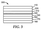
別の例示的な実施形態を図3に模式的に示す。ソーラーミラーフィルム300は、プレマスク層110、MOF耐候性層220、コンプライアンス層310(例えば、ブチルアクリレートを含む)、薄いスパッタコーティンされた結合層140、反射層150(例えば、銀等の反射金属を含む)、耐食性層160(例えば、銅等の金属を含む)、接着剤層170、及びライナー180を含む。
Another exemplary embodiment is shown schematically in FIG. The
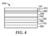
別の例示的な実施形態を図4に模式的に示す。ソーラーミラーフィルム400は、プレマスク層110、PMMA層410、接着剤層420、MOF耐候性層220、薄いスパッタコーティンされた結合層140、反射層150(例えば、銀等の反射金属を含む)、耐食性層160(例えば、銅等の金属を含む)、接着剤層170、及びライナー180を含む。この実施形態の幾つかの実施は、図3に模式的に示すように、また以下に記載するように、コンプライアンス層も含む。
Another exemplary embodiment is shown schematically in FIG. The
別の例示的な実施形態を図5に模式的に示す。ソーラーミラーフィルム500は、プレマスク層110、コンプライアンス層310、MOF耐候性層220、薄いスパッタコーティンされた結合層140、反射層150(例えば、銀等の反射金属を含む)、耐食性層160(例えば、銅等の金属を含む)、接着剤層170、及びライナー180を含む。
Another exemplary embodiment is shown schematically in FIG. The
明瞭にする目的のために、図1〜5に示す及び本明細書に記載する様々な実施形態における全ての層は、MOF層及び反射層を除いて任意である。一般的に本明細書に記載される種類のソーラーミラーフィルムに含まれ得る各層について、以下に詳細に論じる。 For clarity purposes, all layers in the various embodiments shown in FIGS. 1-5 and described herein are optional except the MOF layer and the reflective layer. Each layer that may be included in a solar mirror film of the type generally described herein is discussed in detail below.
プレマスク層
プレマスク層は、任意である。存在する場合、プレマスクは、取り扱い、積層、及び設置中に耐候性層を保護する。次いで、このような構成は、輸送、保管及び消費者使用のために便利にパッケージ化することができる。幾つかの実施形態では、プレマスクは、屋外設置中に作業者を保護するために不透明である。幾つかの実施形態では、プレマスクは、欠陥を点検できるように透明である。任意の公知のプレマスクを用いることができる。1つの例示的な市販のプレマスクは、Tredegar of Richmond,Virginiaによって販売されているForceField(登録商標)1035である。
Premask Layer The premask layer is optional. When present, the premask protects the weathering layer during handling, lamination and installation. Such a configuration can then be conveniently packaged for shipping, storage and consumer use. In some embodiments, the premask is opaque to protect workers during outdoor installations. In some embodiments, the premask is transparent so that defects can be inspected. Any known premask can be used. One exemplary commercial premask is ForceField® 1035 sold by Tredegar of Richmond, Virginia.
多層光学フィルム層
本開示の例示的な多層光学フィルムは、例えば、「Apparatus for Making Multilayer Optical Films」という名称の米国特許第6,783,349号、「Method for Making Multilayer Optical Films」という名称の米国特許第6,827,886号、並びに「Solar Concentrating Mirror」という名称の国際公開第2009/140493号及び「Multi−layer Optical Films」という名称の国際公開第2011/062836号(これらは全て、参照によりその全文が本明細書に援用される)に開示されている装置及び方法を用いて調製してよい。国際公開第2009/140493号には、PMMA/PVDFスキン層が記載されている。本開示の例示的な多層光学フィルムとともに用いるのに好適な更なる層又はコーティングの例は、例えば、両方とも「Multilayer Polymer Film with Additional Coatings or Layers」という名称の米国特許第6,368,699号及び同第6,459,514号(これらは両方、参照することによりその全文が本明細書に援用される)に記載されている。
Multi-Layer Optical Film Layers An exemplary multi-layer optical film of the present disclosure is, for example, US Pat. Patent No. 6,827,886 and International Publication No. 2009/140493 entitled "Solar Concentrating Mirror" and International Publication No. 2011/062836 entitled "Multi-layer Optical Films", all of which are by reference. It may be prepared using the devices and methods disclosed herein in their entirety). WO 2009/140493 describes a PMMA/PVDF skin layer. Examples of additional layers or coatings suitable for use with the exemplary multilayer optical films of the present disclosure are, for example, US Pat. No. 6,368,699, both entitled “Multilayer Polymer Film with Additional Coatings or Layers”. And 6,459,514, both of which are incorporated herein by reference in their entireties.
幾つかの実施形態では、耐候性MOF層は、高反射率(>90%)のスペクトル領域及び高透過率(>90%)の他のスペクトル領域を有し得る。幾つかの実施形態では、耐候性層は、太陽スペクトルの一部に対する高光透過率、並びに低曇り度及び黄変、良好な耐候性、良好な接着力、取り扱い及び洗浄中の耐引っ掻き性及び耐亀裂性、並びに、例えば、小型電子ディスプレー及び/又は太陽エネルギー用途で基材として用いられるとき、フィルムの一方又は両方の主表面に適用される他の層(例えば、他の(コ)ポリマー層、金属酸化物層、及び金属層)に対する良好な接着力を提供する。 In some embodiments, the weatherable MOF layer can have high reflectance (>90%) spectral regions and high transmission (>90%) other spectral regions. In some embodiments, the weatherable layer has a high light transmission for a portion of the solar spectrum and low haze and yellowing, good weatherability, good adhesion, scratch resistance and resistance during handling and washing. Crackability and other layers applied to the major surface of one or both of the films (eg, other (co)polymer layers, when used as a substrate in, for example, small electronic display and/or solar energy applications, Provide good adhesion to the metal oxide layer and the metal layer).
ソーラーミラーフィルム構造物に多層光学フィルムを含むことは、幾つかの実施形態では、インラインプロセスとして導入することができる。 Including a multi-layer optical film in the solar mirror film structure can, in some embodiments, be introduced as an in-line process.
ソーラーミラーフィルムに多層光学フィルムを含むことにより、様々な利点が付与される。多層光学フィルムは、従来技術の耐候性層の吸湿膨張係数と反射層の吸湿膨張係数の間の吸湿膨張係数を有する。幾つかの実施形態では、多層光学フィルムは、RHパーセント当たり30ppm未満である吸湿膨張係数を有する。幾つかの実施形態では、多層光学フィルムは、パーセント相対湿度当たり約10ppm〜パーセント相対湿度当たり約25ppmの吸湿膨張係数を有する。幾つかの実施形態では、多層光学フィルムは、パーセント相対湿度当たり約15ppm〜パーセント相対湿度当たり約20ppmの吸湿膨張係数を有する。 The inclusion of multilayer optical films in solar mirror films provides various advantages. The multilayer optical film has a hygroscopic expansion coefficient between that of the prior art weather resistant layer and that of the reflective layer. In some embodiments, the multilayer optical film has a hygroscopic expansion coefficient that is less than 30 ppm per RH percent. In some embodiments, the multilayer optical film has a coefficient of hygroscopic expansion of from about 10 ppm per percent relative humidity to about 25 ppm per percent relative humidity. In some embodiments, the multilayer optical film has a coefficient of hygroscopic expansion of from about 15 ppm per percent relative humidity to about 20 ppm per percent relative humidity.
従来技術の耐候性フィルムは、RHパーセント当たり少なくとも約30ppmの吸湿膨張係数を有する。幾つかの実施形態では、多層光学フィルムの吸湿膨張係数は、従来技術の耐候性層の吸湿膨張係数の約75%〜約25%である。幾つかの実施形態では、多層光学フィルムの吸湿膨張係数は、従来技術の耐候性層の吸湿膨張係数の約70%〜約30%である。幾つかの実施形態では、多層光学フィルムの吸湿膨張係数は、従来技術の耐候性層の吸湿膨張係数の約60%〜約40%である。 Prior art weatherable films have a coefficient of hygroscopic expansion of at least about 30 ppm per percent RH. In some embodiments, the coefficient of hygroscopic expansion of the multilayer optical film is about 75% to about 25% of the coefficient of hygroscopic expansion of prior art weather resistant layers. In some embodiments, the coefficient of hygroscopic expansion of the multilayer optical film is from about 70% to about 30% of the coefficient of hygroscopic expansion of prior art weather resistant layers. In some embodiments, the hygroscopic expansion coefficient of the multilayer optical film is about 60% to about 40% of the hygroscopic expansion coefficient of the prior art weather resistant layer.
結合層
幾つかの実施形態では、結合層は、酸化アルミニウム、酸化銅、二酸化チタン、二酸化ケイ素、及びこれらの組合せ等の金属酸化物を含む。結合層として、二酸化チタンは、乾燥剥離及び湿潤剥離試験において、驚くほど高い層間剥離耐性をもたらすことが見出されている。金属酸化物結合層の更なる選択肢及び利点は、参照することにより本明細書に援用される米国特許第5,361,172号(Schisselら)に記載されている。
Tie Layer In some embodiments, the tie layer comprises a metal oxide such as aluminum oxide, copper oxide, titanium dioxide, silicon dioxide, and combinations thereof. As a tie layer, titanium dioxide has been found to provide surprisingly high delamination resistance in dry and wet peel tests. Further options and advantages of metal oxide tie layers are described in US Pat. No. 5,361,172 (Schissel et al.), which is hereby incorporated by reference.
前述の例示的な実施形態のいずれかでは、結合層は、500マイクロメートル以下の厚さを有する。幾つかの実施形態では、結合層は、約0.1マイクロメートル〜約5マイクロメートルの厚さを有する。幾つかの実施形態では、結合層は、少なくとも0.1ナノメートル、少なくとも0.25ナノメートル、少なくとも0.5ナノメートル、又は少なくとも1ナノメートルの合計厚さを有することが好ましい。幾つかの実施形態では、結合層は、2ナノメートル以下、5ナノメートル以下、7ナノメートル以下、又は10ナノメートル以下の合計厚さを有することが好ましい。 In any of the foregoing exemplary embodiments, the tie layer has a thickness of 500 micrometers or less. In some embodiments, the tie layer has a thickness of about 0.1 micrometer to about 5 micrometers. In some embodiments, the tie layer preferably has a total thickness of at least 0.1 nanometers, at least 0.25 nanometers, at least 0.5 nanometers, or at least 1 nanometer. In some embodiments, the tie layer preferably has a total thickness of 2 nanometers or less, 5 nanometers or less, 7 nanometers or less, or 10 nanometers or less.
コンプライアンス層
幾つかの実施形態では、ソーラーミラーフィルムは、コンプライアンス層を含む。コンプライアンス層は、好ましくは、周囲温度で非粘着性である。幾つかの実施形態では、コンプライアンス層は、ポリ(メチルメタクリレート)と、それぞれメタクリレート、アクリレート、スチレン、又はこれらの組み合わせを含む第1のモノエチレン性不飽和モノマーから誘導される少なくとも2つのエンドブロックポリマー単位であって、各エンドブロックが、少なくとも摂氏50度のガラス転移温度を有するエンドブロックポリマー単位、及びメタクリレート、アクリレート、ビニルエステル、又はこれらの組み合わせを含む第2のモノエチレン性不飽和モノマーから誘導される少なくとも1つのミッドブロックポリマー単位であって、各ミッドブロックが、摂氏20度以下のガラス転移温度を有するミッドブロックポリマー単位を有する、第1のブロックコポリマーと、を含む。
Compliance Layer In some embodiments, the solar mirror film comprises a compliance layer. The compliance layer is preferably non-tacky at ambient temperature. In some embodiments, the compliance layer comprises poly(methylmethacrylate) and at least two endblock polymers derived from a first monoethylenically unsaturated monomer each comprising methacrylate, acrylate, styrene, or combinations thereof. Units derived from an endblock polymer unit, each endblock having a glass transition temperature of at least 50 degrees Celsius, and a second monoethylenically unsaturated monomer comprising a methacrylate, an acrylate, a vinyl ester, or combinations thereof. At least one midblock polymer unit, wherein each midblock comprises a midblock polymer unit having a glass transition temperature of 20 degrees Celsius or less.
あるいは、幾つかの実施形態では、コンプライアンス層は、ブロックコポリマー/ホモポリマーブレンドを含む。例えば、コンプライアンス層は、A又はBブロックのいずれかに可溶性であるホモポリマーとブレンドしたA−B−Aトリブロックコポリマーを含み得る。任意で、ホモポリマーは、A又はBブロックのいずれかと同一のポリマー単位を有する。1つ以上のホモポリマーのブロックコポリマー組成物への添加は、1つ又は両方のブロックを可塑化又は硬化するために有利に利用することができる。好ましい実施形態では、ブロックコポリマーは、ポリ(メチルメタクリレート)Aブロック及びポリ(ブチルアクリレート)Bブロックを含み、ポリ(メチルメタクリレート)ホモポリマーとブレンドされる。 Alternatively, in some embodiments, the compliance layer comprises a block copolymer/homopolymer blend. For example, the compliance layer can include an ABA triblock copolymer blended with a homopolymer that is soluble in either the A or B block. Optionally, the homopolymer has the same polymer units as either A or B blocks. Addition of one or more homopolymers to the block copolymer composition can be advantageously utilized to plasticize or cure one or both blocks. In a preferred embodiment, the block copolymer comprises poly(methyl methacrylate) A blocks and poly(butyl acrylate) B blocks and is blended with poly(methyl methacrylate) homopolymer.
有利なことに、ポリ(メチルメタクリレート)ホモポリマーをポリ(メチルメタクリレート)−ポリ(ブチルアクリレート)ブロックコポリマーとブレンドすることにより、硬度を、望ましい用途に合わせて調節することが可能になる。更なる有利な点として、ポリ(メチルメタクリレート)とのブレンドは、組成物全体の透明度又は加工性を有意に低下させることなく硬度に対する制御を提供する。好ましくは、ホモポリマー/ブロックコポリマーブレンドは、ブレンドの総重量に基づいて少なくとも30パーセント、少なくとも40パーセント、又は少なくとも50パーセントの総ポリ(メチルメタクリレート)組成物を有する。好ましくは、ホモポリマー/ブロックコポリマーブレンドは、ブレンドの総重量に基づいて95%以下、90%以下、又は80%以下の総ポリ(メチルメタクリレート)組成物を有する。 Advantageously, blending the poly(methylmethacrylate) homopolymer with the poly(methylmethacrylate)-poly(butylacrylate) block copolymer allows the hardness to be adjusted for the desired application. As a further advantage, the blend with poly(methylmethacrylate) provides control over hardness without significantly reducing the clarity or processability of the overall composition. Preferably, the homopolymer/block copolymer blend has at least 30 percent, at least 40 percent, or at least 50 percent total poly(methyl methacrylate) composition, based on the total weight of the blend. Preferably, the homopolymer/block copolymer blend has a total poly(methylmethacrylate) composition of 95% or less, 90% or less, or 80% or less based on the total weight of the blend.
特に好適な非粘着性ブロックコポリマーとしては、ポリ(メチルメタクリレート)−ポリ(n−ブチルアクリレート)−ポリ(メチルメタクリレート)(25:50:25)トリブロックコポリマーが挙げられる。これら材料は、Kuraray Co.,LTDから商品名LA POLYMERとして既に入手可能である。 Particularly suitable non-stick block copolymers include poly(methyl methacrylate)-poly(n-butyl acrylate)-poly(methyl methacrylate) (25:50:25) triblock copolymers. These materials are commercially available from Kuraray Co. , LTD. is already available under the trade name LA POLYMER.
任意で、ブロックコポリマーを好適な紫外線吸収剤と組み合わせて、安定性を高めることができる。幾つかの実施形態では、ブロックコポリマーは、紫外線吸収剤を含有する。幾つかの実施形態では、ブロックコポリマーは、ブロックコポリマー及び紫外線吸収剤の総重量に基づいて0.5重量パーセント〜3.0重量パーセントの範囲の量の紫外線吸収剤を含有する。しかし、ブロックコポリマーは、紫外線吸収剤を含有する必要はないことに留意されたい。紫外線吸収剤は表面から分離し、隣接層に対する接着に干渉することがあるので、紫外線吸収剤を全く含まない組成物を使用することは有利であり得る。 The block copolymer can optionally be combined with a suitable UV absorber to enhance stability. In some embodiments, the block copolymer contains a UV absorber. In some embodiments, the block copolymer contains an amount of UV absorber ranging from 0.5 weight percent to 3.0 weight percent, based on the total weight of the block copolymer and UV absorber. However, it should be noted that the block copolymer need not contain a UV absorber. It may be advantageous to use a composition that does not contain any UV absorber, as the UV absorber may separate from the surface and interfere with adhesion to adjacent layers.
幾つかの実施形態では、ブロックコポリマーは、コンプライアンス層の弾性率を調整するために1つ以上のナノフィラーと合わせてよい。例えば、二酸化ケイ素又は二酸化ジルコニウム等のナノフィラーをブロックコポリマーに均一に分散させて、ソーラーミラーフィルムの全体的な剛性又は硬度を高めることができる。好ましい実施形態では、ナノフィラーは、ポリマーマトリックスと相溶性になるよう表面改質される。 In some embodiments, the block copolymer may be combined with one or more nanofillers to tailor the elastic modulus of the compliance layer. For example, nanofillers such as silicon dioxide or zirconium dioxide can be evenly dispersed in the block copolymer to increase the overall stiffness or hardness of the solar mirror film. In a preferred embodiment, the nanofillers are surface modified to be compatible with the polymer matrix.
幾つかの実施形態では、コンプライアンス層は、比較的高いTgを有する第1のポリマー単位と、比較的低いTgを有する第2のポリマー単位とを有するランダムコポリマーを含む。この実施形態では、第1のポリマー単位は、メタクリレート、アクリレート、スチレン、又はこれらの組み合わせを含む第1のモノエチレン性不飽和モノマーから誘導され、且つ少なくとも摂氏50度のガラス転移温度を有し、第2のポリマー単位は、メタクリレート、アクリレート、ビニルエステル、又はこれらの組み合わせを含む第2のモノエチレン性不飽和モノマーから誘導され、且つ摂氏20度以下のガラス転移温度を有する。幾つかの好ましいランダムコポリマーでは、第1のポリマー単位は、メチルメタクリレートであり、第2のポリマー単位は、ブチルアクリレートである。ランダムコポリマーは、ランダムコポリマーの総重量に基づいて少なくとも50%、少なくとも60%、少なくとも70%、又は少なくとも80%のメチルメタクリレート組成物を有することが好ましい。ランダムコポリマーは、ランダムコポリマーの重量に基づいて最高80パーセント、最高85パーセント、最高90パーセント、又は最高95パーセントのメチルメタクリレート組成物を有することが更に好ましい。 In some embodiments, the compliance layer comprises a random copolymer having a first polymer unit with a relatively high T g and a second polymer unit with a relatively low T g . In this embodiment, the first polymeric unit is derived from a first monoethylenically unsaturated monomer comprising methacrylate, acrylate, styrene, or a combination thereof and has a glass transition temperature of at least 50 degrees Celsius. The second polymeric unit is derived from a second monoethylenically unsaturated monomer containing a methacrylate, an acrylate, a vinyl ester, or a combination thereof and has a glass transition temperature of 20 degrees Celsius or less. In some preferred random copolymers, the first polymer unit is methyl methacrylate and the second polymer unit is butyl acrylate. The random copolymer preferably has at least 50%, at least 60%, at least 70%, or at least 80% methyl methacrylate composition, based on the total weight of the random copolymer. More preferably, the random copolymer has up to 80 percent, up to 85 percent, up to 90 percent, or up to 95 percent of the methyl methacrylate composition based on the weight of the random copolymer.
幾つかの実施形態では、コンプライアンス層は、少なくとも10マイクロメートル、少なくとも50マイクロメートル、又は少なくとも60マイクロメートルの厚さを有する。更に、幾つかの実施形態では、コンプライアンス層は、200マイクロメートル以下、150マイクロメートル以下、又は100マイクロメートル以下の厚さを有する。幾つかの実施形態では、コンプライアンス層は、5マイクロメート以下の厚さを有する。幾つかのこのような実施形態では、コンプライアンス層は、0.1マイクロメートル〜3マイクロメートルの厚さを有する。 In some embodiments, the compliance layer has a thickness of at least 10 micrometers, at least 50 micrometers, or at least 60 micrometers. Further, in some embodiments, the compliance layer has a thickness of 200 micrometers or less, 150 micrometers or less, or 100 micrometers or less. In some embodiments, the compliance layer has a thickness of 5 micrometers or less. In some such embodiments, the compliance layer has a thickness of 0.1 micrometer to 3 micrometers.
反射層
本明細書に記載するソーラーミラーフィルムは、1層以上の反射層を含む。高度の反射率を提供することに加えて、反射層は、製造の柔軟性を提供することができる。任意で、反射層は、比較的薄い有機結合層又は無機結合層に適用することができ、この結合層が耐候性層上に配置される。
Reflective Layer The solar mirror films described herein include one or more reflective layers. In addition to providing a high degree of reflectivity, the reflective layer can provide manufacturing flexibility. Optionally, the reflective layer can be applied to a relatively thin organic or inorganic tie layer, which tie layer is disposed on the weathering layer.
幾つかの実施形態では、反射層は、鏡面反射性である滑らかな反射金属層を有する。本明細書で使用するとき、用語「鏡面」は、入射光の方向と出射光の方向とが表面垂線に対して同じ角度を形成する、鏡のような光の反射を誘導する表面を指す。この目的のために任意の反射金属を使用することができるが、好ましい金属としては、銀、金、アルミニウム、銅、ニッケル、及びチタンが挙げられる。幾つかの実施形態では、反射層は、元素銀を含む。 In some embodiments, the reflective layer comprises a smooth reflective metal layer that is specular. As used herein, the term "mirror surface" refers to a surface that induces a specular reflection of light such that the direction of incident light and the direction of emitted light form the same angle with respect to the surface normal. Although any reflective metal can be used for this purpose, preferred metals include silver, gold, aluminum, copper, nickel, and titanium. In some embodiments, the reflective layer comprises elemental silver.
反射層は、RHパーセント当たり約0ppmの吸湿膨張係数を有する。幾つかの実施形態では、反射層は、RHパーセント当たり約0ppm〜RHパーセント当たり約3ppmの吸湿膨張係数を有する。 The reflective layer has a coefficient of hygroscopic expansion of about 0 ppm per RH percent. In some embodiments, the reflective layer has a coefficient of hygroscopic expansion of about 0 ppm per RH percent to about 3 ppm per RH percent.
反射層は、耐候性層の主表面全体にわたって延在する必要はない。必要に応じて、反射層が耐候性層の所定の部分のみに適用されるように、耐候性層は、蒸着プロセス中マスクされてもよい。 The reflective layer need not extend over the entire major surface of the weather resistant layer. If desired, the weatherable layer may be masked during the deposition process so that the reflective layer is applied only to certain portions of the weatherable layer.
多層光学フィルム又は耐候性層上への反射層のパターン化蒸着も可能である。反射層にパターンを生成する例示的な方法は、例えば、案件番号69678US002、69677US002、及び69681US002(全て本出願人に譲渡され、全文が本明細書に援用される)に記載されている。 Patterned deposition of a reflective layer on a multilayer optical film or weather resistant layer is also possible. Exemplary methods of generating a pattern in a reflective layer are described, for example, in Case Nos. 69678US002, 69677US002, and 69681US002, all assigned to Applicants and incorporated herein in their entirety.
金属のポリマーへの適用は、例えば、スパッタコーティングを介する物理蒸着、e−ビーム又は熱的方法を介する蒸発、イオンアシストe−ビーム蒸発、電気めっき、スプレー塗装、真空蒸着、及びこれらの組み合わせを含む多数のコーティング方法を用いて行うことができる。金属化プロセスは、用いられるポリマー及び金属、コスト、並びに多くの他の技術的及び実用的要因に基づいて選択される。 Applications of metals to polymers include, for example, physical vapor deposition via sputter coating, evaporation via e-beam or thermal methods, ion assisted e-beam evaporation, electroplating, spray coating, vacuum evaporation, and combinations thereof. A number of coating methods can be used. The metallization process is selected based on the polymer and metal used, cost, and many other technical and practical factors.
金属の物理蒸着(PVD)は、幾つかの用途において非常に一般的であるが、その理由は、清浄な界面上に最も純度の高い金属を提供するためである。この技法では、ターゲットの原子は、基材上に衝突して薄いフィルムを形成することができるように、高エネルギー粒子ボンバードメントによって発射される。スパッタ蒸着に使用される高エネルギー粒子は、グロー放電によって、又は、例えば、電磁場をアルゴンガスに印加することによって生成される自己保持性プラズマによって生成される。 Physical vapor deposition (PVD) of metals is very common in some applications because it provides the purest metal on a clean interface. In this technique, target atoms are launched by a high energy particle bombardment so that they can impinge on a substrate to form a thin film. The high-energy particles used in sputter deposition are generated by glow discharge or by self-sustaining plasma, for example generated by applying an electromagnetic field to argon gas.
1つの例示的な方法において、蒸着プロセスは、耐候性層上に好適な層厚さの反射層を構築するのに十分な持続時間継続され、これによって反射層を形成する。 In one exemplary method, the deposition process is continued for a duration sufficient to build a reflective layer of suitable layer thickness on the weatherable layer, thereby forming the reflective layer.
反射層は、好ましくは、望ましい太陽光スペクトル量を反射するのに十分な厚さである。好ましい厚さは、反射層の組成によって変動してよい。幾つかの例示的な実施形態では、反射層は、銀、アルミニウム、銅、及び金等の金属について約75ナノメートル〜約100ナノメートルの厚さを有する。図には示されていないが、2層以上の反射層を使用してもよい。 The reflective layer is preferably thick enough to reflect the desired amount of the solar spectrum. The preferred thickness may vary depending on the composition of the reflective layer. In some exemplary embodiments, the reflective layer has a thickness of about 75 nanometers to about 100 nanometers for metals such as silver, aluminum, copper, and gold. Although not shown in the figure, two or more reflective layers may be used.
幾つかの実施形態では、反射層は、500ナノメートル以下の厚さを有する。幾つかの実施形態では、反射層は、80nm〜250nmの厚さを有する。幾つかの実施形態では、反射層は、少なくとも25ナノメートル、少なくとも50ナノメートル、少なくとも75ナノメートル、少なくとも90ナノメートル、又は少なくとも100ナノメートルの厚さを有する。更に、幾つかの実施形態において、反射層が、100ナノメートル以下、110ナノメートル以下、125ナノメートル以下、150ナノメートル以下、200ナノメートル以下、300ナノメートル以下、400ナノメートル以下、又は500ナノメートル以下の厚さを有する。 In some embodiments, the reflective layer has a thickness of 500 nanometers or less. In some embodiments, the reflective layer has a thickness of 80 nm to 250 nm. In some embodiments, the reflective layer has a thickness of at least 25 nanometers, at least 50 nanometers, at least 75 nanometers, at least 90 nanometers, or at least 100 nanometers. Further, in some embodiments, the reflective layer is 100 nm or less, 110 nm or less, 125 nm or less, 150 nm or less, 200 nm or less, 300 nm or less, 400 nm or less, or 500 nm or less. It has a thickness of nanometers or less.
耐食性層
耐食性層は、任意である。含まれる場合、耐食性層は、例えば、元素銅を含んでよい。犠牲陽極として作用する銅層を使用することで、耐食性及び屋外耐候性の強化された反射物品を提供することができる。別のアプローチとして、インコネル(鉄−ニッケル合金)等の比較的不活性な合金を使用することもできる。
Corrosion resistant layer The corrosion resistant layer is optional. If included, the corrosion resistant layer may include, for example, elemental copper. The use of a copper layer that acts as a sacrificial anode can provide a reflective article with enhanced corrosion resistance and outdoor weatherability. Alternatively, a relatively inert alloy such as Inconel (iron-nickel alloy) can be used.
耐食性層は、好ましくは、所望の量の耐食性を提供するのに十分な厚さである。好ましい厚さは、耐食性層の組成によって変動してよい。幾つかの例示的な実施形態では、耐食性層は、約75ナノメートル〜約100ナノメートルの厚さである。他の実施形態では、耐食性層は、約20ナノメートル〜約30ナノメートルの厚さである。図には示されていないが、2層以上の耐食性層を用いてもよい。 The corrosion resistant layer is preferably thick enough to provide the desired amount of corrosion resistance. The preferred thickness may vary depending on the composition of the corrosion resistant layer. In some exemplary embodiments, the corrosion resistant layer is about 75 nanometers to about 100 nanometers thick. In other embodiments, the corrosion resistant layer is about 20 nanometers to about 30 nanometers thick. Although not shown in the figure, two or more corrosion resistant layers may be used.
幾つかの実施形態では、耐食性層は、500ナノメートル以下の厚さを有する。幾つかの実施形態では、耐食性層は、80nm〜250nmの厚さを有する。幾つかの実施形態では、耐食性層は、少なくとも25ナノメートル、少なくとも50ナノメートル、少なくとも75ナノメートル、少なくとも90ナノメートル、又は少なくとも100ナノメートルの厚さを有する。更に、幾つかの実施形態では、耐食性層は、100ナノメートル以下、110ナノメートル以下、125ナノメートル以下、150ナノメートル以下、200ナノメートル以下、300ナノメートル以下、400ナノメートル以下、又は500ナノメートル以下の厚さを有する。 In some embodiments, the corrosion resistant layer has a thickness of 500 nanometers or less. In some embodiments, the corrosion resistant layer has a thickness of 80 nm to 250 nm. In some embodiments, the corrosion resistant layer has a thickness of at least 25 nanometers, at least 50 nanometers, at least 75 nanometers, at least 90 nanometers, or at least 100 nanometers. Further, in some embodiments, the corrosion resistant layer is 100 nanometers or less, 110 nanometers or less, 125 nanometers or less, 150 nanometers or less, 200 nanometers or less, 300 nanometers or less, 400 nanometers or less, or 500 nanometers or less. It has a thickness of nanometers or less.
接着剤層
接着剤層は、任意である。存在する場合、接着剤層は、多層構造物を基材(図示されない)に接着させる。幾つかの実施形態では、接着剤は、感圧接着剤である。本明細書で使用するとき、用語「感圧性接着剤」は、強力且つ持続性の粘着性、指圧以下での基材への接着性、及び基材から除去可能な十分な凝集力を示す接着剤を指す。例示的な感圧性接着剤としては、参照することにより本明細書に援用される国際公開第2009/146227号(Josephら)に記載されているものが挙げられる。
Adhesive Layer The adhesive layer is optional. When present, the adhesive layer adheres the multilayer structure to the substrate (not shown). In some embodiments, the adhesive is a pressure sensitive adhesive. As used herein, the term "pressure sensitive adhesive" means a strong and persistent tack, adhesion to a substrate under finger pressure, and adhesion that exhibits sufficient cohesive strength to be removed from the substrate. Refers to the agent. Exemplary pressure sensitive adhesives include those described in WO 2009/146227 (Joseph et al.), which is incorporated herein by reference.
ライナー
ライナーは、任意である。存在する場合、ライナーは、接着剤を保護し、ソーラーミラーフィルムを別の基材に移動させることができる。次いで、このような構成を、輸送、保管、及び消費者使用のために便利にパッケージ化してよい。幾つかの実施形態では、ライナーは、剥離ライナーである。幾つかの実施形態では、ライナーは、シリコーンコーティングされた剥離ライナーである。
Liner The liner is optional. When present, the liner protects the adhesive and can transfer the solar mirror film to another substrate. Such configurations may then be conveniently packaged for shipping, storage, and consumer use. In some embodiments, the liner is a release liner. In some embodiments, the liner is a silicone coated release liner.
基材
本明細書に記載するフィルムは、ライナー180(存在する場合)を除去し、基材に隣接して接着剤層170(存在する場合)を配置することによって、基材に適用することができる。次いで、プレマスク層110(存在する場合)を除去して、耐候性層120を太陽光に曝露する。好適な基材は概ね、特定の特性を共有している。最も重要なことに、基材は、十分に剛性でなければならない。第2に、基材は、基材の質感が接着剤/金属/ポリマー積層体を通って伝わることのないよう、十分に滑らかでなければならない。これは、次の理由から有利である:(1)光学的に正確な鏡を可能にする、(2)金属反射層を腐食させたり接着剤を劣化させたりする可能性のある反応性種の侵入経路を排除することによって、金属反射層の物理的一体性を維持する、及び(3)反射フィルム−基材積層体内の応力密度を制御及び規定する。第3に、基材は、好ましくは、腐食を防ぐため、反射鏡積層体に対して非反応性である。第4に、基材は、好ましくは、接着剤が耐久的に接着する表面を有する。
Substrates The films described herein may be applied to a substrate by removing the liner 180 (if present) and placing the adhesive layer 170 (if present) adjacent to the substrate. it can. The premask layer 110 (if present) is then removed and the
反射フィルム用の例示的な基材と、それに関連する選択肢及び利点は、国際公開第04114419号(Schripsema)、同第03022578号(Johnstonら)、米国特許公開第2010/0186336号(Valenteら)及び同第2009/0101195号(Reynoldsら)、並びに米国特許第7,343,913号(Neidermeyer)に記載されている。例えば、物品は、同時係属の同一出願人による米国仮出願第13/393,879号(Cosgroveら)に記載の通り、多くのミラーパネルアセンブリのうちの1つに含まれ得る。他の例示的な基材としては、金属(例えば、アルミニウム)、鋼、ガラス、又は複合材が挙げられる。 Exemplary substrates for reflective films and the options and advantages associated therewith are described in WO04114419 (Schripsema), WO03022578 (Johnston et al.), US Patent Publication No. 2010/0186336 (Valente et al.) and No. 2009/0101195 (Reynolds et al.), and US Pat. No. 7,343,913 (Neidermeyer). For example, the article may be included in one of many mirror panel assemblies as described in co-pending and commonly-assigned US Provisional Application No. 13/393,879 (Cosgrove et al.). Other exemplary substrates include metals (eg, aluminum), steel, glass, or composites.
当業者は、本明細書に記載する実施形態が、更なる材料又は層を含んでもよいことを理解する。例えば、幾つかの実施形態は、本出願人に譲渡され、参照することによりその全文が本明細書に援用される米国特許出願第69682US002に記載のように、コンプライアント層を含んでもよい。幾つかの実施形態は、本出願人に譲渡され、参照することによりその全文が本明細書に援用される米国特許出願第69678US002に記載のように、ソーラーミラーフィルムの縁部領域に銀を少量しか有しない又は全く有しなくてよい。 One of ordinary skill in the art will appreciate that the embodiments described herein may include additional materials or layers. For example, some embodiments may include a compliant layer, as described in US Patent Application No. 69682US002, which is assigned to the applicant and is hereby incorporated by reference in its entirety. Some embodiments assign a small amount of silver to the edge regions of the solar mirror film as described in US Patent Application No. 69678US002, which is assigned to the Applicant and incorporated herein by reference in its entirety. It may or may not have at all.
本開示の利点及び実施形態を以降の実施例によって更に例示するが、これら実施例において列挙される特定の材料及びそれらの量、並びに他の条件及び詳細は、本発明を不当に制限するように解釈されるべきではない。これらの実施例は単にあくまで例示を目的としたものであり、添付した「特許請求の範囲」に限定することを意味するものではない。更に、本開示の広範囲で示す数値的範囲及びパラメータは、近似値であるにも関わらず、具体的な実施例に記載される数値は可能な限り正確に報告する。しかしながら、いずれの数値も、それらのそれぞれの試験測定値に見られる標準偏差から必然的に生じる特定の誤差を本来有している。少なくとも特許請求の範囲への均等論の適用を制限する試みとしてではなく、各数値パラメータは、少なくとも、報告された有効数字の数を考慮して、通常の四捨五入を適用することによって解釈されなければならない。また、これらの実施例では、全ての百分率、比率、及び比は、特に断らない限り重量による。 The advantages and embodiments of the present disclosure are further illustrated by the following examples, in which the particular materials and their amounts recited in these examples, as well as other conditions and details, unduly limit the invention. It should not be interpreted. These examples are merely for purposes of illustration and are not meant to be limited to the appended claims. Further, the numerical ranges and parameters set forth extensively in this disclosure are approximations, but the numerical values set forth in the specific examples report as accurately as possible. However, any numerical value inherently has certain errors necessarily resulting from the standard deviation found in their respective test measurements. At least as an attempt to limit the application of the doctrine of equivalents to the claims, each numerical parameter must be construed, at least in light of the number of significant figures reported, by applying ordinary rounding. I won't. Also, in these examples, all percentages, ratios, and ratios are by weight unless otherwise indicated.
試験方法:
吸湿膨張係数(CHE):吸湿膨張は、DMA−RHアクセサリー(TA Instrumentsから入手)と一体化している動的機械分析装置(DMA)モデル「Q800」、TA Instrumentsから入手)を用いて測定した。25℃の一定温度で約20%〜約80%の範囲の変動する相対湿度の勾配にわたって変位(m/m)を測定した。湿度変化によって引き起こされるサンプル寸法の変化を用いて、CHEを計算する。結果は、パーセント相対湿度(% RH)当たりの百万分率(ppm)で表す。
Test method:
Coefficient of Hygroscopic Expansion (CHE): The coefficient of hygroscopic expansion was measured using a dynamic mechanical analyzer (DMA) model "Q800", obtained from TA Instruments, integrated with a DMA-RH accessory (obtained from TA Instruments). The displacement (m/m) was measured over a gradient of varying relative humidity ranging from about 20% to about 80% at a constant temperature of 25°C. CHE is calculated using the change in sample size caused by the change in humidity. Results are expressed as parts per million (ppm) per percent relative humidity (% RH).
中性塩噴霧試験(NSS)
結果を様々な時間後の目視観測として報告することを除いて、ISO 9227:2006「Corrosion tests in artificial atmospheres−−Salt spray tests」に概説されている手順に従って、比較例及び実施例の腐食を評価した。
Neutral salt spray test (NSS)
Corrosion of comparative examples and examples was evaluated according to the procedure outlined in ISO 9227:2006 "Corrosion tests in artificial atmospheres--Salt spray tests", except that the results are reported as visual observations after various times. did.
比較例
銀金属化アクリルフィルム(「ECP−305+」、3M Company,St.Paul,MNによって製造)を提供した。このフィルムは、結合層140を含んでいないことを除いて、図1に示すフィルムと実質的に同じに見えた。銀金属化アクリルフィルムは、RHパーセント当たり30ppmのCHEを有していた。製品に含まれているPSAを用いて、塗装されているアルミニウム基材にECP−305+フィルムを積層した。剪断機を用いてサンプルを4”×4”(10.6cm×10.6cm)に切断した。上記NSSに従ってサンプルを耐候試験したところ、72時間未満でトンネリングを示すことが見出された。
Comparative Example A silver metallized acrylic film (“ECP-305+”, manufactured by 3M Company, St. Paul, MN) was provided. This film looked substantially the same as the film shown in FIG. 1 except that it did not include the
(実施例1)
多層光学フィルムを以下の通り調製した:第1及び第2のポリマー層を多層ポリマー溶融物マニホールドを通して共押出して、500〜50層の交互に重なった層を有する多層溶融流を作製することによって多層光学積層体(以下に記載)を調製した。また、それぞれ約4マイクロメートルの厚さを有する2層のスキン層を、光学層積層体の各側に保護層として共押出した。多層溶融流を冷却ロール上に流延して、多層キャストウェブを作製した。次いで、多層キャストウェブを、テンターオーブン内で約105℃の温度まで加熱し、その後3.8×3.8の延伸比に二軸配向させた。約100nmの厚さの銀反射層をフィルム基材上に蒸着させた。約80nmの厚さの銅層を銀層上にコーティングした。25マイクロメートルのアクリル接着剤を銅層上にコーティングした。得られた多層光学フィルムを、約0.5mmの厚さを有するエポキシコーティングされたアルミニウム基材に接着させた。剪断機を用いて積層サンプルを4”×4”(10.6cm×10.6cm)に切断した。
(Example 1)
A multilayer optical film was prepared as follows: multilayer by coextruding first and second polymer layers through a multilayer polymer melt manifold to create a multilayer melt stream having 500 to 50 alternating layers. An optical laminate (described below) was prepared. Also, two skin layers each having a thickness of about 4 micrometers were coextruded as protective layers on each side of the optical layer stack. The multilayer melt stream was cast onto a chill roll to make a multilayer cast web. The multilayer cast web was then heated in a tenter oven to a temperature of about 105° C. and then biaxially oriented to a draw ratio of 3.8×3.8. A silver reflective layer about 100 nm thick was deposited on the film substrate. A copper layer about 80 nm thick was coated on the silver layer. A 25 micrometer acrylic adhesive was coated on the copper layer. The resulting multilayer optical film was adhered to an epoxy coated aluminum substrate having a thickness of about 0.5 mm. Laminated samples were cut into 4" x 4" (10.6 cm x 10.6 cm) using a shears machine.
多層積層体の第1のポリマー層は、ポリエチレンテレフタレート(PET)(商品名「PET 9921」として入手、Eastman Chemical Companyにより販売)及び約10重量パーセント(重量%)で配合された紫外線吸収剤(商品名「SUKANO UV MASTERBATCH TA07−07」として入手、Sukano Polymers Corporation,Duncan,South Carolinaにより販売)を含む複屈折性層であった。第2のポリマー層は、ポリメチル(メタ)アクリレートのコポリマー(co−PMMA)(商品名「ATOGLAS 510A」として入手、Arkema,King of Prussia,Pennsylvaniaによって販売)を含んでいた。スキン層は、35%ポリフッ化ビニリデン(PVDF)(商品名「DYNEON PVDF 6008」として入手、3M Companyによって販売)及び65%ポリメチル(メタ)アクリレート(PMMA)(商品名「CP−82」として入手、Plaskolite,Columbus,Ohioによって販売)を含むポリマーブレンドを含んでおり、これは、2.5重量%の第2の紫外線吸収剤を含んでいた。 The first polymer layer of the multi-layer laminate is polyethylene terephthalate (PET) (available under the trade designation "PET 9921", sold by Eastman Chemical Company) and a UV absorber (commercial product) blended at about 10 weight percent (commercial weight). It was a birefringent layer containing the name “SUKANO UV MASTERBATCH TA07-07”, sold by Sukano Polymers Corporation, Duncan, South Carolina). The second polymer layer comprised a copolymer of polymethyl (meth)acrylate (co-PMMA) (obtained under the tradename "ATOGLAS 510A", sold by Arkema, King of Prussia, Pennsylvania). The skin layer is 35% polyvinylidene fluoride (PVDF) (obtained under the trade name "DYNION PVDF 6008", sold by 3M Company) and 65% polymethyl (meth)acrylate (PMMA) (obtained under the trade name "CP-82", Plaskolite, Columbus, Ohio)), which contained 2.5% by weight of a second UV absorber.
多層MOFフィルムの吸湿膨張を上記の通り測定したところ、RHパーセント当たり約15ppmであると測定された。 The hygroscopic expansion of the multilayer MOF film was measured as described above and was determined to be about 15 ppm per RH percent.
積層フィルムサンプルを上記の通り耐候試験したところ、1500時間後でもトンネリングを示さないことが見出された。 When the laminated film samples were as weathering above, it was found to show no tunneling even after 150 0 hours.
(実施例2)
多層光学フィルムを以下の通り調製した:第1及び第2のポリマー層を多層ポリマー溶融物マニホールドを通して共押出して、100〜50層の交互に重なった層を有する多層溶融流を作製することによって多層光学積層体(以下に記載)を調製した。また、それぞれ約4マイクロメートルの厚さを有する2層のスキン層を、光学層積層体の各側に保護層として共押出した。多層溶融流を冷却ロール上に流延して、多層キャストウェブを作製した。次いで、多層キャストウェブを、テンターオーブン内で約105℃の温度に加熱し、その後3.8×3.8の延伸比に二軸配向させた。約100nmの厚さの銀反射層をフィルム基材上に蒸着させてよい。約80nmの厚さの銅層を銀層上にコーティングしてよい。25マイクロメートルのアクリル接着剤を銅層上にコーティングしてよい。得られた多層光学フィルムを、約0.5mmの厚さを有するエポキシコーティングされたアルミニウム基材に接着させてよい。
(Example 2)
A multilayer optical film was prepared as follows: Multilayer by coextruding first and second polymer layers through a multilayer polymer melt manifold to create a multilayer melt stream having 100 to 50 alternating layers. An optical laminate (described below) was prepared. Also, two skin layers each having a thickness of about 4 micrometers were coextruded as protective layers on each side of the optical layer stack. The multilayer melt stream was cast onto a chill roll to make a multilayer cast web. The multilayer cast web was then heated in a tenter oven to a temperature of about 105° C. and then biaxially oriented to a draw ratio of 3.8×3.8. A silver reflective layer about 100 nm thick may be deposited on the film substrate. A copper layer about 80 nm thick may be coated on the silver layer. A 25 micrometer acrylic adhesive may be coated on the copper layer. The resulting multilayer optical film may be adhered to an epoxy coated aluminum substrate having a thickness of about 0.5 mm.
多層積層体の第1のポリマー層は、80重量%ポリメチル(メタ)アクリレート(PMMA)(商品名「CP−82」として入手、Plaskolite,Columbus,Ohioによって販売)及び20重量%ポリフッ化ビニリデン(PVDF)(商品名「DYNEON PVDF 6008」として入手、3M Companyによって販売)を含むポリマーブレンドを含む非複屈折性層であった。第2のポリマー層は、20重量%ポリメチル(メタ)アクリレート(PMMA)(商品名「CP−82」として入手、Plaskolite,Columbus,Ohioによって販売)及び80重量%ポリフッ化ビニリデン(PVDF)(商品名「DYNEON PVDF 6008」として入手、3M Companyによって販売)を含むポリマーブレンドを含んでいた。スキン層は、ポリフッ化ビニリデン(PVDF)(商品名「DYNEON PVDF 6008」として入手、3M Companyによって販売)、及びポリメチル(メタ)アクリレート(PMMA)(商品名「CP−82」として入手、Plaskolite,Columbus,Ohioによって販売)を含み、更に10重量%の第2の紫外線吸収剤(商品名「SUKANO UV MASTERBATCH TA11−10 MB03」として入手、Sukano Polymers Corporationによって販売)を含むポリマーブレンドを含んでいた。 The first polymer layer of the multilayer laminate was 80 wt% polymethyl (meth)acrylate (PMMA) (available under the trade designation "CP-82", sold by Plaskolite, Columbia, Ohio) and 20 wt% polyvinylidene fluoride (PVDF). ) (Obtained under the trade name “DYNEON PVDF 6008”, sold by 3M Company) was a non-birefringent layer comprising a polymer blend. The second polymer layer is 20% by weight polymethyl (meth)acrylate (PMMA) (available under the trade name "CP-82", sold by Plaskolite, Columbia, Ohio) and 80% by weight polyvinylidene fluoride (PVDF) (trade name). Obtained as "DYNEON PVDF 6008" and sold by 3M Company). The skin layer is polyvinylidene fluoride (PVDF) (obtained under the trade name "DYNEON PVDF 6008", sold by 3M Company), and polymethyl (meth)acrylate (PMMA) (obtained under the trade name "CP-82", Plaskolite, Columbus. , Ohio), and a polymer blend containing 10% by weight of a second UV absorber (obtained under the trade name "SUKANO UV MASTERBATCH TA11-10 MB03", sold by Sukano Polymers Corporation).
上記の通り測定した多層MOFフィルムの吸湿膨張は、RHパーセント当たり約15ppmであると予測される。上記の通り耐候試験したフィルムは、1500時間後にトンネリングを示すとは予測されない。 The hygroscopic expansion of the multilayer MOF film measured as described above is expected to be about 15 ppm per RH percent. Films weathered as described above are not expected to show tunneling after 1500 hours.
言及された全ての参照は、参照により本明細書に組み込まれる。 All references mentioned are incorporated herein by reference.
他に指示がない限り、本開示及び特許請求の範囲で使用される特徴の大きさ、量、物理特性を表わす数字は全て、どの場合においても用語「約」によって修飾されるものとして理解されるべきである。それ故に、そうでないことが示されない限り、前述の明細書及び添付の特許請求の範囲で示される数値パラメータは、当業者が本明細書で開示される教示内容を用いて、目標対象とする所望の特性に応じて、変化し得る近似値である。 Unless otherwise indicated, all numerical values indicating size, amount, physical properties of features used in this disclosure and claims are understood to be modified by the term "about" in each case. Should be. Therefore, unless otherwise indicated, the numerical parameters set forth in the foregoing description and appended claims are intended to be targeted by those skilled in the art using the teachings disclosed herein. It is an approximate value that can change according to the characteristics of.
本明細書及び添付の「特許請求の範囲」において使用するとき、単数形「a」、「an」、及び「the」は、その内容が明らかにそうでないことが示さないかぎりは複数の指示物を有する実施形態を包含する。本開示及び添付の特許請求の範囲において使用するとき、その内容について別段の明確な指示がない限り、「又は」という用語は概して、「及び/又は」を包含する意味で用いられる。 As used in this specification and the appended claims, the singular forms "a", "an", and "the" refer to plural referents unless the content clearly indicates otherwise. Including embodiments having As used in this disclosure and the appended claims, the term "or" is generally employed in its sense including "and/or" unless the content clearly dictates otherwise.
本出願では、以下の態様が提供される。
1. パーセント相対湿度当たり約30ppm未満の吸湿膨張係数を有する多層光学フィルム層と、反射層と、を含む、ソーラーミラーフィルム。
2. 前記多層光学フィルム層の吸湿膨張係数が、パーセント相対湿度当たり約25ppm〜パーセント相対湿度当たり約5ppmである、態様1に記載のソーラーミラーフィルム。
3. 前記反射層が、金属層である、態様1又は2に記載のソーラーミラーフィルム。
4. 前記反射層が、銀、金、アルミニウム、銅、ニッケル、及びチタンのうちの少なくとも1つを含む、態様1〜3のいずれか一項に記載のソーラーミラーフィルム。
5. 前記反射層が、パーセント相対湿度当たり0ppm〜パーセント相対湿度当たり3ppmの吸湿膨張係数を有する、態様1〜4のいずれか一項に記載のソーラーミラーフィルム。
6. 前記多層光学フィルム層と前記反射層との間に結合層を更に含む、態様1〜5のいずれか一項に記載のソーラーミラーフィルム。
7. 前記結合層が、二酸化チタンを含む、態様6に記載のソーラーミラーフィルム。
8. 前記多層光学フィルム層が、耐候性層である、態様1〜7のいずれか一項に記載のソーラーミラーフィルム。
9. 前記多層光学フィルム層に隣接する耐候性層を更に含む、態様1〜8のいずれか一項に記載のソーラーミラーフィルム。
10. 前記多層光学フィルム層が、380nm〜3,000nmの太陽放射波長域の一部にわたって少なくとも90%の平均放射反射率を示す、態様1〜9のいずれか一項に記載のソーラーミラーフィルム。
11. 前記多層光学フィルム層の吸湿膨張係数が、パーセント相対湿度当たり約10ppm〜パーセント相対湿度当たり約25ppmである、態様1〜10のいずれか一項に記載のソーラーミラーフィルム。
12. 前記多層光学フィルム層の吸湿膨張係数が、パーセント相対湿度当たり約15ppm〜パーセント相対湿度当たり約20ppmである、態様1〜11のいずれか一項に記載のソーラーミラーフィルム。
13. 前記多層光学フィルム層と前記反射層との間にコンプライアンス層を更に含む、態様1〜12のいずれか一項に記載のソーラーミラーフィルム。
14. 前記コンプライアンス層が、ブチルアクリレートを含む、態様13に記載のソーラーミラーフィルム。
15. 前記反射層に隣接する防食性層を更に含む、態様1〜14のいずれか一項に記載のソーラーミラーフィルム。
16. 前記防食性層が、銅及び不活性金属合金のうちの少なくとも1つを含む、態様15に記載のソーラーミラーフィルム。
17. 前記反射層に隣接する接着剤層を更に含む、態様1〜16のいずれか一項に記載のソーラーミラーフィルム。
18. 前記接着剤層が、感圧性接着剤を含む、態様17に記載のソーラーミラーフィルム。
19. 前記接着剤層が、前記反射層と基材との間に存在する、態様17又は18に記載のソーラーミラーフィルム。
20. 基材を更に含む、態様1〜19のいずれか一項に記載のソーラーミラーフィルム。
21. 反射体アセンブリに組み込まれる、態様1〜20のいずれか一項に記載のソーラーミラーフィルム。
22. PMMA及びPVDFを含む1層以上のスキン層を含む、態様1〜21のいずれか一項に記載のソーラーミラーフィルム。
23. PMMAとPVDFとのブレンドを含む1層以上の光学層を含む、態様1〜22のいずれか一項に記載のソーラーミラーフィルム。
24. 態様1〜23のいずれか一項に記載のソーラーミラーフィルムを含む、集光型光起電システム。
25. 態様1〜23のいずれか一項に記載のソーラーミラーフィルムを含む、集光型太陽光発電システム。
本開示の様々な実施形態及び実施が開示される。開示された実施形態は、例証するために提示されるもので、制限するためのものではない。上記の実施及び他の実施は以下の請求項の範囲内である。本開示が、開示されたもの以外の実施形態及び実施により実行され得ることは当業者には理解されよう。上記の実施形態及び実施例の詳細には、本発明の基礎をなす原理から逸脱することなく多くの変更を加えることができる点は当業者に認識されるであろう。本発明は、本明細書に記載される例示的な実施形態及び実施例によって不当に限定されるものではない点、また、こうした実施例及び実施形態はあくまで例示を目的として示されるにすぎないのであって、本発明の範囲は本明細書において以下に記載する「特許請求の範囲」によってのみ限定されるものである点は理解すべきである。更に、本発明に対する様々な改変及び変形が、本開示の趣旨及び範囲から逸脱することなく当業者にとって明らかとなろう。したがって、本出願の範囲は、以下の「特許請求の範囲」によってのみ定められるべきものである。
In the present application, the following aspects are provided.
1. A solar mirror film comprising a multilayer optical film layer having a coefficient of hygroscopic expansion of less than about 30 ppm per percent relative humidity and a reflective layer.
2. The solar mirror film of aspect 1, wherein the hygroscopic expansion coefficient of the multilayer optical film layer is from about 25 ppm per percent relative humidity to about 5 ppm per percent relative humidity.
3. The solar mirror film according to aspect 1 or 2, wherein the reflective layer is a metal layer.
4. 4. The solar mirror film according to any one of aspects 1 to 3, wherein the reflective layer contains at least one of silver, gold, aluminum, copper, nickel, and titanium.
5. A solar mirror film according to any one of aspects 1 to 4, wherein the reflective layer has a coefficient of hygroscopic expansion of 0 ppm per percent relative humidity to 3 ppm per percent relative humidity.
6. The solar mirror film according to any one of aspects 1 to 5, further comprising a bonding layer between the multilayer optical film layer and the reflective layer.
7. 7. The solar mirror film according to aspect 6, wherein the tie layer comprises titanium dioxide.
8. The solar mirror film according to any one of aspects 1 to 7, wherein the multilayer optical film layer is a weather resistant layer.
9. The solar mirror film according to any one of aspects 1 to 8, further comprising a weather resistant layer adjacent to the multilayer optical film layer.
10. 10. The solar mirror film according to any one of aspects 1-9, wherein the multilayer optical film layer exhibits an average radiation reflectance of at least 90% over a portion of the solar radiation wavelength range of 380 nm to 3,000 nm.
11. 11. The solar mirror film of any one of aspects 1-10, wherein the hygroscopic expansion coefficient of the multilayer optical film layer is from about 10 ppm per percent relative humidity to about 25 ppm per percent relative humidity.
12. 12. The solar mirror film of any one of aspects 1-11, wherein the hygroscopic expansion coefficient of the multilayer optical film layer is from about 15 ppm per percent relative humidity to about 20 ppm per percent relative humidity.
13. 13. The solar mirror film according to any one of aspects 1 to 12, further comprising a compliance layer between the multilayer optical film layer and the reflective layer.
14. A solar mirror film according to aspect 13, wherein the compliance layer comprises butyl acrylate.
15. The solar mirror film according to any one of aspects 1 to 14, further comprising an anticorrosive layer adjacent to the reflective layer.
16. 16. The solar mirror film according to aspect 15, wherein the anticorrosion layer comprises at least one of copper and an inert metal alloy.
17. 17. The solar mirror film according to any one of aspects 1 to 16, further comprising an adhesive layer adjacent to the reflective layer.
18. 18. A solar mirror film according to aspect 17, wherein the adhesive layer comprises a pressure sensitive adhesive.
19. The solar mirror film according to aspect 17 or 18, wherein the adhesive layer is present between the reflective layer and a substrate.
20. 20. A solar mirror film according to any one of aspects 1-19, further comprising a substrate.
21. A solar mirror film according to any one of aspects 1-20, incorporated into a reflector assembly.
22. 22. A solar mirror film according to any one of aspects 1 to 21, comprising one or more skin layers comprising PMMA and PVDF.
23. A solar mirror film according to any one of aspects 1-22, comprising one or more optical layers comprising a blend of PMMA and PVDF.
24. A concentrating photovoltaic system comprising the solar mirror film according to any one of aspects 1-23.
25. A concentrating solar power generation system, comprising the solar mirror film according to any one of aspects 1 to 23.
Various embodiments and implementations of the disclosure are disclosed. The disclosed embodiments are presented for purposes of illustration and not limitation. The implementations described above and other implementations are within the scope of the following claims. Those skilled in the art will appreciate that the present disclosure may be practiced with embodiments and implementations other than those disclosed. It will be appreciated by those skilled in the art that many modifications can be made to the details of the above embodiments and examples without departing from the principles underlying the invention. The present invention is not unduly limited by the exemplary embodiments and examples described herein, and since these examples and embodiments are presented for illustrative purposes only. It should be understood, therefore, that the scope of the present invention is limited only by the “claims” set forth below in the present specification. In addition, various modifications and variations to the present invention will be apparent to those skilled in the art without departing from the spirit and scope of the disclosure. Therefore, the scope of the present application should be defined only by the following “claims”.
Claims (3)
金属反射層と、
前記多層光学フィルム層と前記金属反射層との間の結合層であって、二酸化チタンを含む前記結合層と
前記多層光学フィルム層に隣接する別の耐候性層と
前記多層光学フィルム層と前記金属反射層との間のコンプライアンス層と
を含み、
前記多層光学フィルム層、前記コンプライアンス層、前記結合層、および前記金属反射層がこの順で配置され、
前記多層光学フィルム層が、380nm〜3,000nmの太陽放射波長域の一部にわたって少なくとも90%の平均放射反射率を示す、
ソーラーミラーフィルム。 A multilayer optical film layer, comprising a plurality of alternating first and second polymer layers by coextrusion, having a coefficient of hygroscopic expansion of less than about 30 ppm per percent relative humidity, and a weathering layer.
A metal reflective layer,
A bonding layer between the multilayer optical film layer and the metal reflective layer, the bonding layer comprising titanium dioxide and another weather resistant layer adjacent to the multilayer optical film layer.
A compliance layer between the multilayer optical film layer and the metal reflective layer ;
The multilayer optical film layer, the compliance layer, the bonding layer, and the metal reflective layer are arranged in this order,
The multilayer optical film layer exhibits an average radiation reflectance of at least 90% over a portion of the solar radiation wavelength range of 380 nm to 3,000 nm,
Solar mirror film.
Applications Claiming Priority (3)
| Application Number | Priority Date | Filing Date | Title |
|---|---|---|---|
| US201261641992P | 2012-05-03 | 2012-05-03 | |
| US61/641,992 | 2012-05-03 | ||
| PCT/US2013/037584 WO2013165726A1 (en) | 2012-05-03 | 2013-04-22 | Durable solar mirror films |
Publications (3)
| Publication Number | Publication Date |
|---|---|
| JP2015523589A JP2015523589A (en) | 2015-08-13 |
| JP2015523589A5 JP2015523589A5 (en) | 2019-01-24 |
| JP6702720B2 true JP6702720B2 (en) | 2020-06-03 |
Family
ID=49514755
Family Applications (1)
| Application Number | Title | Priority Date | Filing Date |
|---|---|---|---|
| JP2015510318A Expired - Fee Related JP6702720B2 (en) | 2012-05-03 | 2013-04-22 | Durable solar mirror film |
Country Status (6)
| Country | Link |
|---|---|
| US (2) | US9568653B2 (en) |
| EP (1) | EP2844464A4 (en) |
| JP (1) | JP6702720B2 (en) |
| KR (1) | KR20150017710A (en) |
| CN (1) | CN104470713B (en) |
| WO (1) | WO2013165726A1 (en) |
Families Citing this family (6)
| Publication number | Priority date | Publication date | Assignee | Title |
|---|---|---|---|---|
| US9586385B2 (en) | 2014-08-27 | 2017-03-07 | 3M Innovative Properties Company | Inorganic multilayer lamination transfer films |
| WO2016033211A2 (en) | 2014-08-27 | 2016-03-03 | 3M Innovative Properties Company | Electrical multilayer lamination transfer films |
| CN106440408A (en) * | 2016-07-22 | 2017-02-22 | 浙江禧力琦科技有限公司 | Light condenser for medium/high-temperature solar system |
| JP7221020B2 (en) * | 2018-10-19 | 2023-02-13 | 大阪瓦斯株式会社 | sunlight selective absorber |
| CN114902007B (en) | 2019-12-19 | 2024-02-27 | 3M创新有限公司 | Composite cooling film comprising an organic polymer layer, a UV absorbing layer and a reflective metal layer |
| EP4091003A4 (en) | 2020-01-16 | 2024-01-24 | 3M Innovative Properties Company | Composite cooling film comprising a reflective nonporous organic polymeric layer and a uv-protective layer |
Family Cites Families (84)
| Publication number | Priority date | Publication date | Assignee | Title |
|---|---|---|---|---|
| US3460961A (en) | 1965-04-21 | 1969-08-12 | Monsanto Co | Process of coating a substrate with a polymeric ultraviolet light barrier coating and the coated substrate |
| US3503779A (en) | 1965-07-08 | 1970-03-31 | Monsanto Co | Substrates coated with polymeric ultraviolet light barrier coatings |
| US3492261A (en) | 1965-07-08 | 1970-01-27 | Monsanto Co | Solutions of polymeric ultraviolet light barrier coatings |
| US3444129A (en) | 1965-07-08 | 1969-05-13 | Monsanto Co | Polymeric ultraviolet barrier coatings |
| US3601471A (en) | 1969-03-03 | 1971-08-24 | Optical Coating Laboratory Inc | Durable first surface silver high reflector |
| US4238263A (en) | 1978-10-02 | 1980-12-09 | Ethyl Corporation | Edge sealing of laminate |
| GB2042761B (en) | 1979-02-09 | 1983-01-06 | Bfg Glassgroup | Optical reflectors |
| US4356053A (en) | 1981-05-11 | 1982-10-26 | Ethyl Corporation | Edge sealing of laminate |
| US4963012A (en) | 1984-07-20 | 1990-10-16 | The United States Of America As Represented By The United States Department Of Energy | Passivation coating for flexible substrate mirrors |
| US4547432A (en) | 1984-07-31 | 1985-10-15 | The United States Of America As Represented By The United States Department Of Energy | Method of bonding silver to glass and mirrors produced according to this method |
| CA1264648A (en) | 1984-10-16 | 1990-01-23 | W. Rast Pty. Ltd. | Pads for absorbing pressure shocks and method of manufacture thereof |
| WO1993016878A1 (en) | 1992-02-25 | 1993-09-02 | The Dow Chemical Company | All-polymeric ultraviolet reflecting film |
| US5361172A (en) * | 1993-01-21 | 1994-11-01 | Midwest Research Institute | Durable metallized polymer mirror |
| US5492750A (en) | 1994-09-26 | 1996-02-20 | Ppg Industries, Inc. | Mask for coated glass |
| IL122244A0 (en) | 1995-06-26 | 1998-04-05 | Minnesota Mining & Mfg | Multilayer polymer film with additional coatings or layers |
| US5968666A (en) * | 1996-03-08 | 1999-10-19 | 3M Innovative Properties Company | Multilayer polyester film |
| US5981076A (en) | 1996-12-09 | 1999-11-09 | 3M Innovative Properties Company | UV protected syndiotactic polystyrene overlay films |
| JP3740251B2 (en) | 1997-06-09 | 2006-02-01 | キヤノン株式会社 | Manufacturing method of solar cell module |
| US6808658B2 (en) | 1998-01-13 | 2004-10-26 | 3M Innovative Properties Company | Method for making texture multilayer optical films |
| US20020048099A1 (en) | 1998-06-09 | 2002-04-25 | Heinrich Lang | "front surface mirror with protective coating" |
| WO2000006512A1 (en) | 1998-07-31 | 2000-02-10 | Ppg Industries Ohio, Inc. | Transparency with coating having primer for edge seal |
| US6413839B1 (en) | 1998-10-23 | 2002-07-02 | Emcore Corporation | Semiconductor device separation using a patterned laser projection |
| ATE302674T1 (en) | 1998-12-29 | 2005-09-15 | Pirelli & C Spa | METHOD AND DEVICE FOR CONTINUOUSLY INTRODUCING A LIQUID-PHASE SUBSTANCE IN PLASTIC GRANULES |
| US6090451A (en) | 1999-03-23 | 2000-07-18 | Cpffilms, Inc. | Window film edge sealing method |
| US6572956B1 (en) | 1999-04-08 | 2003-06-03 | General Electric Company | Weatherable multilayer resinous articles and method for their preparation |
| US6306507B1 (en) | 1999-05-18 | 2001-10-23 | General Electric Company | Thermally stable polymers, method of preparation, and articles made therefrom |
| US6544369B1 (en) | 1999-12-28 | 2003-04-08 | Japan Tobacco Inc. | Process for producing thin film-like material having decorative surface |
| US7612937B2 (en) | 2001-02-09 | 2009-11-03 | Alliance For Sustainable Energy, Llc | Advanced ultraviolet-resistant silver mirrors for use in solar reflectors |
| WO2003022578A1 (en) | 2001-09-11 | 2003-03-20 | The Australian National University | Solar energy concentrating assembly and sub-components thereof |
| US7259321B2 (en) | 2002-01-07 | 2007-08-21 | Bp Corporation North America Inc. | Method of manufacturing thin film photovoltaic modules |
| JP2004361717A (en) | 2003-06-05 | 2004-12-24 | Hitachi Ltd | Back mirror and back projection type video display device using the same |
| US20040253428A1 (en) | 2003-06-12 | 2004-12-16 | General Electric Company | Weatherable multilayer articles and method for their preparation |
| WO2004114419A1 (en) | 2003-06-20 | 2004-12-29 | Schripsema Jason E | Linear compound photovoltaic module and reflector |
| US20060227695A1 (en) | 2003-09-17 | 2006-10-12 | Fuji Photo Film Co., Ltd. | Recording media |
| JP2005111756A (en) * | 2003-10-06 | 2005-04-28 | Fuji Photo Film Co Ltd | Hard coat treated article, curable composition and data recording carrier |
| JP2005143943A (en) | 2003-11-18 | 2005-06-09 | Toto Ltd | Processing method of corrosion resistant mirror |
| JP4534637B2 (en) * | 2004-03-31 | 2010-09-01 | 東レ株式会社 | Laminated film |
| JP2005332480A (en) | 2004-05-19 | 2005-12-02 | Fuji Photo Film Co Ltd | Optical information recording carrier |
| US7343913B2 (en) | 2005-08-15 | 2008-03-18 | William P. Niedermeyer | Parabolic trough solar collector for fluid heating and photovoltaic cells |
| DE102005062687A1 (en) | 2005-12-23 | 2007-07-05 | Röhm Gmbh | Plastic film comprising a transparent plastic and a mixture of UV stabilisers and UV absorbers, used for producing high-quality, permanently non-weathering coatings on substrate materials or on PVC film |
| US8066840B2 (en) | 2007-01-22 | 2011-11-29 | Solopower, Inc. | Finger pattern formation for thin film solar cells |
| FI125708B (en) | 2007-09-11 | 2016-01-15 | Outokumpu Oy | Panel design |
| AU2008311746B2 (en) | 2007-10-18 | 2012-11-15 | Gossamer Space Frames | Mini-truss thin-sheet panel assembly |
| US20090139567A1 (en) | 2007-11-29 | 2009-06-04 | Philip Chihchau Liu | Conformal protective coating for solar panel |
| JP4562762B2 (en) | 2007-12-06 | 2010-10-13 | Okiセミコンダクタ株式会社 | Capacitance type sensor and manufacturing method thereof |
| CN102084192A (en) | 2007-12-21 | 2011-06-01 | 旭硝子欧洲玻璃公司 | Solar energy reflector |
| US20090169879A1 (en) | 2007-12-31 | 2009-07-02 | 3M Innovative Properties Company | Corrosion resistant multi-layer window film construction |
| US8628820B2 (en) | 2008-03-11 | 2014-01-14 | Ppg Industries Ohio, Inc. | Reflective article and method of making a reflective article |
| EP2268489A1 (en) | 2008-04-11 | 2011-01-05 | The Arizona Board Of Regents, A Body Corporate Of The State Of Arizona Acting For And On Behalf Of Arizona State University | Method and apparatus for debonding a submounted substrate |
| CN101423338A (en) | 2008-04-18 | 2009-05-06 | 天津南玻工程玻璃有限公司 | Sealing method of sandwich glass edge |
| US20090283133A1 (en) * | 2008-05-14 | 2009-11-19 | 3M Innovative Properties Company | Solar concentrating mirror |
| EP2291481B1 (en) | 2008-05-30 | 2014-10-01 | 3M Innovative Properties Company | Adhesive compositions with multiple tackifiers |
| FR2936240B1 (en) | 2008-09-22 | 2012-08-03 | Saint Gobain | CORROSION RESISTANT MIRROR |
| WO2010071032A1 (en) | 2008-12-16 | 2010-06-24 | テクノポリマー株式会社 | Solar cell backsheet and solar cell module provided with same |
| SG172430A1 (en) * | 2008-12-30 | 2011-07-28 | 3M Innovative Properties Co | Fluoropolymeric multilayer optical film and methods of making and using the same |
| JP2012514237A (en) * | 2008-12-30 | 2012-06-21 | スリーエム イノベイティブ プロパティズ カンパニー | Fluoropolymer multilayer optical film and method for making and using the same |
| CN102333998B (en) | 2008-12-30 | 2015-08-05 | 3M创新有限公司 | Broadband reflector, light collecting type solar power system and use their method |
| DE102009000450A1 (en) | 2009-01-28 | 2010-07-29 | Evonik Degussa Gmbh | Transparent, weather-resistant barrier film, production by lamination, extrusion lamination or extrusion coating |
| US20100261036A1 (en) | 2009-04-10 | 2010-10-14 | Vtec Technologies, Llc | Light-Reflective Articles |
| DE102009028168A1 (en) * | 2009-07-31 | 2011-02-10 | Evonik Degussa Gmbh | Solar mirror film compound with particularly high weathering and UV resistance |
| MX336297B (en) | 2009-09-02 | 2016-01-14 | 3M Innovative Properties Co | Concentrating solar mirror panel assembly with corrugated stiffener. |
| JP2011055399A (en) | 2009-09-04 | 2011-03-17 | Seiko Epson Corp | Transmission apparatus, electronic device, and remote control system of the electronic device |
| BR112012011654A2 (en) | 2009-11-18 | 2020-08-25 | 3M Innovantive Properties Company | multilayer optical films |
| JP2011158751A (en) | 2010-02-02 | 2011-08-18 | Konica Minolta Opto Inc | Film mirror, method of manufacturing the same, and reflecting device for solar power generation using the same |
| US8211264B2 (en) | 2010-06-07 | 2012-07-03 | E I Du Pont De Nemours And Company | Method for preparing transparent multilayer film structures having a perfluorinated copolymer resin layer |
| JP2011258786A (en) * | 2010-06-10 | 2011-12-22 | Fuji Electric Co Ltd | Solar cell module |
| US20130209814A1 (en) | 2010-11-02 | 2013-08-15 | 3M Innovative Properties Company | Reflective articles and methods of making the same |
| US20120190802A1 (en) * | 2011-01-26 | 2012-07-26 | Nexolve Corporation | Polyimide polymer from non-stoichiometric components |
| EP2740325A4 (en) | 2011-08-04 | 2015-05-20 | 3M Innovative Properties Co | Edge protected barrier assemblies |
| KR101911582B1 (en) | 2011-08-04 | 2018-10-24 | 쓰리엠 이노베이티브 프로퍼티즈 컴파니 | Edge protected barrier assemblies |
| SG2014007876A (en) | 2011-08-04 | 2014-03-28 | 3M Innovative Properties Co | Edge protected barrier assemblies |
| CN103733726B (en) | 2011-08-04 | 2017-11-17 | 3M创新有限公司 | The shielded barrier components in edge |
| CN103733725A (en) | 2011-08-04 | 2014-04-16 | 3M创新有限公司 | Barrier assemblies |
| SG2014007892A (en) | 2011-08-04 | 2014-04-28 | 3M Innovative Properties Co | Method of making delamination resistant assemblies |
| US8728933B1 (en) | 2011-08-31 | 2014-05-20 | Alta Devices, Inc. | Laser cutting and chemical edge clean for thin-film solar cells |
| WO2013115977A1 (en) | 2012-01-31 | 2013-08-08 | 3M Innovative Properties Company | Reflective films, articles and methods of making the same |
| EP2844469A1 (en) | 2012-05-03 | 2015-03-11 | 3M Innovative Properties Company | Durable solar mirror films |
| WO2013165727A1 (en) | 2012-05-03 | 2013-11-07 | 3M Innovative Properties Company | Durable solar mirror films |
| WO2013166105A1 (en) | 2012-05-03 | 2013-11-07 | 3M Innovative Properties Company | Durable solar mirror films |
| JP2015525364A (en) | 2012-05-03 | 2015-09-03 | スリーエム イノベイティブ プロパティズ カンパニー | Durable solar mirror film |
| WO2013165730A1 (en) | 2012-05-03 | 2013-11-07 | 3M Innovative Properties Company | Durable solar mirror films |
| WO2013165965A1 (en) | 2012-05-03 | 2013-11-07 | 3M Innovative Properties Company | Durable solar mirror films |
| JP6605328B2 (en) | 2012-07-30 | 2019-11-13 | スリーエム イノベイティブ プロパティズ カンパニー | UV stable assembly including multilayer optical film |
| US20140065397A1 (en) | 2012-08-28 | 2014-03-06 | 3M Innovative Properties Company | Coextruded polymer film configured for successive irreversible delamination |
-
2013
- 2013-04-22 US US14/398,485 patent/US9568653B2/en active Active
- 2013-04-22 EP EP13784522.8A patent/EP2844464A4/en not_active Withdrawn
- 2013-04-22 KR KR1020147033015A patent/KR20150017710A/en not_active Application Discontinuation
- 2013-04-22 JP JP2015510318A patent/JP6702720B2/en not_active Expired - Fee Related
- 2013-04-22 WO PCT/US2013/037584 patent/WO2013165726A1/en active Application Filing
- 2013-04-22 CN CN201380022828.0A patent/CN104470713B/en active Active
-
2016
- 2016-12-28 US US15/391,945 patent/US9998070B2/en active Active
Also Published As
| Publication number | Publication date |
|---|---|
| US20170111007A1 (en) | 2017-04-20 |
| EP2844464A1 (en) | 2015-03-11 |
| JP2015523589A (en) | 2015-08-13 |
| CN104470713A (en) | 2015-03-25 |
| WO2013165726A1 (en) | 2013-11-07 |
| KR20150017710A (en) | 2015-02-17 |
| US9998070B2 (en) | 2018-06-12 |
| US9568653B2 (en) | 2017-02-14 |
| CN104470713B (en) | 2019-02-05 |
| EP2844464A4 (en) | 2015-12-23 |
| US20150109693A1 (en) | 2015-04-23 |
Similar Documents
| Publication | Publication Date | Title |
|---|---|---|
| US9998070B2 (en) | Durable solar mirror films | |
| JP5115777B2 (en) | Surface protection sheet for solar cell module | |
| JP2010109240A (en) | Solar cell back sheet | |
| JPWO2007122936A1 (en) | Back protection sheet for solar cell module | |
| JP5968327B2 (en) | Reflective article and method of making the same | |
| US9804305B2 (en) | Methods for sealing the edges of multi-layer articles | |
| KR20120095862A (en) | Concentrator for solar energy generation and the production thereof from polymeric materials | |
| JP2000141531A (en) | Solar battery cover film and its manufacture, and solar battery module using the cover film | |
| US20150124343A1 (en) | Durable solar mirror films | |
| WO2013165965A1 (en) | Durable solar mirror films | |
| WO2013166105A1 (en) | Durable solar mirror films | |
| US20150136731A1 (en) | Durable solar mirror films | |
| KR20160128373A (en) | Durable solar mirror film with asymmetric construction | |
| CN207967008U (en) | Reflective membrane and photovoltaic module with it | |
| WO2013165977A1 (en) | Durable solar mirror films | |
| WO2013165727A1 (en) | Durable solar mirror films | |
| CN106646701B (en) | A kind of CrN/AlPO of excellent durability4Efficient film flexible mirrors | |
| WO2013165730A1 (en) | Durable solar mirror films | |
| KR101700246B1 (en) | Multilayer coated substrate for rear surface reflection of photovoltaic module and method for manufacturing the same | |
| JP2013016626A (en) | Solar cell module | |
| KR101615864B1 (en) | Back sheet of solar cells comprising film having deposition layer for light reflecting and manufacturing method for the same | |
| WO2013165891A1 (en) | Durable solar mirror films | |
| Kennedy et al. | Analysis of accelerated exposure testing of thin-glass mirror matrix | |
| JP6012666B2 (en) | Laminated film and window glass using the film |
Legal Events
| Date | Code | Title | Description |
|---|---|---|---|
| A521 | Request for written amendment filed |
Free format text: JAPANESE INTERMEDIATE CODE: A523 Effective date: 20160413 |
|
| A621 | Written request for application examination |
Free format text: JAPANESE INTERMEDIATE CODE: A621 Effective date: 20160413 |
|
| A977 | Report on retrieval |
Free format text: JAPANESE INTERMEDIATE CODE: A971007 Effective date: 20161214 |
|
| A131 | Notification of reasons for refusal |
Free format text: JAPANESE INTERMEDIATE CODE: A131 Effective date: 20161220 |
|
| A601 | Written request for extension of time |
Free format text: JAPANESE INTERMEDIATE CODE: A601 Effective date: 20170317 |
|
| A521 | Request for written amendment filed |
Free format text: JAPANESE INTERMEDIATE CODE: A523 Effective date: 20170620 |
|
| A131 | Notification of reasons for refusal |
Free format text: JAPANESE INTERMEDIATE CODE: A131 Effective date: 20171128 |
|
| A521 | Request for written amendment filed |
Free format text: JAPANESE INTERMEDIATE CODE: A523 Effective date: 20180228 |
|
| A02 | Decision of refusal |
Free format text: JAPANESE INTERMEDIATE CODE: A02 Effective date: 20180731 |
|
| A524 | Written submission of copy of amendment under article 19 pct |
Free format text: JAPANESE INTERMEDIATE CODE: A524 Effective date: 20181130 |
|
| A911 | Transfer to examiner for re-examination before appeal (zenchi) |
Free format text: JAPANESE INTERMEDIATE CODE: A911 Effective date: 20181207 |
|
| A912 | Re-examination (zenchi) completed and case transferred to appeal board |
Free format text: JAPANESE INTERMEDIATE CODE: A912 Effective date: 20190308 |
|
| A521 | Request for written amendment filed |
Free format text: JAPANESE INTERMEDIATE CODE: A523 Effective date: 20200227 |
|
| A61 | First payment of annual fees (during grant procedure) |
Free format text: JAPANESE INTERMEDIATE CODE: A61 Effective date: 20200507 |
|
| R150 | Certificate of patent or registration of utility model |
Ref document number: 6702720 Country of ref document: JP Free format text: JAPANESE INTERMEDIATE CODE: R150 |
|
| LAPS | Cancellation because of no payment of annual fees |