JP6701621B2 - Projector and projector control method - Google Patents
Projector and projector control method Download PDFInfo
- Publication number
- JP6701621B2 JP6701621B2 JP2015061402A JP2015061402A JP6701621B2 JP 6701621 B2 JP6701621 B2 JP 6701621B2 JP 2015061402 A JP2015061402 A JP 2015061402A JP 2015061402 A JP2015061402 A JP 2015061402A JP 6701621 B2 JP6701621 B2 JP 6701621B2
- Authority
- JP
- Japan
- Prior art keywords
- image
- projector
- projection
- connection information
- identification image
- Prior art date
- Legal status (The legal status is an assumption and is not a legal conclusion. Google has not performed a legal analysis and makes no representation as to the accuracy of the status listed.)
- Active
Links
Images


Classifications
-
- H—ELECTRICITY
- H04—ELECTRIC COMMUNICATION TECHNIQUE
- H04N—PICTORIAL COMMUNICATION, e.g. TELEVISION
- H04N9/00—Details of colour television systems
- H04N9/12—Picture reproducers
- H04N9/31—Projection devices for colour picture display, e.g. using electronic spatial light modulators [ESLM]
-
- G—PHYSICS
- G03—PHOTOGRAPHY; CINEMATOGRAPHY; ANALOGOUS TECHNIQUES USING WAVES OTHER THAN OPTICAL WAVES; ELECTROGRAPHY; HOLOGRAPHY
- G03B—APPARATUS OR ARRANGEMENTS FOR TAKING PHOTOGRAPHS OR FOR PROJECTING OR VIEWING THEM; APPARATUS OR ARRANGEMENTS EMPLOYING ANALOGOUS TECHNIQUES USING WAVES OTHER THAN OPTICAL WAVES; ACCESSORIES THEREFOR
- G03B17/00—Details of cameras or camera bodies; Accessories therefor
- G03B17/48—Details of cameras or camera bodies; Accessories therefor adapted for combination with other photographic or optical apparatus
- G03B17/54—Details of cameras or camera bodies; Accessories therefor adapted for combination with other photographic or optical apparatus with projector
-
- G—PHYSICS
- G03—PHOTOGRAPHY; CINEMATOGRAPHY; ANALOGOUS TECHNIQUES USING WAVES OTHER THAN OPTICAL WAVES; ELECTROGRAPHY; HOLOGRAPHY
- G03B—APPARATUS OR ARRANGEMENTS FOR TAKING PHOTOGRAPHS OR FOR PROJECTING OR VIEWING THEM; APPARATUS OR ARRANGEMENTS EMPLOYING ANALOGOUS TECHNIQUES USING WAVES OTHER THAN OPTICAL WAVES; ACCESSORIES THEREFOR
- G03B21/00—Projectors or projection-type viewers; Accessories therefor
- G03B21/14—Details
- G03B21/20—Lamp housings
- G03B21/206—Control of light source other than position or intensity
-
- G—PHYSICS
- G03—PHOTOGRAPHY; CINEMATOGRAPHY; ANALOGOUS TECHNIQUES USING WAVES OTHER THAN OPTICAL WAVES; ELECTROGRAPHY; HOLOGRAPHY
- G03B—APPARATUS OR ARRANGEMENTS FOR TAKING PHOTOGRAPHS OR FOR PROJECTING OR VIEWING THEM; APPARATUS OR ARRANGEMENTS EMPLOYING ANALOGOUS TECHNIQUES USING WAVES OTHER THAN OPTICAL WAVES; ACCESSORIES THEREFOR
- G03B21/00—Projectors or projection-type viewers; Accessories therefor
- G03B21/14—Details
- G03B21/26—Projecting separately subsidiary matter simultaneously with main image
-
- G—PHYSICS
- G06—COMPUTING; CALCULATING OR COUNTING
- G06F—ELECTRIC DIGITAL DATA PROCESSING
- G06F3/00—Input arrangements for transferring data to be processed into a form capable of being handled by the computer; Output arrangements for transferring data from processing unit to output unit, e.g. interface arrangements
- G06F3/14—Digital output to display device ; Cooperation and interconnection of the display device with other functional units
- G06F3/1423—Digital output to display device ; Cooperation and interconnection of the display device with other functional units controlling a plurality of local displays, e.g. CRT and flat panel display
- G06F3/1446—Digital output to display device ; Cooperation and interconnection of the display device with other functional units controlling a plurality of local displays, e.g. CRT and flat panel display display composed of modules, e.g. video walls
-
- G—PHYSICS
- G09—EDUCATION; CRYPTOGRAPHY; DISPLAY; ADVERTISING; SEALS
- G09G—ARRANGEMENTS OR CIRCUITS FOR CONTROL OF INDICATING DEVICES USING STATIC MEANS TO PRESENT VARIABLE INFORMATION
- G09G3/00—Control arrangements or circuits, of interest only in connection with visual indicators other than cathode-ray tubes
- G09G3/001—Control arrangements or circuits, of interest only in connection with visual indicators other than cathode-ray tubes using specific devices not provided for in groups G09G3/02 - G09G3/36, e.g. using an intermediate record carrier such as a film slide; Projection systems; Display of non-alphanumerical information, solely or in combination with alphanumerical information, e.g. digital display on projected diapositive as background
-
- G—PHYSICS
- G09—EDUCATION; CRYPTOGRAPHY; DISPLAY; ADVERTISING; SEALS
- G09G—ARRANGEMENTS OR CIRCUITS FOR CONTROL OF INDICATING DEVICES USING STATIC MEANS TO PRESENT VARIABLE INFORMATION
- G09G5/00—Control arrangements or circuits for visual indicators common to cathode-ray tube indicators and other visual indicators
- G09G5/12—Synchronisation between the display unit and other units, e.g. other display units, video-disc players
-
- G—PHYSICS
- G09—EDUCATION; CRYPTOGRAPHY; DISPLAY; ADVERTISING; SEALS
- G09G—ARRANGEMENTS OR CIRCUITS FOR CONTROL OF INDICATING DEVICES USING STATIC MEANS TO PRESENT VARIABLE INFORMATION
- G09G5/00—Control arrangements or circuits for visual indicators common to cathode-ray tube indicators and other visual indicators
- G09G5/22—Control arrangements or circuits for visual indicators common to cathode-ray tube indicators and other visual indicators characterised by the display of characters or indicia using display control signals derived from coded signals representing the characters or indicia, e.g. with a character-code memory
- G09G5/32—Control arrangements or circuits for visual indicators common to cathode-ray tube indicators and other visual indicators characterised by the display of characters or indicia using display control signals derived from coded signals representing the characters or indicia, e.g. with a character-code memory with means for controlling the display position
-
- H—ELECTRICITY
- H04—ELECTRIC COMMUNICATION TECHNIQUE
- H04N—PICTORIAL COMMUNICATION, e.g. TELEVISION
- H04N5/00—Details of television systems
- H04N5/74—Projection arrangements for image reproduction, e.g. using eidophor
-
- H—ELECTRICITY
- H04—ELECTRIC COMMUNICATION TECHNIQUE
- H04N—PICTORIAL COMMUNICATION, e.g. TELEVISION
- H04N9/00—Details of colour television systems
- H04N9/12—Picture reproducers
- H04N9/31—Projection devices for colour picture display, e.g. using electronic spatial light modulators [ESLM]
- H04N9/3141—Constructional details thereof
- H04N9/3147—Multi-projection systems
-
- H—ELECTRICITY
- H04—ELECTRIC COMMUNICATION TECHNIQUE
- H04N—PICTORIAL COMMUNICATION, e.g. TELEVISION
- H04N9/00—Details of colour television systems
- H04N9/12—Picture reproducers
- H04N9/31—Projection devices for colour picture display, e.g. using electronic spatial light modulators [ESLM]
- H04N9/3179—Video signal processing therefor
-
- H—ELECTRICITY
- H04—ELECTRIC COMMUNICATION TECHNIQUE
- H04N—PICTORIAL COMMUNICATION, e.g. TELEVISION
- H04N9/00—Details of colour television systems
- H04N9/12—Picture reproducers
- H04N9/31—Projection devices for colour picture display, e.g. using electronic spatial light modulators [ESLM]
- H04N9/3191—Testing thereof
- H04N9/3194—Testing thereof including sensor feedback
-
- G—PHYSICS
- G03—PHOTOGRAPHY; CINEMATOGRAPHY; ANALOGOUS TECHNIQUES USING WAVES OTHER THAN OPTICAL WAVES; ELECTROGRAPHY; HOLOGRAPHY
- G03B—APPARATUS OR ARRANGEMENTS FOR TAKING PHOTOGRAPHS OR FOR PROJECTING OR VIEWING THEM; APPARATUS OR ARRANGEMENTS EMPLOYING ANALOGOUS TECHNIQUES USING WAVES OTHER THAN OPTICAL WAVES; ACCESSORIES THEREFOR
- G03B2206/00—Systems for exchange of information between different pieces of apparatus, e.g. for exchanging trimming information, for photo finishing
-
- G—PHYSICS
- G09—EDUCATION; CRYPTOGRAPHY; DISPLAY; ADVERTISING; SEALS
- G09G—ARRANGEMENTS OR CIRCUITS FOR CONTROL OF INDICATING DEVICES USING STATIC MEANS TO PRESENT VARIABLE INFORMATION
- G09G2300/00—Aspects of the constitution of display devices
- G09G2300/02—Composition of display devices
- G09G2300/026—Video wall, i.e. juxtaposition of a plurality of screens to create a display screen of bigger dimensions
-
- G—PHYSICS
- G09—EDUCATION; CRYPTOGRAPHY; DISPLAY; ADVERTISING; SEALS
- G09G—ARRANGEMENTS OR CIRCUITS FOR CONTROL OF INDICATING DEVICES USING STATIC MEANS TO PRESENT VARIABLE INFORMATION
- G09G2320/00—Control of display operating conditions
- G09G2320/06—Adjustment of display parameters
- G09G2320/0693—Calibration of display systems
-
- G—PHYSICS
- G09—EDUCATION; CRYPTOGRAPHY; DISPLAY; ADVERTISING; SEALS
- G09G—ARRANGEMENTS OR CIRCUITS FOR CONTROL OF INDICATING DEVICES USING STATIC MEANS TO PRESENT VARIABLE INFORMATION
- G09G2356/00—Detection of the display position w.r.t. other display screens
-
- G—PHYSICS
- G09—EDUCATION; CRYPTOGRAPHY; DISPLAY; ADVERTISING; SEALS
- G09G—ARRANGEMENTS OR CIRCUITS FOR CONTROL OF INDICATING DEVICES USING STATIC MEANS TO PRESENT VARIABLE INFORMATION
- G09G2358/00—Arrangements for display data security
-
- G—PHYSICS
- G09—EDUCATION; CRYPTOGRAPHY; DISPLAY; ADVERTISING; SEALS
- G09G—ARRANGEMENTS OR CIRCUITS FOR CONTROL OF INDICATING DEVICES USING STATIC MEANS TO PRESENT VARIABLE INFORMATION
- G09G2360/00—Aspects of the architecture of display systems
- G09G2360/04—Display device controller operating with a plurality of display units
-
- G—PHYSICS
- G09—EDUCATION; CRYPTOGRAPHY; DISPLAY; ADVERTISING; SEALS
- G09G—ARRANGEMENTS OR CIRCUITS FOR CONTROL OF INDICATING DEVICES USING STATIC MEANS TO PRESENT VARIABLE INFORMATION
- G09G2360/00—Aspects of the architecture of display systems
- G09G2360/14—Detecting light within display terminals, e.g. using a single or a plurality of photosensors
- G09G2360/141—Detecting light within display terminals, e.g. using a single or a plurality of photosensors the light conveying information used for selecting or modulating the light emitting or modulating element
-
- G—PHYSICS
- G09—EDUCATION; CRYPTOGRAPHY; DISPLAY; ADVERTISING; SEALS
- G09G—ARRANGEMENTS OR CIRCUITS FOR CONTROL OF INDICATING DEVICES USING STATIC MEANS TO PRESENT VARIABLE INFORMATION
- G09G2370/00—Aspects of data communication
- G09G2370/04—Exchange of auxiliary data, i.e. other than image data, between monitor and graphics controller
-
- G—PHYSICS
- G09—EDUCATION; CRYPTOGRAPHY; DISPLAY; ADVERTISING; SEALS
- G09G—ARRANGEMENTS OR CIRCUITS FOR CONTROL OF INDICATING DEVICES USING STATIC MEANS TO PRESENT VARIABLE INFORMATION
- G09G2370/00—Aspects of data communication
- G09G2370/16—Use of wireless transmission of display information
Description
本発明は、ネットワークへの接続に用いる接続情報をプロジェクターに設定する技術に関する。 The present invention relates to a technique of setting connection information used for connection to a network in a projector.
複数のプロジェクターを並べて同時に投写する技術が知られている。その場合、複数のプロジェクターをネットワーク等でお互いに接続することにより連携をとる必要がある。複数のプロジェクター間の連携をとる技術として特許文献1の技術が知られている。特許文献1には、複数のプロジェクターで駆動条件を統一するために、一のプロジェクターが赤外光を用いて駆動条件を含むコード(例えばQRコード(登録商標))を投写し、他のプロジェクターが当該コードを撮像して駆動条件を取得して自身の駆動条件に反映させることが記載されている。
A technique is known in which a plurality of projectors are arranged and projected at the same time. In that case, it is necessary to cooperate by connecting a plurality of projectors to each other via a network or the like. The technique of
複数のプロジェクターをネットワークでお互いを接続するためには、ネットワークへの接続情報を共有する必要がある。接続情報を共有するために特許文献1の方法を使用することが考えられるが、次のような問題がある。プロジェクターが備える撮像装置は、一般に、台形補正等の補正処理用、又はインタラクティブプロジェクターにおける指示体の位置の検出用に使用される。当該撮像装置は、プロジェクターが画像を投写する投写面と、当該投写面の周辺だけを撮像領域とする。このため、特許文献1に記載の技術では、複数のプロジェクターの距離が或る程度大きい場合は、一のプロジェクターが投写したコードを、他のプロジェクターが撮像することができない。また、ネットワークへの接続に用いられる接続情報を、ユーザーの手入力でプロジェクターに設定する構成では、ユーザーの操作の負担が大きい。
本発明は、上述した事情に鑑みてなされたもので、その目的の一つは、複数のプロジェクター間のネットワークへの接続に用いられる接続情報の受け渡しを、当該複数のプロジェクターの位置関係の影響を受けにくく、且つユーザーの操作の負担が少ない方法で行うための技術を提供することである。
In order to connect multiple projectors to each other via a network, it is necessary to share the connection information to the network. Although it is possible to use the method of
The present invention has been made in view of the above-described circumstances, and one of the objects thereof is to transfer connection information used for connection to a network between a plurality of projectors, and to reduce the influence of the positional relationship of the plurality of projectors. It is an object of the present invention to provide a technique for performing a method that is difficult to receive and has a small operation load on the user.
上記目的を達成するために、本発明に係る一の態様のプロジェクターは、ネットワークに接続する接続手段と、前記ネットワークへの接続に用いられる接続情報を記憶する記憶手段と、投写面に画像を投写する投写手段と、第1の識別画像を投写する第1の投写制御手段と、前記投写面を撮像する撮像手段と、前記第1の識別画像を撮像した他のプロジェクターにより前記撮像手段の撮像領域に投写された第2の識別画像を、前記撮像手段が撮像した画像から検出する第1の検出手段と、前記第2の識別画像を検出した位置に基づいて、前記記憶手段に記憶された接続情報を示す第3の識別画像を投写する第2の投写制御手段とを備える。
この発明によれば、他のプロジェクターが存在する方向に応じて投写方向を変化させて、接続情報を示す識別画像を投写するので、複数のプロジェクター間のネットワークへの接続に用いられる接続情報の受け渡しを、当該複数のプロジェクターの位置関係の影響を受けにくく、且つユーザーの操作の負担が少ない方法で行うことができる。
In order to achieve the above object, a projector according to one aspect of the present invention includes a connection unit that connects to a network, a storage unit that stores connection information used for connection to the network, and an image projected on a projection surface. a projection means for imaging the region of the first and the projection control means, imaging means for imaging the projection surface, the image pickup means by other projector imaging the first identification image to project the first identification image First detection means for detecting the second identification image projected on the image from the image picked up by the image pickup means, and connection stored in the storage means based on the position at which the second identification image is detected. Second projection control means for projecting a third identification image indicating information.
According to the present invention, the projection direction is changed according to the direction in which another projector is present, and the identification image indicating the connection information is projected, so that the connection information used for connection to the network between the plurality of projectors is transferred. Can be performed by a method that is less affected by the positional relationship between the plurality of projectors and has a small operation load on the user.
この発明において、前記他のプロジェクターから前記記憶手段に記憶される接続情報を取得する場合において、前記撮像手段が撮像した画像から、当該他のプロジェクターにより前記撮像領域に投写された前記第1の識別画像を検出する第2の検出手段と、前記他のプロジェクターが投写した前記第1の識別画像を検出した位置に基づいて、前記第2の識別画像を投写する第3の投写制御手段と、前記他のプロジェクターにより前記撮像領域に投写された前記第3の識別画像を、前記撮像手段が撮像した画像から検出する第3の検出手段と、検出された前記第3の識別画像に基づいて前記接続情報を取得する取得手段とを備え、前記接続手段は、取得された前記接続情報を用いて、前記ネットワークに接続してもよい。
この発明によれば、複数のプロジェクターの位置関係の影響を受けにくく、且つユーザーの操作の負担が少ない方法で、他のプロジェクターからの接続情報を取得することができる。
In the present invention, when the connection information stored in the storage unit is acquired from the other projector, the first identification projected from the image captured by the image capturing unit onto the image capturing area by the other projector. second detecting means for detecting an image, the other projector on the basis of the detected position of the first identification image projection, the third projection control means for projecting the second identification image, said third identification image projected on the imaging area by the previous SL another projector, a third detection means for the image pickup means is detected from the image captured, based on the detected third identification image An acquisition unit that acquires the connection information may be provided, and the connection unit may connect to the network using the acquired connection information.
According to the present invention, it is possible to acquire the connection information from another projector by a method that is less affected by the positional relationship of the plurality of projectors and that has a light user operation load.
本発明に係る他の態様のプロジェクターは、ネットワークに接続する接続手段と、前記ネットワークへの接続に用いられる接続情報を記憶する記憶手段と、投写面に画像を投写する投写手段と、前記記憶手段に記憶された接続情報を示す第1の識別画像を投写する第1の投写制御手段と、前記投写面を撮像する撮像手段と、前記第1の識別画像を撮像した他のプロジェクターにより前記撮像手段の撮像領域に投写された第2の識別画像を、前記撮像手段が撮像した画像から検出する第1の検出手段と、前記第2の識別画像を検出した位置に基づいて、前記記憶手段に記憶された接続情報を示す第3の識別画像を投写する第2の投写制御手段とを備える。
この発明によれば、複数の方向に投写方向を変化させて接続情報を示す識別画像を投写するので、複数のプロジェクター間のネットワークへの接続に用いられる接続情報の受け渡しを、当該複数のプロジェクターの位置関係の影響を受けにくく、且つユーザーの操作の負担が少ない方法で行うことができる。
Projector other embodiments according to the present invention includes a connection means for connecting to the network, storage means for storing connection information used for connection to the network, and a projection means for projecting an image on a projection surface, before term memory First projection control means for projecting a first identification image showing connection information stored in the means, imaging means for imaging the projection surface, and the imaging by another projector that has captured the first identification image The second identification image projected on the imaging area of the means, the first detection means for detecting from the image captured by the imaging means, and the storage means based on the position where the second identification image is detected. Second projection control means for projecting a third identification image indicating the stored connection information.
According to the present invention, since the identification image indicating the connection information is projected by changing the projection direction in a plurality of directions, the connection information used for the connection to the network between the plurality of projectors is transferred between the plurality of projectors. This can be performed by a method that is less affected by the positional relationship and has less burden on the user's operation.
本発明において、前記他のプロジェクターから前記記憶手段に記憶される接続情報を取得する場合において、前記撮像手段が撮像した画像から、当該他のプロジェクターにより前記撮像領域に投写された前記第1の識別画像を検出する第2の検出手段と、検出された前記第1の識別画像に基づいて前記接続情報を取得する取得手段と、前記接続情報が取得されなかった場合、前記他のプロジェクターが投写した前記第1の識別画像を検出した位置に基づいて、前記第2の識別画像を投写する第3の投写制御手段と、前記他のプロジェクターにより前記撮像領域に投写された前記第3の識別画像を、前記撮像手段が撮像した画像から検出する第3の検出手段とを備え、前記取得手段は、検出された前記第3の識別画像に基づいて前記接続情報を取得し、前記接続手段は、取得された前記接続情報を用いて、前記ネットワークに接続してもよい。
この発明によれば、複数のプロジェクターの位置関係の影響を受けにくく、且つユーザーの操作の負担が少ない方法で、他のプロジェクターからの接続情報を取得することができる。
In the present invention, when the connection information stored in the storage unit is acquired from the other projector, the first identification projected from the image captured by the image capturing unit onto the image capturing area by the other projector. Second detection means for detecting an image, acquisition means for acquiring the connection information based on the detected first identification image, and if the connection information is not acquired, the other projector projects the image. based on the position detected the first identification image, the third projection control means for projecting the second identification image, before Symbol another projector by the projection has been the third identification of the imaging region Third detecting means for detecting an image from the image captured by the image capturing means, the acquiring means acquires the connection information based on the detected third identification image, and the connecting means The connection information may be used to connect to the network.
According to the present invention, it is possible to acquire the connection information from another projector by a method that is less affected by the positional relationship of the plurality of projectors and that has a light user operation load.
この発明において、前記第2の投写制御手段は、前記第1の識別画像を縮小した画像を示す前記第3の識別画像を投写してもよい。
この発明によれば、他のプロジェクターとの距離が比較的大きい場合でも、当該他のプロジェクターに接続情報を示す識別画像の全体を撮像させやすくすることができる。
In the present invention, the second projection control means may project the third identification image showing an image obtained by reducing the first identification image.
According to the present invention, even when the distance to another projector is relatively large, it is possible to easily cause the other projector to capture the entire identification image indicating the connection information.
更に、前記投写手段は、画像を表す画像光を前記投写面に向けて射出する投写レンズと、当該投写レンズを移動させる駆動手段とを含み、前記第1の投写制御手段、及び前記第2の投写制御手段は、前記駆動手段を制御して、前記第1の識別画像及び前記第3の識別画像を投写する位置を変化させてもよい。
この発明によれば、投写方向を変化させる仕組みの複雑化を抑制することができる。
Further, the projection unit includes a projection lens that emits image light representing an image toward the projection surface and a drive unit that moves the projection lens, and the first projection control unit and the second projection control unit. The projection control means may control the drive means to change the positions at which the first identification image and the third identification image are projected .
According to the present invention, it is possible to prevent the mechanism for changing the projection direction from becoming complicated.
本発明において、前記撮像手段は、前記投写面の画像を撮像して当該画像を補正する補正処理用、又は、前記投写面上の位置を指示する指示体の位置を検出する位置検出用の撮像手段であってもよい。
この発明によれば、既製品のプロジェクターが備える撮像手段を用いて接続情報の受け渡しを行うことができる。
In the present invention, the imaging means captures an image of the projection surface and corrects the image, or a position detection image that detects a position of a pointer that indicates a position on the projection surface. It may be a means.
According to the present invention, it is possible to transfer the connection information by using the image pickup means included in the off-the-shelf projector.
本発明に係るプロジェクターの制御方法は、ネットワークに接続する接続手段と、前記ネットワークへの接続に用いられる接続情報を記憶する記憶手段と、投写面に画像を投写する投写手段とを備えるプロジェクターの制御方法であって、第1の識別画像を投写するステップと、前記投写面を撮像するステップと、前記第1の識別画像を撮像した他のプロジェクターにより前記撮像するステップの撮像領域に投写された第2の識別画像を、撮像した画像から検出するステップと、前記第2の識別画像を検出した位置に基づいて、前記記憶手段に記憶された接続情報を示す第3の識別画像を投写するステップとを備える。
この発明によれば、他のプロジェクターが存在する方向に応じて投写方向を変化させて、接続情報を示す識別画像を投写するので、複数のプロジェクター間のネットワークへの接続に用いられる接続情報の受け渡しを、当該複数のプロジェクターの位置関係の影響を受けにくく、且つユーザーの操作の負担が少ない方法で行うことができる。
A projector control method according to the present invention includes a connection means for connecting to a network, a storage means for storing connection information used for connection to the network, and a projection means for projecting an image on a projection surface. a method, comprising: projecting the first identification image, the steps of imaging the projection surface, the projected on the imaging area of the step of imaging the other projector imaging the first identification image Detecting the second identification image from the captured image, and projecting the third identification image indicating the connection information stored in the storage means based on the position where the second identification image is detected. Equipped with.
According to the present invention, the projection direction is changed according to the direction in which another projector is present, and the identification image indicating the connection information is projected, so that the connection information used for connection to the network between the plurality of projectors is transferred. Can be performed by a method that is less affected by the positional relationship between the plurality of projectors and has a small operation load on the user.
本発明に係る他のプロジェクターの制御方法は、ネットワークに接続する接続手段と、前記ネットワークへの接続に用いられる接続情報を記憶する記憶手段と、投写面に画像を投写する投写手段とを備えるプロジェクターの制御方法であって、前記記憶手段に記憶された接続情報を示す第1の識別画像を投写するステップと、前記投写面を撮像するステップと、前記第1の識別画像を撮像した他のプロジェクターにより前記撮像するステップの撮像領域に投写された第2の識別画像を、撮像した画像から検出するステップと、前記第2の識別顔像を検出した位置に基づいて、前記記憶手段に記憶された接続情報を示す第3の識別画像を投写するステップとを備える。
この発明によれば、複数の方向に投写方向を変化させて接続情報を示す識別画像を投写するので、複数のプロジェクター間のネットワークへの接続に用いられる接続情報の受け渡しを、当該複数のプロジェクターの位置関係の影響を受けにくく、且つユーザーの操作の負担が少ない方法で行うことができる。
Another projector control method according to the present invention is a projector including a connection unit for connecting to a network, a storage unit for storing connection information used for connection to the network, and a projection unit for projecting an image on a projection surface. of a control method comprising the steps of: projecting a first identification image indicating the connection information memorized in the previous term memory unit, a step of imaging the projection surface, the other of the captured first identification image Based on the step of detecting the second identification image projected from the imaged image by the projector in the image capturing area of the step of capturing the image and the position where the second identification face image is detected , the second identification image is stored in the storage unit. And projecting a third identification image indicating the connection information.
According to the present invention, since the identification image indicating the connection information is projected by changing the projection direction in a plurality of directions, the connection information used for the connection to the network between the plurality of projectors is transferred between the plurality of projectors. This can be performed by a method that is less affected by the positional relationship and has less burden on the user's operation.
以下、本発明の実施の形態について図面を参照しつつ説明する。
[第1実施形態]
図1は、本発明の第1実施形態に係る投写システム1の全体構成を示す図である。図1に示すように、投写システム1は、複数のプロジェクター10として、プロジェクター10−1,10−2,10−3を備える。プロジェクター10−1,10−2,10−3は、例えば、スクリーン40に各プロジェクター10の画像を並べて投写する、タイリング投写を行う。図1の例では、プロジェクター10−1,10−2,10−3の順で配置されている。プロジェクター10−1,10−2,10−3は、隣り合うもの同士が接触して配置されていてもよいし、互いに多少の距離を空けて配置されていてもよい。
Hereinafter, embodiments of the present invention will be described with reference to the drawings.
[First Embodiment]
FIG. 1 is a diagram showing an overall configuration of a
プロジェクター10は、例えば液晶プロジェクターで、スクリーン40に画像を投写する投写型の表示装置である。プロジェクター10は、図示せぬ映像信号源(映像ソース)から入力された、例えばR(Red)、G(Green)、B(Blue)の三原色の各色成分に対応した画像信号に基づいて、カラーの画像を投写する。スクリーン40は、ここでは反射型のスクリーンであり、プロジェクター10により画像が投写される投写面に相当する。なお、投写面は、スクリーン40以外の物、例えば壁で代用されてもよい。
The
プロジェクター10は、AP20を介してネットワークNWに接続し、IEEE802.11(Wi−Fi:登録商標)の規格に準拠した無線通信を行う機能を有する。プロジェクター10−1,10−2,10−3は、ネットワークNWを介して相互に接続することにより、タイリング投写をするために必要な情報交換をすることができる。AP20は、無線アクセスポイントである。AP20は、自機に固有の接続情報を用いてアクセスしてきたプロジェクター10と接続する。接続情報は、例えば、AP20を識別する識別情報や、ネットワークNWに接続するための認証に用いられる認証情報を含む。接続情報は、例えば、SSID(Service Set Identifier)、WEP(Wired Equivalent Privacy)に従う暗号化キー等のセキュリティ情報、IPアドレス、及びMACアドレスを含む。
なお、プロジェクター10が行う無線通信の規格は特に問わず、例えば、Wi−Fi以外の無線LAN(Local Area Network)の規格であってもよい。また、接続情報に含まれる情報は、無線通信の規格によっても異なる。プロジェクター10−1,10−2,10−3のそれぞれは、図示しない画像供給装置(例えばパーソナルコンピューター等)からネットワークNWとAP20を経由してタイリング投写を行うための画像を取得する。
The
The standard of wireless communication performed by the
また、プロジェクター10は、インタラクティブホワイトボード(電子黒板)として機能し、ユーザーが指示体30を用いてスクリーン40に対して行った操作を検出し、当該操作に応じた処理を行う。指示体30は、例えばペン型のデバイスであり、スクリーン40の位置を指示するためにユーザーが使用する指示体である。指示体30は、ペン型に限らず、棒形状等の他形状の操作デバイスであってもよい。また、指示体30は、ユーザーの手や指等の指示体で代用されてもよい。
Further, the
図2は、プロジェクター10のハードウェア構成を示すブロック図である。図2に示すように、プロジェクター10は、CPU(Central Processing Unit)11と、ROM(Read Only Memory)12と、RAM(Random Access Memory)13と、操作部14と、画像処理部15と、投写部16と、カメラ部17と、記憶部18と、通信部19とを備える。
CPU11は、ROM12等の記憶手段に記憶されたプログラムを、RAM13に読み出して実行することにより、プロジェクター10の各部を制御するプロセッサーである。操作部14は、プロジェクター10の電源のオン/オフ等の、各種操作を行うための操作子を備えた操作手段である。
FIG. 2 is a block diagram showing the hardware configuration of the
The
画像処理部15は、例えばASIC(Application Specific Integrated Circuit)等の画像処理回路を備え、プロジェクター10が行う画像処理を司る。画像処理部15は、CPU11の制御に従って、例えば、映像信号源から入力された画像信号に対して、リサイズ処理や台形補正等の補正処理を行い、投写用の画像情報を生成する。補正処理は、カメラ部17がスクリーン40を撮像した画像に基づいて行われる。
The
投写部16は、画像処理部15による画像処理後の画像情報に基づいて、スクリーン40に画像を投写する。投写部16は、光源161と、液晶パネル162と、投写レンズ部163と、光源制御部164と、パネル駆動部165と、レンズ駆動部166とを有する。光源161は、例えばLED(Light Emitting Diode)や半導体ダイオードを含む固体光源で、液晶パネル162に光を射出する。液晶パネル162は、例えば透過型の液晶パネルで、光源161から入射した光を変調する光変調器である。液晶パネル162は、RGBの三原色の各色に対応して設けられる。投写レンズ部163は、1又は複数の投写レンズ、及びレンズシフト機構を備え、液晶パネル162により変調された画像を表す画像光を、スクリーン40に向けて射出する。レンズシフト機構は、例えば、投写レンズを支持し、上下方向及び左右方向(光軸の直交方向)に移動可能な可動部を含む。光源制御部164は、CPU11の制御に従って光源161を駆動する。パネル駆動部165は、CPU11から供給された画像情報に基づいて液晶パネル162を駆動する。レンズ駆動部166は、本発明の駆動手段に相当し、CPU11の制御に従って投写レンズ部163のレンズシフト機構を駆動する。レンズ駆動部166は、CPU11の制御に従ってレンズシフト機構を駆動し、投写レンズを上下方向及び左右方向に移動させる。投写レンズの移動により、投写部16が画像を投写する方向である投写方向が変化する。
The
カメラ部17は、イメージセンサー(例えばCMOSセンサー又はCCDセンサー)を有し、スクリーン40を撮像する。CPU11は、カメラ部17により撮像された指示体30の発光光に基づいて、指示体30の位置を検出する。これに代えて、プロジェクター10は、パターン認識等により指示体30の形を認識することにより、指示体で指示された位置を検出してもよい。このようにカメラ部17は、スクリーン40の位置を指示する指示体30の位置を検出する位置検出用の撮像手段でもある。
なお、プロジェクター10は、例えば、ライトカーテン等を用いた方法等により、指示体30の反射光にて指示された位置を検出してもよい。
The
The
記憶部18は、データの読み書きが可能なメモリーとして、例えば不揮発性の半導体メモリーを備える。記憶部18は、プロジェクター10に設定された接続情報を記憶する。CPU11は、設定された接続情報を用いて、通信部19をネットワークNWに接続させる制御を行う。
通信部19は、例えば無線通信回路及びアンテナを有し、AP20を介してネットワークNWに接続する。
The
The
以上の構成を備えたプロジェクター10は、第1のモードであるマスターモードと、第2のモードであるスレーブモードとに基づいて動作する。マスターモードの場合、プロジェクター10は、記憶部18に記憶した接続情報を、他のプロジェクター10に受け渡すための処理を行う。スレーブモードの場合、プロジェクター10は、他のプロジェクター10から受け渡された接続情報を取得するための処理を行う。
以下の説明では、特に断りのない限り、プロジェクター10−1はAP20とすでに無線接続されており、プロジェクター10−2,10−3はAP20と無線接続していないものとする。即ち、プロジェクター10−1の記憶部18に接続情報が記憶され、プロジェクター10−2,10−3の記憶部18には接続情報が記憶されていない。プロジェクター10−1,10−2,10−3とでタイリング投写するためには、プロジェクター10−1に記憶されている接続情報を用いて、プロジェクター10−2,10−3がAP20と無線接続する必要がある。
The
In the following description, the projector 10-1 is already wirelessly connected to the
図3は、プロジェクター10の機能構成を示すブロック図である。図3には、プロジェクター10−1がマスターモードで動作し、プロジェクター10−2がスレーブモードで動作した場合の機能構成が示されている。なお、図2に示す破線の矢印は、後述する第2実施形態での信号の流れを意味し、本実施形態には関係ないものとする。
プロジェクター10−1の接続手段101は、AP20を介してネットワークNWに接続する手段である。接続手段101は、記憶手段102が記憶した接続情報を用いて、AP20に接続する。接続手段101はCPU11及び通信部19によって実現され、記憶手段102は記憶部18によって実現される。
FIG. 3 is a block diagram showing a functional configuration of the
The connection means 101 of the projector 10-1 is means for connecting to the network NW via the
プロジェクター10−1の第1の投写制御手段103は、投写手段104の投写方向を複数の方向に変化させて第1の識別画像を投写する手段である。第1の識別画像は、ここでは、スレーブモードで動作するプロジェクター10を探索中であることを示す画像である。第1の投写制御手段103はCPU11によって実現され、投写手段104は投写部16によって実現される。
The first
プロジェクター10−2の第2の検出手段112は、記憶手段117に記憶される接続情報を取得する場合に、撮像手段111の撮像領域に投写された第1の識別画像を、撮像手段111が撮像した画像から検出する手段である。撮像手段111はカメラ部17によって実現され、第2の検出手段112はCPU11及び画像処理部15によって実現される。
When acquiring the connection information stored in the
プロジェクター10−2の第3の投写制御手段113は、投写手段114の投写方向を第1の識別画像が検出された位置に応じた方向として、第2の識別画像を投写する手段である。第2の識別画像は、ここでは、スレーブモードで動作するプロジェクター10が存在することを示す画像である。第3の投写制御手段113は、CPU11によって実現される。
The third
プロジェクター10−1の第1の検出手段106は、撮像手段105の撮像領域に投写された第2の識別画像を、撮像手段105が撮像した画像から検出する手段である。第1の検出手段106は、CPU11及び画像処理部15によって実現される。
The
第2の投写制御手段107は、投写手段104の投写方向を第2の識別画像が検出された位置に応じた方向として、記憶手段102に記憶された接続情報を示す第3の識別画像を投写する手段である。第2の投写制御手段107は、CPU11によって実現される。
The second
プロジェクター10−2の第3の検出手段115は、撮像手段111の撮像領域に投写された第3の識別画像を、撮像手段111が撮像した画像から検出する手段である。取得手段116は、検出された第3の識別画像に基づいて接続情報を取得する手段である。記憶手段117は、取得手段116により取得された接続情報を記憶する手段である。接続手段118は、取得手段116により取得されて記憶手段117により記憶された接続情報を用いて、AP20を介してネットワークNWに接続する手段である。第2の検出手段112は、CPU11及び画像処理部15によって実現される。取得手段116は、CPU11によって実現される。
なお、プロジェクター10−1は、スレーブモードで動作する場合には、図3で説明したプロジェクター10−2の機能を実現する。また、プロジェクター10−2は、マスターモードで動作する場合は、図3で説明したプロジェクター10−1の機能を実現する。ここでは説明を省略したが、プロジェクター10−3も、マスターモード及びスレーブモーで動作する。
The
Note that the projector 10-1 realizes the function of the projector 10-2 described in FIG. 3 when operating in the slave mode. Further, the projector 10-2 realizes the function of the projector 10-1 described in FIG. 3 when operating in the master mode. Although not described here, the projector 10-3 also operates in the master mode and the slave mode.
次に、本実施形態の動作を説明する。
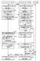
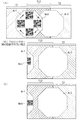
図4は、投写システム1で実行される接続情報の受け渡しの処理を示すシーケンス図である。図5及び図6は、接続情報の受け渡しの処理においてスクリーン40に投写される画像を説明する図である。
まず、プロジェクター10−1,10−2の撮像領域、及び画像を投写可能な投写可能領域を、図5(A)を参照して説明する。撮像領域T1は、プロジェクター10−1のカメラ部17が撮像する領域である。撮像領域T2は、プロジェクター10−2のカメラ部17が撮像する領域である。撮像領域T1と撮像領域T2とは、プロジェクター10−1,10−2が配列する方向と同じで、左右に並ぶ。撮像領域T1と撮像領域T2とは、撮像領域T12にて互いの一部の領域が重なり合っている。投写可能領域Ar1は、プロジェクター10−1が画像を投写可能な領域で、その全体が撮像領域T1に含まれている。また、投写可能領域Ar1は、その一部が撮像領域T2に含まれている。投写可能領域Ar2は、プロジェクター10−2が画像を投写可能な領域で、その全体が撮像領域T2に含まれている。また、投写可能領域Ar2は、その一部が撮像領域T1に含まれている。投写可能領域Ar1,Ar2は、レンズシフト機構により投写方向を変化させる制御によって画像の投写が可能な領域であり、この制御が行われない場合に比べて大きな領域となる。なお、図5(A)等に図示した投写可能領域Ar1,Ar2の形状は八角形になっているが、これは本実施形態で採用したレンズシフト機構の制限に基づくものであり、例えば四角形であってもかまわない。
Next, the operation of this embodiment will be described.
FIG. 4 is a sequence diagram showing a process of passing the connection information executed by the
First, the image pickup regions of the projectors 10-1 and 10-2 and the projectable region capable of projecting an image will be described with reference to FIG. The imaging region T1 is a region where the
続いて、図4のシーケンス図について説明する。
プロジェクター10−1は、まず、予め記憶した接続情報を用いてAP20に接続する(ステップS1)。次に、プロジェクター10−1は、マスターモードでの動作を開始する(ステップS2)。プロジェクター10−2は、スレーブモードでの動作を開始する(ステップS3)。スレーブモードで動作を開始したプロジェクター10−2は、撮像領域T2の撮像を開始する(ステップS4)。
なお、マスターモード又はスレーブモードによる動作の開始は、例えばユーザーにより所定の操作が行われたことが契機となるが、これ以外の契機であってもよい。
Next, the sequence diagram of FIG. 4 will be described.
The projector 10-1 first connects to the
Note that the start of the operation in the master mode or the slave mode is triggered by, for example, the user performing a predetermined operation, but may be triggered by other triggers.
マスターモードで動作を開始したプロジェクター10−1は、投写方向を複数の方向に変化させてPJ探索マークを投写する(ステップS5)。プロジェクター10−1は、上下方向及び左右方向の4方向に投写レンズ部163を移動させて、図5(B)に示すようにPJ探索マークIM1を4つの位置に投写する。PJ探索マークIM1は、矩形の画像領域の四隅に第1の識別画像Mr1を配置した画像である。第1の識別画像Mr1は、ここでは十字型の画像であるが、予め決められたパターンの画像であればよい。第1の識別画像Mr1は、少なくとも1回は、撮像領域T2に全体が投写されるものとする。ここでは、プロジェクター10−1は、図5(B)の矢印で示すように、PJ探索マークIM1を時計回りに順番に表示させるが、この順番については特に問わない。
プロジェクター10−1は、図5(B)で説明した方法でPJ探索マークIM1を投写すると、その投写を終了し、カメラ部17により撮像領域T1の撮像を開始する(ステップS6)。
The projector 10-1 that has started the operation in the master mode changes the projection direction to a plurality of directions and projects the PJ search mark (step S5). The projector 10-1 moves the
When the projector 10-1 projects the PJ search mark IM1 by the method described with reference to FIG. 5B, the projection is terminated and the
ステップS4で撮像を開始したプロジェクター10−2は、カメラ部17の撮像画像から、第1の識別画像Mr1を検出する処理を行う。図5(B)に示すように、投写可能領域Ar1内の右方向の領域にPJ探索マークIM1が投写された場合、プロジェクター10−2は、撮像領域T2に投写された第1の識別画像Mr1を検出する(ステップS7)。次に、プロジェクター10−2は、第1の識別画像Mr1を検出した位置に基づいて、プロジェクター10−1の方向を特定する(ステップS8)。図5(B)に示すように、プロジェクター10−2は、撮像領域T2内の左方向の領域で第1の識別画像Mr1を検出するため、プロジェクター10−1が存在する方向を左方向と特定する。
The projector 10-2, which has started image capturing in step S4, performs a process of detecting the first identification image Mr1 from the image captured by the
次に、プロジェクター10−2は、図5(C)に示すように、投写方向をステップS8で特定したプロジェクター10−1の方向として、応答マークIM2を投写する(ステップS9)。応答マークIM2は、矩形の画像領域の四隅に第2の識別画像Mr2を配置した画像である。第2の識別画像Mr2は、ここでは円形の画像であるが、予め決められたパターンの画像であればよい。第2の識別画像Mr2の少なくとも一つは、撮像領域T1で全体が表示されるものとする。 Next, as shown in FIG. 5C, the projector 10-2 projects the response mark IM2 with the projection direction as the direction of the projector 10-1 specified in step S8 (step S9). The response mark IM2 is an image in which the second identification image Mr2 is arranged at the four corners of the rectangular image area. Although the second identification image Mr2 is a circular image here, it may be an image having a predetermined pattern. At least one of the second identification images Mr2 is entirely displayed in the imaging area T1.
ステップS6で撮像を開始したプロジェクター10−1は、カメラ部17の撮像画像から、第2の識別画像Mr2を検出する処理を行う。図5(C)に示すように、投写可能領域Ar2内の左方向の領域に応答マークIM2が投写されるので、プロジェクター10−1は、撮像領域T1に投写された第2の識別画像Mr2を検出する(ステップS10)。次に、プロジェクター10−1は、第2の識別画像Mr2を検出した位置に基づいて、プロジェクター10−2の方向を特定する(ステップS11)。図5(C)に示すように、プロジェクター10−1は、撮像領域T1内の右方向の領域で第2の識別画像Mr2を検出する。よって、プロジェクター10−1は、プロジェクター10−2が存在する方向を右方向と特定する。
The projector 10-1, which has started image capturing in step S6, performs a process of detecting the second identification image Mr2 from the image captured by the
次に、プロジェクター10−1は、図6(A)に示すように、投写方向をステップS11で特定したプロジェクター10−2の方向として、コード画像Mr3を投写する(ステップS12)。コード画像Mr3は、本発明の第3の識別画像に相当する。コード画像Mr3は、ここでは、接続情報を符号化したQRコードである。コード画像Mr3は、その全体が撮像領域T2に投写される。
なお、コード画像Mr3は、QRコード以外のマトリクス型2次元コードやバーコード、2次元コードを時系列に変化させる3次元コードが使用されてもよい。
Next, as shown in FIG. 6A, the projector 10-1 projects the code image Mr3 with the projection direction as the direction of the projector 10-2 specified in step S11 (step S12). The code image Mr3 corresponds to the third identification image of the present invention. Here, the code image Mr3 is a QR code that encodes the connection information. The entire code image Mr3 is projected on the imaging region T2.
The code image Mr3 may be a matrix type two-dimensional code other than the QR code, a barcode, or a three-dimensional code that changes the two-dimensional code in time series.
プロジェクター10−2は、カメラ部17の撮像画像から、撮像領域T2内の左方向の領域に投写されたコード画像Mr3を検出する(ステップS13)。次に、プロジェクター10−2は、検出したコード画像Mr3に基づいて接続情報を取得する(ステップS14)。プロジェクター10−2は、公知のアルゴリズムで、コード画像Mr3から接続情報を復号することができる。次に、プロジェクター10−2は、取得した接続情報を記憶部18に記憶し、この接続情報を用いAP20に接続し、AP20を介してネットワークNWに接続する(ステップS15)。
The projector 10-2 detects the code image Mr3 projected in the leftward area in the imaging area T2 from the captured image of the camera unit 17 (step S13). Next, the projector 10-2 acquires connection information based on the detected code image Mr3 (step S14). The projector 10-2 can decode the connection information from the code image Mr3 with a known algorithm. Next, the projector 10-2 stores the acquired connection information in the
プロジェクター10−2は、AP20を介してネットワークNWに接続すると、接続完了を示す接続通知を、AP20及びネットワークNWを介してプロジェクター10−1へ送信する(ステップS16,S17)。プロジェクター10−1は、この接続通知を受信すると、マスターモードでの動作を終了する(ステップS18)。
When the projector 10-2 is connected to the network NW via the
接続通知を送信したプロジェクター10−2は、スレーブモードであるプロジェクター10−3に接続情報を受け渡すために、マスターモードでの動作を開始する(ステップS19)。以後において、プロジェクター10−2がマスターモードで動作し、プロジェクター10−3がスレーブモードで動作する受け渡しの処理が行われる。この受け渡しの処理は、図4の説明から類推できるので、説明を省略する。 The projector 10-2 that has transmitted the connection notification starts the operation in the master mode in order to transfer the connection information to the projector 10-3 in the slave mode (step S19). After that, the transfer process is performed in which the projector 10-2 operates in the master mode and the projector 10-3 operates in the slave mode. Since this transfer process can be inferred from the description of FIG. 4, description thereof will be omitted.
ステップS10の処理で、撮像を開始してから所定時間が経過しても第2の識別画像Mr2を検出しなかった場合は、プロジェクター10−1はタイムアウトとして、マスターモードでの動作を終了する。また、ステップS7の処理で、撮像を開始してから所定時間が経過しても第1の識別画像Mr1を検出しなかった場合は、プロジェクター10−2はタイムアウトとして、スレーブモードでの動作を終了する。
In the process of
ステップS16,S17の処理に代えて、プロジェクター10−2は、接続情報を取得すると、接続完了を示す接続完了マークをスクリーン40に投写してもよい。図6(B)に示すように、プロジェクター10−2は、投写方向をステップS8で特定した方向として、接続完了マークIM4を投写する。接続完了マークIM4は、矩形の画像領域の四隅に識別画像Mr4を配置した画像である。識別画像Mr4は、ここでは「OK」という文字列の画像であるが、予め決められたパターンの画像であればよい。プロジェクター10−1は、接続完了マークIM4を検出すると、マスターモードでの動作を終了する。プロジェクター10−2は、プロジェクター10−1とネットワークNWを介して接続されたこと、又は接続完了マークIM4を投写してから所定の時間が経過したことを条件としてスレーブモードでの動作を終了し、マスターモードでの動作を開始する。
投写システム1に含まれるプロジェクター10の台数が4台以上の場合も、同様の方法で、接続情報の受け渡しが可能である。
In place of the processing of steps S16 and S17, the projector 10-2 may project a connection completion mark indicating the completion of connection on the
Even when the number of
以上説明した第1実施形態の投写システム1によれば、マスターモードで動作するプロジェクター10は、投写方向を変えながら複数の方向に第1の識別画像Mr1を投写し、その後、スレーブモードで動作するプロジェクター10が投写した第2の識別画像Mr2を検出した場合は、その検出位置に応じて当該プロジェクター10の方向を特定する。そして、マスターモードで動作するプロジェクター10は、特定した方向を投写方向として、接続情報を示すコード画像Mr3を投写する。この投写方向を変化させる仕組みにより、投写可能領域が拡大するため、仮に複数のプロジェクター10間の距離が或る程度離れていても、接続情報の受け渡しが可能である。よって、接続情報の受け渡しの処理においては、複数のプロジェクター10の位置関係の影響を受け難い。また、スレーブモードで動作するプロジェクター10に対して、ユーザーは接続情報を手入力しなくてよいので、ユーザーの操作の負担も軽減される。
According to the
更に、スレーブモードで動作するプロジェクター10は、接続情報を取得した後はマスターモードで動作する。よって、図1に示すプロジェクター10−1、及びプロジェクター10−3のように、互いの距離が大きいプロジェクターが存在しても、接続情報の受け渡しが可能となる。受け渡した接続情報を活用することにより、プロジェクター10−1,10−2,10−3は、ネットワークNWを介して相互に接続することができ、タイリング投写をするために必要な情報交換を行う。また、プロジェクター10−1,10−2,10−3のそれぞれは、画像供給装置からネットワークNWとAP20を経由してタイリング投写を行うための画像を取得する。
Furthermore, the
[第2実施形態]
次に、本発明の第2実施形態を説明する。
本実施形態の投写システム1では、マスターで動作するプロジェクター10が、第1の識別画像Mr1に代えて、コード画像Mr3を投写する。また、本実施形態の投写システム1の全体構成及びハードウェア構成は、上述した第1実施形態と同じでよいから、これらの説明を省略する。
[Second Embodiment]
Next, a second embodiment of the present invention will be described.
In the
プロジェクター10−1の第1の投写制御手段103は、投写手段104の投写方向を複数の方向に変化させて接続情報を示す第1の識別画像を投写する手段である。第1の識別画像は、ここでは、記憶手段102に記憶された接続情報を示す画像である。
プロジェクター10−2の第2の検出手段112は、撮像手段111が撮像した画像から、撮像手段111の撮像領域に投写された第1の識別画像を検出する。
取得手段116は、検出された第1の識別画像に基づいて接続情報を取得する。
第3の投写制御手段113は、取得手段116により接続情報が取得されなかった場合、第1の識別画像が検出された位置に応じた方向に、第2の識別画像を投写する制御を行う。
The first
The
The
When the connection information is not acquired by the
プロジェクター10−1の第2の投写制御手段107は、投写手段104の投写方向を第1の識別画像が検出された位置に応じた方向として、記憶手段102に記憶された接続情報を示す第3の識別画像を投写する制御を行う。第3の識別画像は、記憶手段102に記憶された接続情報を示す第1の識別画像と異なる画像で、具体的には、第1の識別画像を縮小した画像を示す。
取得手段116は、検出された第3の識別画像に基づいて接続情報を取得する。
なお、プロジェクター10−1、及びプロジェクター10−2のその余の機能は上述した第1実施形態と同じでよい。また、プロジェクター10−3も、マスターモード及びスレーブモードで動作する。
The second
The
The remaining functions of the projector 10-1 and the projector 10-2 may be the same as those in the above-described first embodiment. The projector 10-3 also operates in the master mode and the slave mode.
次に、本実施形態の動作を説明する。
図7は、投写システム1で実行される接続情報の受け渡しの処理を示すシーケンス図である。図8は、接続情報の受け渡しの処理においてスクリーン40に投写される画像を説明する図である。
プロジェクター10−1は、AP20を介してネットワークNWに接続した後(ステップS1)、マスターモードでの動作を開始すると(ステップS2)、図8(A)に示すように、投写方向を複数の方向に変化させてコード画像Mr3を投写する(ステップS21)。コード画像Mr3は、本発明の第1の識別画像に相当する。ステップS21の制御は、投写する画像がコード画像Mr3に変わった点を除いて、ステップS5の処理と同じでよい。プロジェクター10−1は、コード画像Mr3を順番に投写すると、その投写を終了し、カメラ部17により撮像領域T1の撮像を開始する(ステップS22)。
Next, the operation of this embodiment will be described.
FIG. 7 is a sequence diagram showing a process of passing connection information, which is executed in the
When the projector 10-1 starts operation in the master mode (step S2) after connecting to the network NW via the AP 20 (step S1), as shown in FIG. And the code image Mr3 is projected (step S21). The code image Mr3 corresponds to the first identification image of the present invention. The control in step S21 may be the same as the processing in step S5, except that the image to be projected is changed to the code image Mr3. After projecting the code images Mr3 in order, the projector 10-1 ends the projection and starts the imaging of the imaging region T1 by the camera unit 17 (step S22).
プロジェクター10−2は、カメラ部17の撮像画像からコード画像Mr3を検出する処理を行う。ここでは、図8(A)に示すように、投写可能領域Ar1内の右方向の領域にコード画像Mr3が投写された場合に、プロジェクター10−2は、カメラ部17の撮像画像からコード画像Mr3を検出する(ステップS23)。次に、プロジェクター10−2は、コード画像Mr3に基づいて接続情報の取得を試みる(ステップS24)。そして、プロジェクター10−2は、コード画像Mr3を検出した位置に基づいてプロジェクター10−1の方向を特定する(ステップS25)。その後、プロジェクター10−2は、接続情報を取得したかどうかを判定する(ステップS26)。図8(A)に示す投写の場合、撮像領域T2にコード画像Mr3の全体が投写されている。この場合、プロジェクター10−2は、コード画像Mr3に基づいて接続情報を取得する。そして、プロジェクター10−2は、ステップS26で「YES」と判定し、ステップS15の処理に進める。この後、ステップS15,S16の各処理が行われるが、上述した第1実施形態と同じである。ステップS17において、プロジェクター10−2は、AP20を介してネットワークNWに接続すると、接続完了を示す接続通知と、ステップS25で特定したプロジェクター10−1の方向とを、AP20及びネットワークNWを介してプロジェクター10−1へ送信する。その後のステップS18,S19の各処理は上述した第1実施形態と同じである。
The projector 10-2 performs a process of detecting the code image Mr3 from the image captured by the
プロジェクター10−1とプロジェクター10−2との間の距離が大きい場合、撮像領域T2にコード画像Mr3の全体が投写されない場合がある。図8(B)の例では、プロジェクター10−2は、コード画像Mr3の右半分を撮像し、左半分を撮像できない。この場合、プロジェクター10−2は、例えばコード画像Mr3のシンボルを認識することにより、ステップS25にてコード画像Mr3の存在とプロジェクター10−1の方向を検出することはできるが、接続情報を取得することはできない。そこで、プロジェクター10−2は、ステップS26で「NO」と判定する。そして、プロジェクター10−2は、投写方向をステップS25で特定したプロジェクター10−1の方向として、応答マークIM2を投写する(ステップS9)。投写される画像は、図5(C)と同じでよい。 When the distance between the projector 10-1 and the projector 10-2 is large, the entire code image Mr3 may not be projected in the imaging region T2. In the example of FIG. 8B, the projector 10-2 images the right half of the code image Mr3 and cannot image the left half. In this case, the projector 10-2 can detect the presence of the code image Mr3 and the direction of the projector 10-1 in step S25 by recognizing the symbol of the code image Mr3, but acquires the connection information. It is not possible. Therefore, the projector 10-2 determines “NO” in step S26. Then, the projector 10-2 projects the response mark IM2 with the projection direction as the direction of the projector 10-1 specified in step S25 (step S9). The projected image may be the same as that in FIG.
プロジェクター10−1は、撮像領域T1に投写された応答マークIM2の第2の識別画像Mr2を検出する(ステップS10)。次に、プロジェクター10−1は、第2の識別画像Mr2を検出した位置に基づいて、プロジェクター10−2の方向を特定する(ステップS11)。次に、プロジェクター10−1は、投写方向をステップS11で特定したプロジェクター10−2の方向として、コード画像を縮小して投写する(ステップS27)。図8(C)に示すように、プロジェクター10−1は、コード画像Mr3を縮小した画像を示すコード画像Mr5を投写する。縮小する理由は、接続情報を示すコード画像の全体が撮像領域T2に投写されるようにするためである。プロジェクター10−2は、ステップS13でコード画像Mr5を検出すると、コード画像Mr5から接続情報を取得する(ステップS14)。この後、ステップS15〜S19の各処理が行われるが、上述した第1実施形態と同じであるが、上述したように、特定したプロジェクター10−1の方向をステップS17にて伝えることにしてもよい。
なお、ステップS26でプロジェクター10−2が接続情報を取得したと判定した場合は、ステップS17にてプロジェクター10−2からプロジェクター10−1へ接続通知と特定した方向が送信されるので、その場合は、ステップS22の撮像処理を終了し、ステップS18の処理を実行する。
The projector 10-1 detects the second identification image Mr2 of the response mark IM2 projected on the imaging region T1 (step S10). Next, the projector 10-1 specifies the direction of the projector 10-2 based on the position where the second identification image Mr2 is detected (step S11). Next, the projector 10-1 reduces the code image and projects the code image with the projection direction as the direction of the projector 10-2 identified in step S11 (step S27). As shown in FIG. 8C, the projector 10-1 projects a code image Mr5 showing a reduced image of the code image Mr3. The reason for reducing the size is that the entire code image indicating the connection information is projected on the imaging region T2. Upon detecting the code image Mr5 in step S13, the projector 10-2 acquires connection information from the code image Mr5 (step S14). After that, each processing of steps S15 to S19 is performed, which is the same as the above-described first embodiment, but as described above, the specified direction of the projector 10-1 is also transmitted in step S17. Good.
If it is determined in step S26 that the projector 10-2 has acquired the connection information, the direction specified as the connection notification is transmitted from the projector 10-2 to the projector 10-1 in step S17. In that case, Then, the imaging process of step S22 is ended, and the process of step S18 is executed.
なお、ステップS14でも接続情報が取得しなかった場合は、再びステップS9〜S27の処理が実行されて、コード画像が更に縮小されるようにしてもよい。ただし、コード画像が小さすぎると接続情報の復号が不可能になるので、プロジェクター10−1は接続情報の受け渡しが不可能である場合は、例えばスクリーン40への画像の投写によってユーザーに報知してもよい。
If the connection information is not acquired in step S14, the processing in steps S9 to S27 may be executed again to further reduce the code image. However, if the code image is too small, the connection information cannot be decoded. Therefore, if the projector 10-1 cannot receive the connection information, the projector 10-1 notifies the user by projecting the image on the
以上説明した第2実施形態の投写システム1によれば、マスターモードで動作するプロジェクター10は、投写方向を変えながらコード画像Mr3を投写する。よって、スレーブモードで動作するプロジェクター10が、このコード画像から接続情報を取得した場合は、上述した第1実施形態の場合よりも、ネットワークNWに接続するまでの時間が短くなる。また、この接続情報が取得されなかった場合でも、マスターモードで動作するプロジェクター10は、コード画像Mr3を縮小したコード画像Mr5を、スレーブモードで動作するプロジェクター10の方向に投写する。よって、プロジェクター10間の距離が或る程度離れていても、接続情報の受け渡しが可能となる。これ以外にも、本実施形態の投写システム1によれば、上述した第1実施形態と同等の効果を奏する。
According to the
[変形例]
本発明は、上述した実施形態と異なる形態で実施することが可能である。また、以下に示す変形例は、各々を適宜に組み合わせてもよい。
上述した各実施形態では、プロジェクター10は、レンズシフト機構を用いて投写方向を変化させていたが、この変化のための具体的な仕組みは特に問わない。例えば、プロジェクター10は、例えば、反射部材としてのミラーや、レンズ等の光学部材を組み合わせた機構により、投写方向を変化させてもよい。
[Modification]
The present invention can be implemented in a mode different from the above-described embodiment. Moreover, each of the modifications described below may be appropriately combined.
In each of the above-described embodiments, the
マスターモードで動作するプロジェクター10は、上下方向及び左右方向の4方向を投写方向として、識別画像を投写する構成でなくてもよい。例えば、プロジェクター10が左右又は上下方向にしか隣り合わない場合は、2方向にのみ投写すればよい。また、プロジェクター10は、4方向よりも多い方向を投写方向として識別画像を投写してもよい。
The
マスターで動作するプロジェクター10は、アクセスポイントの機能を備えてもよい。この場合、スレーブで動作するプロジェクター10は、マスターで動作するプロジェクター10に接続情報を用いて接続することとなる。
プロジェクター10は、反射型の液晶パネルや、デジタルマイクロミラーデバイス(DMD)等を採用したプロジェクターであってもよい。
上述した実施形態の投写システム1の構成又は動作の一部は適宜省略されてもよい。
The
The
Part of the configuration or operation of the
上述した実施形態において、マスターで動作するプロジェクター10とスレーブで動作するプロジェクター10をネットワーク接続するための接続情報を受け渡す方法を記述した。しかしながら、本発明において、マスターで動作するプロジェクター10とスレーブで動作するプロジェクター10の間で受け渡す情報は接続情報だけに限られない。お互いの駆動条件(投写画像の輝度や色合い、投写サイズ等)を受け渡すことも可能である。お互いの駆動条件を受け渡すことにより、タイリング投写された画像をなめらかにつなげることができる。
In the above-described embodiment, the method of passing the connection information for network-connecting the
上述した実施形態において、プロジェクター10が実現する各機能は、複数のプログラムの組み合わせによって実現され、又は、複数のハードウェア資源の連係によって実現され得る。また、プロジェクター10の機能が、プログラムを用いて実現される場合、このプログラムは、磁気記録媒体(磁気テープ、磁気ディスク(HDD(Hard Disk Drive)、FD(Flexible Disk))等)、光記録媒体(光ディスク等)、光磁気記録媒体、半導体メモリー等のコンピューター読み取り可能な記録媒体に記憶した状態で提供されてもよいし、ネットワークを介して配信されてもよい。また、本発明は、プロジェクターの制御方法として把握することも可能である。
In the above-described embodiment, each function realized by the
1…投写システム、10−1,10−2,10−3…プロジェクター、101,118…接続手段、102,117…記憶手段、103…第1の投写制御手段、104,114…投写手段、105,111…撮像手段、106…第1の検出手段、107…第2の投写制御手段、112…第2の検出手段、113…第3の投写制御手段、115…第3の検出手段、116…取得手段、11…CPU、12…ROM、13…RAM、14…操作部、15…画像処理部、16…投写部、161…光源、162…液晶パネル、163…投写レンズ部、164…光源制御部、165…パネル駆動部、166…レンズ駆動部、17…カメラ部、18…記憶部、19…通信部、20…AP、30…指示体、40…スクリーン
DESCRIPTION OF
Claims (8)
前記ネットワークへの接続に用いられる接続情報を記憶する記憶手段と、
投写面に画像を投写する投写手段と、
前記投写手段の投写方向を複数の方向に変化させて第1の識別画像を投写する第1の投写制御手段と、
前記投写面を撮像する撮像手段と、
前記第1の識別画像を撮像した他のプロジェクターにより前記撮像手段の撮像領域に投写された第2の識別画像を、前記撮像手段が撮像した画像から検出する第1の検出手段と、
前記投写方向を前記第2の識別画像が検出された位置に応じた方向として、前記記憶手段に記憶された接続情報を示す画像であって、前記他のプロジェクターにより撮像されることで前記接続情報を前記他のプロジェクターが取得し、前記接続情報で前記他のプロジェクターが前記ネットワークに接続する第3の識別画像を投写する第2の投写制御手段と
を備えるプロジェクター。 Connection means to connect to the network,
Storage means for storing connection information used for connection to the network,
Projection means for projecting an image on the projection surface,
First projection control means for projecting a first identification image by changing the projection direction of the projection means to a plurality of directions;
Imaging means for imaging the projection surface;
First detection means for detecting, from the image captured by the image capturing means, a second identification image projected in the image capturing area of the image capturing means by another projector that has captured the first identification image,
It is an image showing connection information stored in the storage means with the projection direction as a direction corresponding to the position where the second identification image is detected, and the connection information is obtained by being imaged by the other projector. And a second projection control means for projecting a third identification image for the other projector to connect to the network with the connection information.
前記他のプロジェクターが投写した前記第4の識別画像を検出した位置に基づいて、第5の識別画像を投写する第3の投写制御手段と、
前記他のプロジェクターにより前記撮像領域に投写された第6の識別画像を、前記撮像手段が撮像した画像から検出する第3の検出手段と、
検出された前記第6の識別画像に基づいて前記接続情報を取得する取得手段と
を備え、
前記接続手段は、
取得された前記接続情報を用いて、前記ネットワークに接続する
ことを特徴とする請求項1に記載のプロジェクター。 When acquiring connection information stored in a storage unit of the other projector from the other projector, a fourth identification image projected by the image capturing unit on the image capturing area by the other projector is acquired. Second detection means for detecting an image,
Third projection control means for projecting a fifth identification image based on a position where the fourth identification image projected by the other projector is detected;
Third detection means for detecting a sixth identification image projected on the image pickup area by the other projector from the image picked up by the image pickup means,
An acquisition unit that acquires the connection information based on the detected sixth identification image,
The connection means is
The projector according to claim 1, wherein the projector is connected to the network using the acquired connection information.
前記ネットワークへの接続に用いられる接続情報を記憶する記憶手段と、
投写面に画像を投写する投写手段と、
前記投写手段の投写方向を複数の方向に変化させて、前記記憶手段に記憶された接続情報を示す第1の識別画像を投写する第1の投写制御手段と、
前記投写面を撮像する撮像手段と、
前記第1の識別画像を撮像した他のプロジェクターが、撮像した前記第1の識別画像から前記接続情報を取得できなかった場合に、前記他のプロジェクターにより前記撮像手段の撮像領域に投写された第2の識別画像を、前記撮像手段が撮像した画像から検出する第1の検出手段と、
前記投写方向を前記第2の識別画像が検出された位置に応じた方向として、前記記憶手段に記憶された接続情報を示す前記第1の識別画像を縮小した画像であって、前記他のプロジェクターにより撮像されることで前記接続情報を前記他のプロジェクターが取得し、前記接続情報で前記他のプロジェクターが前記ネットワークに接続する第3の識別画像を投写する第2の投写制御手段と
を備えるプロジェクター。 Connection means to connect to the network,
Storage means for storing connection information used for connection to the network,
Projection means for projecting an image on the projection surface,
First projection control means for changing the projection direction of the projection means to a plurality of directions and projecting a first identification image indicating the connection information stored in the storage means;
Imaging means for imaging the projection surface;
When the other projector that has captured the first identification image cannot acquire the connection information from the captured first identification image, the other projector that is projected on the image capturing area of the image capturing unit by the other projector. First detecting means for detecting the second identification image from the image captured by the image capturing means;
An image obtained by reducing the first identification image indicating the connection information stored in the storage unit, with the projection direction being a direction corresponding to the position where the second identification image is detected, and the other projector. And a second projection control means for projecting a third identification image for the other projector to connect to the network with the connection information. .
検出された前記第4の識別画像に基づいて前記接続情報を取得する取得手段と、
前記接続情報が取得されなかった場合、前記他のプロジェクターが投写した前記第4の識別画像を検出した位置に基づいて、第5の識別画像を投写する第3の投写制御手段と、
前記他のプロジェクターにより前記撮像領域に投写された前記第4の識別画像を縮小した第6の識別画像を、前記撮像手段が撮像した画像から検出する第3の検出手段と
を備え、
前記取得手段は、
検出された前記第6の識別画像に基づいて前記接続情報を取得し、
前記接続手段は、
取得された前記接続情報を用いて、前記ネットワークに接続する
ことを特徴とする請求項3に記載のプロジェクター。 When acquiring the connection information stored in the storage unit of the other projector from the other projector, the other projector projected from the image captured by the image capturing unit onto the image capturing area by the other projector. Second detection means for detecting a fourth identification image indicating the connection information stored in the storage means of
Acquisition means for acquiring the connection information based on the detected fourth identification image;
Third projection control means for projecting a fifth identification image based on the position where the fourth identification image projected by the other projector is detected when the connection information is not acquired;
Third detection means for detecting a sixth identification image obtained by reducing the fourth identification image projected on the imaging area by the other projector from the image captured by the imaging means,
The acquisition means is
Acquiring the connection information based on the detected sixth identification image,
The connection means is
The projector according to claim 3, wherein the projector is connected to the network using the acquired connection information.
前記第1の投写制御手段、及び前記第2の投写制御手段は、
前記駆動手段を制御して、前記第1の識別画像及び前記第3の識別画像を投写する位置を変化させる
ことを特徴とする請求項1から請求項4のいずれか1項に記載のプロジェクター。 The projection unit includes a projection lens that emits image light representing an image toward the projection surface, and a drive unit that moves the projection lens.
The first projection control means and the second projection control means
The projector according to any one of claims 1 to 4, wherein the driving unit is controlled to change a position at which the first identification image and the third identification image are projected.
ことを特徴とする請求項1から請求項5のいずれか1項に記載のプロジェクター。 The image pickup unit is an image pickup unit for correction processing for picking up an image on the projection plane and correcting the image, or for position detection for detecting a position of a pointer indicating a position on the projection plane. The projector according to any one of claims 1 to 5, characterized in that:
前記ネットワークへの接続に用いられる接続情報を記憶する記憶手段と、
投写面に画像を投写する投写手段と
を備えるプロジェクターの制御方法であって、
前記投写手段の投写方向を複数の方向に変化させて第1の識別画像を投写するステップと、
前記投写面を撮像するステップと、
前記第1の識別画像を撮像した他のプロジェクターにより前記撮像するステップの撮像領域に投写された第2の識別画像を、撮像した画像から検出するステップと、
前記投写方向を前記第2の識別画像が検出された位置に応じた方向として、前記記憶手段に記憶された接続情報を示す画像であって、前記他のプロジェクターにより撮像されることで前記接続情報を前記他のプロジェクターが取得し、前記接続情報で前記他のプロジェクターが前記ネットワークに接続する第3の識別画像を投写するステップと
を備えるプロジェクターの制御方法。 Connection means to connect to the network,
Storage means for storing connection information used for connection to the network,
A method for controlling a projector, comprising: a projection unit that projects an image on a projection surface,
Changing the projection direction of the projection means to a plurality of directions and projecting the first identification image;
Imaging the projection surface,
A step of detecting, from the imaged image, a second identification image projected in the imaging area of the step of imaging by another projector that has captured the first identification image;
It is an image showing the connection information stored in the storage means, wherein the projection direction is a direction corresponding to the position where the second identification image is detected, and the connection information is obtained by being imaged by the other projector. Is acquired by the other projector, and the third projector projects a third identification image connected to the network by the connection information using the connection information.
前記ネットワークへの接続に用いられる接続情報を記憶する記憶手段と、
投写面に画像を投写する投写手段と
を備えるプロジェクターの制御方法であって、
前記投写手段の投写方向を複数の方向に変化させて、前記記憶手段に記憶された接続情報を示す第1の識別画像を投写するステップと、
前記投写面を撮像するステップと、
前記第1の識別画像を撮像した他のプロジェクターが、撮像した前記第1の識別画像から前記接続情報を取得できなかった場合に、前記他のプロジェクターにより前記撮像するステップの撮像領域に投写された第2の識別画像を、撮像した画像から検出するステップと、
前記投写方向を前記第2の識別画像が検出された位置に応じた方向として、前記記憶手段に記憶された接続情報を示す前記第1の識別画像を縮小した画像であって、前記他のプロジェクターにより撮像されることで前記接続情報を前記他のプロジェクターが取得し、前記接続情報で前記他のプロジェクターが前記ネットワークに接続する第3の識別画像を投写するステップと
を備えるプロジェクターの制御方法。 Connection means to connect to the network,
Storage means for storing connection information used for connection to the network,
A method for controlling a projector, comprising: a projection unit that projects an image on a projection surface,
Changing the projection direction of the projection means to a plurality of directions, and projecting a first identification image indicating the connection information stored in the storage means;
Imaging the projection surface,
When the other projector that has captured the first identification image cannot acquire the connection information from the captured first identification image, it is projected by the other projector in the imaging region of the step of capturing the image. Detecting the second identification image from the captured image,
An image obtained by reducing the first identification image indicating the connection information stored in the storage unit with the projection direction being a direction corresponding to the position where the second identification image is detected, and the other projector. The other projector acquires the connection information by being imaged by, and the other projector projects a third identification image to connect to the network with the connection information.
Priority Applications (4)
| Application Number | Priority Date | Filing Date | Title |
|---|---|---|---|
| JP2015061402A JP6701621B2 (en) | 2015-03-24 | 2015-03-24 | Projector and projector control method |
| PCT/JP2016/001178 WO2016152043A1 (en) | 2015-03-24 | 2016-03-03 | Projector and projector control method |
| US15/557,335 US10104346B2 (en) | 2015-03-24 | 2016-03-03 | Projector and control method for projector |
| CN201680013792.3A CN107534753B (en) | 2015-03-24 | 2016-03-03 | Projector and control method of projector |
Applications Claiming Priority (1)
| Application Number | Priority Date | Filing Date | Title |
|---|---|---|---|
| JP2015061402A JP6701621B2 (en) | 2015-03-24 | 2015-03-24 | Projector and projector control method |
Publications (3)
| Publication Number | Publication Date |
|---|---|
| JP2016181824A JP2016181824A (en) | 2016-10-13 |
| JP2016181824A5 JP2016181824A5 (en) | 2018-04-26 |
| JP6701621B2 true JP6701621B2 (en) | 2020-05-27 |
Family
ID=56977197
Family Applications (1)
| Application Number | Title | Priority Date | Filing Date |
|---|---|---|---|
| JP2015061402A Active JP6701621B2 (en) | 2015-03-24 | 2015-03-24 | Projector and projector control method |
Country Status (4)
| Country | Link |
|---|---|
| US (1) | US10104346B2 (en) |
| JP (1) | JP6701621B2 (en) |
| CN (1) | CN107534753B (en) |
| WO (1) | WO2016152043A1 (en) |
Families Citing this family (3)
| Publication number | Priority date | Publication date | Assignee | Title |
|---|---|---|---|---|
| CN107027014A (en) * | 2017-03-23 | 2017-08-08 | 广景视睿科技(深圳)有限公司 | A kind of intelligent optical projection system of trend and its method |
| CN109558062A (en) * | 2018-03-29 | 2019-04-02 | 广州小狗机器人技术有限公司 | A kind of determination method and apparatus of interactive placement |
| CN112040210B (en) * | 2020-09-11 | 2022-01-18 | 深圳市当智科技有限公司 | Wide screen projection system, method, apparatus and readable storage medium |
Family Cites Families (10)
| Publication number | Priority date | Publication date | Assignee | Title |
|---|---|---|---|---|
| US7348963B2 (en) * | 2002-05-28 | 2008-03-25 | Reactrix Systems, Inc. | Interactive video display system |
| JP4274217B2 (en) * | 2006-09-21 | 2009-06-03 | セイコーエプソン株式会社 | Image display device, image display system, and network connection method |
| JP4407841B2 (en) * | 2007-07-13 | 2010-02-03 | セイコーエプソン株式会社 | Display system and display device |
| JP5263474B2 (en) * | 2007-10-02 | 2013-08-14 | セイコーエプソン株式会社 | IDENTIFICATION SYSTEM, PROJECTOR, PROGRAM, AND IDENTIFICATION METHOD |
| JP2011070086A (en) * | 2009-09-28 | 2011-04-07 | Seiko Epson Corp | Projector, projection system, method of controlling the system |
| JP2011133669A (en) * | 2009-12-24 | 2011-07-07 | Sanyo Electric Co Ltd | Projection type video display device |
| US8902158B2 (en) * | 2011-10-21 | 2014-12-02 | Disney Enterprises, Inc. | Multi-user interaction with handheld projectors |
| CN103209311A (en) * | 2012-01-14 | 2013-07-17 | 复旦大学 | Multi-projection autocorrection display system based on camera |
| US20130229396A1 (en) * | 2012-03-05 | 2013-09-05 | Kenneth J. Huebner | Surface aware, object aware, and image aware handheld projector |
| JP2015169952A (en) * | 2014-03-04 | 2015-09-28 | セイコーエプソン株式会社 | Communication system, imaging apparatus, program, and communication method |
-
2015
- 2015-03-24 JP JP2015061402A patent/JP6701621B2/en active Active
-
2016
- 2016-03-03 US US15/557,335 patent/US10104346B2/en active Active
- 2016-03-03 WO PCT/JP2016/001178 patent/WO2016152043A1/en active Application Filing
- 2016-03-03 CN CN201680013792.3A patent/CN107534753B/en active Active
Also Published As
| Publication number | Publication date |
|---|---|
| CN107534753B (en) | 2020-06-16 |
| CN107534753A (en) | 2018-01-02 |
| JP2016181824A (en) | 2016-10-13 |
| WO2016152043A1 (en) | 2016-09-29 |
| US20180054601A1 (en) | 2018-02-22 |
| US10104346B2 (en) | 2018-10-16 |
Similar Documents
| Publication | Publication Date | Title |
|---|---|---|
| US10681320B2 (en) | Projection apparatus, method for controlling projection apparatus, and non-transitory storage medium | |
| JP6711271B2 (en) | Image processing apparatus and method | |
| KR101969244B1 (en) | Communication apparatus, method of controlling communication apparatus, computer-readable storage medium | |
| US10382731B2 (en) | Projector, multi-projection system, and method for controlling projector | |
| JP2020134895A (en) | Method for display and display system | |
| JP6701621B2 (en) | Projector and projector control method | |
| JP6601032B2 (en) | Display device, display system, display device control method, and electronic device control method | |
| JP6503681B2 (en) | Time multiplexing system, method and program of temporal pixel position data and interactive image projection for interactive projection | |
| JP2020092337A (en) | Method for controlling display unit, display unit, and display system | |
| US20160259609A1 (en) | Display apparatus, display system, and control method for display apparatus | |
| JP6582379B2 (en) | Information processing system | |
| JP2019117989A (en) | Projector, multi-projection system, and projector control method | |
| JP2019045549A (en) | Image projection system, terminal device, and control method for image projection system | |
| JP2020009152A (en) | Image display system, image display device, and control method of the image display system | |
| JP6464834B2 (en) | Display device and display method | |
| JP6986214B2 (en) | Display system and display device | |
| US11947759B2 (en) | Projection system sharing image between projection device and display device | |
| JP5630853B2 (en) | Projection type display device, adjustment processing device, receiver, display system, and display method | |
| WO2023127501A1 (en) | Control device, control method, and control program | |
| US20180348615A1 (en) | Display apparatus and method for controlling display apparatus | |
| US11800070B2 (en) | Control method for projector, projector, and image projection system | |
| US20230171384A1 (en) | Projection system and method of controlling projection system | |
| US20230199159A1 (en) | Projection system, and control method for projection system | |
| JP2020005049A (en) | Projection system, projector, control method for projection system, and control method for projector | |
| JP2023125177A (en) | Method for adjusting projection image, projection system, and control unit |
Legal Events
| Date | Code | Title | Description |
|---|---|---|---|
| A521 | Request for written amendment filed |
Free format text: JAPANESE INTERMEDIATE CODE: A523 Effective date: 20180316 |
|
| A621 | Written request for application examination |
Free format text: JAPANESE INTERMEDIATE CODE: A621 Effective date: 20180316 |
|
| A131 | Notification of reasons for refusal |
Free format text: JAPANESE INTERMEDIATE CODE: A131 Effective date: 20190604 |
|
| A521 | Request for written amendment filed |
Free format text: JAPANESE INTERMEDIATE CODE: A523 Effective date: 20190726 |
|
| A131 | Notification of reasons for refusal |
Free format text: JAPANESE INTERMEDIATE CODE: A131 Effective date: 20191001 |
|
| A521 | Request for written amendment filed |
Free format text: JAPANESE INTERMEDIATE CODE: A523 Effective date: 20191112 |
|
| TRDD | Decision of grant or rejection written | ||
| A01 | Written decision to grant a patent or to grant a registration (utility model) |
Free format text: JAPANESE INTERMEDIATE CODE: A01 Effective date: 20200407 |
|
| A61 | First payment of annual fees (during grant procedure) |
Free format text: JAPANESE INTERMEDIATE CODE: A61 Effective date: 20200420 |
|
| R150 | Certificate of patent or registration of utility model |
Ref document number: 6701621 Country of ref document: JP Free format text: JAPANESE INTERMEDIATE CODE: R150 |