JP6700366B2 - Wafer inspection system - Google Patents
Wafer inspection system Download PDFInfo
- Publication number
- JP6700366B2 JP6700366B2 JP2018208409A JP2018208409A JP6700366B2 JP 6700366 B2 JP6700366 B2 JP 6700366B2 JP 2018208409 A JP2018208409 A JP 2018208409A JP 2018208409 A JP2018208409 A JP 2018208409A JP 6700366 B2 JP6700366 B2 JP 6700366B2
- Authority
- JP
- Japan
- Prior art keywords
- test head
- maintenance
- cell
- case
- cart
- Prior art date
- Legal status (The legal status is an assumption and is not a legal conclusion. Google has not performed a legal analysis and makes no representation as to the accuracy of the status listed.)
- Active
Links
- 238000007689 inspection Methods 0.000 title claims description 31
- 238000012360 testing method Methods 0.000 claims description 115
- 239000004065 semiconductor Substances 0.000 claims description 10
- 238000012423 maintenance Methods 0.000 description 53
- 235000012431 wafers Nutrition 0.000 description 28
- 239000000523 sample Substances 0.000 description 18
- 230000007246 mechanism Effects 0.000 description 16
- 238000000034 method Methods 0.000 description 5
- 238000010586 diagram Methods 0.000 description 4
- 238000007789 sealing Methods 0.000 description 2
- 229910000679 solder Inorganic materials 0.000 description 2
- 238000012546 transfer Methods 0.000 description 2
- 239000000470 constituent Substances 0.000 description 1
- 238000012986 modification Methods 0.000 description 1
- 230000004048 modification Effects 0.000 description 1
Images


Landscapes
- Testing Or Measuring Of Semiconductors Or The Like (AREA)
Description
本発明は、複数のテストヘッドを有するウエハ検査装置に関する。 The present invention relates to a wafer inspection device having a plurality of test heads.
多数の半導体デバイスが形成された半導体ウエハ(以下、単に「ウエハ」という。)において各半導体デバイスの電気的特性検査を行うために、ウエハ検査装置としてのプローバが用いられている。プローバはウエハと対向するプローブカードを備え、プローブカードは複数の柱状接触端子であるコンタクトプローブを有する(例えば、特許文献1参照。)。このプローバでは、プローブカードの各コンタクトプローブが半導体デバイスにおける電極パッドや半田バンプに接続された半導体デバイスへ検査信号を流すことによって半導体デバイスの電気回路の導通状態等を検査する。 2. Description of the Related Art A prober as a wafer inspection apparatus is used to inspect an electric characteristic of each semiconductor device on a semiconductor wafer (hereinafter, simply referred to as “wafer”) on which a large number of semiconductor devices are formed. The prober has a probe card facing the wafer, and the probe card has contact probes that are a plurality of columnar contact terminals (see, for example, Patent Document 1). In this prober, each contact probe of a probe card sends an inspection signal to a semiconductor device connected to an electrode pad or a solder bump in the semiconductor device, thereby inspecting a conduction state of an electric circuit of the semiconductor device.
プローブカードの各コンタクトプローブへは検査回路であるメインボードを搭載したテストヘッドから検査信号が流されるが、近年、ウエハの検査効率を向上するために、それぞれにプローブカードが装着された複数のテストヘッドを備え、搬送ステージによって一のテストヘッドへウエハを搬送中に他のテストヘッドでウエハの半導体デバイスを検査可能なウエハ検査装置が開発されている。このウエハ検査装置では、フットプリント削減の観点から複数のテストヘッドを収容するセルが多段積みで配置される。 An inspection signal is sent to each contact probe of the probe card from a test head equipped with an inspection circuit main board, but in recent years, in order to improve the inspection efficiency of wafers, a plurality of tests with probe cards attached to each of them have been performed. A wafer inspection apparatus has been developed which includes a head and is capable of inspecting a semiconductor device of a wafer by another test head while the wafer is being transferred to one test head by a transfer stage. In this wafer inspection apparatus, cells for accommodating a plurality of test heads are arranged in multiple stages from the viewpoint of footprint reduction.
各テストヘッドのメインボードは一種の消耗品であるために定期的に交換する必要があるが、メインボードを交換するためにはテストヘッドをウエハ検査装置から整備用台車の上に引き出す必要がある。 The main board of each test head is a kind of consumable item and therefore needs to be replaced regularly, but in order to replace the main board, the test head needs to be pulled out from the wafer inspection device onto the maintenance cart. .
しかしながら、テストヘッドは重量が約70kgfであり、スライドレールで支持されるため、テストヘッドを引き出し方向以外に移動させるのは困難である。したがって、整備用台車の位置をテストヘッドの位置へ正確に合わせる必要があるが、整備用台車はリフト機構等を有し、重量が大きいために位置の微調整が困難であり、その結果、テストヘッドを引き出すのが困難であるという問題がある。 However, since the weight of the test head is about 70 kgf and it is supported by the slide rail, it is difficult to move the test head in a direction other than the pull-out direction. Therefore, it is necessary to accurately align the position of the maintenance trolley with the position of the test head, but the maintenance trolley has a lift mechanism, etc., and it is difficult to finely adjust the position due to its large weight. There is a problem that it is difficult to pull out the head.
本発明の目的は、テストヘッドを容易に引き出すことができるウエハ検査装置を提供することにある。 It is an object of the present invention to provide a wafer inspection device that can easily pull out a test head.
上記目的を達成するために、本発明のウエハ検査装置は、少なくとも上下に重ねられて配される複数の検査室を備え、前記複数の検査室のうちの少なくとも1つの検査室は、内部に半導体デバイスが形成されたウエハの検査の際に用いられる被整備テストヘッドを備え、さらに、前記被整備テストヘッドを引き出すために側壁に開設された開口部と、前記検査室内に配置されるスライドレールと、を有し、前記開口部を介して前記被整備テストヘッドが引き出されることを特徴とする。 To achieve the above object, a wafer inspection apparatus of the present invention includes at least a plurality of inspection chambers that are vertically stacked, and at least one inspection chamber of the plurality of inspection chambers has a semiconductor inside. A test head to be maintained, which is used when inspecting a wafer on which a device is formed, and an opening formed in a side wall for pulling out the test head to be maintained , and a slide rail arranged in the inspection chamber. , have a, the object maintenance test head through the opening is pulled out, characterized in Rukoto.
本発明によれば、被整備テストヘッドを容易に引き出すことができる。 According to the present invention, the maintenance test head can be easily pulled out.
以下、本発明の実施の形態について図面を参照しながら説明する。 Hereinafter, embodiments of the present invention will be described with reference to the drawings.
まず、本実施の形態に係るプローバについて説明する。 First, the prober according to the present embodiment will be described.
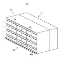
図1は、本実施の形態に係るプローバとしてのウエハ検査装置の構成を概略的に示す斜視図である。 FIG. 1 is a perspective view schematically showing the configuration of a wafer inspection device as a prober according to this embodiment.
図1において、ウエハ検査装置10は、複数の検査室(セル)11が多段、例えば、4段に配置されたセルタワー12と、該セルタワー12に隣接して配置され、搬送機構(図示しない)を内蔵してウエハの各セル11への搬出入を行うローダ13とを備える。セルタワー12及びローダ13はそれぞれ直方体状を呈し、高さは、例えば、2.4mである。
In FIG. 1, a
ウエハ検査装置10では、セルタワー12におけるローダ13との隣接面の反対側(以下、「外側」という。)には作業者が各セル11の整備作業を行うことが可能な空間が確保され、後述する整備用台車27が配置される。
In the
図2は、図1におけるセルタワーの各セルに内蔵される構成要素を説明するための図であり、図2(A)はテストヘッドの斜視図であり、図2(B)は各セルにおけるテスタヘッド、ポゴフレーム及びプローブカードの配置状態を示す正面図である。 2A and 2B are views for explaining constituent elements built in each cell of the cell tower in FIG. 1, FIG. 2A is a perspective view of a test head, and FIG. 2B is a tester in each cell. It is a front view showing the arrangement state of the head, the pogo frame, and the probe card.
図2(A)において、テストヘッド15は、直方体状の筐体からなる本体16と、本体16の長手方向の側面上部から側方へ突出するフランジ17とを有し、本体16は検査回路であるメインボード(図示しない)を収容する。
In FIG. 2A, the
また、図2(B)に示すように、各セル11は、内部において、テストヘッド15と、プローブカード18と、プローブカード18及びメインボードを電気的に接続するポゴピン(図示しない)を保持するポゴフレーム19とを有する。プローブカード18及びポゴフレーム19、並びにポゴフレーム19及びテストヘッド15の間にはシール部材20、21が配置され、該シール部材20、21に囲まれた空間が減圧されることにより、プローブカード18及びポゴフレーム19が真空吸着によってテストヘッド15へ装着される。
Further, as shown in FIG. 2B, each
プローブカード18は、円板状の本体24と、本体24の下面から図中下方へ向けて突出するように配置される多数の柱状接触端子である複数のコンタクトプローブ25とを有する。各コンタクトプローブ25は、プローブカード18へウエハ(図示しない)が当接した際、該ウエハに形成された各半導体デバイスの電極パッドや半田バンプ(いずれも図示しない)と接触する。
The
図1に戻り、各セル11の外側には整備用開口部26が開設され、該整備用開口部26を介してテストヘッド15が引き出される。作業者は引き出されたテストヘッド15から消耗したメインボードを取り外し、新しいメインボードを取り付ける。
Returning to FIG. 1, a
ところで、テストヘッド15の重量は約70kgfであり、作業者の力だけでは取り扱いが困難であるため、テストヘッド15は、セル11内において当該テストヘッド15の長手方向(以下、単に「長手方向」という。)に沿って配置されるスライドレール(図示しない)によってフランジ17を介して支持され、スライドレールの上面に設けられた複数のボール台座によって長手方向に引き出し可能に構成される。
By the way, since the weight of the
ウエハ検査装置10において、作業者が容易にメインボードの交換を行うためには引き出されたテストヘッド15を支持する支持機構が必要であり、これに対応して、本実施の形態では後述する整備用台車27が提供される。
In the
図3は、本実施の形態に係るプローバに用いられる整備用台車の構成を概略的に示す図であり、図3(A)は側面図であり、図3(B)は正面図である。 FIG. 3 is a diagram schematically showing a configuration of a maintenance cart used for the prober according to the present embodiment, FIG. 3(A) is a side view, and FIG. 3(B) is a front view.
図3(A)及び図3(B)において、整備用台車27は、複数のころ28(車輪)によって支持されて移動可能に構成される台車基部29と、該台車基部29から立設されたリフト機構30と、テストヘッド15を収容可能な筐体状のテストヘッドケース31(ケース)とを有する。
3(A) and 3(B), the
台車基部29には取っ手32が設けられ、作業者は取って32を押すか、若しくは引くことによって整備用台車27を移動させる。各ころ28は双輪からなり、向きを自在に変更可能に構成されるため、整備用台車27の移動に関する自由度を向上させる。
The
リフト機構30は、図中上方へ向けて台車基部29から延出する支柱33と、該支柱33に取り付けられ、支柱33の延出方向に沿って移動することによって図中上下方向に移動するリフタ34と、リフタ34を移動させるモータ(図示しない)とを有する。
The
なお、台車基部29の各ころ28はブレーキ(図示しない)を有し、該ブレーキはリフタ34が上下方向に関する最下点に位置する場合のみ解除される。
Each
図4は、図3(A)及び図3(B)におけるリフタ及びテストヘッドケースの構成を概略的に示す図であり。図4(A)は側面図であり、図4(B)は正面図である。なお、説明を簡単にするために、図4(A)及び図4(B)では、テストヘッド15が破線で示され、さらに、図4(B)は、後述するスライドレールカバー40を一点鎖線で示し、且つスライドレールカバー40を透けた状態で示す。
FIG. 4 is a diagram schematically showing the configurations of the lifter and the test head case shown in FIGS. 3(A) and 3(B). FIG. 4A is a side view and FIG. 4B is a front view. 4(A) and 4(B), the
図4(A)及び図4(B)に示すように、テストヘッドケース31は直方体状を呈するとともに、長手方向に関する両端が開放されて開口部を形成し、テストヘッド15をセル11から引き出す際、両端の開口部のいずれかがセル11の整備用開口部26に対向し、整備用開口部26を介して引き出されたテストヘッド15を内部に収容する。また、テストヘッドケース31の上面も開放されているため、作業者は収容されたテストヘッド15へテストヘッドケース31の上面からアクセス可能であり、該上面を介してメインボードを交換する。
As shown in FIGS. 4(A) and 4(B), the
テストヘッドケース31は水平位置調整ステージ35を介してリフタ34によって支持される。水平位置調整ステージ35は上下に重ねられた円板状部材である基部35a及び移動部35bからなり、基部35a及び移動部35bの間には多数のボールベアリング(図示しない)が敷き詰められ、移動部35bは基部35aに対して水平に移動することができる。基部35aはリフタ34に接続され、移動部35bはテストヘッドケース31に接続される。これにより、水平位置調整ステージ35はテストヘッドケース31をリフタ34に対して水平に移動させることができる。
The
また、水平位置調整ステージ35では、外部からエアを送り込むことにより、基部35aの一部及び移動部35bの一部を係合させる等して移動部35bを基部35aに対して固定することもできる。
Further, in the horizontal
移動部35bの移動は多数のボールベアリングによって実現されるため、移動部35bの移動には大きな力が必要なく、その結果、テストヘッドケース31は作業者によって容易に水平へ移動させることができる。なお、テストヘッドケース31の下面から下方に向けて板状のストッパ36が突出し、テストヘッドケース31の水平方向の移動量が所定量に達した場合、ストッパ36が水平位置調整ステージ35の基部35aに当接することにより、テストヘッドケース31の水平方向の移動量が規制される。
Since the movement of the moving
テストヘッドケース31の長手方向に関する両側面の上部には複数のボール台座からなるスライドレール37が配される。スライドレール37はテストヘッドケース31に収容されたテストヘッド15のフランジ17を支持し、テストヘッド15をテストヘッドケース31の長手方向にスライドさせる。
Slide rails 37 formed of a plurality of ball pedestals are arranged on upper portions of both side surfaces in the longitudinal direction of the
また、テストヘッドケース31の長手方向に関する両側面の上部における両端にはストッパ機構38(固定機構)が配される。ストッパ機構38は突出自在な突起状の接触子39を有し、該接触子39が突出してテストヘッド15のフランジ17に接触することにより、テストヘッド15の位置がテストヘッドケース31に対して固定される。なお、リフト機構30は、テストヘッド15がテストヘッドケース31に収容される際、接触子39がフランジ17に接触していない場合は、リフタ34が上下動不可能に構成される。
Further, stopper mechanisms 38 (fixing mechanisms) are arranged at both ends of the upper portions of both side surfaces in the longitudinal direction of the
テストヘッド15をテストヘッドケース31の長手方向にスライドさせる際、作業者の手、特に、指がフランジ17とスライドレール37の間に挟まれる危険性があるため、スライドレール37はスライドレールカバー40によって覆われる。
When the
整備用台車27では、リフト機構30が、テストヘッドケース31の位置を、当該テストヘッドケース31のスライドレール37が1段目のセル11に収容されたテストヘッド15のフランジ17と正対する高さ、同スライドレール37が2段目のセル11に収容されたテストヘッド15のフランジ17と正対する高さ、同スライドレール37が3段目のセル11に収容されたテストヘッド15のフランジ17と正対する高さ、及び同スライドレール37が4段目のセル11に収容されたテストヘッド15のフランジ17と正対する高さのそれぞれに固定可能である。
In the
図1に戻り、セルタワー12の外側下方にはガイドレール41が配される。ガイドレール41はセルタワー12の長手方向に沿い、断面が矩形の管状体であり、セルタワー12と反対側の側壁41aにスリット42が形成される。一方、図3(B)に示すように、整備用台車27は台車基部29に配されたガイド部43(ガイド機構)を有する。
Returning to FIG. 1, a
図5に示すように、ガイド部43は台車基部29から側方へ突出するブラケット43aと、該ブラケット43aの先端に設けられて水平に回転するローラ43bとを有し、ブラケット43aはガイドレール41のスリット42を介してガイドレール41の内部へ進入し、ローラ43bはガイドレール41の内部に収容される。すなわち、ガイド部43はガイドレール41と遊合するが、このとき、ローラ43b及び台車基部29の間にはガイドレール41の側壁41aが介在する。
As shown in FIG. 5, the
上述した整備用台車27はテストヘッド15の全体を引き出す際に用いられるが、テストヘッド15を整備する際、当該テストヘッド15の全体を引き出す必要がない場合がある。このような場合、ウエハ検査装置10では、整備用台車27ではなくテストヘッド15を部分的に載置する簡易整備用台車44を用いる。
Although the trolley|
図6は、簡易整備用台車の構成を概略的に示す側面図であり、図6(A)はセルタワーにおける1段目のセルのテストヘッドを整備する場合を示し、図6(B)はセルタワーにおける2段目のセルのテストヘッドを整備する場合を示す。 FIG. 6 is a side view schematically showing the configuration of the simple maintenance cart, FIG. 6(A) shows a case where the test head of the first-stage cell in the cell tower is to be serviced, and FIG. 6(B) is the cell tower. The case of servicing the test head of the second-stage cell in FIG.
図6(A)及び図6(B)において、簡易整備用台車44は底部に複数のころ45が配置されたメインフレーム46と、該メインフレーム46に対して上下に移動可能な整備台47とを有する。整備台47は複数のボール台座からなるスライドレール48を有し、スライドレール48は部分的に引き出されたテストヘッド15のフランジ17を支持する。整備台47は、スライドレール48が1段目のセル11に収容されたテストヘッド15のフランジ17と正対する第1の高さ、及びスライドレール48が2段目のセル11に収容されたテストヘッド15のフランジ17と正対する第2の高さのそれぞれに固定可能に構成される。
6(A) and 6(B), the
簡易整備用台車44は整備用台車27に比べて大幅に簡素化されて軽量であり、且つ、メインフレーム46の底部に配置された複数のころ45を有するため、作業者は簡易整備用台車44の位置を容易に調整することができ、もって、1段目や2段目のセル11に収容されたテストヘッド15のフランジ17と、整備台47のスライドレール48とを正確に正対させることができる。その結果、1段目や2段目のセル11から容易にテストヘッド15を部分的に引き出すことができる。
The
図7は、図3の整備用台車を用いるウエハ検査装置の整備方法を説明するための工程図である。 FIG. 7 is a process diagram for explaining a method of servicing a wafer inspection apparatus using the maintenance cart of FIG.
まず、ガイドレール41の端部においてガイド部43のローラ43bをガイドレール41の内部に収容させた後、ローラ43bをガイドレール41の内部に収容させたまま整備用台車27を、整備を行うテストヘッド15が収容されるセル11が存在する位置まで大まかに移動させる。その後、台車基部29の各ころ28のブレーキを作動させて整備用台車27の位置を固定する(図7(A))。
First, at the end of the
次いで、リフト機構30がテストヘッドケース31を、当該テストヘッドケース31のスライドレール37が整備を行うテストヘッド15のフランジ17と正対する高さまで上昇させ、その後、テストヘッドケース31の位置を固定する(図7(B))。
Next, the
次いで、水平位置調整ステージ35によってテストヘッドケース31の位置を水平方向に微調整してスライドレール37を、整備を行うテストヘッド15のフランジ17と正確に正対させ(図7(C))、本整備方法を終了する。
Next, the position of the
本実施の形態に係る整備用台車27によれば、水平位置調整ステージ35が、移動自在な台車基部29から立設されるリフト機構30のリフタ34、及びテストヘッド15を収容するテストヘッドケース31の間に介在し、テストヘッドケース31をリフタ34に対して水平に移動させるので、台車基部29の位置を固定し、整備を行うテストヘッド15が存在する位置までテストヘッドケース31を昇降させて当該テストヘッドケース31の位置を固定した後、テストヘッドケース31の位置を水平方向に微調整してスライドレール37を、整備を行うテストヘッド15のフランジ17と正確に正対させることができ、その結果、テストヘッドケース31へ向けてテストヘッド15を容易に引き出すことができる。
According to the
上述した整備用台車27では、テストヘッドケース31の長手方向に関する両側面の上部にはテストヘッドケース31の長手方向にテストヘッド15をスライドさせるスライドレール37が配され、該スライドレール37はテストヘッド15の位置を固定させるストッパ機構38を有するので、テストヘッドケース31に収容されたテストヘッド15をテストヘッドケース31内において所望の位置に移動させた後、その位置へ固定することができ、もって、テストヘッド15の整備作業の効率を向上することができる。
In the above-described
また、上述した整備用台車27では、セルタワー12の下部に設けられたガイドレール41と遊合するガイド部43をさらに備えるので、整備用台車27をセルタワー12に沿って正確に動かすことができ、もって、整備用台車27の位置の調整時間を短縮することができる。
Further, since the
さらに、上述した整備用台車27では、台車基部29から側方へ突出するブラケット43aの先端に設けられたローラ43b及び台車基部29の間にはガイドレール41の側壁41aが介在するので、整備用台車27が傾いた場合、ローラ43bがガイドレール41の側壁41aに係合し、整備用台車27の転倒が防止される。
Further, in the above-described
以上、本発明について、上述した実施の形態を用いて説明したが、本発明は上述した実施の形態に限定されるものではない。 Although the present invention has been described above using the above-described embodiment, the present invention is not limited to the above-described embodiment.
例えば、上述した整備用台車27は、1つのセルタワー12の外側のみに配置されたが、図8に示すように、2つのセルタワー12を互いの外側が対向するように配置し、2つのセルタワー12に挟まれるように整備用台車27を配置してもよい。このとき、整備用台車27のテストヘッドケース31は長手方向に関する両端に開口部を有し、開口部のそれぞれはウエハ検査装置10のそれぞれのセル11における整備用開口部26に対向するので、いずれのウエハ検査装置10のテストヘッド15もテストヘッドケース31に収容することができ、もって、テストヘッド15の整備作業の効率を向上することができる。
For example, the
10 ウエハ検査装置
15 テストヘッド
17 フランジ
27 整備用台車
29 台車基部
30 リフト機構
31 テストヘッドケース
35 水平位置調整ステージ
37 スライドレール
38 ストッパ機構
41 ガイドレール
43 ガイド部
43b ローラ
10
Claims (1)
前記複数の検査室のうちの少なくとも1つの検査室は、内部に半導体デバイスが形成されたウエハの検査の際に用いられる被整備テストヘッドを備え、さらに、前記被整備テストヘッドを引き出すために側壁に開設された開口部と、前記検査室内に配置されるスライドレールと、を有し、前記開口部を介して前記被整備テストヘッドが引き出されることを特徴とするウエハ検査装置。 At least a plurality of examination rooms arranged one above the other,
At least one inspection chamber of the plurality of inspection chambers includes a serviced test head used when inspecting a wafer having semiconductor devices formed therein, and a sidewall for pulling out the serviced test head. an opening that is opened in, have a, a slide rail disposed in the test chamber, wafer inspection apparatus according to claim Rukoto drawn is the object servicing test head through the opening.
Priority Applications (1)
| Application Number | Priority Date | Filing Date | Title |
|---|---|---|---|
| JP2018208409A JP6700366B2 (en) | 2018-11-05 | 2018-11-05 | Wafer inspection system |
Applications Claiming Priority (1)
| Application Number | Priority Date | Filing Date | Title |
|---|---|---|---|
| JP2018208409A JP6700366B2 (en) | 2018-11-05 | 2018-11-05 | Wafer inspection system |
Related Parent Applications (1)
| Application Number | Title | Priority Date | Filing Date |
|---|---|---|---|
| JP2017062824A Division JP6467722B2 (en) | 2017-03-28 | 2017-03-28 | Prober |
Related Child Applications (1)
| Application Number | Title | Priority Date | Filing Date |
|---|---|---|---|
| JP2020080420A Division JP2020145446A (en) | 2020-04-30 | 2020-04-30 | Wafer inspection apparatus |
Publications (2)
| Publication Number | Publication Date |
|---|---|
| JP2019036750A JP2019036750A (en) | 2019-03-07 |
| JP6700366B2 true JP6700366B2 (en) | 2020-05-27 |
Family
ID=65637878
Family Applications (1)
| Application Number | Title | Priority Date | Filing Date |
|---|---|---|---|
| JP2018208409A Active JP6700366B2 (en) | 2018-11-05 | 2018-11-05 | Wafer inspection system |
Country Status (1)
| Country | Link |
|---|---|
| JP (1) | JP6700366B2 (en) |
Family Cites Families (8)
| Publication number | Priority date | Publication date | Assignee | Title |
|---|---|---|---|---|
| JP3215475B2 (en) * | 1991-12-20 | 2001-10-09 | 東京エレクトロン株式会社 | Probe device |
| JPH0864645A (en) * | 1994-08-17 | 1996-03-08 | Tokyo Electron Ltd | Probe unit |
| JP2003160299A (en) * | 2001-11-26 | 2003-06-03 | Ando Electric Co Ltd | Heavy load mounting tool |
| JP5088167B2 (en) * | 2008-02-22 | 2012-12-05 | 東京エレクトロン株式会社 | PROBE DEVICE, PROBING METHOD, AND STORAGE MEDIUM |
| JP4482616B1 (en) * | 2009-08-07 | 2010-06-16 | 株式会社アドバンテスト | Test apparatus and test method |
| JP5675239B2 (en) * | 2010-09-15 | 2015-02-25 | 東京エレクトロン株式会社 | Wafer inspection interface and wafer inspection apparatus |
| JP5615852B2 (en) * | 2012-01-27 | 2014-10-29 | 東京エレクトロン株式会社 | Electronic device test system |
| JP5664938B2 (en) * | 2013-02-01 | 2015-02-04 | 株式会社東京精密 | Prober and probe inspection method |
-
2018
- 2018-11-05 JP JP2018208409A patent/JP6700366B2/en active Active
Also Published As
| Publication number | Publication date |
|---|---|
| JP2019036750A (en) | 2019-03-07 |
Similar Documents
| Publication | Publication Date | Title |
|---|---|---|
| KR102641433B1 (en) | Wafer inspection system | |
| JP6383022B2 (en) | Board inspection system | |
| JP7060744B2 (en) | Wafer inspection system | |
| JP6903725B2 (en) | Wafer inspection system | |
| JP6700366B2 (en) | Wafer inspection system | |
| JP6283760B2 (en) | Wafer inspection equipment | |
| JP6572371B2 (en) | Wafer inspection equipment | |
| JP6411692B1 (en) | Board inspection system | |
| JP6655703B2 (en) | Maintenance test head and wafer inspection device | |
| JP7109630B2 (en) | Wafer inspection system | |
| JP6467722B2 (en) | Prober | |
| JP2019033270A (en) | Wafer inspection equipment |
Legal Events
| Date | Code | Title | Description |
|---|---|---|---|
| A621 | Written request for application examination |
Free format text: JAPANESE INTERMEDIATE CODE: A621 Effective date: 20181105 |
|
| A711 | Notification of change in applicant |
Free format text: JAPANESE INTERMEDIATE CODE: A711 Effective date: 20181119 |
|
| A977 | Report on retrieval |
Free format text: JAPANESE INTERMEDIATE CODE: A971007 Effective date: 20190703 |
|
| A131 | Notification of reasons for refusal |
Free format text: JAPANESE INTERMEDIATE CODE: A131 Effective date: 20190716 |
|
| A521 | Request for written amendment filed |
Free format text: JAPANESE INTERMEDIATE CODE: A523 Effective date: 20190909 |
|
| A131 | Notification of reasons for refusal |
Free format text: JAPANESE INTERMEDIATE CODE: A131 Effective date: 20191008 |
|
| A521 | Request for written amendment filed |
Free format text: JAPANESE INTERMEDIATE CODE: A523 Effective date: 20191030 |
|
| TRDD | Decision of grant or rejection written | ||
| A01 | Written decision to grant a patent or to grant a registration (utility model) |
Free format text: JAPANESE INTERMEDIATE CODE: A01 Effective date: 20200331 |
|
| A61 | First payment of annual fees (during grant procedure) |
Free format text: JAPANESE INTERMEDIATE CODE: A61 Effective date: 20200430 |
|
| R150 | Certificate of patent or registration of utility model |
Ref document number: 6700366 Country of ref document: JP Free format text: JAPANESE INTERMEDIATE CODE: R150 |
|
| R250 | Receipt of annual fees |
Free format text: JAPANESE INTERMEDIATE CODE: R250 |
|
| R250 | Receipt of annual fees |
Free format text: JAPANESE INTERMEDIATE CODE: R250 |
|
| R250 | Receipt of annual fees |
Free format text: JAPANESE INTERMEDIATE CODE: R250 |