JP6697548B2 - Control device and control method for vehicle equipped with continuously variable transmission - Google Patents
Control device and control method for vehicle equipped with continuously variable transmission Download PDFInfo
- Publication number
- JP6697548B2 JP6697548B2 JP2018519138A JP2018519138A JP6697548B2 JP 6697548 B2 JP6697548 B2 JP 6697548B2 JP 2018519138 A JP2018519138 A JP 2018519138A JP 2018519138 A JP2018519138 A JP 2018519138A JP 6697548 B2 JP6697548 B2 JP 6697548B2
- Authority
- JP
- Japan
- Prior art keywords
- continuously variable
- brake
- variable transmission
- vehicle
- drive source
- Prior art date
- Legal status (The legal status is an assumption and is not a legal conclusion. Google has not performed a legal analysis and makes no representation as to the accuracy of the status listed.)
- Active
Links
Images


Classifications
-
- F—MECHANICAL ENGINEERING; LIGHTING; HEATING; WEAPONS; BLASTING
- F16—ENGINEERING ELEMENTS AND UNITS; GENERAL MEASURES FOR PRODUCING AND MAINTAINING EFFECTIVE FUNCTIONING OF MACHINES OR INSTALLATIONS; THERMAL INSULATION IN GENERAL
- F16H—GEARING
- F16H61/00—Control functions within control units of change-speed- or reversing-gearings for conveying rotary motion ; Control of exclusively fluid gearing, friction gearing, gearings with endless flexible members or other particular types of gearing
- F16H61/66—Control functions within control units of change-speed- or reversing-gearings for conveying rotary motion ; Control of exclusively fluid gearing, friction gearing, gearings with endless flexible members or other particular types of gearing specially adapted for continuously variable gearings
- F16H61/662—Control functions within control units of change-speed- or reversing-gearings for conveying rotary motion ; Control of exclusively fluid gearing, friction gearing, gearings with endless flexible members or other particular types of gearing specially adapted for continuously variable gearings with endless flexible members
-
- F—MECHANICAL ENGINEERING; LIGHTING; HEATING; WEAPONS; BLASTING
- F16—ENGINEERING ELEMENTS AND UNITS; GENERAL MEASURES FOR PRODUCING AND MAINTAINING EFFECTIVE FUNCTIONING OF MACHINES OR INSTALLATIONS; THERMAL INSULATION IN GENERAL
- F16H—GEARING
- F16H59/00—Control inputs to control units of change-speed-, or reversing-gearings for conveying rotary motion
- F16H59/50—Inputs being a function of the status of the machine, e.g. position of doors or safety belts
- F16H59/54—Inputs being a function of the status of the machine, e.g. position of doors or safety belts dependent on signals from the brakes, e.g. parking brakes
-
- B—PERFORMING OPERATIONS; TRANSPORTING
- B60—VEHICLES IN GENERAL
- B60W—CONJOINT CONTROL OF VEHICLE SUB-UNITS OF DIFFERENT TYPE OR DIFFERENT FUNCTION; CONTROL SYSTEMS SPECIALLY ADAPTED FOR HYBRID VEHICLES; ROAD VEHICLE DRIVE CONTROL SYSTEMS FOR PURPOSES NOT RELATED TO THE CONTROL OF A PARTICULAR SUB-UNIT
- B60W10/00—Conjoint control of vehicle sub-units of different type or different function
- B60W10/04—Conjoint control of vehicle sub-units of different type or different function including control of propulsion units
- B60W10/06—Conjoint control of vehicle sub-units of different type or different function including control of propulsion units including control of combustion engines
-
- B—PERFORMING OPERATIONS; TRANSPORTING
- B60—VEHICLES IN GENERAL
- B60W—CONJOINT CONTROL OF VEHICLE SUB-UNITS OF DIFFERENT TYPE OR DIFFERENT FUNCTION; CONTROL SYSTEMS SPECIALLY ADAPTED FOR HYBRID VEHICLES; ROAD VEHICLE DRIVE CONTROL SYSTEMS FOR PURPOSES NOT RELATED TO THE CONTROL OF A PARTICULAR SUB-UNIT
- B60W10/00—Conjoint control of vehicle sub-units of different type or different function
- B60W10/10—Conjoint control of vehicle sub-units of different type or different function including control of change-speed gearings
- B60W10/101—Infinitely variable gearings
-
- B—PERFORMING OPERATIONS; TRANSPORTING
- B60—VEHICLES IN GENERAL
- B60W—CONJOINT CONTROL OF VEHICLE SUB-UNITS OF DIFFERENT TYPE OR DIFFERENT FUNCTION; CONTROL SYSTEMS SPECIALLY ADAPTED FOR HYBRID VEHICLES; ROAD VEHICLE DRIVE CONTROL SYSTEMS FOR PURPOSES NOT RELATED TO THE CONTROL OF A PARTICULAR SUB-UNIT
- B60W10/00—Conjoint control of vehicle sub-units of different type or different function
- B60W10/18—Conjoint control of vehicle sub-units of different type or different function including control of braking systems
-
- B—PERFORMING OPERATIONS; TRANSPORTING
- B60—VEHICLES IN GENERAL
- B60W—CONJOINT CONTROL OF VEHICLE SUB-UNITS OF DIFFERENT TYPE OR DIFFERENT FUNCTION; CONTROL SYSTEMS SPECIALLY ADAPTED FOR HYBRID VEHICLES; ROAD VEHICLE DRIVE CONTROL SYSTEMS FOR PURPOSES NOT RELATED TO THE CONTROL OF A PARTICULAR SUB-UNIT
- B60W30/00—Purposes of road vehicle drive control systems not related to the control of a particular sub-unit, e.g. of systems using conjoint control of vehicle sub-units, or advanced driver assistance systems for ensuring comfort, stability and safety or drive control systems for propelling or retarding the vehicle
- B60W30/18—Propelling the vehicle
- B60W30/18009—Propelling the vehicle related to particular drive situations
- B60W30/18109—Braking
-
- F—MECHANICAL ENGINEERING; LIGHTING; HEATING; WEAPONS; BLASTING
- F02—COMBUSTION ENGINES; HOT-GAS OR COMBUSTION-PRODUCT ENGINE PLANTS
- F02N—STARTING OF COMBUSTION ENGINES; STARTING AIDS FOR SUCH ENGINES, NOT OTHERWISE PROVIDED FOR
- F02N11/00—Starting of engines by means of electric motors
- F02N11/08—Circuits or control means specially adapted for starting of engines
- F02N11/0814—Circuits or control means specially adapted for starting of engines comprising means for controlling automatic idle-start-stop
- F02N11/0818—Conditions for starting or stopping the engine or for deactivating the idle-start-stop mode
-
- F—MECHANICAL ENGINEERING; LIGHTING; HEATING; WEAPONS; BLASTING
- F16—ENGINEERING ELEMENTS AND UNITS; GENERAL MEASURES FOR PRODUCING AND MAINTAINING EFFECTIVE FUNCTIONING OF MACHINES OR INSTALLATIONS; THERMAL INSULATION IN GENERAL
- F16H—GEARING
- F16H59/00—Control inputs to control units of change-speed-, or reversing-gearings for conveying rotary motion
- F16H59/60—Inputs being a function of ambient conditions
-
- F—MECHANICAL ENGINEERING; LIGHTING; HEATING; WEAPONS; BLASTING
- F16—ENGINEERING ELEMENTS AND UNITS; GENERAL MEASURES FOR PRODUCING AND MAINTAINING EFFECTIVE FUNCTIONING OF MACHINES OR INSTALLATIONS; THERMAL INSULATION IN GENERAL
- F16H—GEARING
- F16H61/00—Control functions within control units of change-speed- or reversing-gearings for conveying rotary motion ; Control of exclusively fluid gearing, friction gearing, gearings with endless flexible members or other particular types of gearing
- F16H61/02—Control functions within control units of change-speed- or reversing-gearings for conveying rotary motion ; Control of exclusively fluid gearing, friction gearing, gearings with endless flexible members or other particular types of gearing characterised by the signals used
-
- F—MECHANICAL ENGINEERING; LIGHTING; HEATING; WEAPONS; BLASTING
- F16—ENGINEERING ELEMENTS AND UNITS; GENERAL MEASURES FOR PRODUCING AND MAINTAINING EFFECTIVE FUNCTIONING OF MACHINES OR INSTALLATIONS; THERMAL INSULATION IN GENERAL
- F16H—GEARING
- F16H61/00—Control functions within control units of change-speed- or reversing-gearings for conveying rotary motion ; Control of exclusively fluid gearing, friction gearing, gearings with endless flexible members or other particular types of gearing
- F16H61/66—Control functions within control units of change-speed- or reversing-gearings for conveying rotary motion ; Control of exclusively fluid gearing, friction gearing, gearings with endless flexible members or other particular types of gearing specially adapted for continuously variable gearings
-
- B—PERFORMING OPERATIONS; TRANSPORTING
- B60—VEHICLES IN GENERAL
- B60W—CONJOINT CONTROL OF VEHICLE SUB-UNITS OF DIFFERENT TYPE OR DIFFERENT FUNCTION; CONTROL SYSTEMS SPECIALLY ADAPTED FOR HYBRID VEHICLES; ROAD VEHICLE DRIVE CONTROL SYSTEMS FOR PURPOSES NOT RELATED TO THE CONTROL OF A PARTICULAR SUB-UNIT
- B60W2540/00—Input parameters relating to occupants
- B60W2540/12—Brake pedal position
-
- B—PERFORMING OPERATIONS; TRANSPORTING
- B60—VEHICLES IN GENERAL
- B60Y—INDEXING SCHEME RELATING TO ASPECTS CROSS-CUTTING VEHICLE TECHNOLOGY
- B60Y2300/00—Purposes or special features of road vehicle drive control systems
- B60Y2300/18—Propelling the vehicle
- B60Y2300/18008—Propelling the vehicle related to particular drive situations
- B60Y2300/18066—Coasting
- B60Y2300/18083—Coasting without torque flow between driveshaft and engine, e.g. with clutch disengaged or transmission in neutral
-
- F—MECHANICAL ENGINEERING; LIGHTING; HEATING; WEAPONS; BLASTING
- F02—COMBUSTION ENGINES; HOT-GAS OR COMBUSTION-PRODUCT ENGINE PLANTS
- F02N—STARTING OF COMBUSTION ENGINES; STARTING AIDS FOR SUCH ENGINES, NOT OTHERWISE PROVIDED FOR
- F02N11/00—Starting of engines by means of electric motors
- F02N11/08—Circuits or control means specially adapted for starting of engines
- F02N11/0814—Circuits or control means specially adapted for starting of engines comprising means for controlling automatic idle-start-stop
-
- F—MECHANICAL ENGINEERING; LIGHTING; HEATING; WEAPONS; BLASTING
- F16—ENGINEERING ELEMENTS AND UNITS; GENERAL MEASURES FOR PRODUCING AND MAINTAINING EFFECTIVE FUNCTIONING OF MACHINES OR INSTALLATIONS; THERMAL INSULATION IN GENERAL
- F16H—GEARING
- F16H61/00—Control functions within control units of change-speed- or reversing-gearings for conveying rotary motion ; Control of exclusively fluid gearing, friction gearing, gearings with endless flexible members or other particular types of gearing
- F16H61/02—Control functions within control units of change-speed- or reversing-gearings for conveying rotary motion ; Control of exclusively fluid gearing, friction gearing, gearings with endless flexible members or other particular types of gearing characterised by the signals used
- F16H61/0202—Control functions within control units of change-speed- or reversing-gearings for conveying rotary motion ; Control of exclusively fluid gearing, friction gearing, gearings with endless flexible members or other particular types of gearing characterised by the signals used the signals being electric
- F16H61/0204—Control functions within control units of change-speed- or reversing-gearings for conveying rotary motion ; Control of exclusively fluid gearing, friction gearing, gearings with endless flexible members or other particular types of gearing characterised by the signals used the signals being electric for gearshift control, e.g. control functions for performing shifting or generation of shift signal
- F16H61/0213—Control functions within control units of change-speed- or reversing-gearings for conveying rotary motion ; Control of exclusively fluid gearing, friction gearing, gearings with endless flexible members or other particular types of gearing characterised by the signals used the signals being electric for gearshift control, e.g. control functions for performing shifting or generation of shift signal characterised by the method for generating shift signals
- F16H2061/023—Drive-off gear selection, i.e. optimising gear ratio for drive off of a vehicle
-
- F—MECHANICAL ENGINEERING; LIGHTING; HEATING; WEAPONS; BLASTING
- F16—ENGINEERING ELEMENTS AND UNITS; GENERAL MEASURES FOR PRODUCING AND MAINTAINING EFFECTIVE FUNCTIONING OF MACHINES OR INSTALLATIONS; THERMAL INSULATION IN GENERAL
- F16H—GEARING
- F16H61/00—Control functions within control units of change-speed- or reversing-gearings for conveying rotary motion ; Control of exclusively fluid gearing, friction gearing, gearings with endless flexible members or other particular types of gearing
- F16H61/66—Control functions within control units of change-speed- or reversing-gearings for conveying rotary motion ; Control of exclusively fluid gearing, friction gearing, gearings with endless flexible members or other particular types of gearing specially adapted for continuously variable gearings
- F16H2061/6604—Special control features generally applicable to continuously variable gearings
- F16H2061/6605—Control for completing downshift at hard braking
-
- F—MECHANICAL ENGINEERING; LIGHTING; HEATING; WEAPONS; BLASTING
- F16—ENGINEERING ELEMENTS AND UNITS; GENERAL MEASURES FOR PRODUCING AND MAINTAINING EFFECTIVE FUNCTIONING OF MACHINES OR INSTALLATIONS; THERMAL INSULATION IN GENERAL
- F16H—GEARING
- F16H61/00—Control functions within control units of change-speed- or reversing-gearings for conveying rotary motion ; Control of exclusively fluid gearing, friction gearing, gearings with endless flexible members or other particular types of gearing
- F16H61/66—Control functions within control units of change-speed- or reversing-gearings for conveying rotary motion ; Control of exclusively fluid gearing, friction gearing, gearings with endless flexible members or other particular types of gearing specially adapted for continuously variable gearings
- F16H61/662—Control functions within control units of change-speed- or reversing-gearings for conveying rotary motion ; Control of exclusively fluid gearing, friction gearing, gearings with endless flexible members or other particular types of gearing specially adapted for continuously variable gearings with endless flexible members
- F16H2061/66204—Control for modifying the ratio control characteristic
- F16H2061/66218—Control for modifying the ratio control characteristic dependent on control input parameters other than ambient conditions or driver's choice
-
- F—MECHANICAL ENGINEERING; LIGHTING; HEATING; WEAPONS; BLASTING
- F16—ENGINEERING ELEMENTS AND UNITS; GENERAL MEASURES FOR PRODUCING AND MAINTAINING EFFECTIVE FUNCTIONING OF MACHINES OR INSTALLATIONS; THERMAL INSULATION IN GENERAL
- F16H—GEARING
- F16H2312/00—Driving activities
- F16H2312/02—Driving off
- F16H2312/022—Preparing to drive off
-
- F—MECHANICAL ENGINEERING; LIGHTING; HEATING; WEAPONS; BLASTING
- F16—ENGINEERING ELEMENTS AND UNITS; GENERAL MEASURES FOR PRODUCING AND MAINTAINING EFFECTIVE FUNCTIONING OF MACHINES OR INSTALLATIONS; THERMAL INSULATION IN GENERAL
- F16H—GEARING
- F16H2312/00—Driving activities
- F16H2312/18—Strong or emergency braking
-
- F—MECHANICAL ENGINEERING; LIGHTING; HEATING; WEAPONS; BLASTING
- F16—ENGINEERING ELEMENTS AND UNITS; GENERAL MEASURES FOR PRODUCING AND MAINTAINING EFFECTIVE FUNCTIONING OF MACHINES OR INSTALLATIONS; THERMAL INSULATION IN GENERAL
- F16H—GEARING
- F16H61/00—Control functions within control units of change-speed- or reversing-gearings for conveying rotary motion ; Control of exclusively fluid gearing, friction gearing, gearings with endless flexible members or other particular types of gearing
- F16H61/0021—Generation or control of line pressure
- F16H61/0025—Supply of control fluid; Pumps therefore
- F16H61/0031—Supply of control fluid; Pumps therefore using auxiliary pumps, e.g. pump driven by a different power source than the engine
Description
本発明は、無段変速機を備えた車両において、セーリングストップ中に自動ブレーキが実行された場合の制御に関する。 The present invention relates to control when automatic braking is executed during a sailing stop in a vehicle provided with a continuously variable transmission.
JP2013−213557Aには、セーリングストップ開始条件が成立すると、自動変速機をニュートラル状態(動力遮断状態)とし、かつ、駆動源を停止する、セーリングストップ制御が開示されている。セーリングストップ開始条件は、例えば、前進レンジが選択され、車速が設定車速(中〜高車速)以上であり、アクセルペダル及びブレーキペダルが踏み込まれていない場合に成立したと判断される。 JP2013-213557A discloses a sailing stop control in which the automatic transmission is set to a neutral state (power cutoff state) and the drive source is stopped when a sailing stop start condition is satisfied. For example, the sailing stop start condition is determined to be satisfied when the forward range is selected, the vehicle speed is equal to or higher than the set vehicle speed (medium to high vehicle speed), and the accelerator pedal and the brake pedal are not depressed.
また、JP4193600Bには、前方物体との接触可能性がある場合に自動ブレーキを行う制御が開示されている。 Further, JP4193600B discloses a control for automatically braking when there is a possibility of contact with a front object.
自動ブレーキ中は、安全上、ブレーキシステムやパワーステアリングシステムに優先してエネルギーが分配され、変速機が使用できる瞬間的なエネルギーの最大値が制限される。 During automatic braking, energy is distributed prior to the braking system and the power steering system for safety reasons, and the maximum instantaneous energy that can be used by the transmission is limited.
その一方で、変速機が無段変速機の場合は、セーリングストップ中にブレーキングによって急減速が生じると、変速線に基づき変速比を急変させる。具体的には、高い変速速度で変速機をダウンシフトさせ、これに伴い、変速機で必要とされるエネルギーは瞬間的に増大する。 On the other hand, when the transmission is a continuously variable transmission, if a rapid deceleration occurs due to braking during sailing stop, the gear ratio is suddenly changed based on the shift line. Specifically, the transmission is downshifted at a high speed, with which the energy required by the transmission is momentarily increased.
したがって、セーリングストップ中に自動ブレーキが実行されると、使用できる瞬間的なエネルギーの最大値が制限されているために変速機を高い変速速度で変速させることができず、ダウンシフトを十分に行えない可能性がある。ダウンシフトが十分に行えないと、自動ブレーキ解除後の再発進又は再加速時に駆動力が不十分になり、ドライバに違和感を与えることになる。 Therefore, if the automatic braking is executed during the sailing stop, the maximum value of the momentary energy that can be used is limited, so the transmission cannot be shifted at a high shift speed, and the downshift can be sufficiently performed. May not be. If the downshift cannot be performed sufficiently, the driving force becomes insufficient when the vehicle restarts or reaccelerates after the automatic brake is released, and the driver feels uncomfortable.
本発明は、このような技術的課題に鑑みてなされたもので、セーリングストップ中に自動ブレーキが実行された場合であっても、ダウンシフトが十分に行われるようにし、自動ブレーキ解除後の再発進又は再加速時に必要な駆動力が得られなくなるのを防止することを目的とする。 The present invention has been made in view of such a technical problem, so that even if the automatic braking is performed during the sailing stop, the downshift is sufficiently performed and the re-shift after the automatic braking is released is performed. The purpose is to prevent the necessary driving force from not being obtained at the time of starting or re-accelerating.
本発明のある態様によれば、駆動源と、無段変速機と、を有する車両の制御装置であって、前記車両の走行中に前記駆動源の停止を行うセーリングストップ中にブレーキペダルが踏み込まれていない場合に車輪に取り付けられたブレーキを自動で作動させる自動ブレーキの実行を検知すると、前記駆動源と前記車輪との間の動力を遮断した状態で前記無段変速機のダウンシフトを行うと共に、前記車輪に前記ブレーキの制動力が作用する前に前記無段変速機の変速線を高回転側に変更する制御部を有する車両の制御装置が提供される。
また、本発明の別の態様によれば、駆動源と、無段変速機と、を有する車両の制御装置であって、前記車両の走行中に前記駆動源の停止を行うセーリングストップ中にブレーキペダルが踏み込まれていない場合に車輪に取り付けられたブレーキを自動で作動させる自動ブレーキの実行を検知すると、前記駆動源と前記車輪との間の動力を遮断した状態で前記無段変速機のダウンシフトを行うと共に、前記車輪に前記ブレーキの制動力が作用する前に前記無段変速機の変速線を変更することにより前記無段変速機の入力回転速度を増加させる制御部を有する車両の制御装置が提供される。
According to an aspect of the present invention, there is provided a control device for a vehicle having a drive source and a continuously variable transmission, wherein a brake pedal is depressed during a sailing stop for stopping the drive source while the vehicle is traveling. If the automatic brake that automatically operates the brakes attached to the wheels is detected if not, the downshift of the continuously variable transmission is performed in a state in which the power between the drive source and the wheels is shut off. At the same time, a control device for a vehicle is provided that has a control unit that changes the shift line of the continuously variable transmission to a high rotation side before the braking force of the brake acts on the wheels.
According to another aspect of the present invention, there is provided a control device for a vehicle having a drive source and a continuously variable transmission, the brake being applied during a sailing stop for stopping the drive source while the vehicle is traveling. When the execution of the automatic brake that automatically operates the brake attached to the wheel is detected when the pedal is not depressed, the power of the drive source and the wheel is shut off and the continuously variable transmission is down. Control of a vehicle having a control unit that shifts and increases the input rotation speed of the continuously variable transmission by changing the shift line of the continuously variable transmission before the braking force of the brake acts on the wheels A device is provided.
また、本発明の別の態様によれば、これらに対応する車両の制御方法が提供される。 According to another aspect of the present invention, the vehicle control method corresponding to these are provided.
これらの態様によれば、自動ブレーキの実行が検知されると、変速線が高回転側に変更される。これにより、車両の急減速に先立ち、変速機のダウンシフトが一部前倒して行われる。 According to these aspects, the shift line is changed to the high rotation side when the execution of the automatic braking is detected. As a result, prior to the rapid deceleration of the vehicle, the downshift of the transmission is partially advanced.
その後、車両の急減速に合わせて変速機のダウンシフトが高い変速速度で行われるが、急減速前のダウンシフト量を増やしたことで急減速中のダウンシフト量が減り、急減速中の変速機の変速速度が抑えられるので、変速機で必要とされる瞬間的な最大エネルギーが抑えられる。 After that, the downshift of the transmission is performed at a high shift speed according to the rapid deceleration of the vehicle, but the amount of downshift before the rapid deceleration is increased and the amount of downshift during the rapid deceleration is reduced. Since the speed change speed of the machine is suppressed, the instantaneous maximum energy required for the transmission is suppressed.
これにより、自動ブレーキが実行されることで変速機に供給可能な瞬間的な最大エネルギーが制限されたとしても、変速機で必要とされる瞬間的なエネルギーを最大エネルギー以下に抑えつつ変速機をダウンシフトさせることが可能になり、自動ブレーキ中に変速機を十分にダウンシフトさせ、自動ブレーキ解除後の再発進又は再加速時に必要な駆動力が得られなくなるのを防止することができる。 As a result, even if the maximum instantaneous energy that can be supplied to the transmission is limited by executing the automatic braking, the transmission can be performed while suppressing the instantaneous energy required by the transmission to be less than the maximum energy. It is possible to downshift, and it is possible to sufficiently downshift the transmission during automatic braking, and prevent the necessary driving force from being lost when the vehicle restarts or reaccelerates after the automatic braking is released.
以下、添付図面を参照しながら本発明の実施形態について説明する。 Hereinafter, embodiments of the present invention will be described with reference to the accompanying drawings.
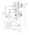
図1は、本発明の実施形態に係る制御装置が適用される車両の概略構成を示している。車両は、駆動源としてエンジン1を備える。エンジン1の出力回転は、トルクコンバータ2、前後進切換機構3、変速機4及び終減速機構5を介して駆動輪6へと伝達される。
FIG. 1 shows a schematic configuration of a vehicle to which a control device according to an embodiment of the present invention is applied. The vehicle includes an
エンジン1は、ガソリン、軽油等を燃料とする内燃機関であり、後述するコントローラ100によって回転速度及びトルクが制御される。また、後述するセーリングストップ中は、エンジン1への燃料供給が停止されるとともに変速機4がニュートラル状態(動力遮断状態)に制御され、エンジン1は回転を停止する。
The
エンジン1には、エンジン1の駆動力の一部を利用して駆動されるオルタネータ11が取り付けられている。オルタネータ11が発生する電力は、後述するブレーキシステム8、パワーステアリングシステム9、電動オイルポンプ72、バッテリ12等に分配される。エンジン1が停止しオルタネータ11の発電も停止した場合は、オルタネータ11が発電する電力に代えてバッテリ12に蓄えられている電力がブレーキシステム8、パワーステアリングシステム9、電動オイルポンプ72等に分配される。
An
トルクコンバータ2は、ロックアップクラッチ21を有するトルクコンバータである。ロックアップクラッチ21は、車速に基づき、後述するコントローラ100によって締結解放が制御される。ロックアップクラッチ21が解放された状態では、トルクコンバータ2は、エンジン1から入力されるトルクを増幅して出力する。ロックアップクラッチ21が締結された状態では、トルクコンバータ2の入力軸と出力軸が直結され、トルクコンバータ2の滑りに起因する伝達ロスが抑えられる。
The torque converter 2 is a torque converter having a
前後進切換機構3は、ダブルピニオン遊星歯車機構31、前進クラッチ32及び後退ブレーキ33とで構成される。前後進切換機構3は、前進クラッチ32を締結し後退ブレーキ33を解放すると回転方向を維持したまま回転を伝達する前進状態が実現され、前進クラッチ32を解放し後退ブレーキ33を締結すると回転方向を反転して回転を伝達する後退状態が実現される。また、前進クラッチ32及び後退ブレーキ33を解放すると、変速機4のニュートラル状態が実現され、エンジン1がパワートレインから切り離された動力遮断状態が実現される。
The forward /
変速機4は、プライマリプーリ41と、セカンダリプーリ42と、プライマリプーリ41とセカンダリプーリ42との間に掛け渡されるベルト43とで構成される無段変速機である。プライマリプーリ41及びセカンダリプーリ42の溝幅をそれぞれ変更すると、プライマリプーリ41及びセカンダリプーリ42とベルト43との接触半径が変更され、変速機4の変速比が無段階に変化する。変速機4の変速比は、後述するコントローラ100によって制御される。
The
プライマリプーリ41は、固定プーリ41aと、固定プーリ41aに対向して配置され、背面に油室41cを有する可動プーリ41bとで構成される。同様に、セカンダリプーリ42は、固定プーリ42aと、固定プーリ42aに対向して配置され、背面に油室42cを有する可動プーリ42bとで構成される。
The
プライマリプーリ41及びセカンダリプーリ42の溝幅は、油室41c、42cに供給される油圧を変化させ、可動プーリ41b、42bを変位させることによって変更される。油室41c、42cに供給される油圧は、油圧回路7から供給される。
The groove widths of the
油圧回路7は、メカオイルポンプ71及び電動オイルポンプ72の少なくとも一方が発生する油圧をレギュレータ弁73によってライン圧に調整する。さらに、ライン圧を、第1調圧弁74、第2調圧弁75によってプライマリ圧及びセカンダリ圧に調整する。プライマリ圧及びセカンダリ圧は、それぞれプライマリプーリ41の油室41c、セカンダリプーリ42の油室42cへと供給され、これによって変速機4の変速が行われ、又は、変速比が維持される。
The
メカオイルポンプ71はエンジン1の駆動力の一部を利用して駆動され、エンジン1が停止するとメカオイルポンプ71も停止する。したがって、エンジン1停止中は、変速機4や前後進切換機構3で必要とされる油圧は、バッテリ12から供給される電力によって駆動される電動オイルポンプ72によって発生させる。電動オイルポンプ72で必要とされる電力は、必要とされる油圧が高いほど電動オイルポンプ72の回転速度を高める必要があることから、必要とされる油圧が高いほど増大する。
The mechanical oil pump 71 is driven by utilizing a part of the driving force of the
また、変速機4の変速比は、車速及びアクセルペダルの踏み込み量に基づき図2に示す変速マップを参照して変速機4の目標入力回転速度を設定し、これが達成されるよう制御される。なお、図2では、理解を容易にするために、アクセルペダルが最大まで踏み込まれた場合の変速線(アクセルON変速線)とアクセルペダルが踏み込まれていない場合の変速線(アクセルOFF変速線)のみを示している。実際の変速マップには、アクセルペダルが部分的に踏み込まれた場合の変速線がアクセルON変速線とアクセルOFF変速線との間に複数設定されている。
The gear ratio of the
変速機4の入力回転速度を出力回転速度(∝車速)で割った値が変速機4の変速比であるので、変速機4の目標入力回転速度を設定することと変速機4の目標変速比を設定することとは等価である。
Since the value obtained by dividing the input rotation speed of the
終減速機構5は、複数の歯車列51及び差動歯車機構52とで構成され、変速機4の出力回転を駆動輪6に伝達する。
The final
また、車両には、駆動輪6及び図示しない従動輪を制動するためのブレーキシステム8が設けられている。
Further, the vehicle is provided with a
ブレーキシステム8は、各車輪に取り付けられる液圧式ブレーキ81と、ドライバによるブレーキペダルの踏み込みを検出するブレーキセンサ82と、液圧式ブレーキ81のブレーキ液圧を調整する液圧調整ユニット83とで構成される。
The
ドライバによるブレーキペダルの踏み込みが検出されると、オルタネータ11又はバッテリ12からの電力によって液圧調整ユニット83内のブレーキアクチュエータ84が作動する。ブレーキアクチュエータ84は、マスタシリンダのピストンを変位させてブレーキ液圧をブレーキペダルの踏み込み量に応じた液圧に調整する。ブレーキシステム8は、この他、後述するように自動ブレーキを実行する場合にも作動する。
When depression of the brake pedal by the driver is detected, the
パワーステアリングシステム9は、オルタネータ11又はバッテリ12から供給される電力によって駆動されるモータ91によってドライバの操舵をアシストする。
The
コントローラ100は、CANを介して互いに通信可能に接続された複数のコントロールユニット(エンジンコントロールユニット、変速機コントロールユニット、ボディコントロールモジュール等)で構成される。各コントロールユニットは、マイクロプロセッサ、メモリ、入出力インターフェース等で構成される。
The
コントローラ100は、車両の運転状態を検出する各種センサからの入力に基づき車両の運転状態を判断し、エンジン1、ロックアップクラッチ21、前後進切換機構3、変速機4、ブレーキシステム8、パワーステアリングシステム9、電動オイルポンプ72を統合的に制御する。各種センサには、車速センサ101、アクセル開度センサ102、ブレーキセンサ82、エンジン回転速度センサ103、変速機入力回転速度センサ104、レンジ選択スイッチ105等が含まれる。
The
また、コントローラ100には、車両の進行方向前方を撮像するカメラ106が接続されている。コントローラ100は、カメラ106によって撮像された画像を解析することによって車両前方にある物体(車両、人、障害物等)を検知する。そして、コントローラ100は、車両前方にある物体と接触する可能性があると判断される場合には、音、メッセージ等からなる警告をドライバに対して発し、警告を受けてもなおドライバがブレーキペダルを踏み込まない場合には液圧式ブレーキ81を自動で作動させる(自動ブレーキ)。車両前方にある物体の検出方法はカメラ106を用いる方法に限定されず、カメラ106に代えて、又は、カメラ106に加えて、赤外線装置、ミリ波レーダを利用する検出方法であってもよい。
Further, the
また、コントローラ100は、アクセルOFFで惰性走行をしているコースト状態において、エンジン1を停止するとともに変速機4をニュートラル状態として、エンジン1の回転を完全に停止させるセーリングストップ制御を実行する。セーリングストップ中は、エンジン1の連れ回りがなくなってエンジンブレーキが駆動輪6に作用しなくなるので、車両の燃費を向上させることができる。
Further, the
具体的には、コントローラ100は、前進レンジが選択され、車速が設定車速(中〜高車速)以上であり、アクセルペダル及びブレーキペダルが踏み込まれていないと、セーリングストップ開始条件が成立したと判断し、エンジン1への燃料供給を停止するとともに前後進切換機構3の前進クラッチ32及び後退ブレーキ33を解放して変速機4をニュートラル状態にする。
Specifically, the
ところで、セーリングストップ中は、エンジン1が停止し、オルタネータ11が発電を停止するので、オルタネータ11に代えてバッテリ12からブレーキシステム8、パワーステアリングシステム9、電動オイルポンプ72等に電力が分配される。
By the way, during the sailing stop, the
電力の分配は、例えば、バッテリ12の最大出力をXとし、n1、n2を任意の正の数とすると、ブレーキシステム8に最大でX/n1を配分し、パワーステアリングシステム9に最大でX/n2を配分し、残りの部位には最大でX−(X/n1+X/n2)を配分することで行われる。
For example, when the maximum output of the
その一方で、自動ブレーキ実行中は、安全上、ブレーキシステム8及びパワーステアリングシステム9への電力配分を優先し、自動ブレーキ実行中に確実に液圧式ブレーキ81が作動し、かつ、ステアリング操作が可能になるようにしている。上記例であれば、自動ブレーキ実行中は、n1、n2がそれぞれ自動ブレーキ非実行時よりも小さな値に変更される。
On the other hand, during automatic brake execution, for safety, priority is given to power distribution to the
したがって、セーリングストップ中に自動ブレーキが実行されると、ブレーキシステム8及びパワーステアリングシステム9への電力配分を優先させたことで、変速機4で利用可能な最大電力(瞬間的なエネルギーの最大値)が制限されることになる。
Therefore, when automatic braking is executed during sailing stop, priority is given to power distribution to the
このような状況では、車両の急減速に伴い変速機4を速やかにダウンシフトさせる必要が生じても、電動オイルポンプ72からの電力要求を満たすことができず、変速機4の変速速度(単位時間当たりの変速比の変化量)が制限される。この結果、変速機4のダウンシフトが不十分になり、自動ブレーキ解除後の再発進又は再加速時に必要な駆動力が得られなくなる可能性がある。
In such a situation, even if it is necessary to quickly downshift the
エンジン1を再始動すればオルタネータ11が発電を再開し、また、メカオイルポンプ71が駆動されるので、このような問題を解消することができる可能性がある。しかしながら、エンジン1の再始動に使われるスタータモータは消費電力が大きく、また、エンジン1の再始動には時間を要し、運転状況によってはエンジン1の再始動自体が禁止されているため、上記問題を解消できない可能性がある。これらの点を鑑みれば、バッテリ12から供給可能な電力で所望の変速を実現できるようにするのが好ましい。
If the
そこで、本実施形態では、セーリングストップ中に自動ブレーキが実行される場合は、アクセルOFF変速線を高回転側に変更する(以下、変更前のアクセルOFF変速線を「第1アクセルOFF変速線」、変更後のアクセルOFF変速線を「第2アクセルOFF変速線」という。)。 Therefore, in the present embodiment, when the automatic braking is executed during the sailing stop, the accelerator OFF shift line is changed to the high rotation side (hereinafter, the accelerator OFF shift line before the change is the “first accelerator OFF shift line”). , And the changed accelerator off shift line is referred to as "second accelerator off shift line".)
アクセルOFF変速線を高回転側に変更とは、各車速に対する目標入力回転速度を当該変速線が使用される車速域においてより高い値に変更することであり、変速マップ上では、図3に示される様に、変速線を上側(高回転側)にシフトさせることである。 Changing the accelerator-off shift line to the high rotation side means changing the target input rotation speed for each vehicle speed to a higher value in the vehicle speed range in which the shift line is used, and is shown in FIG. 3 on the shift map. As described above, the shift line is shifted to the upper side (high rotation side).
アクセルOFF変速線が第1アクセルOFF変速線から第2アクセルOFF変速線に変更されると、変速機4の目標入力回転速度がN1からN2にステップ的に変更され、これによって変速機4の目標変速比がLowにステップ的に変更され、変速開始当初のダウンシフト量が増やされる。これにより、自動ブレーキによる急減速が起こる前にダウンシフトを一部前倒して実行させ、その後の急減速中のダウンシフト量を減らして変速速度を下げ、これによって変速中に変速機4が必要とする最大電力を抑制する。
When the accelerator OFF shift line is changed from the first accelerator OFF shift line to the second accelerator OFF shift line, the target input rotation speed of the
図4は、これを実現するためのコントローラ100の制御内容を説明するためのフローチャートである。
FIG. 4 is a flowchart for explaining the control contents of the
これについて説明すると、ステップS1では、コントローラ100は、セーリングストップ中か判断する。セーリングストップ中か否かはセーリングストップ開始時に所定のフラグに特定の値(例えば、1)をセットし、セーリングストップ解除時に別の特定の値(例えば、0)をセットするようにしておき、当該フラグの値を参照することによって判断することができる。セーリングストップ中であれば処理がステップS2に進む。
To explain this, in step S1, the
ステップS2では、コントローラ100は、アクセルOFF時の変速線として第1アクセルOFF変速線(図3参照)を選択する。これにより、車速及び入力回転速度で決まる変速機4の動作点が第1アクセルOFF変速線に沿って移動するよう変速機4の変速が行われる。
In step S2, the
ステップS3では、コントローラ100は、セーリングストップ解除条件が成立しているか判断する。セーリングストップ解除条件は、例えば、セーリングストップ中にアクセルペダル又はブレーキペダルが踏み込まれると成立する。
In step S3, the
セーリングストップ解除条件が成立すると、処理がステップS4に進み、コントローラ100はセーリングストップを解除する。すなわち、エンジン1を始動し、前進クラッチ32を締結する。
When the sailing stop cancellation condition is satisfied, the process proceeds to step S4, and the
一方、ステップS3でセーリングストップ解除条件が成立していないと、処理がステップS5に進む。 On the other hand, if the sailing stop cancellation condition is not satisfied in step S3, the process proceeds to step S5.
ステップS5では、コントローラ100は、自動ブレーキの実行を検知したか判断する。自動ブレーキ実行中か否かは自動ブレーキ実行時に所定のフラグに特定の値(例えば、1)をセットし、自動ブレーキ解除時に別の特定の値(例えば、0)をセットするようにしておき、当該フラグの値を参照することによって判断することができる。
In step S5, the
自動ブレーキの実行を検知した場合は処理がステップS6に進み、そうでなければ処理がステップS2に戻る。 If the execution of automatic braking is detected, the process proceeds to step S6, and if not, the process returns to step S2.
ステップS6では、コントローラ100は、エンジン1の再始動を禁止する。
In step S6, the
ステップS7では、コントローラ100は、アクセルOFF時の変速線として第1アクセルOFF変速線よりも高回転側に設定される第2アクセルOFF変速線(図3参照)を選択する。これにより、変速機4の目標入力回転速度がN1からN2に変更され、第1アクセルOFF変速線上ないしその近傍にあった変速機4の動作点は、図5に実線で示す様に、自動ブレーキの実行が検知された時点の位置Xから第2アクセルOFF変速線に向けて移動し、自動ブレーキによる車両の急減速に先立ち変速機4のダウンシフトが行われる。
In step S7, the
その後は、車両の急減速に伴い高い変速速度で変速機4のダウンシフトが行われ、変速機4の動作点は原点Oに向けて移動する。なお、図中二点鎖線は変速線を変更しなかった場合の変速機4の動作点の挙動である。
After that, the
ステップS7の処理はステップS8で自動ブレーキが解除されたと判断されるまで継続される。 The process of step S7 is continued until it is determined in step S8 that the automatic brake is released.
ステップS8で自動ブレーキが解除されたと判断されると、処理がステップS9に進み、コントローラ100は、エンジン1を再始動し、前進クラッチ32を締結する(セーリングストップ解除)。
If it is determined in step S8 that the automatic braking has been released, the process proceeds to step S9, and the
図6は、セーリングストップ中に自動ブレーキが実行された場合の様子を示している。実線は本実施形態(変速線の変更あり)、破線は比較例(変速線の変更なし)を示している。これを参照しながら上記制御を行うことによる作用効果について説明する。 FIG. 6 shows a state in which the automatic braking is executed during the sailing stop. The solid line shows the present embodiment (change of the shift line), and the broken line shows the comparative example (without change of the shift line). The effect of the above control will be described with reference to this.
自動ブレーキ実行前の状態はセーリングストップ中であり、この状態では、車速が徐々に低下し、これに応じて変速機4のダウンシフトが緩やかに行われる。この時に使われる変速線は第1アクセルOFF変速線(図2)である。
The state before execution of automatic braking is sailing stop, and in this state, the vehicle speed gradually decreases, and accordingly, the downshift of the
自動ブレーキの実行が開始されてその実行が検知されると、変速線が第1アクセルOFF変速線から第2アクセルOFF変速線に変更される。変速線の変更によって目標入力回転速度が高回転側に変更されることで、車両の急減速に先立ち、変速機4のダウンシフトが一部前倒して行われる。自動ブレーキによる車両の急減速は、ブレーキアクチュエータ84が動作を開始してから駆動輪6に制動力が実際に作用するまでに若干の遅れ時間があるので、自動ブレーキの実行が検知されたタイミングより遅れて発生する。
When the execution of the automatic braking is started and detected, the shift line is changed from the first accelerator-OFF shift line to the second accelerator-OFF shift line. By changing the target input rotation speed to the high rotation side by changing the shift line, the downshift of the
その後、車両の急減速に合わせて変速機4のダウンシフトが高い変速速度で行われるが、急減速前のダウンシフト量を増やしたことで急減速中のダウンシフト量が減り、急減速中の変速機4の変速速度が抑えられるので、変速機4で必要とされる最大電力(瞬間的な最大エネルギー)が抑えられる。
After that, the downshift of the
これにより、自動ブレーキが実行されることで変速機4に供給可能な最大電力が制限されたとしても、変速機4の消費電力を最大電力以下に抑えつつ変速機4を十分にダウンシフトさせることができ、自動ブレーキ解除後の再発進又は再加速時に必要な駆動力が得られなくなるのを防止することができる。
As a result, even if the maximum electric power that can be supplied to the
また、セーリングストップ中に自動ブレーキが実行された場合はエンジン1の再始動を行わず、自動ブレーキが解除されてからエンジン1を再始動するようにしたので、エンジン1を再始動するために電力が消費されて電力不足に起因するダウンシフト不足の問題が生じやすくなるのを防ぐことができる。
Further, when the automatic braking is executed during the sailing stop, the
以上、本発明の実施形態について説明したが、上記実施形態は本発明の適用例の一つを示したものに過ぎず、本発明の技術的範囲を上記実施形態の具体的構成に限定する趣旨ではない。 Although the embodiments of the present invention have been described above, the above embodiments merely show one application example of the present invention, and the technical scope of the present invention is limited to the specific configuration of the above embodiments. is not.
例えば、本実施形態では駆動源をエンジンとしたが、駆動源は、エンジンとモータとの組み合わせ、あるいはモータとしてもよい。この場合、セーリングストップ中に自動ブレーキが実行された場合は、駆動源(エンジン1及び/又はモータ)の再始動を行わず、自動ブレーキが解除されてから駆動源を再始動するようにしたので、駆動源を再始動するために電力が消費されて電力不足に起因するダウンシフト不足の問題が生じやすくなるのを防ぐことができる。
For example, although the drive source is the engine in the present embodiment, the drive source may be a combination of the engine and the motor or a motor. In this case, if the automatic braking is executed during the sailing stop, the drive source (
本願は2016年5月25日に日本国特許庁に出願された特願2016−104277に基づく優先権を主張し、この出願の全ての内容は参照により本明細書に組み込まれる。 The present application claims priority based on Japanese Patent Application No. 2016-104277 filed with the Japan Patent Office on May 25, 2016, the entire contents of which are incorporated herein by reference.
Claims (7)
前記車両の走行中に前記駆動源の停止を行うセーリングストップ中にブレーキペダルが踏み込まれていない場合に車輪に取り付けられたブレーキを自動で作動させる自動ブレーキの実行を検知すると、前記駆動源と前記車輪との間の動力を遮断した状態で前記無段変速機のダウンシフトを行うと共に、前記車輪に前記ブレーキの制動力が作用する前に前記無段変速機の変速線を高回転側に変更する制御部を有する、
車両の制御装置。 A control device for a vehicle having a drive source and a continuously variable transmission,
When the execution of the automatic brake that automatically operates the brake attached to the wheel is detected when the brake pedal is not depressed during the sailing stop for stopping the drive source while the vehicle is traveling, the drive source and the The downshift of the continuously variable transmission is performed in a state where the power between the continuously variable transmission and the wheels is cut off, and the shift line of the continuously variable transmission is changed to the high rotation side before the braking force of the brake acts on the wheels. Has a control unit to
Vehicle control device.
前記車両の走行中に前記駆動源の停止を行うセーリングストップ中にブレーキペダルが踏み込まれていない場合に車輪に取り付けられたブレーキを自動で作動させる自動ブレーキの実行を検知すると、前記駆動源と前記車輪との間の動力を遮断した状態で前記無段変速機のダウンシフトを行うと共に、前記車輪に前記ブレーキの制動力が作用する前に前記無段変速機の変速線を変更することにより前記無段変速機の入力回転速度を増加させる制御部を有する、
車両の制御装置。 A control device for a vehicle having a drive source and a continuously variable transmission,
When the execution of the automatic brake that automatically operates the brake attached to the wheel is detected when the brake pedal is not depressed during the sailing stop for stopping the drive source while the vehicle is traveling, the drive source and the The downshift of the continuously variable transmission is performed in a state in which power between the continuously variable transmission and the wheels is cut off, and the shift line of the continuously variable transmission is changed before the braking force of the brake acts on the wheels. A control unit for increasing the input rotation speed of the continuously variable transmission;
Vehicle control device.
前記制御部は、前記自動ブレーキの解除後に前記駆動源を再始動する、
車両の制御装置。 The vehicle control device according to claim 1 or 2,
The control unit restarts the drive source after releasing the automatic brake,
Vehicle control device.
前記車両は、電動オイルポンプを有し、
前記制御部は、前記セーリングストップ中に前記自動ブレーキの実行を検知すると、前記電動オイルポンプにより前記無段変速機の変速を行う、
車両の制御装置。 The vehicle control device according to claim 1 or 2,
The vehicle has an electric oil pump,
The control unit shifts the continuously variable transmission by the electric oil pump when detecting execution of the automatic braking during the sailing stop,
Vehicle control device.
前記制御部は、前記セーリングストップ中に前記ブレーキペダルが踏み込まれていない場合に前記車輪に取り付けられた前記ブレーキを自動で作動させる前記自動ブレーキの実行を検知すると、前記車輪に前記ブレーキの制動力が作用する前に前記電動オイルポンプの回転速度を高める、
車両の制御装置。 The vehicle control device according to claim 4,
When the control unit detects execution of the automatic brake that automatically operates the brake attached to the wheel when the brake pedal is not depressed during the sailing stop, the braking force of the brake is applied to the wheel. Increase the speed of rotation of the electric oil pump before
Vehicle control device.
前記車両の走行中に前記駆動源の停止を行うセーリングストップ中にブレーキペダルが踏み込まれていない場合に車輪に取り付けられたブレーキを自動で作動させる自動ブレーキの実行を検知すると、前記駆動源と前記車輪との間の動力を遮断した状態で前記無段変速機のダウンシフトを行うと共に、前記車輪に前記ブレーキの制動力が作用する前に前記無段変速機の変速線を高回転側に変更する、
車両の制御方法。 A control method for a vehicle having a drive source and a continuously variable transmission, comprising:
When the execution of the automatic brake that automatically operates the brake attached to the wheel is detected when the brake pedal is not depressed during the sailing stop for stopping the drive source while the vehicle is traveling, the drive source and the The downshift of the continuously variable transmission is performed in a state where the power between the continuously variable transmission and the wheels is cut off, and the shift line of the continuously variable transmission is changed to the high rotation side before the braking force of the brake acts on the wheels. To do
Vehicle control method.
前記車両の走行中に前記駆動源の停止を行うセーリングストップ中にブレーキペダルが踏み込まれていない場合に車輪に取り付けられたブレーキを自動で作動させる自動ブレーキの実行を検知すると、前記駆動源と前記車輪との間の動力を遮断した状態で前記無段変速機のダウンシフトを行うと共に、前記車輪に前記ブレーキの制動力が作用する前に前記無段変速機の変速線を変更することにより前記無段変速機の入力回転速度を増加させる、
車両の制御方法。 A control method for a vehicle having a drive source and a continuously variable transmission, comprising:
When the execution of the automatic brake that automatically operates the brake attached to the wheel is detected when the brake pedal is not depressed during the sailing stop for stopping the drive source while the vehicle is traveling, the drive source and the The downshift of the continuously variable transmission is performed in a state in which power between the continuously variable transmission and the wheels is cut off, and the shift line of the continuously variable transmission is changed before the braking force of the brake acts on the wheels. Increase the input speed of the continuously variable transmission,
Vehicle control method.
Applications Claiming Priority (3)
| Application Number | Priority Date | Filing Date | Title |
|---|---|---|---|
| JP2016104277 | 2016-05-25 | ||
| JP2016104277 | 2016-05-25 | ||
| PCT/JP2017/014942 WO2017203874A1 (en) | 2016-05-25 | 2017-04-12 | Control device and control method for vehicle comprising continuously variable transmission |
Publications (2)
| Publication Number | Publication Date |
|---|---|
| JPWO2017203874A1 JPWO2017203874A1 (en) | 2019-03-28 |
| JP6697548B2 true JP6697548B2 (en) | 2020-05-20 |
Family
ID=60411969
Family Applications (1)
| Application Number | Title | Priority Date | Filing Date |
|---|---|---|---|
| JP2018519138A Active JP6697548B2 (en) | 2016-05-25 | 2017-04-12 | Control device and control method for vehicle equipped with continuously variable transmission |
Country Status (5)
| Country | Link |
|---|---|
| US (1) | US10962111B2 (en) |
| JP (1) | JP6697548B2 (en) |
| KR (1) | KR102047617B1 (en) |
| CN (1) | CN109073072B (en) |
| WO (1) | WO2017203874A1 (en) |
Families Citing this family (4)
| Publication number | Priority date | Publication date | Assignee | Title |
|---|---|---|---|---|
| JP6746633B2 (en) * | 2018-06-22 | 2020-08-26 | 本田技研工業株式会社 | Collision mitigation control device |
| US11738737B2 (en) * | 2019-06-24 | 2023-08-29 | Jatco Ltd | Control device for vehicle and control method for vehicle |
| CN111412097B (en) * | 2020-03-04 | 2022-08-02 | 吉利汽车研究院(宁波)有限公司 | Vehicle auxiliary starting system and method |
| JP7241124B2 (en) * | 2021-04-21 | 2023-03-16 | 本田技研工業株式会社 | Control device and control method for continuously variable transmission for vehicle |
Family Cites Families (14)
| Publication number | Priority date | Publication date | Assignee | Title |
|---|---|---|---|---|
| JPS5973651A (en) * | 1982-10-21 | 1984-04-25 | Fuji Heavy Ind Ltd | Control device of stepless transmission |
| JP2003259504A (en) * | 2002-03-06 | 2003-09-12 | Nissan Motor Co Ltd | Braking controller |
| EP1541400B1 (en) * | 2002-09-13 | 2006-08-16 | Honda Giken Kogyo Kabushiki Kaisha | Hybrid vehicle |
| JP4193600B2 (en) | 2003-06-11 | 2008-12-10 | 日産自動車株式会社 | Automatic brake control device |
| JP2006094589A (en) * | 2004-09-21 | 2006-04-06 | Toyota Motor Corp | Vehicle acceleration and deceleration controller |
| JP2006137392A (en) * | 2004-11-15 | 2006-06-01 | Toyota Motor Corp | Vehicle deceleration controller |
| JP5309633B2 (en) | 2007-11-16 | 2013-10-09 | アイシン・エィ・ダブリュ株式会社 | Vehicle control apparatus, vehicle control method, and computer program |
| JP5082943B2 (en) * | 2008-03-10 | 2012-11-28 | 日産自動車株式会社 | Shift control device for continuously variable transmission for vehicle |
| JP5526005B2 (en) * | 2010-11-25 | 2014-06-18 | ジヤトコ株式会社 | Coast stop vehicle and coast stop vehicle control method |
| JP2013213557A (en) | 2012-04-03 | 2013-10-17 | Toyota Motor Corp | Control device of vehicle |
| WO2014021117A1 (en) * | 2012-07-31 | 2014-02-06 | ジヤトコ株式会社 | Automatic transmission for vehicle |
| JP6385167B2 (en) * | 2014-07-08 | 2018-09-05 | ジヤトコ株式会社 | Drive mechanism |
| WO2016021431A1 (en) * | 2014-08-07 | 2016-02-11 | 日立オートモティブシステムズ株式会社 | Control device for vehicles |
| US10556591B2 (en) * | 2016-02-29 | 2020-02-11 | Hitachi Automotive Systems, Ltd. | Vehicle control device |
-
2017
- 2017-04-12 JP JP2018519138A patent/JP6697548B2/en active Active
- 2017-04-12 CN CN201780026115.XA patent/CN109073072B/en active Active
- 2017-04-12 US US16/303,905 patent/US10962111B2/en active Active
- 2017-04-12 KR KR1020187030878A patent/KR102047617B1/en active IP Right Grant
- 2017-04-12 WO PCT/JP2017/014942 patent/WO2017203874A1/en active Application Filing
Also Published As
| Publication number | Publication date |
|---|---|
| US20200318736A1 (en) | 2020-10-08 |
| CN109073072A (en) | 2018-12-21 |
| US10962111B2 (en) | 2021-03-30 |
| JPWO2017203874A1 (en) | 2019-03-28 |
| CN109073072B (en) | 2020-05-22 |
| WO2017203874A1 (en) | 2017-11-30 |
| KR20180122727A (en) | 2018-11-13 |
| KR102047617B1 (en) | 2019-11-21 |
Similar Documents
| Publication | Publication Date | Title |
|---|---|---|
| JP5915496B2 (en) | Vehicle travel control device | |
| JP6697548B2 (en) | Control device and control method for vehicle equipped with continuously variable transmission | |
| US9834193B2 (en) | Vehicle control apparatus | |
| US9562480B2 (en) | Automatic engine-stop control device for vehicle | |
| EP3179125B1 (en) | Vehicle control device, and vehicle control method | |
| JP6241424B2 (en) | Vehicle control device | |
| JP6130367B2 (en) | Vehicle control device | |
| JP2007331533A (en) | Vehicle control device | |
| JP5751335B2 (en) | Engine start system | |
| JP6367516B2 (en) | Vehicle travel control device | |
| JP5862803B2 (en) | Transmission control apparatus and control method | |
| US10501083B2 (en) | Vehicle control device and vehicle control method | |
| JP5218161B2 (en) | Control device for hybrid vehicle | |
| JP6446278B2 (en) | Coast stop control device | |
| JP6741151B2 (en) | Control method and control device for hybrid vehicle | |
| JP2015034584A (en) | Fly wheel regeneration system and its control method | |
| JP5971407B2 (en) | Control device for hybrid vehicle | |
| JP7169058B2 (en) | vehicle controller | |
| JP2017222298A (en) | Drive force controlling method and drive force controlling device for vehicle | |
| JP6350676B2 (en) | Control device for vehicle drive device | |
| JP6743329B2 (en) | Control device for hybrid vehicle | |
| JP5928288B2 (en) | Control device for clutch | |
| WO2015019783A1 (en) | Flywheel regeneration system, and method of controlling same | |
| WO2019069444A1 (en) | Method for controlling internal combustion engine and device for controlling internal combustion engine | |
| JP2018114831A (en) | Vehicle and method for controlling vehicle |
Legal Events
| Date | Code | Title | Description |
|---|---|---|---|
| A521 | Written amendment |
Free format text: JAPANESE INTERMEDIATE CODE: A523 Effective date: 20181011 |
|
| A529 | Written submission of copy of amendment under section 34 (pct) |
Free format text: JAPANESE INTERMEDIATE CODE: A5211 Effective date: 20181011 |
|
| A621 | Written request for application examination |
Free format text: JAPANESE INTERMEDIATE CODE: A621 Effective date: 20181011 |
|
| A131 | Notification of reasons for refusal |
Free format text: JAPANESE INTERMEDIATE CODE: A131 Effective date: 20190813 |
|
| A521 | Written amendment |
Free format text: JAPANESE INTERMEDIATE CODE: A523 Effective date: 20190910 |
|
| A131 | Notification of reasons for refusal |
Free format text: JAPANESE INTERMEDIATE CODE: A131 Effective date: 20191008 |
|
| A521 | Written amendment |
Free format text: JAPANESE INTERMEDIATE CODE: A523 Effective date: 20191114 |
|
| TRDD | Decision of grant or rejection written | ||
| A01 | Written decision to grant a patent or to grant a registration (utility model) |
Free format text: JAPANESE INTERMEDIATE CODE: A01 Effective date: 20200407 |
|
| A61 | First payment of annual fees (during grant procedure) |
Free format text: JAPANESE INTERMEDIATE CODE: A61 Effective date: 20200424 |
|
| R150 | Certificate of patent or registration of utility model |
Ref document number: 6697548 Country of ref document: JP Free format text: JAPANESE INTERMEDIATE CODE: R150 |