EP1541400B1 - Hybrid vehicle - Google Patents
Hybrid vehicle Download PDFInfo
- Publication number
- EP1541400B1 EP1541400B1 EP03795201A EP03795201A EP1541400B1 EP 1541400 B1 EP1541400 B1 EP 1541400B1 EP 03795201 A EP03795201 A EP 03795201A EP 03795201 A EP03795201 A EP 03795201A EP 1541400 B1 EP1541400 B1 EP 1541400B1
- Authority
- EP
- European Patent Office
- Prior art keywords
- generator
- motor
- engine
- clutch
- driving force
- Prior art date
- Legal status (The legal status is an assumption and is not a legal conclusion. Google has not performed a legal analysis and makes no representation as to the accuracy of the status listed.)
- Expired - Fee Related
Links
Images


Classifications
-
- B—PERFORMING OPERATIONS; TRANSPORTING
- B60—VEHICLES IN GENERAL
- B60W—CONJOINT CONTROL OF VEHICLE SUB-UNITS OF DIFFERENT TYPE OR DIFFERENT FUNCTION; CONTROL SYSTEMS SPECIALLY ADAPTED FOR HYBRID VEHICLES; ROAD VEHICLE DRIVE CONTROL SYSTEMS FOR PURPOSES NOT RELATED TO THE CONTROL OF A PARTICULAR SUB-UNIT
- B60W10/00—Conjoint control of vehicle sub-units of different type or different function
- B60W10/10—Conjoint control of vehicle sub-units of different type or different function including control of change-speed gearings
-
- B—PERFORMING OPERATIONS; TRANSPORTING
- B60—VEHICLES IN GENERAL
- B60K—ARRANGEMENT OR MOUNTING OF PROPULSION UNITS OR OF TRANSMISSIONS IN VEHICLES; ARRANGEMENT OR MOUNTING OF PLURAL DIVERSE PRIME-MOVERS IN VEHICLES; AUXILIARY DRIVES FOR VEHICLES; INSTRUMENTATION OR DASHBOARDS FOR VEHICLES; ARRANGEMENTS IN CONNECTION WITH COOLING, AIR INTAKE, GAS EXHAUST OR FUEL SUPPLY OF PROPULSION UNITS IN VEHICLES
- B60K17/00—Arrangement or mounting of transmissions in vehicles
- B60K17/04—Arrangement or mounting of transmissions in vehicles characterised by arrangement, location, or kind of gearing
- B60K17/10—Arrangement or mounting of transmissions in vehicles characterised by arrangement, location, or kind of gearing of fluid gearing
-
- B—PERFORMING OPERATIONS; TRANSPORTING
- B60—VEHICLES IN GENERAL
- B60K—ARRANGEMENT OR MOUNTING OF PROPULSION UNITS OR OF TRANSMISSIONS IN VEHICLES; ARRANGEMENT OR MOUNTING OF PLURAL DIVERSE PRIME-MOVERS IN VEHICLES; AUXILIARY DRIVES FOR VEHICLES; INSTRUMENTATION OR DASHBOARDS FOR VEHICLES; ARRANGEMENTS IN CONNECTION WITH COOLING, AIR INTAKE, GAS EXHAUST OR FUEL SUPPLY OF PROPULSION UNITS IN VEHICLES
- B60K6/00—Arrangement or mounting of plural diverse prime-movers for mutual or common propulsion, e.g. hybrid propulsion systems comprising electric motors and internal combustion engines ; Control systems therefor, i.e. systems controlling two or more prime movers, or controlling one of these prime movers and any of the transmission, drive or drive units Informative references: mechanical gearings with secondary electric drive F16H3/72; arrangements for handling mechanical energy structurally associated with the dynamo-electric machine H02K7/00; machines comprising structurally interrelated motor and generator parts H02K51/00; dynamo-electric machines not otherwise provided for in H02K see H02K99/00
- B60K6/20—Arrangement or mounting of plural diverse prime-movers for mutual or common propulsion, e.g. hybrid propulsion systems comprising electric motors and internal combustion engines ; Control systems therefor, i.e. systems controlling two or more prime movers, or controlling one of these prime movers and any of the transmission, drive or drive units Informative references: mechanical gearings with secondary electric drive F16H3/72; arrangements for handling mechanical energy structurally associated with the dynamo-electric machine H02K7/00; machines comprising structurally interrelated motor and generator parts H02K51/00; dynamo-electric machines not otherwise provided for in H02K see H02K99/00 the prime-movers consisting of electric motors and internal combustion engines, e.g. HEVs
- B60K6/22—Arrangement or mounting of plural diverse prime-movers for mutual or common propulsion, e.g. hybrid propulsion systems comprising electric motors and internal combustion engines ; Control systems therefor, i.e. systems controlling two or more prime movers, or controlling one of these prime movers and any of the transmission, drive or drive units Informative references: mechanical gearings with secondary electric drive F16H3/72; arrangements for handling mechanical energy structurally associated with the dynamo-electric machine H02K7/00; machines comprising structurally interrelated motor and generator parts H02K51/00; dynamo-electric machines not otherwise provided for in H02K see H02K99/00 the prime-movers consisting of electric motors and internal combustion engines, e.g. HEVs characterised by apparatus, components or means specially adapted for HEVs
- B60K6/36—Arrangement or mounting of plural diverse prime-movers for mutual or common propulsion, e.g. hybrid propulsion systems comprising electric motors and internal combustion engines ; Control systems therefor, i.e. systems controlling two or more prime movers, or controlling one of these prime movers and any of the transmission, drive or drive units Informative references: mechanical gearings with secondary electric drive F16H3/72; arrangements for handling mechanical energy structurally associated with the dynamo-electric machine H02K7/00; machines comprising structurally interrelated motor and generator parts H02K51/00; dynamo-electric machines not otherwise provided for in H02K see H02K99/00 the prime-movers consisting of electric motors and internal combustion engines, e.g. HEVs characterised by apparatus, components or means specially adapted for HEVs characterised by the transmission gearings
-
- B—PERFORMING OPERATIONS; TRANSPORTING
- B60—VEHICLES IN GENERAL
- B60K—ARRANGEMENT OR MOUNTING OF PROPULSION UNITS OR OF TRANSMISSIONS IN VEHICLES; ARRANGEMENT OR MOUNTING OF PLURAL DIVERSE PRIME-MOVERS IN VEHICLES; AUXILIARY DRIVES FOR VEHICLES; INSTRUMENTATION OR DASHBOARDS FOR VEHICLES; ARRANGEMENTS IN CONNECTION WITH COOLING, AIR INTAKE, GAS EXHAUST OR FUEL SUPPLY OF PROPULSION UNITS IN VEHICLES
- B60K6/00—Arrangement or mounting of plural diverse prime-movers for mutual or common propulsion, e.g. hybrid propulsion systems comprising electric motors and internal combustion engines ; Control systems therefor, i.e. systems controlling two or more prime movers, or controlling one of these prime movers and any of the transmission, drive or drive units Informative references: mechanical gearings with secondary electric drive F16H3/72; arrangements for handling mechanical energy structurally associated with the dynamo-electric machine H02K7/00; machines comprising structurally interrelated motor and generator parts H02K51/00; dynamo-electric machines not otherwise provided for in H02K see H02K99/00
- B60K6/20—Arrangement or mounting of plural diverse prime-movers for mutual or common propulsion, e.g. hybrid propulsion systems comprising electric motors and internal combustion engines ; Control systems therefor, i.e. systems controlling two or more prime movers, or controlling one of these prime movers and any of the transmission, drive or drive units Informative references: mechanical gearings with secondary electric drive F16H3/72; arrangements for handling mechanical energy structurally associated with the dynamo-electric machine H02K7/00; machines comprising structurally interrelated motor and generator parts H02K51/00; dynamo-electric machines not otherwise provided for in H02K see H02K99/00 the prime-movers consisting of electric motors and internal combustion engines, e.g. HEVs
- B60K6/42—Arrangement or mounting of plural diverse prime-movers for mutual or common propulsion, e.g. hybrid propulsion systems comprising electric motors and internal combustion engines ; Control systems therefor, i.e. systems controlling two or more prime movers, or controlling one of these prime movers and any of the transmission, drive or drive units Informative references: mechanical gearings with secondary electric drive F16H3/72; arrangements for handling mechanical energy structurally associated with the dynamo-electric machine H02K7/00; machines comprising structurally interrelated motor and generator parts H02K51/00; dynamo-electric machines not otherwise provided for in H02K see H02K99/00 the prime-movers consisting of electric motors and internal combustion engines, e.g. HEVs characterised by the architecture of the hybrid electric vehicle
- B60K6/44—Series-parallel type
-
- B—PERFORMING OPERATIONS; TRANSPORTING
- B60—VEHICLES IN GENERAL
- B60K—ARRANGEMENT OR MOUNTING OF PROPULSION UNITS OR OF TRANSMISSIONS IN VEHICLES; ARRANGEMENT OR MOUNTING OF PLURAL DIVERSE PRIME-MOVERS IN VEHICLES; AUXILIARY DRIVES FOR VEHICLES; INSTRUMENTATION OR DASHBOARDS FOR VEHICLES; ARRANGEMENTS IN CONNECTION WITH COOLING, AIR INTAKE, GAS EXHAUST OR FUEL SUPPLY OF PROPULSION UNITS IN VEHICLES
- B60K6/00—Arrangement or mounting of plural diverse prime-movers for mutual or common propulsion, e.g. hybrid propulsion systems comprising electric motors and internal combustion engines ; Control systems therefor, i.e. systems controlling two or more prime movers, or controlling one of these prime movers and any of the transmission, drive or drive units Informative references: mechanical gearings with secondary electric drive F16H3/72; arrangements for handling mechanical energy structurally associated with the dynamo-electric machine H02K7/00; machines comprising structurally interrelated motor and generator parts H02K51/00; dynamo-electric machines not otherwise provided for in H02K see H02K99/00
- B60K6/20—Arrangement or mounting of plural diverse prime-movers for mutual or common propulsion, e.g. hybrid propulsion systems comprising electric motors and internal combustion engines ; Control systems therefor, i.e. systems controlling two or more prime movers, or controlling one of these prime movers and any of the transmission, drive or drive units Informative references: mechanical gearings with secondary electric drive F16H3/72; arrangements for handling mechanical energy structurally associated with the dynamo-electric machine H02K7/00; machines comprising structurally interrelated motor and generator parts H02K51/00; dynamo-electric machines not otherwise provided for in H02K see H02K99/00 the prime-movers consisting of electric motors and internal combustion engines, e.g. HEVs
- B60K6/50—Architecture of the driveline characterised by arrangement or kind of transmission units
- B60K6/52—Driving a plurality of drive axles, e.g. four-wheel drive
-
- B—PERFORMING OPERATIONS; TRANSPORTING
- B60—VEHICLES IN GENERAL
- B60K—ARRANGEMENT OR MOUNTING OF PROPULSION UNITS OR OF TRANSMISSIONS IN VEHICLES; ARRANGEMENT OR MOUNTING OF PLURAL DIVERSE PRIME-MOVERS IN VEHICLES; AUXILIARY DRIVES FOR VEHICLES; INSTRUMENTATION OR DASHBOARDS FOR VEHICLES; ARRANGEMENTS IN CONNECTION WITH COOLING, AIR INTAKE, GAS EXHAUST OR FUEL SUPPLY OF PROPULSION UNITS IN VEHICLES
- B60K6/00—Arrangement or mounting of plural diverse prime-movers for mutual or common propulsion, e.g. hybrid propulsion systems comprising electric motors and internal combustion engines ; Control systems therefor, i.e. systems controlling two or more prime movers, or controlling one of these prime movers and any of the transmission, drive or drive units Informative references: mechanical gearings with secondary electric drive F16H3/72; arrangements for handling mechanical energy structurally associated with the dynamo-electric machine H02K7/00; machines comprising structurally interrelated motor and generator parts H02K51/00; dynamo-electric machines not otherwise provided for in H02K see H02K99/00
- B60K6/20—Arrangement or mounting of plural diverse prime-movers for mutual or common propulsion, e.g. hybrid propulsion systems comprising electric motors and internal combustion engines ; Control systems therefor, i.e. systems controlling two or more prime movers, or controlling one of these prime movers and any of the transmission, drive or drive units Informative references: mechanical gearings with secondary electric drive F16H3/72; arrangements for handling mechanical energy structurally associated with the dynamo-electric machine H02K7/00; machines comprising structurally interrelated motor and generator parts H02K51/00; dynamo-electric machines not otherwise provided for in H02K see H02K99/00 the prime-movers consisting of electric motors and internal combustion engines, e.g. HEVs
- B60K6/50—Architecture of the driveline characterised by arrangement or kind of transmission units
- B60K6/54—Transmission for changing ratio
- B60K6/543—Transmission for changing ratio the transmission being a continuously variable transmission
-
- B—PERFORMING OPERATIONS; TRANSPORTING
- B60—VEHICLES IN GENERAL
- B60W—CONJOINT CONTROL OF VEHICLE SUB-UNITS OF DIFFERENT TYPE OR DIFFERENT FUNCTION; CONTROL SYSTEMS SPECIALLY ADAPTED FOR HYBRID VEHICLES; ROAD VEHICLE DRIVE CONTROL SYSTEMS FOR PURPOSES NOT RELATED TO THE CONTROL OF A PARTICULAR SUB-UNIT
- B60W10/00—Conjoint control of vehicle sub-units of different type or different function
- B60W10/04—Conjoint control of vehicle sub-units of different type or different function including control of propulsion units
- B60W10/08—Conjoint control of vehicle sub-units of different type or different function including control of propulsion units including control of electric propulsion units, e.g. motors or generators
-
- B—PERFORMING OPERATIONS; TRANSPORTING
- B60—VEHICLES IN GENERAL
- B60W—CONJOINT CONTROL OF VEHICLE SUB-UNITS OF DIFFERENT TYPE OR DIFFERENT FUNCTION; CONTROL SYSTEMS SPECIALLY ADAPTED FOR HYBRID VEHICLES; ROAD VEHICLE DRIVE CONTROL SYSTEMS FOR PURPOSES NOT RELATED TO THE CONTROL OF A PARTICULAR SUB-UNIT
- B60W10/00—Conjoint control of vehicle sub-units of different type or different function
- B60W10/30—Conjoint control of vehicle sub-units of different type or different function including control of auxiliary equipment, e.g. air-conditioning compressors or oil pumps
-
- F—MECHANICAL ENGINEERING; LIGHTING; HEATING; WEAPONS; BLASTING
- F16—ENGINEERING ELEMENTS AND UNITS; GENERAL MEASURES FOR PRODUCING AND MAINTAINING EFFECTIVE FUNCTIONING OF MACHINES OR INSTALLATIONS; THERMAL INSULATION IN GENERAL
- F16H—GEARING
- F16H57/00—General details of gearing
- F16H57/04—Features relating to lubrication or cooling or heating
- F16H57/0434—Features relating to lubrication or cooling or heating relating to lubrication supply, e.g. pumps ; Pressure control
-
- F—MECHANICAL ENGINEERING; LIGHTING; HEATING; WEAPONS; BLASTING
- F16—ENGINEERING ELEMENTS AND UNITS; GENERAL MEASURES FOR PRODUCING AND MAINTAINING EFFECTIVE FUNCTIONING OF MACHINES OR INSTALLATIONS; THERMAL INSULATION IN GENERAL
- F16H—GEARING
- F16H61/00—Control functions within control units of change-speed- or reversing-gearings for conveying rotary motion ; Control of exclusively fluid gearing, friction gearing, gearings with endless flexible members or other particular types of gearing
- F16H61/0021—Generation or control of line pressure
- F16H61/0025—Supply of control fluid; Pumps therefore
- F16H61/0031—Supply of control fluid; Pumps therefore using auxiliary pumps, e.g. pump driven by a different power source than the engine
-
- F—MECHANICAL ENGINEERING; LIGHTING; HEATING; WEAPONS; BLASTING
- F16—ENGINEERING ELEMENTS AND UNITS; GENERAL MEASURES FOR PRODUCING AND MAINTAINING EFFECTIVE FUNCTIONING OF MACHINES OR INSTALLATIONS; THERMAL INSULATION IN GENERAL
- F16H—GEARING
- F16H61/00—Control functions within control units of change-speed- or reversing-gearings for conveying rotary motion ; Control of exclusively fluid gearing, friction gearing, gearings with endless flexible members or other particular types of gearing
- F16H61/66—Control functions within control units of change-speed- or reversing-gearings for conveying rotary motion ; Control of exclusively fluid gearing, friction gearing, gearings with endless flexible members or other particular types of gearing specially adapted for continuously variable gearings
- F16H61/662—Control functions within control units of change-speed- or reversing-gearings for conveying rotary motion ; Control of exclusively fluid gearing, friction gearing, gearings with endless flexible members or other particular types of gearing specially adapted for continuously variable gearings with endless flexible members
- F16H61/66272—Control functions within control units of change-speed- or reversing-gearings for conveying rotary motion ; Control of exclusively fluid gearing, friction gearing, gearings with endless flexible members or other particular types of gearing specially adapted for continuously variable gearings with endless flexible members characterised by means for controlling the torque transmitting capability of the gearing
-
- B—PERFORMING OPERATIONS; TRANSPORTING
- B60—VEHICLES IN GENERAL
- B60K—ARRANGEMENT OR MOUNTING OF PROPULSION UNITS OR OF TRANSMISSIONS IN VEHICLES; ARRANGEMENT OR MOUNTING OF PLURAL DIVERSE PRIME-MOVERS IN VEHICLES; AUXILIARY DRIVES FOR VEHICLES; INSTRUMENTATION OR DASHBOARDS FOR VEHICLES; ARRANGEMENTS IN CONNECTION WITH COOLING, AIR INTAKE, GAS EXHAUST OR FUEL SUPPLY OF PROPULSION UNITS IN VEHICLES
- B60K17/00—Arrangement or mounting of transmissions in vehicles
- B60K17/34—Arrangement or mounting of transmissions in vehicles for driving both front and rear wheels, e.g. four wheel drive vehicles
- B60K17/356—Arrangement or mounting of transmissions in vehicles for driving both front and rear wheels, e.g. four wheel drive vehicles having fluid or electric motor, for driving one or more wheels
-
- B—PERFORMING OPERATIONS; TRANSPORTING
- B60—VEHICLES IN GENERAL
- B60L—PROPULSION OF ELECTRICALLY-PROPELLED VEHICLES; SUPPLYING ELECTRIC POWER FOR AUXILIARY EQUIPMENT OF ELECTRICALLY-PROPELLED VEHICLES; ELECTRODYNAMIC BRAKE SYSTEMS FOR VEHICLES IN GENERAL; MAGNETIC SUSPENSION OR LEVITATION FOR VEHICLES; MONITORING OPERATING VARIABLES OF ELECTRICALLY-PROPELLED VEHICLES; ELECTRIC SAFETY DEVICES FOR ELECTRICALLY-PROPELLED VEHICLES
- B60L2260/00—Operating Modes
- B60L2260/10—Temporary overload
- B60L2260/14—Temporary overload of transmissions
-
- B—PERFORMING OPERATIONS; TRANSPORTING
- B60—VEHICLES IN GENERAL
- B60W—CONJOINT CONTROL OF VEHICLE SUB-UNITS OF DIFFERENT TYPE OR DIFFERENT FUNCTION; CONTROL SYSTEMS SPECIALLY ADAPTED FOR HYBRID VEHICLES; ROAD VEHICLE DRIVE CONTROL SYSTEMS FOR PURPOSES NOT RELATED TO THE CONTROL OF A PARTICULAR SUB-UNIT
- B60W20/00—Control systems specially adapted for hybrid vehicles
-
- F—MECHANICAL ENGINEERING; LIGHTING; HEATING; WEAPONS; BLASTING
- F16—ENGINEERING ELEMENTS AND UNITS; GENERAL MEASURES FOR PRODUCING AND MAINTAINING EFFECTIVE FUNCTIONING OF MACHINES OR INSTALLATIONS; THERMAL INSULATION IN GENERAL
- F16H—GEARING
- F16H2312/00—Driving activities
- F16H2312/14—Going to, or coming from standby operation, e.g. for engine start-stop operation at traffic lights
-
- Y—GENERAL TAGGING OF NEW TECHNOLOGICAL DEVELOPMENTS; GENERAL TAGGING OF CROSS-SECTIONAL TECHNOLOGIES SPANNING OVER SEVERAL SECTIONS OF THE IPC; TECHNICAL SUBJECTS COVERED BY FORMER USPC CROSS-REFERENCE ART COLLECTIONS [XRACs] AND DIGESTS
- Y02—TECHNOLOGIES OR APPLICATIONS FOR MITIGATION OR ADAPTATION AGAINST CLIMATE CHANGE
- Y02T—CLIMATE CHANGE MITIGATION TECHNOLOGIES RELATED TO TRANSPORTATION
- Y02T10/00—Road transport of goods or passengers
- Y02T10/60—Other road transportation technologies with climate change mitigation effect
- Y02T10/62—Hybrid vehicles
Definitions
- the present invention relates to a hybrid vehicle in which an engine equipped with pumping loss reduction means is connected to a first driven wheel via a first motor/generator, an oil pump, a first clutch, a hydraulic automatic transmission, and a second clutch, and a second motor/generator is connected to a second driven wheel.
- a hybrid vehicle in which a first motor/generator, an oil pump, a first clutch, a belt type continuously variable transmission, a second clutch, and a second motor/generator are disposed between an engine and a driven wheel is known from generic Japanese Patent Application Laid-open No. 2001-200920 (&EP111619A).
- This conventional hybrid vehicle starts off and accelerates by means of the driving force of the engine, and the driving force of the engine is assisted by making the first motor/generator function as a motor; during cruising, the engine is stopped, and the vehicle travels by making the second motor/generator function as a motor; and during deceleration, electrical energy is recovered by making the first and second motor/generators function as generators.
- an electric oil pump is provided, and by generating a hydraulic pressure with the electric hydraulic pump when the engine is stopped, the actual ratio of the belt type continuously variable transmission is rapidly made to coincide with a target ratio when switching over from traveling by means of the driving force of the second motor/generator to traveling by means of the driving force of the engine.
- the present invention has been accomplished under the above-mentioned circumstances, and it is an object thereof to provide a hybrid vehicle that can travel by means of a motor/generator while an engine is stopped, and that enables hydraulic pressure for shifting an automatic transmission to be generated when the engine is stopped, without requiring a special electric oil pump.
- a hybrid vehicle in which an engine equipped with pumping loss reduction means is connected to a first driven wheel via a first motor/generator, an oil pump, a first clutch, a hydraulic automatic transmission, and a second clutch, and a second motor/generator is connected to a second driven wheel, the second driven wheel being different from the first driven wheel, characterized in that when the vehicle is made to travel by driving or braking the second driven wheel with the second motor/generator, in order to shift the automatic transmission a hydraulic pressure is generated by driving the oil pump with the first motor/generator in a state in which the pumping loss of the engine, which has stopped running, is reduced by the pumping loss reduction means and the second clutch is disengaged.
- the engine rotated by the first motor/generator is in a state in which the pumping loss is reduced, and the first motor/generator is disconnected from the first driven wheel by the second clutch being disengaged, not only is it possible to minimize the power consumption of the first motor/generator, but it is also possible to start the engine rapidly by controlling the ignition and starting the supply of fuel.
- the hybrid vehicle wherein, when a deviation of the actual ratio of the automatic transmission from a target ratio exceeds a predetermined value, the automatic transmission is shifted while intermittently engaging the first clutch.
- the hybrid vehicle wherein, when the percentage change of a target ratio of the automatic transmission exceeds a predetermined value, the automatic transmission is shifted while continuously engaging the first clutch.
- the hybrid vehicle wherein, when the remaining capacity of a battery connected to the first and second motor/generators exceeds a predetermined value, the required driving force of the vehicle is less than a predetermined value, and the pumping loss of the engine can be reduced, traveling by means of the second motor/generator is permitted.
- the hybrid vehicle wherein, when the pumping loss reduction means is operated and traveling is carried out by means of the second motor/generator, a hydraulic pressure for shifting the automatic transmission is generated by driving the oil pump with the first motor/generator.
- the hybrid vehicle wherein, when a hydraulic pressure is generated in order to shift the automatic transmission by driving the oil pump with the first motor/generator, the first clutch is disengaged.
- a belt type continuously variable transmission M of an embodiment corresponds to the automatic transmission of the present invention
- a front motor/generator MG1 and a rear motor/generator MG2 of the embodiment correspond to the first motor/generator and the second motor/generator respectively of the present invention
- front wheels Wf and rear wheels Wr of the embodiment correspond to the first driven wheel and the second driven wheel of the present invention.
- a front motor/generator MG1 connected in series to a crankshaft 11 of an engine E that can put all cylinders in a cut-off state are a front motor/generator MG1, a damper 12, an oil pump 13, a first clutch 14, and an input shaft 15 of a belt type continuously variable transmission M.
- An endless belt 19 is wound around a drive pulley 16 provided on the input shaft 15 and a driven pulley 18 provided on a transmission output shaft 17.
- the damper 12 has the functions of suppressing torque shock when a sudden torque is transmitted from the engine E and suppressing the amplitude of torsional vibration of the crankshaft 11.
- the transmission output shaft 17 is connected to left and right front wheels Wf via a second clutch 20, a final drive gear 21, a final driven gear 22, a front differential gear 23, and left and right axles 24.
- a rear motor/generator MG2 is connected to left and right rear wheels Wr via a rear differential gear 25 and left and right axles 26.
- the front and rear motor/generators MG1 and MG2 are connected to a battery 28 via a power drive unit 27.
- an intake valve of the engine E is controlled so as to open and close in association with rotation of the crankshaft, but when running with the cylinders in a cut-off state, in order to reduce the pumping loss of the engine E, the intake valve is kept closed by pumping loss reduction means. Therefore, when the crankshaft 11 of the engine E is rotated by the front motor/generator MG1 while the cylinders of the engine E are in a cut-off state, the driving load can be minimized.
- the engine E, the belt type continuously variable transmission M, the front motor/generator MG1, the rear motor/generator MG2, and the battery 28 are controlled by corresponding ECUs (electronic control units), and there is also provided an integrating ECU for integrating these ECUs. Control in the flow charts of FIG. 2 to FIG. 13 described below is carried out by the integrating ECU.
- the drive mode of a hybrid vehicle there are five modes, that is, a 'stop mode', an 'electric creep mode', a 'deceleration mode', an 'engine mode', and an 'electric mode', and the mode is determined by the flow chart of a drive mode determination routine of FIG. 2.
- step S2 it is determined that a requested drive mode DriveModeReq is the 'stop mode'.
- step S4 it is determined that the requested drive mode DriveModeReq is the 'electric creep mode'.
- the 'electric creep mode' is a travel mode in which the vehicle is made to creep by means of the driving force of the second motor/generator MG2.
- step S3 When the answer in step S3 is NO, then if in step S5 the accelerator pedal degree of opening AP is fully closed and the vehicle speed Vcar exceeds the creep determination vehicle speed V_Crp, or if in step S6 the accelerator pedal degree of opening AP is fully closed, the brake switch Brk is ON, and the vehicle speed Vcar is not 0, then in step S7 it is determined that the requested drive mode DriveModeReq is the 'deceleration mode'.
- step S8 a required driving force F_REQ is not less than a permitted electric travel driving force F_EV, or if in step S9 the remaining battery capacity SOC does not exceed the permitted electric travel remaining capacity SOC_EV, or if in step S10 a cylinder cut-off permission flag KYUTOENB is not equal to 1 (cylinder cut-off permission)
- step S11 it is determined that the requested drive mode DriveModeReq is the 'engine mode'. If the answers in steps S8 to S10 are all YES, then in step S12 it is determined that the requested drive mode DriveModeReq is the 'electric mode'.
- the 'electric mode' is a mode in which the vehicle is made to travel by the driving force of the second motor/generator MG2.
- traveling by means of the second motor/generator MG2 is permitted when the required driving force F_REQ is small in step S8, the driving force for the vehicle does not become insufficient. Since traveling by means of the second motor/generator MG2 is also permitted when the remaining capacity of the battery 28 is sufficient in step S9, the capacity of the battery 28 does not become insufficient. Since traveling by means of the second motor/generator MG2 is also permitted when the engine E can be in a cylinder cut-off state in step S10, it is possible to minimize the power consumption of the first motor/generator MG1, which rotates the engine E in a cylinder cut-off state together with the oil pump 13.
- step S21 when a current drive mode DriveMode coincides with the requested drive mode DriveModeReq, then if in step S22 the drive mode DriveMode is the 'stop mode', then in step S23 stop mode processing is carried out, if in step S24 the drive mode DriveMode is the 'electric creep mode', then in step S25 electric creep mode processing is carried out, if in step S26 the drive mode DriveMode is the 'deceleration mode', then in step S27 deceleration mode processing is carried out, if in step S28 the drive mode DriveMode is the 'engine mode', then in step S29 engine mode processing is carried out, and if in step S30 the drive mode DriveMode is the 'electric mode', then in step S31 electric mode processing is carried out.
- step S32 the requested drive mode DriveModeReq is the 'stop mode'
- step S33 stop mode transition processing is carried out
- step S34 the requested drive mode DriveModeReq is the 'electric creep mode'
- step S35 electric creep mode transition processing is carried out
- step S36 the requested drive mode DriveModeReq is the 'deceleration mode'
- step S37 deceleration mode transition processing is carried out
- step S38 the requested drive mode DriveModeReq is the 'engine mode'
- step S39 engine mode transition processing is carried out
- step S40 the requested drive mode DriveModeReq is the 'electric mode'
- step S41 electric mode transition processing is carried out.
- step S51 the first clutch 14 is disengaged, and in step S52 the second clutch 20 is disengaged.
- step S53 when the remaining battery capacity SOC is not greater than a permitted idle stop capacity SOC_IS (the remaining capacity that enables the engine E to be restarted even if it is put in an idle stop state), that is, when the remaining battery capacity SOC is insufficient, if in step S54 the engine E is firing fully, then in step S55 in order to carry out charging with the front motor/generator MG1, a front motor/generator drive command F_FrMot is set at an idle charge command F_IdIChg (negative value), and in step S56 an engine drive command F_ENG is set at the idle charge command F_IdIChg (positive value).
- a front motor/generator drive command F_FrMot is set at an idle charge command F_IdIChg (negative value)
- step S56 an engine drive command F_ENG is set at the idle charge command F_IdIC
- step S54 if the engine E is not firing fully, in step S57 the front motor/generator MG1 is made to function as a motor so as to crank the engine E, and in step S58 the engine drive command F_ENG is set at 0 (no load throttle degree of opening), thus starting the engine E.
- step S71 the second clutch 20 is disengaged, and in step S72 driving the front motor/generator MG1 as a motor and idling the engine E in a cylinder cut-off state allows the oil pump 13 to be driven while minimizing the pumping loss of the engine E, thus generating a hydraulic pressure for shifting the belt type continuously variable transmission M.
- step S73 the driving force command for the rear motor/generator MG2 is set at a required driving force F_REQ, and the rear motor/generator MG2 is made to function as a motor, thus making the vehicle creep electrically.
- a target ratio RatioObj of the belt type continuously variable transmission M is calculated from the accelerator pedal degree of opening AP and the vehicle speed Vcar, or the required driving force F_REQ and the vehicle speed Vcar.
- step S75 when a percentage target ratio change
- the hydraulic pressure required in this process employs a hydraulic pressure that is generated by the oil pump 13 by driving the engine E in the cylinder cut-off state with the front motor/generator MG1.
- a ratio check timer TmRatioChk (down count timer) is set at a predetermined time TRATIOCHK.
- step S75 even if the percentage target ratio change
- step S81 If in step S81 a deviation
- the hydraulic pressure required in this process employs a hydraulic pressure that is generated by the oil pump 13 by driving the engine E in the cylinder cut-off state with the front motor/generator MG1.
- step S81 the deviation
- step S78 the ratio check timer TmRatioChk is set at the predetermined time TRATIOCHK. If in the step S79 the ratio check timer TmRatioChk has not timed up, then in step S83 the first clutch 14 is disengaged.
- the flow chart of FIG. 6 is substantially the same as that of FIG. 5; when the vehicle is decelerated, in the same manner as when the vehicle is made to creep electrically, the first clutch 14 is engaged under predetermined conditions so as to rotate the drive pulley 16 and the driven pulley 18 of the belt type continuously variable transmission M, and shifting to the target ratio RatioObj is carried out while checking the actual ratio Ratio; it is therefore possible to reliably prevent a delay in response of shifting of the belt type continuously variable transmission M.
- the rear motor/generator driving force command F_RrMot is set at the required driving force F_REQ, and the rear motor/generator MG2 is made to function as a motor so as to make the vehicle creep electrically, but in step S73' of the flow chart of FIG. 6 the rear motor/generator driving force command F_RrMot is set at the required driving force F_REQ (regenerative braking), and the rear motor/generator MG2 is made to function as a generator so as to generate a regenerative braking force, thus recovering the kinetic energy of the vehicle as electrical energy in the battery 28.
- step S91 the first clutch 14 is engaged (including the so-called half-clutch control), in step S92 the second clutch 20 is engaged, and in step S93 the target ratio RatioObj of the belt type continuously variable transmission M is calculated from the accelerator pedal degree of opening AP and the vehicle speed Vcar, or from the required driving force F_REQ and the vehicle speed Vcar.
- step S94 shift processing is carried out so that the actual ratio Ratio of the belt type continuously variable transmission M coincides with the target ratio RatioObj.
- step S96 the front motor/generator driving force command F_FrMot is set at the front required assist driving force F_AstFrMot, the rear motor/generator driving force command F_RrMot is set at the rear required assist driving force F_AstRrMot, and the front motor/generator MG1 and the rear motor/generator MG2 are driven as motors, thus assisting the driving force of the engine E.
- step S97 if the mode is a charging mode, in step S98 the front motor/generator driving force command F_FrMot is set at a charging driving force F_Chg, the rear motor/generator driving force command F_RrMot is set at 0, and the front motor/generator MG1 is driven as a generator, thus charging the battery 28.
- steps S95 and S97 if the mode is neither the assist mode or the charging mode, in step S99 both the front motor/generator driving force command F_FrMot and the rear motor/generator driving force command F_RrMot are set at 0, thus running only the engine E.
- step S100 the driving force command F_ENG of the engine E is calculated by subtracting, from the required driving force F_REQ, the front motor/generator driving force command F_FrMot and the rear motor/generator driving force command F_RrMot. That is, the total required driving force of the engine E, the front motor/generator MG1, and the rear motor/generator MG2 is made to coincide with the required driving force F_REQ.
- the flow chart of FIG. 8 is substantially the same as that of FIG. 5; when the vehicle travels electrically, in the same manner as when the vehicle creeps electrically, the first clutch 14 is engaged under predetermined conditions so as to rotate the drive pulley 16 and the driven pulley 18 of the belt type continuously variable transmission M, and shifting to the target ratio RatioObj is carried out while checking the actual ratio Ratio; it is therefore possible to reliably prevent a delay in response of shifting of the belt type continuously variable transmission M.
- step S73 of the flow chart of FIG. 5 the required driving force F_REQ of the rear motor/generator MG2 is a small value for electric creep traveling, but in step S73" of the flow chart of FIG. 8, the required driving force F_REQ of the rear motor/generator MG2 is a large value for electrical traveling.
- step S111 the first clutch 14 is engaged, in step S112 the second clutch 20 is disengaged, and in step S113 the target ratio RatioObj of the belt type continuously variable transmission M is calculated from the accelerator pedal degree of opening AP and the vehicle speed Vcar, or the required driving force F_REQ and the vehicle speed Vcar.
- step S114 If in step S114 the deviation
- step S121 the first clutch 14 is disengaged, in step S112 the second clutch 20 is disengaged, and in step S123 the front motor/generator MG1 is driven as a motor so as to make the engine E idle in a cylinder cut-off state, thereby generating a hydraulic pressure for shifting the belt type continuously variable transmission M by driving the oil pump 13 while minimizing the pumping loss of the engine E.
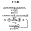
- step S124 the engine rotational speed Ne exceeds a cylinder cut-off lower rotational speed limit, or if the hydraulic pressure generated by the oil pump 13 exceeds a cylinder cut-off lower hydraulic pressure limit, then in step S125 the drive mode DriveMode is set at the electric creep mode EVCeep.
- step S131 the drive mode DriveMode is set at the deceleration mode Dec.
- step S141 the first clutch 14 is engaged, then in step S142 a cylinder cut-off solenoid is turned OFF so as to cancel the cylinder cut-off state of the engine E, a fuel injection permission INJ is turned ON, and an ignition permission IG is turned ON.
- step S143 the target ratio RatioObj of the belt type continuously variable transmission M is calculated from the accelerator pedal degree of opening AP and the vehicle speed Vcar, or from the required driving force F_REQ and the vehicle speed Vcar, and in step S144 a target engine rotational speed NeCmd is calculated from the target ratio RatioObj and the vehicle speed Vcar.
- step S145 shift processing is carried out so that the actual ratio Ratio of the belt type continuously variable transmission M coincides with the target ratio RatioObj, and in step S146 the front motor/generator MG1 is operated as a motor or a generator so that the engine rotational speed Ne coincides with the target engine rotational speed NeCmd.
- step S147 If in the subsequent step S147 the deviation
- a throttle valve should be opened by an amount corresponding to a no-load state of the engine E, which depends on the engine rotational speed Ne.
- the purpose of the throttle valve being opened by the amount corresponding to the no-load state is to make the output torque of the crankshaft 11 equal to 0, that is, the engine E is made to carry out work corresponding to its friction.
- the rear motor/generator MG2 is made to generate a driving force until the target ratio RatioObj and the target engine rotational speed NeCmd are achieved.
- step S154 the second clutch 20 is engaged (including the so-called half-clutch), and in step S155 the engine driving force command F_ENG is set at the required driving force F_REQ.
- step S156 the actual engine driving force F_ENG_ACT is calculated from the engine rotational speed-Ne and an intake negative pressure Pb (or an intake air volume), and in step S157 the rear motor/generator driving force command F_RrMot is set at the required driving force F_REQ - the actual engine driving force F_ENG_ACT.
- step S158 If in the subsequent step S158 the actual engine driving force F_ENG_ACT coincides with the required driving force F_REQ, that is, the rear motor/generator MG2 stops and only the engine E generates a driving force, then in step S159 the drive mode DriveMode is set at the engine mode ENG.
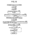
- step S161 the first clutch 14 is engaged, in step S162 the second clutch 20 is engaged, then in step S163 the cylinder cut-off solenoid is turned OFF so as to cancel the cylinder cut-off state of the engine E, the fuel injection permission INJ is turned ON, and the ignition permission IG is turned ON.
- step S164 the target ratio RatioObj of the belt type continuously variable transmission M is calculated from the accelerator pedal degree of opening AP and the vehicle speed Vcar, or the required driving force F_REQ and the vehicle speed Vcar, in step S165 shift processing is carried out so that the actual ratio Ratio of the belt type continuously variable transmission M coincides with the target ratio RatioObj, and in step S166 the engine driving force command F_REQ is set at 0 (no-load throttle degree of opening).
- the actual engine driving force F_ENG_ACT is calculated from the engine rotational speed Ne and the intake negative pressure Pb (or an intake air volume), and in step S168 the rear motor/generator driving force command F_RrMot is set at the required driving force F_REQ - the actual engine driving force F_ENG_ACT.
- the drive mode DriveMode is set at the electric mode EV.
- the oil pump 13 is driven by the front motor/generator MG1 in a state in which the pumping loss of the engine E is reduced by the pumping loss reduction means maintaining the intake valve of the engine E in a valve closed state and the second clutch 20 is disengaged.
- the engine E rotated by the front motor/generator MG1 is in a state in which the pumping loss is reduced, and the front motor/generator MG1 is disconnected from the front wheels Wf by the second clutch 20 being disengaged, it is possible to minimize the power consumption by reducing the load of the front motor/generator MG1. Furthermore, by disengaging the first clutch 14 when the front motor/generator MG1 is driven, it is possible to prevent drag on the belt type continuously variable transmission M, thus reducing the power consumption of the front motor/generator MG1.
- the engine E since the engine E is made to idle by the front motor/generator MG1, the engine E can be started rapidly by controlling the ignition and starting to supply fuel, and it is possible to smoothly and rapidly transfer from a state of traveling by means of the rear motor/generator MG2 to a state of traveling by means of the engine E.
- the belt type continuously variable transmission M is illustrated as the automatic transmission, but the present invention can also be applied to a continuously variable transmission other than the belt type continuously variable transmission or to-a stepped automatic transmission.
- a torque converter may be provided instead of the damper 12.
- the pumping loss reduction means is not limited to the embodiment, and may employ means in which both an intake valve and an exhaust valve are fully closed, or a throttle valve is fully opened.
- the drive mode of the vehicle V other than those described in the embodiment, there can be considered a mode in which the driving force of the engine E is assisted by one or both of the first and second motor/generators MG1 and MG2, or a mode in which, without using the engine E, the vehicle travels by means of the driving force of both of the first and second motor/generators MG1 and MG2.
Abstract
Description
- The present invention relates to a hybrid vehicle in which an engine equipped with pumping loss reduction means is connected to a first driven wheel via a first motor/generator, an oil pump, a first clutch, a hydraulic automatic transmission, and a second clutch, and a second motor/generator is connected to a second driven wheel.
- A hybrid vehicle in which a first motor/generator, an oil pump, a first clutch, a belt type continuously variable transmission, a second clutch, and a second motor/generator are disposed between an engine and a driven wheel is known from generic Japanese Patent Application Laid-open No. 2001-200920 (&EP111619A). This conventional hybrid vehicle starts off and accelerates by means of the driving force of the engine, and the driving force of the engine is assisted by making the first motor/generator function as a motor; during cruising, the engine is stopped, and the vehicle travels by making the second motor/generator function as a motor; and during deceleration, electrical energy is recovered by making the first and second motor/generators function as generators.
- When the engine is running, it is possible to generate a hydraulic pressure for shifting the belt type continuously variable transmission with the oil pump, which is driven by the engine, but when the engine is stopped and the vehicle travels by means of the driving force of the second motor/generator, since the oil pump generates no hydraulic pressure, when switching from traveling by means of the driving force of the second motor/generator to traveling by means of the driving force of the engine, there is a time lag until the oil pump generates a hydraulic pressure and shifting of the belt type continuously variable transmission becomes possible, and there is a possibility that the ratio control responsiveness might be degraded thus causing shift shock to occur.
- In the above-mentioned conventional arrangement, in addition to the oil pump driven by the engine, an electric oil pump is provided, and by generating a hydraulic pressure with the electric hydraulic pump when the engine is stopped, the actual ratio of the belt type continuously variable transmission is rapidly made to coincide with a target ratio when switching over from traveling by means of the driving force of the second motor/generator to traveling by means of the driving force of the engine.
- However, in the above-mentioned conventional arrangement, since it is necessary to employ an electric oil pump in addition to the oil pump driven by the engine, there is the problem that the number of components, cost, space, weight, etc. are increased by an amount corresponding to the electric oil pump and a motor for driving it.
- The present invention has been accomplished under the above-mentioned circumstances, and it is an object thereof to provide a hybrid vehicle that can travel by means of a motor/generator while an engine is stopped, and that enables hydraulic pressure for shifting an automatic transmission to be generated when the engine is stopped, without requiring a special electric oil pump.
- In order to attain this object, in accordance with a first aspect of the present invention, there is proposed a hybrid vehicle in which an engine equipped with pumping loss reduction means is connected to a first driven wheel via a first motor/generator, an oil pump, a first clutch, a hydraulic automatic transmission, and a second clutch, and a second motor/generator is connected to a second driven wheel, the second driven wheel being different from the first driven wheel, characterized in that when the vehicle is made to travel by driving or braking the second driven wheel with the second motor/generator, in order to shift the automatic transmission a hydraulic pressure is generated by driving the oil pump with the first motor/generator in a state in which the pumping loss of the engine, which has stopped running, is reduced by the pumping loss reduction means and the second clutch is disengaged.
- In accordance with this arrangement, when the vehicle is made to travel by driving or braking the second driven wheel with the second motor/generator while operation of the engine is stopped, since the oil pump is driven by the first motor/generator while the pumping loss of the engine is reduced by the pumping loss reduction means and the second clutch is disengaged, not only is it possible to shift the automatic transmission with the hydraulic pressure generated by the existing oil pump without providing a special electric oil pump, but it is also possible to prevent shift shock from occurring by controlling the actual ratio of the automatic transmission at a target ratio with good responsiveness when the engine is started and the first driven wheel is driven via the automatic transmission. Moreover, since the engine rotated by the first motor/generator is in a state in which the pumping loss is reduced, and the first motor/generator is disconnected from the first driven wheel by the second clutch being disengaged, not only is it possible to minimize the power consumption of the first motor/generator, but it is also possible to start the engine rapidly by controlling the ignition and starting the supply of fuel.
- Furthermore, in accordance with a second aspect of the present invention, in addition to the first aspect, there is proposed the hybrid vehicle wherein, when a deviation of the actual ratio of the automatic transmission from a target ratio exceeds a predetermined value, the automatic transmission is shifted while intermittently engaging the first clutch.
- In accordance with this arrangement, since the automatic transmission is shifted by engaging the first clutch when the deviation of the actual ratio from the target ratio exceeds the predetermined value, compared with a case in which shifting is carried out by continuously engaging the first clutch it is possible to reduce the power consumption by minimizing the time for which the automatic transmission is driven by the first motor/generator.
- Moreover, in accordance with a third aspect of the present invention, in addition to the first aspect, there is proposed the hybrid vehicle wherein, when the percentage change of a target ratio of the automatic transmission exceeds a predetermined value, the automatic transmission is shifted while continuously engaging the first clutch.
- In accordance with this arrangement, since the automatic transmission is shifted while continuously engaging the first clutch when the percentage change of the target ratio of the automatic transmission exceeds the predetermined value, shifting can be carried out without delay when rapid shifting is necessary.
- Furthermore, in accordance with a fourth aspect of the present invention, in addition to the first aspect, there is proposed the hybrid vehicle wherein, when the remaining capacity of a battery connected to the first and second motor/generators exceeds a predetermined value, the required driving force of the vehicle is less than a predetermined value, and the pumping loss of the engine can be reduced, traveling by means of the second motor/generator is permitted.
- In accordance with this arrangement, since traveling by means of the second motor/generator is permitted when the remaining capacity of the battery is sufficient, the remaining capacity of the battery does not become insufficient; since traveling by means of the second motor/generator is permitted when the required driving force of the vehicle is small, the driving force of the vehicle does not become insufficient; and since traveling by means of the second motor/generator is permitted when the pumping loss of the engine can be reduced, it is possible to minimize the power consumption of the first motor/generator for driving the oil pump and the engine.
- Moreover, in accordance with a fifth aspect of the present invention, in addition to the fourth aspect, there is proposed the hybrid vehicle wherein, when the pumping loss reduction means is operated and traveling is carried out by means of the second motor/generator, a hydraulic pressure for shifting the automatic transmission is generated by driving the oil pump with the first motor/generator.
- In accordance with this arrangement, since the hydraulic pressure for shifting the automatic transmission is generated by driving the oil pump with the first motor/generator when traveling is carried out by means of the second motor/generator in a state in which the pumping loss of the engine is reduced, it is possible to rapidly shift the automatic transmission in readiness for traveling by means of the engine while minimizing the power consumption of the first motor/generator.
- Furthermore, in accordance with a sixth aspect of the present invention, in addition to the first aspect, there is proposed the hybrid vehicle wherein, when a hydraulic pressure is generated in order to shift the automatic transmission by driving the oil pump with the first motor/generator, the first clutch is disengaged.
- In accordance with this arrangement, since the first clutch is disengaged when the oil pump is driven by the first motor/generator, it is possible to prevent drag on the automatic transmission from the driving force of the first motor/generator, thus reducing the power consumption.
- A belt type continuously variable transmission M of an embodiment corresponds to the automatic transmission of the present invention, a front motor/generator MG1 and a rear motor/generator MG2 of the embodiment correspond to the first motor/generator and the second motor/generator respectively of the present invention, and front wheels Wf and rear wheels Wr of the embodiment correspond to the first driven wheel and the second driven wheel of the present invention.
-
- FIG. 1 to FIG. 13 illustrate one embodiment of the present invention; FIG. 1 is a diagram of the overall arrangement of a power transmission system of a hybrid vehicle, FIG. 2 is a flow chart of a drive mode determination routine, FIG. 3 is a flow chart of a mode transition processing routine, FIG. 4 is a flow chart of a stop mode processing routine, FIG. 5 is a flow chart of an electric creep mode processing routine, FIG. 6 is a flow chart of a deceleration mode processing routine, FIG. 7 is a flow chart of an engine mode processing routine, FIG. 8 is a flow chart of an electric mode processing routine, FIG. 9 is a flow chart of a stop mode transition processing routine, FIG. 10 is a flow chart of an electric creep mode transition processing routine, FIG. 11 is a flow chart of a deceleration mode transition processing routine, FIG. 12 is a flow chart of an engine mode transition processing routine, and FIG. 13 is a flow chart of an electric mode transition processing routine.
- An embodiment of the present invention is explained below with reference to the attached drawings.
- As shown in FIG. 1, connected in series to a
crankshaft 11 of an engine E that can put all cylinders in a cut-off state are a front motor/generator MG1, adamper 12, anoil pump 13, afirst clutch 14, and aninput shaft 15 of a belt type continuously variable transmission M. Anendless belt 19 is wound around adrive pulley 16 provided on theinput shaft 15 and a drivenpulley 18 provided on atransmission output shaft 17. Thedamper 12 has the functions of suppressing torque shock when a sudden torque is transmitted from the engine E and suppressing the amplitude of torsional vibration of thecrankshaft 11. Thetransmission output shaft 17 is connected to left and right front wheels Wf via asecond clutch 20, afinal drive gear 21, a final drivengear 22, a frontdifferential gear 23, and left andright axles 24. A rear motor/generator MG2 is connected to left and right rear wheels Wr via a reardifferential gear 25 and left andright axles 26. - The front and rear motor/generators MG1 and MG2 are connected to a
battery 28 via apower drive unit 27. - During normal operation, an intake valve of the engine E is controlled so as to open and close in association with rotation of the crankshaft, but when running with the cylinders in a cut-off state, in order to reduce the pumping loss of the engine E, the intake valve is kept closed by pumping loss reduction means. Therefore, when the
crankshaft 11 of the engine E is rotated by the front motor/generator MG1 while the cylinders of the engine E are in a cut-off state, the driving load can be minimized. - Although not specifically illustrated in this embodiment, the engine E, the belt type continuously variable transmission M, the front motor/generator MG1, the rear motor/generator MG2, and the
battery 28 are controlled by corresponding ECUs (electronic control units), and there is also provided an integrating ECU for integrating these ECUs. Control in the flow charts of FIG. 2 to FIG. 13 described below is carried out by the integrating ECU. - With regard to the drive mode of a hybrid vehicle, there are five modes, that is, a 'stop mode', an 'electric creep mode', a 'deceleration mode', an 'engine mode', and an 'electric mode', and the mode is determined by the flow chart of a drive mode determination routine of FIG. 2.
- That is, if in step S1 a vehicle speed Vcar is 0 and a brake switch Brk is ON, then in step S2 it is determined that a requested drive mode DriveModeReq is the 'stop mode'.
- When the answer in step S1 is NO, then if in step S3 an accelerator pedal degree of opening AP is fully closed, the brake switch Brk is OFF, the vehicle speed Vcar is less than a creep determination vehicle speed V_Crp, and a remaining battery capacity SOC exceeds a permitted electric travel remaining capacity SOC_EV, then in step S4 it is determined that the requested drive mode DriveModeReq is the 'electric creep mode'. The 'electric creep mode' is a travel mode in which the vehicle is made to creep by means of the driving force of the second motor/generator MG2.
- When the answer in step S3 is NO, then if in step S5 the accelerator pedal degree of opening AP is fully closed and the vehicle speed Vcar exceeds the creep determination vehicle speed V_Crp, or if in step S6 the accelerator pedal degree of opening AP is fully closed, the brake switch Brk is ON, and the vehicle speed Vcar is not 0, then in step S7 it is determined that the requested drive mode DriveModeReq is the 'deceleration mode'.
- When the answers in steps S5 and S6 are both NO, if in step S8 a required driving force F_REQ is not less than a permitted electric travel driving force F_EV, or if in step S9 the remaining battery capacity SOC does not exceed the permitted electric travel remaining capacity SOC_EV, or if in step S10 a cylinder cut-off permission flag KYUTOENB is not equal to 1 (cylinder cut-off permission), then in step S11 it is determined that the requested drive mode DriveModeReq is the 'engine mode'. If the answers in steps S8 to S10 are all YES, then in step S12 it is determined that the requested drive mode DriveModeReq is the 'electric mode'. The 'electric mode' is a mode in which the vehicle is made to travel by the driving force of the second motor/generator MG2.
- Since traveling by means of the second motor/generator MG2 is permitted when the required driving force F_REQ is small in step S8, the driving force for the vehicle does not become insufficient. Since traveling by means of the second motor/generator MG2 is also permitted when the remaining capacity of the
battery 28 is sufficient in step S9, the capacity of thebattery 28 does not become insufficient. Since traveling by means of the second motor/generator MG2 is also permitted when the engine E can be in a cylinder cut-off state in step S10, it is possible to minimize the power consumption of the first motor/generator MG1, which rotates the engine E in a cylinder cut-off state together with theoil pump 13. - A mode transition processing routine is now explained with reference to the flow chart of FIG. 3.
- Firstly, in step S21, when a current drive mode DriveMode coincides with the requested drive mode DriveModeReq, then if in step S22 the drive mode DriveMode is the 'stop mode', then in step S23 stop mode processing is carried out, if in step S24 the drive mode DriveMode is the 'electric creep mode', then in step S25 electric creep mode processing is carried out, if in step S26 the drive mode DriveMode is the 'deceleration mode', then in step S27 deceleration mode processing is carried out, if in step S28 the drive mode DriveMode is the 'engine mode', then in step S29 engine mode processing is carried out, and if in step S30 the drive mode DriveMode is the 'electric mode', then in step S31 electric mode processing is carried out.
- On the other hand, when the current drive mode DriveMode does not coincide with the requested drive mode DriveModeReq in step S21, if in step S32 the requested drive mode DriveModeReq is the 'stop mode', then in step S33 stop mode transition processing is carried out, if in step S34 the requested drive mode DriveModeReq is the 'electric creep mode', then in step S35 electric creep mode transition processing is carried out, if in step S36 the requested drive mode DriveModeReq is the 'deceleration mode', then in step S37 deceleration mode transition processing is carried out, if in step S38 the requested drive mode DriveModeReq is the 'engine mode', then in step S39 engine mode transition processing is carried out, and if in step S40 the requested drive mode DriveModeReq is the 'electric mode', then in step S41 electric mode transition processing is carried out.
- A subroutine of the 'stop mode processing' of step S23 of the flow chart of FIG. 3 is now explained with reference to the flow chart of FIG. 4.
- Firstly, in step S51 the
first clutch 14 is disengaged, and in step S52 thesecond clutch 20 is disengaged. In the subsequent step S53, when the remaining battery capacity SOC is not greater than a permitted idle stop capacity SOC_IS (the remaining capacity that enables the engine E to be restarted even if it is put in an idle stop state), that is, when the remaining battery capacity SOC is insufficient, if in step S54 the engine E is firing fully, then in step S55 in order to carry out charging with the front motor/generator MG1, a front motor/generator drive command F_FrMot is set at an idle charge command F_IdIChg (negative value), and in step S56 an engine drive command F_ENG is set at the idle charge command F_IdIChg (positive value). By so doing, while running the engine E the front motor/generator MG1 is made to function as a generator, thus charging thebattery 28. - In step S54, if the engine E is not firing fully, in step S57 the front motor/generator MG1 is made to function as a motor so as to crank the engine E, and in step S58 the engine drive command F_ENG is set at 0 (no load throttle degree of opening), thus starting the engine E.
- A subroutine of the 'electric creep mode processing' of step S25 of the flow chart of FIG. 3 is now explained with reference to the flow chart of FIG. 5.
- Firstly, in step S71 the
second clutch 20 is disengaged, and in step S72 driving the front motor/generator MG1 as a motor and idling the engine E in a cylinder cut-off state allows theoil pump 13 to be driven while minimizing the pumping loss of the engine E, thus generating a hydraulic pressure for shifting the belt type continuously variable transmission M. In the subsequent step S73, the driving force command for the rear motor/generator MG2 is set at a required driving force F_REQ, and the rear motor/generator MG2 is made to function as a motor, thus making the vehicle creep electrically. - In the subsequent step S74, a target ratio RatioObj of the belt type continuously variable transmission M is calculated from the accelerator pedal degree of opening AP and the vehicle speed Vcar, or the required driving force F_REQ and the vehicle speed Vcar. In step S75, when a percentage target ratio change |ΔRatioObj| exceeds a predetermined value, that is, the percentage target ratio change |ΔRatioObj| is large, then in step S76 the
first clutch 14 is engaged, and in step S77 shift processing is carried out so that the actual ratio Ratio of the belt type continuously variable transmission M coincides with the target ratio RatioObj. The hydraulic pressure required in this process employs a hydraulic pressure that is generated by theoil pump 13 by driving the engine E in the cylinder cut-off state with the front motor/generator MG1. In step S78, a ratio check timer TmRatioChk (down count timer) is set at a predetermined time TRATIOCHK. - As a result of the shift processing being carried out in step S77, in step S75 even if the percentage target ratio change |ΔRatioObj| does not exceed the predetermined value, if in the subsequent step S79 the ratio check timer TmRatioChk has timed up, then in step S80 the
first clutch 14 is engaged. If in step S81 a deviation |RatioObj - Ratio| of the actual ratio Ratio from the target ratio RatioObj is not less than a predetermined value, that is, the deviation |RatioObj - Ratio| is large, then in step S82 shift processing is carried out so that the actual ratio Ratio of the belt type continuously variable transmission M coincides with the target ratio RatioObj. The hydraulic pressure required in this process employs a hydraulic pressure that is generated by theoil pump 13 by driving the engine E in the cylinder cut-off state with the front motor/generator MG1. On the other hand, if in step S81 the deviation |RatioObj - Ratio| is less than the predetermined value, then in step S78 the ratio check timer TmRatioChk is set at the predetermined time TRATIOCHK. If in the step S79 the ratio check timer TmRatioChk has not timed up, then in step S83 the first clutch 14 is disengaged. - In this way, if the percentage target ratio change |ΔRatioObj| exceeds the predetermined value when the engine E is in the cylinder cut-off state, then the first clutch 14 is engaged so as to drive the
oil pump 13, the actual ratio Ratio of the belt type continuously variable transmission M is controlled at the target ratio RatioObj by the hydraulic pressure generated by theoil pump 13, each time the predetermined time TRATIOCHK elapses the first clutch 14 is engaged to drive theoil pump 13, and in this process if the deviation |RatioObj - Ratio| of the actual ratio Ratio from the target ratio RatioObj is not less than the predetermined value, then the actual ratio Ratio of the belt type continuously variable transmission M is controlled at the target ratio RatioObj, thereby enabling delay in response of shifting of the belt type continuously variable transmission M to be prevented. - A subroutine of the 'deceleration mode processing' of step S27 of the flow chart of FIG. 3 is now explained with reference to the flow chart of FIG. 6.
- The flow chart of FIG. 6 is substantially the same as that of FIG. 5; when the vehicle is decelerated, in the same manner as when the vehicle is made to creep electrically, the first clutch 14 is engaged under predetermined conditions so as to rotate the
drive pulley 16 and the drivenpulley 18 of the belt type continuously variable transmission M, and shifting to the target ratio RatioObj is carried out while checking the actual ratio Ratio; it is therefore possible to reliably prevent a delay in response of shifting of the belt type continuously variable transmission M. The only difference is that, in step S73 of the flow chart of FIG. 5 the rear motor/generator driving force command F_RrMot is set at the required driving force F_REQ, and the rear motor/generator MG2 is made to function as a motor so as to make the vehicle creep electrically, but in step S73' of the flow chart of FIG. 6 the rear motor/generator driving force command F_RrMot is set at the required driving force F_REQ (regenerative braking), and the rear motor/generator MG2 is made to function as a generator so as to generate a regenerative braking force, thus recovering the kinetic energy of the vehicle as electrical energy in thebattery 28. - A subroutine of the 'engine mode processing' of step S29 of the flow chart of FIG. 3 is now explained with reference to the flow chart of FIG. 7.
- Firstly, in step S91 the first clutch 14 is engaged (including the so-called half-clutch control), in step S92 the second clutch 20 is engaged, and in step S93 the target ratio RatioObj of the belt type continuously variable transmission M is calculated from the accelerator pedal degree of opening AP and the vehicle speed Vcar, or from the required driving force F_REQ and the vehicle speed Vcar. In step S94, shift processing is carried out so that the actual ratio Ratio of the belt type continuously variable transmission M coincides with the target ratio RatioObj.
- In the subsequent step S95, if the mode is an assist mode, then in step S96 the front motor/generator driving force command F_FrMot is set at the front required assist driving force F_AstFrMot, the rear motor/generator driving force command F_RrMot is set at the rear required assist driving force F_AstRrMot, and the front motor/generator MG1 and the rear motor/generator MG2 are driven as motors, thus assisting the driving force of the engine E. In step S97, if the mode is a charging mode, in step S98 the front motor/generator driving force command F_FrMot is set at a charging driving force F_Chg, the rear motor/generator driving force command F_RrMot is set at 0, and the front motor/generator MG1 is driven as a generator, thus charging the
battery 28. In steps S95 and S97, if the mode is neither the assist mode or the charging mode, in step S99 both the front motor/generator driving force command F_FrMot and the rear motor/generator driving force command F_RrMot are set at 0, thus running only the engine E. - In step S100, the driving force command F_ENG of the engine E is calculated by subtracting, from the required driving force F_REQ, the front motor/generator driving force command F_FrMot and the rear motor/generator driving force command F_RrMot. That is, the total required driving force of the engine E, the front motor/generator MG1, and the rear motor/generator MG2 is made to coincide with the required driving force F_REQ.
- A subroutine of the 'electric mode processing' of step S31 of the flow chart of FIG. 3 is now explained with reference to the flow chart of FIG. 8.
- The flow chart of FIG. 8 is substantially the same as that of FIG. 5; when the vehicle travels electrically, in the same manner as when the vehicle creeps electrically, the first clutch 14 is engaged under predetermined conditions so as to rotate the
drive pulley 16 and the drivenpulley 18 of the belt type continuously variable transmission M, and shifting to the target ratio RatioObj is carried out while checking the actual ratio Ratio; it is therefore possible to reliably prevent a delay in response of shifting of the belt type continuously variable transmission M. The only difference is that, in step S73 of the flow chart of FIG. 5 the required driving force F_REQ of the rear motor/generator MG2 is a small value for electric creep traveling, but in step S73" of the flow chart of FIG. 8, the required driving force F_REQ of the rear motor/generator MG2 is a large value for electrical traveling. - The subroutine of the 'stop mode transition processing' of step S33 of the flow chart of FIG. 3 is explained with reference to the flow chart of FIG. 9.
- Firstly, in step S111 the first clutch 14 is engaged, in step S112 the second clutch 20 is disengaged, and in step S113 the target ratio RatioObj of the belt type continuously variable transmission M is calculated from the accelerator pedal degree of opening AP and the vehicle speed Vcar, or the required driving force F_REQ and the vehicle speed Vcar. If in step S114 the deviation |RatioObj - Ratio| of the actual ratio Ratio from the target ratio RatioObj is not less than a predetermined value, that is, the deviation |RatioObj - Ratio| is large, then in step S115 shift processing is carried out so that the actual ratio Ratio of the belt type continuously variable transmission M coincides with the target ratio RatioObj. On the other hand, if in step S114 the deviation |RatioObj - Ratio| is less than the predetermined value, then the drive mode DriveMode is set at the stop mode Stop. In this way, in a state in which the second clutch 20 is disengaged and the first clutch 14 is engaged, after the actual ratio Ratio of the belt type continuously variable transmission M is made to coincide with the target ratio RatioObj, a transition to the 'stop mode' is carried out.
- A subroutine of the 'electric creep mode transition processing' of step S35 of the flow chart of FIG. 3 is explained with reference to the flow chart of FIG. 10.
- Firstly, in step S121 the first clutch 14 is disengaged, in step S112 the second clutch 20 is disengaged, and in step S123 the front motor/generator MG1 is driven as a motor so as to make the engine E idle in a cylinder cut-off state, thereby generating a hydraulic pressure for shifting the belt type continuously variable transmission M by driving the
oil pump 13 while minimizing the pumping loss of the engine E. If in the subsequent step S124 the engine rotational speed Ne exceeds a cylinder cut-off lower rotational speed limit, or if the hydraulic pressure generated by theoil pump 13 exceeds a cylinder cut-off lower hydraulic pressure limit, then in step S125 the drive mode DriveMode is set at the electric creep mode EVCeep. - A subroutine of the 'deceleration mode transition processing' of step S37 of the flow chart of FIG. 3 is explained with reference to the flow chart of FIG. 11.
- In step S131 the drive mode DriveMode is set at the deceleration mode Dec.
- A subroutine of the 'engine mode transition processing' of step S39 of the flow chart of FIG. 3 is explained with reference to the flow chart of FIG. 12.
- Firstly in step S141 the first clutch 14 is engaged, then in step S142 a cylinder cut-off solenoid is turned OFF so as to cancel the cylinder cut-off state of the engine E, a fuel injection permission INJ is turned ON, and an ignition permission IG is turned ON. In the subsequent step S143, the target ratio RatioObj of the belt type continuously variable transmission M is calculated from the accelerator pedal degree of opening AP and the vehicle speed Vcar, or from the required driving force F_REQ and the vehicle speed Vcar, and in step S144 a target engine rotational speed NeCmd is calculated from the target ratio RatioObj and the vehicle speed Vcar. Subsequently, in step S145 shift processing is carried out so that the actual ratio Ratio of the belt type continuously variable transmission M coincides with the target ratio RatioObj, and in step S146 the front motor/generator MG1 is operated as a motor or a generator so that the engine rotational speed Ne coincides with the target engine rotational speed NeCmd.
- If in the subsequent step S147 the deviation |RatioObj - Ratio| of the actual ratio Ratio from the target ratio RatioObj is not less than a predetermined value, that is, if the deviation |RatioObj - Ratio| is large, or if in step S148 the percentage target ratio change |ΔRatioObj| is not less than a predetermined value, that is, the percentage target ratio change |ΔRatioObj| is large, or if in step S149 the engine E is not firing fully, or if in step S150 if the deviation |NeCmd - Ne| of the engine rotational speed Ne from the target engine rotational speed NeCmd is not less than a predetermined value, that is, the deviation |NeCmd - Nel is large, then in step S151 the second clutch 20 is disengaged, in step S152 the rear motor/generator driving force command F_RrMot is set at the required driving force F_REQ, and in step S153 the engine driving force command F_ENG is set at 0.
- Here, a throttle valve should be opened by an amount corresponding to a no-load state of the engine E, which depends on the engine rotational speed Ne. The purpose of the throttle valve being opened by the amount corresponding to the no-load state is to make the output torque of the
crankshaft 11 equal to 0, that is, the engine E is made to carry out work corresponding to its friction. In this way, the rear motor/generator MG2 is made to generate a driving force until the target ratio RatioObj and the target engine rotational speed NeCmd are achieved. - If the answers in steps S147 to S150 are all YES, that is, if traveling by means of the engine E is possible, then in step S154 the second clutch 20 is engaged (including the so-called half-clutch), and in step S155 the engine driving force command F_ENG is set at the required driving force F_REQ. In the subsequent step S156 the actual engine driving force F_ENG_ACT is calculated from the engine rotational speed-Ne and an intake negative pressure Pb (or an intake air volume), and in step S157 the rear motor/generator driving force command F_RrMot is set at the required driving force F_REQ - the actual engine driving force F_ENG_ACT. If in the subsequent step S158 the actual engine driving force F_ENG_ACT coincides with the required driving force F_REQ, that is, the rear motor/generator MG2 stops and only the engine E generates a driving force, then in step S159 the drive mode DriveMode is set at the engine mode ENG.
- A subroutine of the 'electric mode transition processing' of step S41 of the flow chart of FIG. 3 is now explained with reference to the flow chart of FIG. 13.
- Firstly in step S161 the first clutch 14 is engaged, in step S162 the second clutch 20 is engaged, then in step S163 the cylinder cut-off solenoid is turned OFF so as to cancel the cylinder cut-off state of the engine E, the fuel injection permission INJ is turned ON, and the ignition permission IG is turned ON. In the subsequent step S164, the target ratio RatioObj of the belt type continuously variable transmission M is calculated from the accelerator pedal degree of opening AP and the vehicle speed Vcar, or the required driving force F_REQ and the vehicle speed Vcar, in step S165 shift processing is carried out so that the actual ratio Ratio of the belt type continuously variable transmission M coincides with the target ratio RatioObj, and in step S166 the engine driving force command F_REQ is set at 0 (no-load throttle degree of opening).
- In the subsequent step S167, the actual engine driving force F_ENG_ACT is calculated from the engine rotational speed Ne and the intake negative pressure Pb (or an intake air volume), and in step S168 the rear motor/generator driving force command F_RrMot is set at the required driving force F_REQ - the actual engine driving force F_ENG_ACT. In the subsequent step S169 if the actual engine driving force F_ENG_ACT is 0, that is, the rear motor/generator MG2 generates all of the required driving force F_REQ, then in step S170 the drive mode DriveMode is set at the electric mode EV.
- As hereinbefore described, in accordance with the present embodiment, when the vehicle travels while the operation of the engine E is stopped and the rear wheels Wr are driven or braked by the rear motor/generator MG2, that is, in the 'electric creep mode' of FIG. 5, the 'deceleration mode' of FIG. 6, and the 'electric mode' of FIG. 8, the
oil pump 13 is driven by the front motor/generator MG1 in a state in which the pumping loss of the engine E is reduced by the pumping loss reduction means maintaining the intake valve of the engine E in a valve closed state and the second clutch 20 is disengaged. It is therefore possible to shift the belt type continuously variable transmission M by means of the hydraulic pressure generated by theoil pump 13 even when the engine E is stopped, and it is possible to prevent shift shock from occurring by controlling the actual ratio of the belt type continuously variable transmission M at a target ratio with good responsiveness when the engine is started and the front wheels Wf are driven via the belt type continuously variable transmission M. - Here, since the engine E rotated by the front motor/generator MG1 is in a state in which the pumping loss is reduced, and the front motor/generator MG1 is disconnected from the front wheels Wf by the second clutch 20 being disengaged, it is possible to minimize the power consumption by reducing the load of the front motor/generator MG1. Furthermore, by disengaging the first clutch 14 when the front motor/generator MG1 is driven, it is possible to prevent drag on the belt type continuously variable transmission M, thus reducing the power consumption of the front motor/generator MG1. Moreover, since the engine E is made to idle by the front motor/generator MG1, the engine E can be started rapidly by controlling the ignition and starting to supply fuel, and it is possible to smoothly and rapidly transfer from a state of traveling by means of the rear motor/generator MG2 to a state of traveling by means of the engine E.
- Furthermore, when the vehicle travels by means of the rear motor/generator MG2 while the engine E is stopped, since the belt type continuously variable transmission M is shifted by intermittently engaging the first clutch 14 when the deviation |RatioObj - Ratio| of the actual ratio from the target ratio of the belt type continuously variable transmission M exceeds a predetermined value, compared with a case in which shifting is carried out by continuously engaging the first clutch 14 while the engine E is stopped, it is possible to reduce the power consumption by minimizing the time for which the belt type continuously variable transmission M is driven by the front motor/generator MG1. Moreover, since shifting is carried out by continuously engaging the first clutch 14 when the percentage target ratio change |ΔRatioObj| of the belt type continuously variable transmission M exceeds a predetermined value, when it is necessary to rapidly shift the belt type continuously variable transmission M, it can be shifted without delay.
- Although an embodiment of the present invention is explained above, the present invention can be modified in a variety of ways without departing from the scope and spirit thereof.
- For example, in the embodiment, the belt type continuously variable transmission M is illustrated as the automatic transmission, but the present invention can also be applied to a continuously variable transmission other than the belt type continuously variable transmission or to-a stepped automatic transmission.
- Furthermore, instead of the
damper 12, a torque converter may be provided. - Moreover, the pumping loss reduction means is not limited to the embodiment, and may employ means in which both an intake valve and an exhaust valve are fully closed, or a throttle valve is fully opened.
- Furthermore, with regard to the drive mode of the vehicle V, other than those described in the embodiment, there can be considered a mode in which the driving force of the engine E is assisted by one or both of the first and second motor/generators MG1 and MG2, or a mode in which, without using the engine E, the vehicle travels by means of the driving force of both of the first and second motor/generators MG1 and MG2.
Claims (6)
- A hybrid vehicle in which an engine (E) equipped with pumping loss reduction means is connected to a first driven wheel via a first motor/generator (MG1), an oil pump (13), a first clutch (14), a hydraulic automatic transmission (M), and a second clutch (20), and a second motor/generator (MG2) is connected to a second driven wheel (Wr), the second driven wheel (Wr) being different from the first driven wheel (Wf), characterized in that when the vehicle is made to travel by driving or braking the second driven wheel (Wr) with the second motor/generator (MG2), in order to shift the automatic transmission (M) a hydraulic pressure is generated by driving the oil pump (13) with the first motor/generator (MG1) in a state in which the pumping loss of the engine (E), which has stopped running, is reduced by the pumping loss reduction means and the second clutch (20) is disengaged.
- The hybrid vehicle according to Claim 1 wherein, when a deviation of the actual ratio of the automatic transmission (M) from a target ratio exceeds a predetermined value, the automatic transmission (M) is shifted while intermittently engaging the first clutch (14).
- The hybrid vehicle according to Claim 1 wherein, when the percentage change of a target ratio of the automatic transmission (M) exceeds a predetermined value, the automatic transmission (M) is shifted while continuously engaging the first clutch (14).
- The hybrid vehicle according to Claim 1 wherein, when the remaining capacity of a battery (28) connected to the first and second motor/generators (MG1, MG2) exceeds a predetermined value, the required driving force of the vehicle is less than a predetermined value, and the pumping loss of the engine (E) can be reduced, traveling by means of the second motor/generator (MG2) is permitted.
- The hybrid vehicle according to Claim 4 wherein, when the pumping loss reduction means is operated and traveling is carried out by means of the second motor/generator (MG2), a hydraulic pressure for shifting the automatic transmission (M) is generated by driving the oil pump (13) with the first motor/generator (MG1).
- The hybrid vehicle according to Claim 1 wherein, when a hydraulic pressure is generated in order to shift the automatic transmission (M) by driving the oil pump (13) with the first motor/generator (MG1), the first clutch (14) is disengaged.
Applications Claiming Priority (3)
| Application Number | Priority Date | Filing Date | Title |
|---|---|---|---|
| JP2002268400 | 2002-09-13 | ||
| JP2002268400 | 2002-09-13 | ||
| PCT/JP2003/008892 WO2004024486A1 (en) | 2002-09-13 | 2003-07-14 | Hybrid vehicle |
Publications (3)
| Publication Number | Publication Date |
|---|---|
| EP1541400A1 EP1541400A1 (en) | 2005-06-15 |
| EP1541400A4 EP1541400A4 (en) | 2005-12-14 |
| EP1541400B1 true EP1541400B1 (en) | 2006-08-16 |
Family
ID=31986762
Family Applications (1)
| Application Number | Title | Priority Date | Filing Date |
|---|---|---|---|
| EP03795201A Expired - Fee Related EP1541400B1 (en) | 2002-09-13 | 2003-07-14 | Hybrid vehicle |
Country Status (6)
| Country | Link |
|---|---|
| US (1) | US7490685B2 (en) |
| EP (1) | EP1541400B1 (en) |
| CN (1) | CN1301200C (en) |
| AU (1) | AU2003248064A1 (en) |
| DE (1) | DE60307657T8 (en) |
| WO (1) | WO2004024486A1 (en) |
Families Citing this family (50)
| Publication number | Priority date | Publication date | Assignee | Title |
|---|---|---|---|---|
| JP2006141077A (en) * | 2004-11-10 | 2006-06-01 | Hitachi Ltd | Drive device for vehicle |
| US20070095587A1 (en) * | 2005-11-03 | 2007-05-03 | Hybrid Dynamics Corp. | Hybrid vehicle drive train and method |
| US8050831B2 (en) * | 2006-04-07 | 2011-11-01 | Ford Global Technologies, Llc | Vehicle engine speed control for a continuously variable transmission |
| DE102006021156A1 (en) * | 2006-05-06 | 2007-11-08 | Lohner, Andreas, Prof.Dr.-Ing. | Hybrid drive topology e.g., diesel engine of personal vehicle, has rotor of electric machine converter unit with rotor connected via differential to driving vehicle axel |
| CN100406289C (en) * | 2006-06-08 | 2008-07-30 | 上海交通大学 | Series-parallel mixed power system |
| DE202006019422U1 (en) * | 2006-11-06 | 2008-04-10 | Faun Umwelttechnik Gmbh & Co. Kg | hybrid drive |
| CN101535075A (en) * | 2006-12-08 | 2009-09-16 | 比亚迪股份有限公司 | Hybrid power output system |
| CN101209667A (en) * | 2006-12-25 | 2008-07-02 | 比亚迪股份有限公司 | Mixed power outputting device |
| US8596390B2 (en) * | 2007-12-05 | 2013-12-03 | Ford Global Technologies, Llc | Torque control for hybrid electric vehicle speed control operation |
| US7988593B2 (en) * | 2008-02-11 | 2011-08-02 | Caterpillar Inc. | Creep control for motor system |
| JP5187834B2 (en) * | 2008-03-17 | 2013-04-24 | 現代自動車株式会社 | Clutch transmission torque control device for hybrid vehicle |
| US8042632B2 (en) * | 2008-10-15 | 2011-10-25 | GM Global Technology Operations LLC | Creep mode propulsion for stop-start hybrid vehicles |
| DE102008044272A1 (en) | 2008-12-02 | 2010-06-17 | Zf Friedrichshafen Ag | A method of operating a vehicle hybrid powertrain with an internal combustion engine and with an electric machine |
| US8473172B2 (en) * | 2009-01-02 | 2013-06-25 | Ford Global Technologies, Llc | System and methods for assisted direct start control |
| US9002600B2 (en) * | 2009-01-02 | 2015-04-07 | Ford Global Technologies, Llc | Methods and systems for engine shut-down control |
| US9764726B2 (en) | 2009-01-02 | 2017-09-19 | Ford Global Technologies, Llc | Methods and systems for assisted direct start control |
| TW201116426A (en) * | 2009-07-30 | 2011-05-16 | Hybrid Kinetic Motors Corp | Multi-fuel and electric-drive hybrid power train and vehicle using the same |
| US20110061954A1 (en) * | 2009-09-11 | 2011-03-17 | Gm Global Technology Operations, Inc. | Strong hybrid system |
| WO2011111199A1 (en) * | 2010-03-10 | 2011-09-15 | トヨタ自動車株式会社 | Hybrid drive device for vehicle |
| JP5471829B2 (en) * | 2010-05-25 | 2014-04-16 | 日産自動車株式会社 | Accelerator pedal force control device for hybrid vehicle |
| CN102310760A (en) * | 2010-06-30 | 2012-01-11 | 比亚迪股份有限公司 | Driving method of hybrid driving system |
| DE112012002583T5 (en) * | 2011-06-23 | 2014-03-20 | Honda Motor Co., Ltd. | Drive system and method for controlling the drive system |
| CN102358180A (en) * | 2011-09-02 | 2012-02-22 | 中国嘉陵工业股份有限公司(集团) | Power transmission device for light-duty all-terrain 4*4 vehicle |
| CA2847670A1 (en) * | 2011-09-05 | 2013-03-14 | Honda Motor Co., Ltd. | Control system and control method for hybrid vehicle |
| JP2013056629A (en) * | 2011-09-08 | 2013-03-28 | Kanzaki Kokyukoki Manufacturing Co Ltd | Hybrid drive system for working vehicle |
| US8682550B2 (en) | 2011-10-14 | 2014-03-25 | Polaris Industries Inc. | Primary clutch electronic CVT |
| WO2013061437A1 (en) * | 2011-10-27 | 2013-05-02 | トヨタ自動車株式会社 | Hybrid vehicle control apparatus |
| JP5892315B2 (en) * | 2011-12-13 | 2016-03-23 | 三菱自動車工業株式会社 | Clutch control device for hybrid vehicle |
| US10029554B2 (en) | 2012-03-09 | 2018-07-24 | Schaeffler Technologies AG & Co. KG | Axle hybrid drive |
| CN102555769B (en) * | 2012-03-12 | 2014-12-10 | 重庆大学 | Serial-parallel combined type double-motor hybrid power drive assembly with multiple operating modes |
| CN103851109B (en) * | 2012-12-05 | 2016-05-18 | 上海汽车集团股份有限公司 | Hybrid vehicle electricity drives speed change box clutch moment kiss point location control method |
| DE102013200826A1 (en) * | 2013-01-21 | 2014-07-24 | Zf Friedrichshafen Ag | Hybrid drive system for a motor vehicle |
| CN103158568A (en) * | 2013-03-14 | 2013-06-19 | 吉林大学 | Extend range type electric automobile power system |
| KR101601448B1 (en) * | 2014-07-04 | 2016-03-22 | 현대자동차주식회사 | Drive control method and system for electric oil pump |
| CN106537001B (en) * | 2014-07-25 | 2018-06-08 | 加特可株式会社 | Contiuously variable transmission and its control method |
| US10648554B2 (en) | 2014-09-02 | 2020-05-12 | Polaris Industries Inc. | Continuously variable transmission |
| US10099575B2 (en) * | 2014-09-29 | 2018-10-16 | Ford Global Technlogies, Llc | Creep compensation using road grade and mass estimation |
| CN104354583B (en) * | 2014-11-04 | 2017-04-05 | 同济大学 | A kind of manual transmission of integrated driving motor |
| GB2532731A (en) * | 2014-11-25 | 2016-06-01 | Eric Hawksley Graeme | Hybrid power system |
| CN104742714A (en) * | 2015-03-16 | 2015-07-01 | 南京奥特佳新能源科技有限公司 | Automobile electric mode/gasoline mode rapid switching system |
| EP3272607B1 (en) * | 2015-03-17 | 2021-04-21 | Jatco Ltd | Control device for hybrid vehicle |
| JP6301991B2 (en) * | 2016-03-29 | 2018-03-28 | 株式会社Subaru | Hybrid vehicle system |
| CN109073072B (en) * | 2016-05-25 | 2020-05-22 | 加特可株式会社 | Control device and control method for vehicle equipped with continuously variable transmission |
| CN106184187B (en) * | 2016-08-31 | 2018-09-07 | 北京汽车研究总院有限公司 | Hybrid electric drive system and automobile |
| CN107867169A (en) * | 2016-09-28 | 2018-04-03 | 比亚迪股份有限公司 | Power-driven system and vehicle for vehicle |
| US11365785B2 (en) * | 2016-11-30 | 2022-06-21 | Dana Heavy Vehicle Systems Group, Llc | Electric axle transmission for electric and hybrid electric vehicles |
| US10077728B1 (en) | 2017-08-07 | 2018-09-18 | Fca Us Llc | Engine pump loss control to improve battery system charging and overall vehicle efficiency |
| CN107554516A (en) * | 2017-08-25 | 2018-01-09 | 奇瑞汽车股份有限公司 | Hybrid electric drive system and hybrid electric vehicle |
| CN109747631B (en) * | 2019-01-25 | 2020-03-31 | 浙江鑫可精密机械有限公司 | Electric vehicle control method with speed reducer system |
| JP7380521B2 (en) * | 2020-10-28 | 2023-11-15 | トヨタ自動車株式会社 | Vehicle control device |
Family Cites Families (10)
| Publication number | Priority date | Publication date | Assignee | Title |
|---|---|---|---|---|
| JPH11107798A (en) | 1997-10-08 | 1999-04-20 | Aisin Aw Co Ltd | Hybrid driving device |
| JP3803205B2 (en) * | 1998-12-28 | 2006-08-02 | 本田技研工業株式会社 | Hybrid car |
| JP2000343965A (en) * | 1999-06-08 | 2000-12-12 | Nissan Diesel Motor Co Ltd | Hybrid vehicle |
| JP2001171376A (en) * | 1999-12-15 | 2001-06-26 | Toyota Motor Corp | Controller for front and rear wheel drive vehicle |
| DE60136987D1 (en) * | 2000-01-17 | 2009-01-29 | Honda Motor Co Ltd | Hybrid vehicle with a control device |
| JP3550067B2 (en) | 2000-01-17 | 2004-08-04 | 本田技研工業株式会社 | Hybrid vehicle control device |
| JP4066616B2 (en) * | 2000-08-02 | 2008-03-26 | トヨタ自動車株式会社 | Automatic start control device and power transmission state detection device for internal combustion engine |
| JP2002199506A (en) * | 2000-12-22 | 2002-07-12 | Mazda Motor Corp | Hybrid drive device |
| JP2002242719A (en) * | 2001-02-20 | 2002-08-28 | Honda Motor Co Ltd | Control device for hybrid vehicle |
| JP3925111B2 (en) * | 2001-06-14 | 2007-06-06 | トヨタ自動車株式会社 | Oil pump control device for automatic transmission |
-
2003
- 2003-07-14 US US10/527,436 patent/US7490685B2/en not_active Expired - Fee Related
- 2003-07-14 EP EP03795201A patent/EP1541400B1/en not_active Expired - Fee Related
- 2003-07-14 AU AU2003248064A patent/AU2003248064A1/en not_active Abandoned
- 2003-07-14 CN CNB038216841A patent/CN1301200C/en not_active Expired - Fee Related
- 2003-07-14 WO PCT/JP2003/008892 patent/WO2004024486A1/en active IP Right Grant
- 2003-07-14 DE DE60307657T patent/DE60307657T8/en active Active
Also Published As
| Publication number | Publication date |
|---|---|
| CN1301200C (en) | 2007-02-21 |
| AU2003248064A1 (en) | 2004-04-30 |
| DE60307657T8 (en) | 2007-04-12 |
| EP1541400A4 (en) | 2005-12-14 |
| CN1681676A (en) | 2005-10-12 |
| US20060137920A1 (en) | 2006-06-29 |
| EP1541400A1 (en) | 2005-06-15 |
| DE60307657T2 (en) | 2006-12-21 |
| WO2004024486A1 (en) | 2004-03-25 |
| DE60307657D1 (en) | 2006-09-28 |
| US7490685B2 (en) | 2009-02-17 |
Similar Documents
| Publication | Publication Date | Title |
|---|---|---|
| EP1541400B1 (en) | Hybrid vehicle | |
| US9254836B2 (en) | Vehicle control device | |
| JP3515420B2 (en) | Hybrid vehicle control device | |
| US20140162839A1 (en) | Control device of hybrid vehicle | |
| JP3923452B2 (en) | Hybrid vehicle | |
| US20160082824A1 (en) | Control device for hybrid vehicles | |
| WO2014091588A1 (en) | Control device for hybrid vehicle | |
| US11667274B2 (en) | Control apparatus for vehicle | |
| WO2014170749A1 (en) | Control device for vehicle | |
| US10214203B2 (en) | System and method for determining engine pull-up threshold | |
| US11912264B2 (en) | Control device for vehicle | |
| JP2018176810A (en) | Control device of vehicle | |
| US20210094532A1 (en) | Control device of hybrid vehicle and control method | |
| CN112918242A (en) | System for controlling an engine disconnect clutch in a hybrid vehicle | |
| JP4123501B2 (en) | Drive device for hybrid vehicle | |
| JP5578362B2 (en) | Control device | |
| US10746291B2 (en) | Engine torque and torque converter bypass clutch slip control during vehicle launch | |
| JP2015116944A (en) | Hybrid-vehicular control apparatus | |
| JP2021109473A (en) | Hybrid vehicle control device | |
| US11273820B2 (en) | Hybrid vehicle | |
| US20230192065A1 (en) | Control apparatus for vehicle | |
| US20230219573A1 (en) | Control apparatus for hybrid electrically-operated vehicle | |
| US20220242220A1 (en) | Vehicle driving apparatus | |
| JP2021165090A (en) | Control device of vehicle | |
| JP2023035722A (en) | Hybrid-electric vehicular control apparatus |
Legal Events
| Date | Code | Title | Description |
|---|---|---|---|
| PUAI | Public reference made under article 153(3) epc to a published international application that has entered the european phase |
Free format text: ORIGINAL CODE: 0009012 |
|
| 17P | Request for examination filed |
Effective date: 20050321 |
|
| AK | Designated contracting states |
Kind code of ref document: A1 Designated state(s): AT BE BG CH CY CZ DE DK EE ES FI FR GB GR HU IE IT LI LU MC NL PT RO SE SI SK TR |
|
| AX | Request for extension of the european patent |
Extension state: AL LT LV MK |
|
| A4 | Supplementary search report drawn up and despatched |
Effective date: 20051102 |
|
| RIC1 | Information provided on ipc code assigned before grant |
Ipc: 7B 60K 6/04 A Ipc: 7F 16H 61/00 B |
|
| DAX | Request for extension of the european patent (deleted) | ||
| RBV | Designated contracting states (corrected) |
Designated state(s): DE FR GB |
|
| GRAP | Despatch of communication of intention to grant a patent |
Free format text: ORIGINAL CODE: EPIDOSNIGR1 |
|
| GRAS | Grant fee paid |
Free format text: ORIGINAL CODE: EPIDOSNIGR3 |
|
| GRAA | (expected) grant |
Free format text: ORIGINAL CODE: 0009210 |
|
| AK | Designated contracting states |
Kind code of ref document: B1 Designated state(s): DE FR GB |
|
| REG | Reference to a national code |
Ref country code: GB Ref legal event code: FG4D |
|
| REF | Corresponds to: |
Ref document number: 60307657 Country of ref document: DE Date of ref document: 20060928 Kind code of ref document: P |
|
| ET | Fr: translation filed | ||
| PLBE | No opposition filed within time limit |
Free format text: ORIGINAL CODE: 0009261 |
|
| STAA | Information on the status of an ep patent application or granted ep patent |
Free format text: STATUS: NO OPPOSITION FILED WITHIN TIME LIMIT |
|
| 26N | No opposition filed |
Effective date: 20070518 |
|
| PGFP | Annual fee paid to national office [announced via postgrant information from national office to epo] |
Ref country code: FR Payment date: 20080718 Year of fee payment: 6 |
|
| REG | Reference to a national code |
Ref country code: FR Ref legal event code: ST Effective date: 20100331 |
|
| PG25 | Lapsed in a contracting state [announced via postgrant information from national office to epo] |
Ref country code: FR Free format text: LAPSE BECAUSE OF NON-PAYMENT OF DUE FEES Effective date: 20090731 |
|
| PGFP | Annual fee paid to national office [announced via postgrant information from national office to epo] |
Ref country code: GB Payment date: 20110713 Year of fee payment: 9 |
|
| GBPC | Gb: european patent ceased through non-payment of renewal fee |
Effective date: 20120714 |
|
| PG25 | Lapsed in a contracting state [announced via postgrant information from national office to epo] |
Ref country code: GB Free format text: LAPSE BECAUSE OF NON-PAYMENT OF DUE FEES Effective date: 20120714 |
|
| REG | Reference to a national code |
Ref country code: DE Ref legal event code: R084 Ref document number: 60307657 Country of ref document: DE |
|
| REG | Reference to a national code |
Ref country code: DE Ref legal event code: R079 Ref document number: 60307657 Country of ref document: DE Free format text: PREVIOUS MAIN CLASS: B60K0006040000 Ipc: B60K0006000000 |
|
| REG | Reference to a national code |
Ref country code: DE Ref legal event code: R079 Ref document number: 60307657 Country of ref document: DE Free format text: PREVIOUS MAIN CLASS: B60K0006040000 Ipc: B60K0006000000 Effective date: 20140526 Ref country code: DE Ref legal event code: R084 Ref document number: 60307657 Country of ref document: DE Effective date: 20140428 |
|
| PGFP | Annual fee paid to national office [announced via postgrant information from national office to epo] |
Ref country code: DE Payment date: 20160705 Year of fee payment: 14 |
|
| REG | Reference to a national code |
Ref country code: DE Ref legal event code: R119 Ref document number: 60307657 Country of ref document: DE |
|
| PG25 | Lapsed in a contracting state [announced via postgrant information from national office to epo] |
Ref country code: DE Free format text: LAPSE BECAUSE OF NON-PAYMENT OF DUE FEES Effective date: 20180201 |