JP6696758B2 - Program, information processing apparatus, and information processing method - Google Patents
Program, information processing apparatus, and information processing method Download PDFInfo
- Publication number
- JP6696758B2 JP6696758B2 JP2015222282A JP2015222282A JP6696758B2 JP 6696758 B2 JP6696758 B2 JP 6696758B2 JP 2015222282 A JP2015222282 A JP 2015222282A JP 2015222282 A JP2015222282 A JP 2015222282A JP 6696758 B2 JP6696758 B2 JP 6696758B2
- Authority
- JP
- Japan
- Prior art keywords
- page
- pages
- image
- array
- displayed
- Prior art date
- Legal status (The legal status is an assumption and is not a legal conclusion. Google has not performed a legal analysis and makes no representation as to the accuracy of the status listed.)
- Expired - Fee Related
Links
- 230000010365 information processing Effects 0.000 title claims description 10
- 238000003672 processing method Methods 0.000 title claims description 5
- 238000000034 method Methods 0.000 claims description 33
- 238000004891 communication Methods 0.000 description 30
- 238000010586 diagram Methods 0.000 description 14
- 238000012217 deletion Methods 0.000 description 10
- 230000037430 deletion Effects 0.000 description 10
- 101100401686 Schizosaccharomyces pombe (strain 972 / ATCC 24843) mis19 gene Proteins 0.000 description 9
- 101001080825 Homo sapiens PH and SEC7 domain-containing protein 1 Proteins 0.000 description 4
- 102100027472 PH and SEC7 domain-containing protein 1 Human genes 0.000 description 4
- 102100033595 Dynein axonemal intermediate chain 1 Human genes 0.000 description 3
- 102100033596 Dynein axonemal intermediate chain 2 Human genes 0.000 description 3
- 101000872267 Homo sapiens Dynein axonemal intermediate chain 1 Proteins 0.000 description 3
- 101000872272 Homo sapiens Dynein axonemal intermediate chain 2 Proteins 0.000 description 3
- 101100401687 Schizosaccharomyces pombe (strain 972 / ATCC 24843) mis20 gene Proteins 0.000 description 3
- 238000005516 engineering process Methods 0.000 description 3
- 101000736367 Homo sapiens PH and SEC7 domain-containing protein 3 Proteins 0.000 description 2
- 101000736368 Homo sapiens PH and SEC7 domain-containing protein 4 Proteins 0.000 description 2
- 102100036231 PH and SEC7 domain-containing protein 3 Human genes 0.000 description 2
- 102100036232 PH and SEC7 domain-containing protein 4 Human genes 0.000 description 2
- 238000001514 detection method Methods 0.000 description 2
- 101001080808 Homo sapiens PH and SEC7 domain-containing protein 2 Proteins 0.000 description 1
- 241000556720 Manga Species 0.000 description 1
- 102100027455 PH and SEC7 domain-containing protein 2 Human genes 0.000 description 1
- 230000001133 acceleration Effects 0.000 description 1
- 239000004973 liquid crystal related substance Substances 0.000 description 1
- 230000006855 networking Effects 0.000 description 1
- 230000003287 optical effect Effects 0.000 description 1
- 239000004065 semiconductor Substances 0.000 description 1
Images


Classifications
-
- G—PHYSICS
- G06—COMPUTING; CALCULATING OR COUNTING
- G06F—ELECTRIC DIGITAL DATA PROCESSING
- G06F3/00—Input arrangements for transferring data to be processed into a form capable of being handled by the computer; Output arrangements for transferring data from processing unit to output unit, e.g. interface arrangements
- G06F3/01—Input arrangements or combined input and output arrangements for interaction between user and computer
- G06F3/048—Interaction techniques based on graphical user interfaces [GUI]
- G06F3/0481—Interaction techniques based on graphical user interfaces [GUI] based on specific properties of the displayed interaction object or a metaphor-based environment, e.g. interaction with desktop elements like windows or icons, or assisted by a cursor's changing behaviour or appearance
- G06F3/0483—Interaction with page-structured environments, e.g. book metaphor
-
- G—PHYSICS
- G06—COMPUTING; CALCULATING OR COUNTING
- G06F—ELECTRIC DIGITAL DATA PROCESSING
- G06F3/00—Input arrangements for transferring data to be processed into a form capable of being handled by the computer; Output arrangements for transferring data from processing unit to output unit, e.g. interface arrangements
- G06F3/01—Input arrangements or combined input and output arrangements for interaction between user and computer
- G06F3/048—Interaction techniques based on graphical user interfaces [GUI]
- G06F3/0484—Interaction techniques based on graphical user interfaces [GUI] for the control of specific functions or operations, e.g. selecting or manipulating an object, an image or a displayed text element, setting a parameter value or selecting a range
- G06F3/04845—Interaction techniques based on graphical user interfaces [GUI] for the control of specific functions or operations, e.g. selecting or manipulating an object, an image or a displayed text element, setting a parameter value or selecting a range for image manipulation, e.g. dragging, rotation, expansion or change of colour
-
- G—PHYSICS
- G06—COMPUTING; CALCULATING OR COUNTING
- G06F—ELECTRIC DIGITAL DATA PROCESSING
- G06F40/00—Handling natural language data
- G06F40/10—Text processing
-
- G—PHYSICS
- G06—COMPUTING; CALCULATING OR COUNTING
- G06F—ELECTRIC DIGITAL DATA PROCESSING
- G06F40/00—Handling natural language data
- G06F40/10—Text processing
- G06F40/103—Formatting, i.e. changing of presentation of documents
- G06F40/106—Display of layout of documents; Previewing
-
- G—PHYSICS
- G06—COMPUTING; CALCULATING OR COUNTING
- G06F—ELECTRIC DIGITAL DATA PROCESSING
- G06F40/00—Handling natural language data
- G06F40/10—Text processing
- G06F40/166—Editing, e.g. inserting or deleting
-
- G—PHYSICS
- G06—COMPUTING; CALCULATING OR COUNTING
- G06F—ELECTRIC DIGITAL DATA PROCESSING
- G06F3/00—Input arrangements for transferring data to be processed into a form capable of being handled by the computer; Output arrangements for transferring data from processing unit to output unit, e.g. interface arrangements
- G06F3/01—Input arrangements or combined input and output arrangements for interaction between user and computer
- G06F3/048—Interaction techniques based on graphical user interfaces [GUI]
- G06F3/0487—Interaction techniques based on graphical user interfaces [GUI] using specific features provided by the input device, e.g. functions controlled by the rotation of a mouse with dual sensing arrangements, or of the nature of the input device, e.g. tap gestures based on pressure sensed by a digitiser
- G06F3/0488—Interaction techniques based on graphical user interfaces [GUI] using specific features provided by the input device, e.g. functions controlled by the rotation of a mouse with dual sensing arrangements, or of the nature of the input device, e.g. tap gestures based on pressure sensed by a digitiser using a touch-screen or digitiser, e.g. input of commands through traced gestures
- G06F3/04883—Interaction techniques based on graphical user interfaces [GUI] using specific features provided by the input device, e.g. functions controlled by the rotation of a mouse with dual sensing arrangements, or of the nature of the input device, e.g. tap gestures based on pressure sensed by a digitiser using a touch-screen or digitiser, e.g. input of commands through traced gestures for inputting data by handwriting, e.g. gesture or text
Landscapes
- Engineering & Computer Science (AREA)
- Theoretical Computer Science (AREA)
- General Engineering & Computer Science (AREA)
- Physics & Mathematics (AREA)
- General Physics & Mathematics (AREA)
- Computational Linguistics (AREA)
- General Health & Medical Sciences (AREA)
- Health & Medical Sciences (AREA)
- Audiology, Speech & Language Pathology (AREA)
- Artificial Intelligence (AREA)
- Human Computer Interaction (AREA)
- Processing Or Creating Images (AREA)
- User Interface Of Digital Computer (AREA)
- Document Processing Apparatus (AREA)
Description
本発明は、複数のページを有するデータの編集をする技術に関する。 The present invention relates to a technique for editing data having a plurality of pages.
漫画等の画像を多用した書籍の作成においては、文字を多用した書籍の作成とは異なる技術が必要である。そこで、漫画の作成を支援する技術が開発されている。(例えば、特許文献1〜4)。これらには、電子書籍を作成する場合に有効な技術が含まれている。 Creating a book that uses many images such as comics requires a technique different from that of creating a book that uses many characters. Therefore, technology that supports the creation of comics has been developed. (For example, patent documents 1-4). These include technologies that are effective when creating electronic books.
通常の書籍の漫画本を電子書籍として販売する場合に、漫画本の内容と同じ配置のまま電子書籍に変換されることがある。しかしながら、このような場合には、閲覧される状況によっては、非常に読みにくくなる場合がある。例えば、電子書籍を閲覧する一般的なユーザは、スマートフォンなどの携帯装置を使用する場合が多い。このような携帯装置は、パーソナルコンピュータ等に比べてディスプレイサイズが小さい。そのため、携帯装置のディスプレイで電子書籍を表示しても、文字が小さすぎて読みにくいことがある。 When a comic book, which is a normal book, is sold as an electronic book, it may be converted into an electronic book with the same arrangement as that of the comic book. However, in such a case, it may be very difficult to read depending on the browsing situation. For example, a general user who browses an electronic book often uses a mobile device such as a smartphone. Such a mobile device has a smaller display size than a personal computer or the like. Therefore, even if the electronic book is displayed on the display of the mobile device, the characters may be too small and difficult to read.
そこで、閲覧が容易に行えるように、様々な工夫が検討されている。例えば、1ページのサイズをディスプレイに表示できる領域に対応する程度に小さくすることが考えられる。このような場合にはページ数が増加することになる。その結果、画像を用いたページを多く含む電子書籍の作成を支援する技術が求められている。 Therefore, various devices have been studied so that browsing can be performed easily. For example, it is conceivable to reduce the size of one page to the extent that it can be displayed on the display. In such a case, the number of pages will increase. As a result, there is a demand for a technology that supports the creation of electronic books that include many pages using images.
本発明の目的の一つは、複数のページを有するデータの編集を容易に行うことにある。 One of the objects of the present invention is to easily edit data having a plurality of pages.
本発明の一実施形態によると、所定の配列に並べられた複数のページの少なくとも一部のページ、および当該一部のページに含まれる第1のページの位置を第2のページの位置と入れ替えて前記配列を変更するための入替操作画像を、当該第1のページと当該第2のページとを特定する態様で表示部に表示させ、前記入替操作画像への操作が受け付けられると、前記第1のページと前記第2のページと入れ替えて、前記配列を変更し、前記複数のページのそれぞれの画像を前記配列にしたがって並べて接続することによって、1つの画像を示す画像データを生成することをコンピュータに実行させるためのプログラムが提供される。
According to an embodiment of the present invention, at least a part of the plurality of pages arranged in a predetermined array and the position of the first page included in the part of the pages are replaced with the position of the second page. the replacement operation image for changing the sequence Te, the are displayed in Table radical 113 in a manner that identifies the first page and the second page, the operation to the replacement operation image is accepted, the Generating image data representing one image by replacing the first page with the second page, changing the arrangement, and connecting the images of the plurality of pages side by side according to the arrangement. A program for causing a computer to execute is provided.
前記複数のページの前記配列が変更されると、前記第1のページが表示されていた位置に前記第2のページを表示させてもよい。 When the arrangement of the plurality of pages is changed, the second page may be displayed at the position where the first page was displayed.
前記第2のページは前記第1のページに隣接し、前記入替操作画像は、前記第1のページの中心に対して、当該入替操作画像に応じて特定される前記第2のページの側に表示されてもよい。 The second page is adjacent to the first page, and the replacement operation image is on the side of the second page identified according to the replacement operation image with respect to the center of the first page. It may be displayed.
前記複数のページの配列は、1次元的に並べられた配列であってもよい。 The array of the plurality of pages may be a one-dimensional array.
前記複数のページの配列は、2次元的に並べられた配列であってもよい。 The array of the plurality of pages may be a two-dimensional array.
前記表示部には、前記第1のページを削除するための削除操作画像が当該第1のページを特定する態様でさらに表示されてもよい。 A delete operation image for deleting the first page may be further displayed on the display unit in a mode that specifies the first page.
前記複数のページのそれぞれの画像を示す画像データをさらに生成してもよい。 Image data indicating images of the plurality of pages may be further generated.
前記表示部に表示されているページから編集対象となるページを特定し、前記編集対象のページに対する編集処理を実行すること、をさらに前記コンピュータに機能させてもよい。 The computer may further be caused to specify a page to be edited from the pages displayed on the display unit and execute an editing process on the page to be edited.
前記編集処理は、前記ページにおける画像データが示す画像を配置可能な領域を規定するテンプレートを取得して、指定された画像データを当該領域の内側に表示させる編集処理を含んでもよい。 The editing process may include an editing process of acquiring a template defining an area in which an image represented by the image data on the page can be arranged and displaying the designated image data inside the area.
また、本発明の一実施形態によると、所定の配列に並べられた複数のページの少なくとも一部のページ、および当該一部のページに含まれる第1のページの位置を第2のページの位置と入れ替えて前記配列を変更するための入替操作画像を、当該第1のページと当該第2のページとを特定する態様で表示部に表示させる表示制御部と、前記入替操作画像への操作が受け付けられると、前記第1のページと前記第2のページと入れ替えて、前記配列を変更する配列変更部と、前記複数のページのそれぞれの画像を前記配列にしたがって並べて接続することによって、1つの画像を示す画像データを生成する画像生成部と、を備えることを特徴とする情報処理装置が提供される。
Further, according to an embodiment of the present invention, at least a part of the plurality of pages arranged in a predetermined array and the position of the first page included in the part of the pages are set to the position of the second page. and replacement for changing the sequence replacement operation image, the operation of the the display control unit for displaying in Table radical 113 in a manner that identifies the first page and the second page, to the replacing operation image Is accepted, the first page and the second page are exchanged, and an array changing unit that changes the array and an image of each of the plurality of pages are connected side by side according to the array. An information processing apparatus is provided, comprising: an image generation unit that generates image data representing one image.
また、本発明の一実施形態によると、コンピュータが実行する情報処理方法であって、所定の配列に並べられた複数のページの少なくとも一部のページ、および当該一部のページに含まれる第1のページの位置を第2のページの位置と入れ替えて前記配列を変更するための入替操作画像を、当該第1のページと当該第2のページとを特定する態様で表示部に表示させ、前記入替操作画像への操作が受け付けられると、前記第1のページと前記第2のページと入れ替えて、前記配列を変更し、前記複数のページのそれぞれの画像を前記配列にしたがって並べて接続することによって、1つの画像を示す画像データを生成することを含むことを特徴とする情報処理方法が提供される。 According to an embodiment of the present invention, there is provided an information processing method executed by a computer , wherein at least a part of a plurality of pages arranged in a predetermined array and a first page included in the part of the pages. The replacement operation image for replacing the position of the page with the position of the second page and changing the arrangement on the display unit in a mode that specifies the first page and the second page, When an operation on the replacement operation image is accepted, the first page and the second page are replaced, the arrangement is changed, and the images of the plurality of pages are arranged and connected according to the arrangement. An information processing method is provided, which includes generating image data representing one image.
本発明の一実施形態によれば、複数のページを有するデータの編集を容易に行うことができる。 According to the embodiment of the present invention, it is possible to easily edit data having a plurality of pages.
以下、本発明の一実施形態における認証システムについて、図面を参照しながら詳細に説明する。以下に示す実施形態は本発明の実施形態の一例であって、本発明はこれらの実施形態に限定されるものではない。なお、本実施形態で参照する図面において、同一部分または同様な機能を有する部分には同一の符号または類似の符号(数字の後にA、B等を付しただけの符号)を付し、その繰り返しの説明は省略する場合がある。 Hereinafter, an authentication system according to an embodiment of the present invention will be described in detail with reference to the drawings. The embodiments described below are examples of the embodiments of the present invention, and the present invention is not limited to these embodiments. Note that in the drawings referred to in this embodiment, the same portions or portions having similar functions are denoted by the same reference numerals or similar reference numerals (reference numerals having only A, B, etc. added after the numeral), and the repetition thereof. May be omitted.
<第1実施形態>
本発明の第1実施形態における通信システムについて、図面を参照しながら詳細に説明する。
<First Embodiment>
The communication system according to the first embodiment of the present invention will be described in detail with reference to the drawings.
[概要]
図1は、本発明の第1実施形態における通信システムの構成を示すブロック図である。通信システム1000は、インターネット、通信回線などのネットワークNWに接続された通信装置10とサーバ80とを有する。第1実施形態における通信装置10は、スマートフォンである。この実施形態においては、通信装置10は、ネットワークNWに接続して他の装置と通信可能な装置である。
[Overview]
FIG. 1 is a block diagram showing the configuration of a communication system according to the first embodiment of the present invention. The
サーバ80は、図1においては、1つの装置として記載しているが、複数の装置で構成されていてもよい。サーバ80は、通信装置10にアプリケーションプログラムを提供したり、各種のサービスを提供したりする。各種のサービスには、例えば、SNS(ソーシャルネットワーキングサービス)が含まれていてもよい。
Although the
通信装置10は、漫画などの電子書籍を作成するためのアプリケーションプログラム(以下、単にプログラムという)がインストールされている。このプログラムによれば、複数のページに区分された漫画の作成を容易に行うことができるようになっている。この例では、ページ毎の加工、ページ配列の変更などの編集処理を行うことができ、また、複数のページを1つにまとめた画像(以下、連続画像という)を示す画像データ(以下、連続画像データという)を生成することによって、漫画を作成することができる。以下、通信装置10の構成、および通信装置10において実現される編集機能について説明する。
The
[通信装置10のハードウエア構成]
図2は、本発明の第1実施形態における通信装置の外観を示す概略図である。通信装置10は、制御部11、記憶部12、表示部14、タッチセンサ15、スピーカ16、マイクロフォン17および通信モジュール18が設けられている。タッチセンサ15は、表示部14およびその表面に設けられたタッチセンサ15によって、タッチパネルを構成している。なお、加速度センサ、操作ボタン、ヘッドフォン端子、メモリカードスロットなど、別の構成が備えられていてもよい。
[Hardware Configuration of Communication Device 10]
FIG. 2 is a schematic view showing the outer appearance of the communication device according to the first embodiment of the present invention. The
制御部11は、CPUなどの演算処理回路およびRAM等の記憶装置を備える。制御部11は、記憶部12に記憶されたプログラムをCPUにより実行して、各種機能を通信装置10において実現させる。実現される機能によって、通信装置10の各構成から出力される信号などが使用される。プログラムの実行により実現される機能には、後述する編集機能を含む。
The
このプログラムは、上記の通りサーバ80からネットワークNW経由でダウンロードされてもよいし、予め記憶部12にインストールされていてもよい。なお、このプログラムは、磁気記録媒体、光記録媒体、光磁気記録媒体、半導体メモリなどのコンピュータ読み取り可能な記録媒体に記憶した状態で提供されてもよい。この場合には、通信装置10は、記録媒体を読み取る装置を備えていればよい。
This program may be downloaded from the
表示部14は、液晶ディスプレイ、有機ELディスプレイなどの表示デバイスであって、制御部11の制御に基づいて、各種の画面(後述するページ編集画面および配列編集画面を含む)を表示する。タッチセンサ15は、ユーザの操作を受け付けて、操作に応じた信号を制御部11に出力する装置である。ユーザの操作は、例えば、表示部14に表示される操作画像(アイコンなど)の位置に対応した部分に、ユーザの指やスタイラスペン等で接触することによって行われる。以下の説明において、このように操作画像の位置に対応した部分に接触することを「操作画像を操作する」と表現する場合がある。
The
スピーカ16は、制御部11の制御によって音を出力する。マイクロフォン17は、入力された音を電気信号に変換して制御部11に出力する。通信モジュール18は、制御部11の制御により、ネットワークNWと接続して、ネットワークNWに接続されたサーバ80など、他の装置と情報の送受信を行う。
The
[編集機能]
通信装置10の制御部11がプログラムを実行することによって実現される編集機能について説明する。なお、以下に説明する編集機能を実現する構成の一部または全部は、ハードウエアによって実現されてもよいし、サーバ80等の外部装置によって実現されてもよい。一部の構成が外部装置によって実現される場合には、その外部装置と通信装置10とが協働して以下の編集機能を実現する。
[Edit function]
The edit function realized by the
図3は、本発明の第1実施形態における通信装置で実現される編集機能を示すブロック図である。編集機能100は、編集処理部101、バッファ102、配列変更部103、表示制御部104、および画像生成部107の各構成によって実現される。
FIG. 3 is a block diagram showing an editing function realized by the communication device according to the first embodiment of the present invention. The
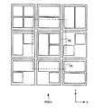
バッファ102は、ユーザが作成しようとする漫画のデータがページ毎に記憶され領域である。ここで記憶される情報(以下、バッファデータという)は、複数のページが並ぶ順番を示す配列(以下、ページ配列という)、および各ページの内容(画像の内容、画像の位置、サイズ、回転角度など)を含む。この例では、複数のページは、縦一列に並ぶ配列で規定される。例えば、4つのページ(PA、PB、PC、PD)が縦一列に並ぶ配列がバッファデータPSD1において規定されている(図4参照)。以下の説明において、バッファデータに規定されている複数のページ全体を、ページセットという場合がある。
The
表示制御部104は、バッファ102のバッファデータが示すページセットの少なくとも一部を、表示部14に表示させる。このとき、表示制御部104は、ページを表示させる画面の種類を、ユーザの操作に基づいて決定する。この例では、表示される画面の種類は、配列編集画面(図6参照)、ページ編集画面(図8参照)、および連続画像表示画面(図9参照)を含む。配列編集画面は、ページの順序を入れ替えてページ配列を変更したり、ページを削除したりするための画面である。ページ編集画面は、1つのページの内容を編集するための画面である。連続画像表示画面は、生成した連続画像を表示するための画面である。いずれの画面についても、詳細の説明は後述する。
The
配列変更部103は、ユーザの操作に基づいてページ配列の変更内容を特定し、バッファ102に記憶されているバッファデータのうちページ配列に関するデータを変更する。ページ配列の変更は、ページの入替処理、ページの削除処理、およびページの追加処理を含む。
The
図4は、本発明の第1実施形態におけるページ配列変更処理(入替処理)を説明する図である。配列変更部103は、バッファデータPSD1のページ配列において、例えば、ページPBとページPCとを入れ替えるための操作が行われると、ページPBとページPCとの位置が入れ替わったバッファデータPSD2に変更する。
FIG. 4 is a diagram illustrating a page arrangement changing process (replacement process) according to the first embodiment of the present invention. For example, when an operation for replacing page PB and page PC in the page array of buffer data PSD1 is performed,
図5は、本発明の第1実施形態におけるページ配列変更処理(削除処理)を説明する図である。配列変更部103は、バッファデータPSD1のページ配列において、例えば、ページPCを削除するための操作が行われると、ページPCを削除して、ページPCの直後に存在したページPDを、ページPCの位置に移動させたバッファデータPSD3に変更する。
FIG. 5 is a diagram illustrating a page layout changing process (deletion process) according to the first embodiment of the present invention. For example, when an operation for deleting the page PC is performed in the page array of the buffer data PSD1, the
図6は、本発明の第1実施形態における配列編集画面の表示例を示す図である。図6は、図4および図5におけるバッファデータPSD1のうち表示領域DAの部分が表示部14に表示されている例を示している。ユーザのスクロール操作によって表示領域DAの位置を変更して、表示部14に表示されるページの範囲を変更することができる。
FIG. 6 is a diagram showing a display example of the array editing screen in the first embodiment of the present invention. FIG. 6 shows an example in which the display area DA of the buffer data PSD1 in FIGS. 4 and 5 is displayed on the
表示部14に表示された配列編集画面には、入替操作画像EIC1、EIC2、削除操作画像DIC1、DIC2が表示されている。入替操作画像EIC1、EIC2は、隣接するページ間に表示されている。例えば、入替操作画像EIC1は、ページPBとページPCとの間に表示されている。削除操作画像DIC1、DIC2は、各ページに対応して表示されている。
On the array edit screen displayed on the
入替操作画像EIC1が操作されると、図4で示したように、ページPBとページPCとが入れ替わるようにページ配列が変更される。入替操作画像EIC2が操作されると、ページPCとページPDとが入れ替わるようにページ配列が変更される。すなわち、入替操作画像が操作されると、入替操作画像が表示されている位置の両側に位置するページを入れ替える。言い換えると、入替操作画像が表示される位置は、入れ替えるべき2つのページを特定する態様で表示されていることになる。 When the exchange operation image EIC1 is operated, as shown in FIG. 4, the page arrangement is changed so that the page PB and the page PC are exchanged. When the exchange operation image EIC2 is operated, the page arrangement is changed so that the page PC and the page PD are exchanged. That is, when the replacement operation image is operated, the pages located on both sides of the position where the replacement operation image is displayed are replaced. In other words, the position where the replacement operation image is displayed is displayed in a mode that specifies two pages to be replaced.
なお、この例では、ページPBとページPCとを入れ替えるための入替操作画像EIC1は、ページPBとページPCとの間に表示されていたが、別の位置に表示されていてもよい。例えば、入替操作画像EIC1は、ページPCの中心に対してページPBの側に表示されることによって、ページPBおよびページPCを入替対象のページとして特定してもよい。このとき、入替操作画像EIC1は、ページPCに重畳する位置に表示されていてもよいし、ページPBに重畳する位置に表示されていてもよい。 In this example, the exchange operation image EIC1 for exchanging the page PB and the page PC is displayed between the page PB and the page PC, but may be displayed at another position. For example, the replacement operation image EIC1 may be displayed on the page PB side with respect to the center of the page PC to specify the page PB and the page PC as replacement target pages. At this time, the replacement operation image EIC1 may be displayed at a position overlapping with the page PC or may be displayed at a position overlapping with the page PB.
また、入替操作画像EIC1の画像によって、ページPBおよびページPCを入替対象のページとして特定してもよい。例えば、入替操作画像EIC1に入替対象ページを特定するための文字を含むようにしてもよいし、画像の形状によって特定されるようにしてもよい。 Further, the page PB and the page PC may be specified as the pages to be replaced by the image of the replacement operation image EIC1. For example, the replacement operation image EIC1 may include characters for specifying the replacement target page, or may be specified by the shape of the image.
削除操作画像DIC1が操作されると、図5で示したように、ページPCが削除されるようにページ配列が変更される。削除操作画像DIC2が操作されると、ページPDが削除されるようにページ配列が変更される。すなわち、削除操作画像が操作されると、削除操作画像が表示されている位置のページを削除する。言い換えると、削除操作画像が表示される位置は、削除すべきページを特定する態様で表示されていることになる。 When the delete operation image DIC1 is operated, as shown in FIG. 5, the page arrangement is changed so that the page PC is deleted. When the delete operation image DIC2 is operated, the page arrangement is changed so that the page PD is deleted. That is, when the delete operation image is operated, the page at the position where the delete operation image is displayed is deleted. In other words, the position where the deletion operation image is displayed is displayed in a mode that specifies the page to be deleted.
図7は、本発明の第1実施形態における配列編集画面にページ終端部分が表示されている例を示す図である。図7に示す表示例は、図5に示すバッファデータPSD3において、表示領域DAが最終のページPDの下端を表示させている場合の例である。この場合には、ページPDの下側(隣接するページが存在しない側)に追加操作画像AICが表示されている。追加操作画像AICが操作されると、ページPDの下側に新たなページが作成される。なお、追加操作画像AICは、最初のページPAの上側(隣接するページが存在しない側)においても表示されるようにしてもよい。 FIG. 7 is a diagram showing an example in which the page end portion is displayed on the array editing screen in the first embodiment of the present invention. The display example shown in FIG. 7 is an example in which the display area DA is displaying the lower end of the final page PD in the buffer data PSD3 shown in FIG. In this case, the additional operation image AIC is displayed on the lower side of the page PD (the side where no adjacent page exists). When the additional operation image AIC is operated, a new page is created below the page PD. The additional operation image AIC may be displayed on the upper side of the first page PA (on the side where no adjacent page exists).
図3に戻って説明を続ける。編集処理部101は、ユーザの操作に基づいて編集対象となる1つのページを特定し、バッファ102に記憶されているバッファデータのうち編集対象のページの内容に関するデータを変更する。配列編集画面において、いずれかのページを特定する操作(例えば、このページの部分に指を接触させる操作)をすると、そのページが編集対象として決定される。
Returning to FIG. 3, the description will be continued. The
図8は、本発明の第1実施形態におけるページ編集画面の表示例を示す図である。図8は、編集対象としてページPDが特定された場合のページ編集画面の表示例を示している。この例では、編集対象のページPDは、配列編集画面において表示されているサイズよりも拡大して表示される。なお、図8に示す表示例においては、すでに編集が進んでいる状態を示している。以下、この図8を用いて、各操作画像の説明をするとともに、その操作画像の操作に伴う編集処理の内容を説明する。 FIG. 8 is a diagram showing a display example of a page edit screen in the first embodiment of the present invention. FIG. 8 shows a display example of the page edit screen when the page PD is specified as the edit target. In this example, the page PD to be edited is displayed in a larger size than the size displayed on the array edit screen. Note that the display example shown in FIG. 8 shows a state in which editing is already in progress. Hereinafter, each operation image will be described with reference to FIG. 8, and the contents of the editing process accompanying the operation of the operation image will be described.
この例では、表示部14に表示されたページ編集画面には、複数の種類の操作画像が表示されている。複数の種類の操作画像は、この例では、保存操作画像BS、配列変更操作画像BP、領域指定操作画像BC、画像追加操作画像BI、テキスト追加操作画像BT、および背景指定操作画像BBを含む。
In this example, a plurality of types of operation images are displayed on the page editing screen displayed on the
領域指定操作画像BCは、編集対象のページ(以下、図8の記載に対応して、ページPDという)において画像データを表示させることができる領域(コマ)を選択するための操作画像である。図8の例では、コマは、領域C1、C2に対応する。コマの配置(以下、コマ割という)については、様々なパターンがテンプレートとして記憶部12に記憶されている。図4に示す各ページにおいて、コマ割のパターンが例示されている。このコマの領域には、記憶部12に記憶されている画像データが示す画像を配置することができる。この画像は、コマの形状に対応してトリミングされる。コマは、大きさの変更、回転が可能である。コマにトリミングされる画像についても、大きさ、回転が可能である。図8の例では、コマの領域C2は回転処理がされている。
The area designation operation image BC is an operation image for selecting an area (frame) in which image data can be displayed on a page to be edited (hereinafter referred to as page PD corresponding to the description of FIG. 8). In the example of FIG. 8, the frames correspond to the areas C1 and C2. Regarding the arrangement of frames (hereinafter referred to as frame division), various patterns are stored in the
画像追加操作画像BIは、ページPDにおいて、コマとは関係なくアイコン画像を表示するための操作画像である。図8の例では、アイコン画像は、記憶部12に記憶されているアイコンデータが示す画像であり、画像G1、G2に対応する。アイコン画像は、コマにトリミングされた画像よりも上のレイヤで配置される。アイコン画像間においてのレイヤの上下関係は、ユーザの操作によって変更可能である。テキスト追加操作画像BTは、ページPDにおいて、文字画像を表示するための操作画像である。図8の例では、文字画像は、テキスト画像T1に対応する。上記のアイコン画像とほぼ同様の扱いである。背景指定操作画像BBは、ページPDにおいて、最も下のレイヤの画像を表示するための操作画像である。
The image addition operation image BI is an operation image for displaying the icon image on the page PD regardless of the frame. In the example of FIG. 8, the icon image is an image represented by the icon data stored in the
配列変更操作画像BPは、ページ編集画面における編集処理を終了して、配列編集画面に切り替えるための操作画像である。保存操作画像BSは、ページ編集画面における編集処理を終了して、バッファ102に記憶されているバッファデータが示すページセットに応じた画像データの生成を指示するための操作画像である。この例では、さらにページ編集画面から連続画像表示画面に移行する処理も行われる。
The array change operation image BP is an operation image for ending the editing process on the page edit screen and switching to the array edit screen. The save operation image BS is an operation image for instructing the generation of image data according to the page set indicated by the buffer data stored in the
図3に戻って説明を続ける。画像生成部107は、ユーザの操作に基づいてバッファ102に記憶されているバッファデータが示すページセットの画像データを生成する。この例では、画像生成部107は、個別画像データと連続画像データとを生成して、記憶部12に保存する。
Returning to FIG. 3, the description will be continued. The
個別画像データは、ページセットを構成する複数のページのそれぞれの画像を示すデータである。連続画像データは、個別画像データが示す各ページに対応する画像をページ配列に並べて接続して、連続画像としたデータである。個別画像データおよび連続画像データは、例えば、jpg、gif、png、bmpといったフォーマットで記録されるデータである。このようにして、記憶部12に保存された個別画像データおよび連続画像データは、上記のコマの領域において、コマにトリミングさせて表示させることもできる。なお、画像生成部107は、個別画像データおよび連続画像データのいずれか一方のみを生成してもよい。
The individual image data is data indicating each image of a plurality of pages that form a page set. The continuous image data is data in which images corresponding to each page indicated by the individual image data are arranged and connected in a page array to form a continuous image. The individual image data and the continuous image data are data recorded in formats such as jpg, gif, png, and bmp, for example. In this way, the individual image data and the continuous image data stored in the
また、このように画像データが生成されるときに、バッファ102に記憶されているバッファデータについても、記憶部12に保存してもよい。このデータを用いれば、再び編集を継続して行うこともできる。
Further, when the image data is generated in this way, the buffer data stored in the
図9は、本発明の第1実施形態における連続画像データおよび個別画像データを説明する図である。上述したように、個別画像データUD1、UD2、UD3、UD4は、それぞれ、ページPA、PB、PC、PDを示す画像を記録したデータである。連続画像データCDは、ページPA、PB、PC、PDをページ配列に並べて接続した画像を記録したデータである。すなわち、連続画像データCDは、個別画像データUD1、UD2、UD3、UD4をページ配列に並べて接続することによって、1つの画像として記録したデータである。 FIG. 9 is a diagram illustrating continuous image data and individual image data according to the first embodiment of the present invention. As described above, the individual image data UD1, UD2, UD3, UD4 are data in which images showing the pages PA, PB, PC, PD are recorded, respectively. The continuous image data CD is data in which an image in which pages PA, PB, PC, PD are arranged in a page array and connected is recorded. That is, the continuous image data CD is data recorded as one image by arranging and connecting the individual image data UD1, UD2, UD3, and UD4 in a page arrangement.
図10は、本発明の第1実施形態における連続画像表示画面の表示例を示す図である。上述のように、図8に示すページ編集画面において保存操作画像BSが操作されると、連続画像表示画面に移行する。この例では、連続画像データが示す連続画像のうち、図9に示す表示領域DAの部分が表示部14に表示されている。ユーザのスクロール操作によって表示領域DAの位置を変更して、表示部14に表示される連続画像の範囲を変更することができる。
FIG. 10 is a diagram showing a display example of the continuous image display screen in the first embodiment of the present invention. As described above, when the save operation image BS is operated on the page edit screen shown in FIG. 8, the screen shifts to the continuous image display screen. In this example, of the continuous images represented by the continuous image data, the display area DA shown in FIG. 9 is displayed on the
また、この例では、連続画像表示画面には、アップロード用の操作画像BN1、BN2、BN3が表示されている。アップロード用の操作画像を操作すると、それぞれの操作画像に対応付けて決められているサーバに、連続画像データをアップロードする。アップロード先のサーバは、例えば、ストレージサービスを提供するサーバ、SNSを提供するサーバなどである。SNSを提供するサーバにアップロードする場合には、予め登録されたユーザのタイムラインなどに、連続画像を表示させるようにしてもよく、さらにテキストデータを表示できるようにしてもよい。 Further, in this example, operation images BN1, BN2, and BN3 for upload are displayed on the continuous image display screen. When the operation image for upload is operated, the continuous image data is uploaded to the server determined in association with each operation image. The upload destination server is, for example, a server that provides a storage service, a server that provides an SNS, or the like. When uploading to a server that provides SNS, a continuous image may be displayed on a timeline of a user registered in advance, or text data may be displayed.
[編集機能100の動作]
続いて、上述した編集機能100において実行される処理の流れを、図11、図12に示すフローチャートを用いて説明する。
[Operation of editing function 100]
Next, the flow of processing executed in the
図11、図12は、本発明の第1実施形態における編集機能において実行される処理を示すフローチャートである。この処理は、制御部11によって編集機能100が実現されると開始される。まず、制御部11は、表示部14に配列編集画面を表示させる(ステップS100)。この状態で、制御部11は、ページ入替操作(入替操作画像への操作)、ページ削除操作(削除操作画像への操作)、ページ追加操作(追加操作画像への操作)、および編集対象ページの特定操作(ページを特定する操作)の検出を待つ第1待機状態となる(ステップS110;No、ステップS120;No、ステップS130;No、ステップS140;No)。
11 and 12 are flowcharts showing the processing executed in the editing function according to the first embodiment of the present invention. This process is started when the
ページ入替操作が検出されると(ステップS110;Yes)、制御部11は、ページ配列変更処理(入替処理)を行う(ステップS115)。ページ削除操作が検出されると(ステップS120;Yes)、制御部11は、ページ削除処理を行う(ステップS125)。ページ追加操作が検出されると(ステップS130;Yes)、制御部11は、ページ追加処理を行う(ステップS135)。これらの処理は、上述したように、配列変更部103において実行される処理である。いずれかの処理が行われると、再び第1待機状態(ステップS110;No、ステップS120;No、ステップS130;No、ステップS140;No)となる。
When the page replacement operation is detected (step S110; Yes), the
編集対象ページの特定操作が検出されると(ステップS140;Yes)、配列編集画面からページ編集画面に表示が切り替わる(ステップS200)。この状態で、制御部11は、編集操作(操作画像BC、CI、CT、BBなどへの操作)の検出、配列編集画面への移行操作(配列変更操作画像BPへの操作)の検出、および画像保存操作(保存操作画像BSへの操作)の検出を待つ第2待機状態となる(ステップS210;No、ステップS220;No、ステップS230;No)。
When the specific operation of the page to be edited is detected (step S140; Yes), the display is switched from the sequence edit screen to the page edit screen (step S200). In this state, the
編集操作が検出されると(ステップS210;Yes)、制御部11は、編集処理を行う(ステップS215)。この編集処理は、上述したように、編集処理部101において実行される処理である。編集処理が行われると、再び第2待機状態(ステップS210;No、ステップS220;No、ステップS230;No)となる。
When the editing operation is detected (step S210; Yes), the
配列編集画面への移行操作が検出されると(ステップS220;Yes)、ページ編集画面から配列編集画面に表示が切り替わる(ステップS100)。そして、再び第1待機状態(ステップS110;No、ステップS120;No、ステップS130;No、ステップS140;No)となる、画像保存操作が検出されると(ステップS230;Yes)、制御部11は、画像データを生成し(ステップS235)、ページ編集画面から連続画像表示画面に切り替えて編集機能100による処理を終了する。画像データを生成する処理は、上述したように、画像生成部107において実行される処理である。すなわち、連続画像データと個別画像データとが生成され、記憶部12に保存される。以上が編集機能100の動作についての説明である。
When the shift operation to the array edit screen is detected (step S220; Yes), the display is switched from the page edit screen to the array edit screen (step S100). When the image saving operation is detected again (step S110; No, step S120; No, step S130; No, step S140; No), the
以上の通り、本実施形態の編集機能100においては、複数のページを配列して並べられた状態の画像を示す画像データ(連続画像データ)を生成する。このとき、1つの画像全体をまとめて編集対象とするのではなく、所定の範囲毎に区切ったページ単位で編集をすることができる。また、ページ単位での入れ替えを、入替操作画像を操作するという簡易な操作によって実現することができる。この結果、画像の一部領域を編集しつつ、その一部領域を他の一部領域と入れ替えながら、全体を調整していくということが容易に実現でき、効率的な編集作業が可能となる。
As described above, in the
<第2実施形態>
第1実施形態においては、ページ配列は縦方向に一次元的に並べられるように規定されていた。ページ配列は横方向に並べられるように規定されていてもよいし、二次元的に並べられるように規定されていてもよい。第2実施形態では、二次元的に並べられたページ配列の場合について説明する。
<Second Embodiment>
In the first embodiment, the page arrangement is defined to be arranged one-dimensionally in the vertical direction. The page array may be defined to be arranged in the horizontal direction, or may be defined to be arranged two-dimensionally. In the second embodiment, a case of a two-dimensionally arranged page array will be described.
図13は、本発明の第2実施形態におけるページ配列の例を示す図である。図13に示すように、ページ配列は、複数のページが、x方向およびy方向に二次元的に並べられた配列である。したがって、バッファ102には、二次元的なページ配列のバッファデータPSD4が記憶される。
FIG. 13 is a diagram showing an example of a page arrangement in the second embodiment of the present invention. As shown in FIG. 13, the page array is an array in which a plurality of pages are two-dimensionally arranged in the x direction and the y direction. Therefore, the buffer data PSD4 having a two-dimensional page arrangement is stored in the
図14は、本発明の第2実施形態における配列編集画面の表示例を示す図である。図14は、図13におけるバッファデータPSD4のうち表示領域DAの部分が表示部14に表示されている例を示している。ユーザのスクロール操作によって表示領域DAの位置を変更して、表示部14に表示されるページの範囲を変更することができる。
FIG. 14 is a diagram showing a display example of an array editing screen in the second embodiment of the present invention. FIG. 14 shows an example in which the display area DA of the buffer data PSD4 in FIG. 13 is displayed on the
第1実施形態の図6で説明した配列編集画面と同様に、図14に示す配列編集画面においても、隣接するページ間には入替操作画像が表示され、各ページ対応して削除操作画像が表示されている。ページPEと上側のページとの位置を入れ替える場合には、入替操作画像EIC3を操作すればよい。ページPEと右側のページとの位置を入れ替える場合には、入替操作画像EIC5を操作すればよい。ページPEと右上側のページとの位置を入れ替える場合には、入替操作画像EIC4を操作すればよい。 Similar to the array edit screen described in FIG. 6 of the first embodiment, in the array edit screen shown in FIG. 14 as well, the replacement operation image is displayed between adjacent pages, and the delete operation image is displayed corresponding to each page. Has been done. When the positions of the page PE and the upper page are exchanged, the exchange operation image EIC3 may be operated. When the positions of the page PE and the page on the right side are interchanged, the interchange operation image EIC5 may be operated. When the positions of the page PE and the page on the upper right side are interchanged, the interchange operation image EIC4 may be operated.
<その他の実施形態>
上記の編集機能100を実現する装置は通信装置10として説明したが、必ずしも通信機能を備えていなくてもよい。すなわち、編集機能100を実現可能な制御部を有している情報処理装置であればよい。なお、上記実施形態における通信装置10は、情報処理装置の一例である。
<Other embodiments>
Although the device that realizes the
上記の各ページから得られる画像は、漫画を想定した画像として説明しているが、必ずしも漫画でなくてもよく、画像を用いたものであればよい。例えば、いわゆるパノラマ写真のような画像が、連続画像であるものとしてもよい。この場合、パノラマ画像を複数の領域に分割し、それぞれの領域を1ページとして定義すればよい。 The image obtained from each of the above pages is described as an image assuming a cartoon, but the image is not necessarily a cartoon and may be any image using an image. For example, an image such as a so-called panoramic photograph may be a continuous image. In this case, the panoramic image may be divided into a plurality of areas, and each area may be defined as one page.
10…通信装置、11…制御部、12…記憶部、14…表示部、15…タッチセンサ、16…スピーカ、17…マイクロフォン、18…通信モジュール、80…サーバ、100…編集機能、101…編集処理部、102…バッファ、103…配列変更部、104…表示制御部、107…画像生成部
10 ... Communication device, 11 ... Control part, 12 ... Storage part, 14 ... Display part, 15 ... Touch sensor, 16 ... Speaker, 17 ... Microphone, 18 ... Communication module, 80 ... Server, 100 ... Editing function, 101 ... Edit Processing unit, 102 ... Buffer, 103 ... Arrangement changing unit, 104 ... Display control unit, 107 ... Image generating unit
Claims (11)
前記入替操作画像への操作が受け付けられると、前記第1のページと前記第2のページと入れ替えて、前記配列を変更し、
前記複数のページのそれぞれの画像を前記配列にしたがって並べて接続することによって、1つの画像を示す画像データを生成すること
をコンピュータに実行させるためのプログラム。 Replacement for changing at least some pages of a plurality of pages arranged in a predetermined array and positions of first pages included in the some pages with positions of second pages to change the array The operation image is displayed on the display unit in a mode that specifies the first page and the second page,
When an operation on the replacement operation image is accepted, the first page and the second page are replaced with each other to change the array,
A program for causing a computer to generate image data representing one image by arranging and connecting images of the plurality of pages in accordance with the array.
前記入替操作画像は、前記第1のページの中心に対して、当該入替操作画像に応じて特定される前記第2のページの側に表示されることを特徴とする請求項1に記載のプログラム。 The second page is adjacent to the first page,
The program according to claim 1, wherein the replacement operation image is displayed on the side of the second page specified according to the replacement operation image, with respect to the center of the first page. .
を特定する態様でさらに表示されることを特徴とする請求項1に記載のプログラム。 The program according to claim 1, wherein a delete operation image for deleting the first page is further displayed on the display unit in a mode for specifying the first page.
前記編集対象のページに対する編集処理を実行すること、
をさらに前記コンピュータに機能させることを特徴とする請求項1に記載のプログラム。 Specify the page to be edited from the page displayed on the display unit,
Performing an edit process on the page to be edited,
The program according to claim 1, further causing the computer to function.
前記入替操作画像への操作が受け付けられると、前記第1のページと前記第2のページと入れ替えて、前記配列を変更する配列変更部と、
前記複数のページのそれぞれの画像を前記配列にしたがって並べて接続することによって、1つの画像を示す画像データを生成する画像生成部と、
を備えることを特徴とする情報処理装置。 Replacement for changing at least some pages of a plurality of pages arranged in a predetermined array and positions of first pages included in the some pages with positions of second pages to change the array A display control unit configured to display an operation image on the display unit in a manner that specifies the first page and the second page;
An array changing unit that, when an operation to the replacement operation image is received, replaces the first page with the second page and changes the array.
An image generation unit that generates image data representing one image by connecting and connecting the images of the plurality of pages according to the array,
An information processing apparatus comprising:
所定の配列に並べられた複数のページの少なくとも一部のページ、および当該一部のページに含まれる第1のページの位置を第2のページの位置と入れ替えて前記配列を変更するための入替操作画像を、当該第1のページと当該第2のページとを特定する態様で表示部に表示させ、
前記入替操作画像への操作が受け付けられると、前記第1のページと前記第2のページと入れ替えて、前記配列を変更し、
前記複数のページのそれぞれの画像を前記配列にしたがって並べて接続することによって、1つの画像を示す画像データを生成すること
を含むことを特徴とする情報処理方法。 An information processing method executed by a computer,
Replacement for changing at least some pages of a plurality of pages arranged in a predetermined array and positions of first pages included in the some pages with positions of second pages to change the array The operation image is displayed on the display unit in a mode that specifies the first page and the second page,
When an operation on the replacement operation image is accepted, the first page and the second page are replaced with each other to change the array,
An information processing method comprising: generating image data representing one image by arranging and connecting the images of the plurality of pages according to the arrangement.
Priority Applications (3)
| Application Number | Priority Date | Filing Date | Title |
|---|---|---|---|
| JP2015222282A JP6696758B2 (en) | 2015-11-12 | 2015-11-12 | Program, information processing apparatus, and information processing method |
| KR1020160116189A KR102581745B1 (en) | 2015-11-12 | 2016-09-09 | A data prcessing device, data processing method and computer readable storage medium |
| US15/342,187 US10275125B2 (en) | 2015-11-12 | 2016-11-03 | Image data generation apparatus and non-transitory computer-readable recording medium |
Applications Claiming Priority (1)
| Application Number | Priority Date | Filing Date | Title |
|---|---|---|---|
| JP2015222282A JP6696758B2 (en) | 2015-11-12 | 2015-11-12 | Program, information processing apparatus, and information processing method |
Publications (3)
| Publication Number | Publication Date |
|---|---|
| JP2017091320A JP2017091320A (en) | 2017-05-25 |
| JP2017091320A5 JP2017091320A5 (en) | 2018-11-29 |
| JP6696758B2 true JP6696758B2 (en) | 2020-05-20 |
Family
ID=58689973
Family Applications (1)
| Application Number | Title | Priority Date | Filing Date |
|---|---|---|---|
| JP2015222282A Expired - Fee Related JP6696758B2 (en) | 2015-11-12 | 2015-11-12 | Program, information processing apparatus, and information processing method |
Country Status (3)
| Country | Link |
|---|---|
| US (1) | US10275125B2 (en) |
| JP (1) | JP6696758B2 (en) |
| KR (1) | KR102581745B1 (en) |
Families Citing this family (1)
| Publication number | Priority date | Publication date | Assignee | Title |
|---|---|---|---|---|
| CN107368237A (en) * | 2017-07-19 | 2017-11-21 | 环球智达科技(北京)有限公司 | Layout method based on user interface presentation |
Family Cites Families (32)
| Publication number | Priority date | Publication date | Assignee | Title |
|---|---|---|---|---|
| GB9024526D0 (en) * | 1990-11-12 | 1991-01-02 | Eden Group Ltd | Electronic display apparatus |
| WO1996003686A1 (en) * | 1994-07-28 | 1996-02-08 | Hewlett-Packard Company | Page manipulation facility |
| JPH10105683A (en) | 1996-09-27 | 1998-04-24 | Casio Comput Co Ltd | Picture controller |
| JP2000194671A (en) | 1998-12-25 | 2000-07-14 | Hitachi Ltd | Autonomous object control system |
| US7002700B1 (en) * | 2000-09-14 | 2006-02-21 | Electronics For Imaging, Inc. | Method and system for merging scan files into a color workflow |
| US6924904B2 (en) * | 2001-02-20 | 2005-08-02 | Sharp Laboratories Of America, Inc. | Methods and systems for electronically gathering and organizing printable information |
| US6850247B1 (en) * | 2002-01-06 | 2005-02-01 | Apple Computer, Inc. | Method and apparatus for image acquisition, organization, manipulation, and publication |
| US20040105123A1 (en) * | 2002-12-02 | 2004-06-03 | Fritz Terry M. | Systems and methods for accessing information corresponding to print jobs |
| JP2005038164A (en) | 2003-07-14 | 2005-02-10 | Seiko Epson Corp | System, program and method for comic edition |
| EP1955197A4 (en) * | 2005-10-14 | 2011-03-02 | Uhlig Llc | Dynamic variable-content publishing |
| US7689933B1 (en) * | 2005-11-14 | 2010-03-30 | Adobe Systems Inc. | Methods and apparatus to preview content |
| US8276098B2 (en) * | 2006-12-22 | 2012-09-25 | Apple Inc. | Interactive image thumbnails |
| US8762882B2 (en) * | 2007-02-05 | 2014-06-24 | Sony Corporation | Information processing apparatus, control method for use therein, and computer program |
| JP5064091B2 (en) * | 2007-04-13 | 2012-10-31 | 株式会社Pfu | Scanner device and image reading display method |
| US8363234B2 (en) * | 2007-05-17 | 2013-01-29 | Canon Kabushiki Kaisha | Information processing apparatus, method, and program product with operation for editing template designating printer functions |
| US9633047B2 (en) * | 2007-09-26 | 2017-04-25 | Picaboo Corporation | Story flow system and method |
| US8862986B2 (en) * | 2007-10-01 | 2014-10-14 | Hewlett-Packard Development Company, L.P. | Arranging graphic objects on a page with relative position based control |
| US20090271731A1 (en) * | 2008-04-27 | 2009-10-29 | Htc Corporation | Electronic device and user interface display method thereof |
| US8782557B2 (en) * | 2008-06-26 | 2014-07-15 | Microsoft Corporation | Ordered multiple selection user interface |
| JP5149212B2 (en) * | 2009-01-28 | 2013-02-20 | ソニー株式会社 | Information processing apparatus, information processing method, and program |
| US20120284595A1 (en) * | 2009-11-25 | 2012-11-08 | Lyons Nicholas P | Automatic Page Layout System and Method |
| US9026932B1 (en) * | 2010-04-16 | 2015-05-05 | Amazon Technologies, Inc. | Edge navigation user interface |
| KR102033599B1 (en) * | 2010-12-28 | 2019-10-17 | 삼성전자주식회사 | Method for moving object between pages and interface apparatus |
| US8842057B2 (en) * | 2011-09-27 | 2014-09-23 | Z124 | Detail on triggers: transitional states |
| JP2013089198A (en) | 2011-10-21 | 2013-05-13 | Fujifilm Corp | Electronic comic editing device, method and program |
| US9747019B2 (en) * | 2012-02-24 | 2017-08-29 | Lg Electronics Inc. | Mobile terminal and control method thereof |
| US9015582B2 (en) * | 2012-05-01 | 2015-04-21 | Kabushiki Kaisha Toshiba | User interface for reordering thumbnails |
| US9785307B1 (en) * | 2012-09-27 | 2017-10-10 | Open Text Corporation | Reorder and selection persistence of displayed objects |
| US8799829B2 (en) * | 2012-09-28 | 2014-08-05 | Interactive Memories, Inc. | Methods and systems for background uploading of media files for improved user experience in production of media-based products |
| US20140095335A1 (en) * | 2012-09-28 | 2014-04-03 | Interactive Memories, Inc. | Method for Dynamic Invoicing of Print Vendors at Real-Time Negotiated or Advertised Pricing for Online Printing Services |
| US20140109012A1 (en) * | 2012-10-16 | 2014-04-17 | Microsoft Corporation | Thumbnail and document map based navigation in a document |
| KR20150021354A (en) * | 2013-08-20 | 2015-03-02 | 삼성전자주식회사 | Method for setting print option trough touch input and mobile device for performing the same |
-
2015
- 2015-11-12 JP JP2015222282A patent/JP6696758B2/en not_active Expired - Fee Related
-
2016
- 2016-09-09 KR KR1020160116189A patent/KR102581745B1/en active IP Right Grant
- 2016-11-03 US US15/342,187 patent/US10275125B2/en not_active Expired - Fee Related
Also Published As
| Publication number | Publication date |
|---|---|
| JP2017091320A (en) | 2017-05-25 |
| KR20170055906A (en) | 2017-05-22 |
| KR102581745B1 (en) | 2023-09-22 |
| US20170139563A1 (en) | 2017-05-18 |
| US10275125B2 (en) | 2019-04-30 |
Similar Documents
| Publication | Publication Date | Title |
|---|---|---|
| US20120206771A1 (en) | Imaging product layout method | |
| US20140129980A1 (en) | Display method and electronic device using the same | |
| US10061493B2 (en) | Method and device for creating and editing object-inserted images | |
| US20120179995A1 (en) | Image layout adjustment method | |
| US20120206496A1 (en) | System for imaging product layout | |
| JP2012008884A (en) | Editing device, and layout editing method and program in editing device | |
| JP6696758B2 (en) | Program, information processing apparatus, and information processing method | |
| JP6746450B2 (en) | Display control method and display device | |
| JP2017037416A (en) | Image processor, image processing method | |
| JP2007028137A (en) | Image editing device and method, and program | |
| US8687876B2 (en) | Stereoscopic image pasting system, and method and program for controlling operation of same | |
| JP4683322B2 (en) | Image display control apparatus and image display control program | |
| JP7073700B2 (en) | Image processing program, information processing device and image processing method | |
| US8878902B2 (en) | Stereoscopic image display control apparatus, and method and program for controlling operation of same | |
| US8933999B2 (en) | Stereoscopic image display control apparatus, and method and program for controlling operation of same | |
| JP2006140591A (en) | Image editor | |
| JP2014106596A (en) | Information processor, control method thereof, and program | |
| JP5677119B2 (en) | Photobook creation device and control method thereof | |
| JP2010008955A (en) | Image data editing device, image data editing method and computer program | |
| JP5990068B2 (en) | Control device, control method, and control program | |
| JP2017102217A (en) | Display device, display program and display method | |
| JP2017045322A (en) | Mobile terminal and program | |
| JP2022105573A (en) | Image processing program, information processing device, and image processing method | |
| JP2020074507A (en) | Information processing apparatus, recording system, and program | |
| JP2011203919A (en) | Editing image data generating device and editing image data generating method |
Legal Events
| Date | Code | Title | Description |
|---|---|---|---|
| A80 | Written request to apply exceptions to lack of novelty of invention |
Free format text: JAPANESE INTERMEDIATE CODE: A80 Effective date: 20151202 |
|
| A521 | Request for written amendment filed |
Free format text: JAPANESE INTERMEDIATE CODE: A523 Effective date: 20181016 |
|
| A621 | Written request for application examination |
Free format text: JAPANESE INTERMEDIATE CODE: A621 Effective date: 20181016 |
|
| A977 | Report on retrieval |
Free format text: JAPANESE INTERMEDIATE CODE: A971007 Effective date: 20191024 |
|
| A131 | Notification of reasons for refusal |
Free format text: JAPANESE INTERMEDIATE CODE: A131 Effective date: 20191112 |
|
| A521 | Request for written amendment filed |
Free format text: JAPANESE INTERMEDIATE CODE: A523 Effective date: 20191125 |
|
| TRDD | Decision of grant or rejection written | ||
| A01 | Written decision to grant a patent or to grant a registration (utility model) |
Free format text: JAPANESE INTERMEDIATE CODE: A01 Effective date: 20200414 |
|
| A61 | First payment of annual fees (during grant procedure) |
Free format text: JAPANESE INTERMEDIATE CODE: A61 Effective date: 20200423 |
|
| R150 | Certificate of patent or registration of utility model |
Ref document number: 6696758 Country of ref document: JP Free format text: JAPANESE INTERMEDIATE CODE: R150 |
|
| LAPS | Cancellation because of no payment of annual fees | ||
| S531 | Written request for registration of change of domicile |
Free format text: JAPANESE INTERMEDIATE CODE: R313531 |
|
| R370 | Written measure of declining of transfer procedure |
Free format text: JAPANESE INTERMEDIATE CODE: R370 |