JP6696006B2 - Vehicle control system, vehicle control method, and vehicle control program - Google Patents
Vehicle control system, vehicle control method, and vehicle control program Download PDFInfo
- Publication number
- JP6696006B2 JP6696006B2 JP2018565186A JP2018565186A JP6696006B2 JP 6696006 B2 JP6696006 B2 JP 6696006B2 JP 2018565186 A JP2018565186 A JP 2018565186A JP 2018565186 A JP2018565186 A JP 2018565186A JP 6696006 B2 JP6696006 B2 JP 6696006B2
- Authority
- JP
- Japan
- Prior art keywords
- gate
- vehicle
- information
- dynamic information
- unit
- Prior art date
- Legal status (The legal status is an assumption and is not a legal conclusion. Google has not performed a legal analysis and makes no representation as to the accuracy of the status listed.)
- Active
Links
- 238000000034 method Methods 0.000 title claims description 13
- 230000003068 static effect Effects 0.000 claims description 62
- 238000013459 approach Methods 0.000 claims description 26
- 238000004891 communication Methods 0.000 description 25
- 238000012937 correction Methods 0.000 description 17
- 238000010586 diagram Methods 0.000 description 12
- 230000009471 action Effects 0.000 description 10
- 238000001514 detection method Methods 0.000 description 10
- 230000008859 change Effects 0.000 description 6
- 230000006399 behavior Effects 0.000 description 5
- 230000002093 peripheral effect Effects 0.000 description 5
- 230000008569 process Effects 0.000 description 5
- 238000012545 processing Methods 0.000 description 5
- 230000001133 acceleration Effects 0.000 description 4
- 238000002485 combustion reaction Methods 0.000 description 3
- 230000006870 function Effects 0.000 description 3
- 238000003384 imaging method Methods 0.000 description 3
- 230000007246 mechanism Effects 0.000 description 3
- 230000005484 gravity Effects 0.000 description 2
- 238000004458 analytical method Methods 0.000 description 1
- 230000005540 biological transmission Effects 0.000 description 1
- 238000004364 calculation method Methods 0.000 description 1
- 230000001413 cellular effect Effects 0.000 description 1
- 230000000295 complement effect Effects 0.000 description 1
- 238000010276 construction Methods 0.000 description 1
- 230000036461 convulsion Effects 0.000 description 1
- 238000005516 engineering process Methods 0.000 description 1
- 239000000446 fuel Substances 0.000 description 1
- 238000007499 fusion processing Methods 0.000 description 1
- 238000003780 insertion Methods 0.000 description 1
- 230000037431 insertion Effects 0.000 description 1
- 230000010354 integration Effects 0.000 description 1
- 229910044991 metal oxide Inorganic materials 0.000 description 1
- 150000004706 metal oxides Chemical class 0.000 description 1
- 238000012986 modification Methods 0.000 description 1
- 230000004048 modification Effects 0.000 description 1
- 238000005070 sampling Methods 0.000 description 1
- 239000004065 semiconductor Substances 0.000 description 1
- 238000006467 substitution reaction Methods 0.000 description 1
Images


Classifications
-
- G—PHYSICS
- G05—CONTROLLING; REGULATING
- G05D—SYSTEMS FOR CONTROLLING OR REGULATING NON-ELECTRIC VARIABLES
- G05D1/00—Control of position, course, altitude or attitude of land, water, air or space vehicles, e.g. using automatic pilots
- G05D1/0088—Control of position, course, altitude or attitude of land, water, air or space vehicles, e.g. using automatic pilots characterized by the autonomous decision making process, e.g. artificial intelligence, predefined behaviours
-
- B—PERFORMING OPERATIONS; TRANSPORTING
- B60—VEHICLES IN GENERAL
- B60W—CONJOINT CONTROL OF VEHICLE SUB-UNITS OF DIFFERENT TYPE OR DIFFERENT FUNCTION; CONTROL SYSTEMS SPECIALLY ADAPTED FOR HYBRID VEHICLES; ROAD VEHICLE DRIVE CONTROL SYSTEMS FOR PURPOSES NOT RELATED TO THE CONTROL OF A PARTICULAR SUB-UNIT
- B60W60/00—Drive control systems specially adapted for autonomous road vehicles
- B60W60/001—Planning or execution of driving tasks
- B60W60/0015—Planning or execution of driving tasks specially adapted for safety
- B60W60/0018—Planning or execution of driving tasks specially adapted for safety by employing degraded modes, e.g. reducing speed, in response to suboptimal conditions
- B60W60/00184—Planning or execution of driving tasks specially adapted for safety by employing degraded modes, e.g. reducing speed, in response to suboptimal conditions related to infrastructure
-
- G—PHYSICS
- G01—MEASURING; TESTING
- G01C—MEASURING DISTANCES, LEVELS OR BEARINGS; SURVEYING; NAVIGATION; GYROSCOPIC INSTRUMENTS; PHOTOGRAMMETRY OR VIDEOGRAMMETRY
- G01C21/00—Navigation; Navigational instruments not provided for in groups G01C1/00 - G01C19/00
- G01C21/26—Navigation; Navigational instruments not provided for in groups G01C1/00 - G01C19/00 specially adapted for navigation in a road network
- G01C21/34—Route searching; Route guidance
-
- G—PHYSICS
- G05—CONTROLLING; REGULATING
- G05D—SYSTEMS FOR CONTROLLING OR REGULATING NON-ELECTRIC VARIABLES
- G05D1/00—Control of position, course, altitude or attitude of land, water, air or space vehicles, e.g. using automatic pilots
- G05D1/02—Control of position or course in two dimensions
- G05D1/021—Control of position or course in two dimensions specially adapted to land vehicles
- G05D1/0212—Control of position or course in two dimensions specially adapted to land vehicles with means for defining a desired trajectory
-
- G—PHYSICS
- G08—SIGNALLING
- G08G—TRAFFIC CONTROL SYSTEMS
- G08G1/00—Traffic control systems for road vehicles
- G08G1/09—Arrangements for giving variable traffic instructions
- G08G1/0962—Arrangements for giving variable traffic instructions having an indicator mounted inside the vehicle, e.g. giving voice messages
- G08G1/0967—Systems involving transmission of highway information, e.g. weather, speed limits
-
- B—PERFORMING OPERATIONS; TRANSPORTING
- B60—VEHICLES IN GENERAL
- B60W—CONJOINT CONTROL OF VEHICLE SUB-UNITS OF DIFFERENT TYPE OR DIFFERENT FUNCTION; CONTROL SYSTEMS SPECIALLY ADAPTED FOR HYBRID VEHICLES; ROAD VEHICLE DRIVE CONTROL SYSTEMS FOR PURPOSES NOT RELATED TO THE CONTROL OF A PARTICULAR SUB-UNIT
- B60W2552/00—Input parameters relating to infrastructure
- B60W2552/50—Barriers
-
- B—PERFORMING OPERATIONS; TRANSPORTING
- B60—VEHICLES IN GENERAL
- B60W—CONJOINT CONTROL OF VEHICLE SUB-UNITS OF DIFFERENT TYPE OR DIFFERENT FUNCTION; CONTROL SYSTEMS SPECIALLY ADAPTED FOR HYBRID VEHICLES; ROAD VEHICLE DRIVE CONTROL SYSTEMS FOR PURPOSES NOT RELATED TO THE CONTROL OF A PARTICULAR SUB-UNIT
- B60W2554/00—Input parameters relating to objects
- B60W2554/40—Dynamic objects, e.g. animals, windblown objects
- B60W2554/408—Traffic behavior, e.g. swarm
-
- B—PERFORMING OPERATIONS; TRANSPORTING
- B60—VEHICLES IN GENERAL
- B60W—CONJOINT CONTROL OF VEHICLE SUB-UNITS OF DIFFERENT TYPE OR DIFFERENT FUNCTION; CONTROL SYSTEMS SPECIALLY ADAPTED FOR HYBRID VEHICLES; ROAD VEHICLE DRIVE CONTROL SYSTEMS FOR PURPOSES NOT RELATED TO THE CONTROL OF A PARTICULAR SUB-UNIT
- B60W2556/00—Input parameters relating to data
- B60W2556/45—External transmission of data to or from the vehicle
- B60W2556/50—External transmission of data to or from the vehicle of positioning data, e.g. GPS [Global Positioning System] data
Landscapes
- Engineering & Computer Science (AREA)
- Radar, Positioning & Navigation (AREA)
- Remote Sensing (AREA)
- Physics & Mathematics (AREA)
- General Physics & Mathematics (AREA)
- Automation & Control Theory (AREA)
- Aviation & Aerospace Engineering (AREA)
- Game Theory and Decision Science (AREA)
- Evolutionary Computation (AREA)
- Atmospheric Sciences (AREA)
- Medical Informatics (AREA)
- Business, Economics & Management (AREA)
- Health & Medical Sciences (AREA)
- Artificial Intelligence (AREA)
- Life Sciences & Earth Sciences (AREA)
- Human Computer Interaction (AREA)
- Mechanical Engineering (AREA)
- Transportation (AREA)
- Traffic Control Systems (AREA)
- Control Of Driving Devices And Active Controlling Of Vehicle (AREA)
- Navigation (AREA)
Description
本発明は、車両制御システム、車両制御方法、および車両制御プログラムに関する。 The present invention relates to a vehicle control system, a vehicle control method, and a vehicle control program.
従来、車両に搭載された車載カメラにより撮像された画像を処理し、料金所における稼動中のゲートを認識し、認識されたゲートの中から何れか1つのゲートを特定し、車両の現在位置から特定されたゲートまでの走行ルートを仮想的な走行車線の態様で設定し、設定された走行ルートを走行ルート表示部に表示させるナビゲーション装置が知られている(例えば、特許文献1参照)。 Conventionally, an image captured by an in-vehicle camera mounted on a vehicle is processed to recognize an operating gate at a tollgate, identify any one of the recognized gates, and detect the current position of the vehicle. A navigation device is known in which a travel route to a specified gate is set in a virtual travel lane mode and the set travel route is displayed on a travel route display unit (for example, see Patent Document 1).
上記従来の技術では、車両の現在位置から最も近い稼働ゲートを特定することにより、最短の走行ルートを設定して案内するものとしているが、最短の走行ルートが最適な走行ルートであるとは限らない。 In the above-mentioned conventional technology, the shortest travel route is set and guided by identifying the operating gate closest to the current position of the vehicle, but the shortest travel route is not always the optimum travel route. Absent.
本発明は、このような事情を考慮してなされたものであり、より好適なゲートを選択することができる車両制御システム、車両制御方法、および車両制御プログラムを提供することを目的の一つとする。 The present invention has been made in consideration of such circumstances, and an object thereof is to provide a vehicle control system, a vehicle control method, and a vehicle control program capable of selecting a more suitable gate. ..
(1):ゲートに関する静的な情報であって、前記ゲートに自車両が接近する前に得られる静的情報を取得する静的情報取得部と、前記ゲートに関する動的な情報であって、前記ゲートに前記自車両が接近したときに得られる動的情報を取得する動的情報取得部と、前記静的情報取得部により取得された静的情報に基づいて、複数のゲートの中からゲートを選択し、選択したゲートに基づいて複数の本線のうちから前記自車両が走行する本線を決定し、決定した本線を前記自車両に走行させ、その後、前記動的情報取得部により取得された動的情報に基づいて、ゲートの選択結果を修正し、修正したゲートを通過するように車両の制御を行うゲート通過制御部とを備える車両制御システムである。 (1): static information about the gate, which is static information obtained before the host vehicle approaches the gate, and a dynamic information about the gate, Based on the static information acquired by the dynamic information acquisition unit that acquires the dynamic information obtained when the host vehicle approaches the gate, and the static information acquired by the static information acquisition unit, a gate from a plurality of gates Is selected, the main line on which the host vehicle travels is determined from among a plurality of main lines based on the selected gate, the determined main line is allowed to travel to the host vehicle, and then acquired by the dynamic information acquisition unit. The vehicle control system includes: a gate passage control unit that corrects a gate selection result based on dynamic information and controls the vehicle so that the vehicle passes through the corrected gate.
(2):ゲートに関する静的な情報であって、前記ゲートに自車両が接近する前に得られる静的情報を取得する静的情報取得部と、前記ゲートに関する動的な情報であって、前記ゲートに前記自車両が接近したときに得られる動的情報を取得する動的情報取得部と、前記静的情報取得部により取得された静的情報に基づいて、複数のゲートの中からゲートを選択し、その後、前記動的情報取得部により取得された動的情報に基づいて、ゲートの選択結果を修正する選択部と、前記選択部により選択されたゲートを通過するように車両の制御を行うゲート通過制御部と、を備え、前記選択部は、自車両の位置からゲートまでの距離、前記ゲートに進入する場合に到達目標とする到達目標位置と前記到達目標位置の周辺に存在する他車両との距離、および前記他車両と前記自車両との相対速度に基づいて、前記ゲートの選択結果を修正する車両制御システムである。 (2): static information about the gate, which is static information obtained before the host vehicle approaches the gate, and a dynamic information about the gate, Based on the static information acquired by the dynamic information acquisition unit that acquires the dynamic information obtained when the host vehicle approaches the gate, and the static information acquired by the static information acquisition unit, a gate from a plurality of gates And then, based on the dynamic information acquired by the dynamic information acquisition unit, a selection unit that corrects the selection result of the gate, and a vehicle control so as to pass through the gate selected by the selection unit. And a gate passage control unit for performing the following , wherein the selection unit is present in the distance from the position of the own vehicle to the gate, the arrival target position which is the arrival target when entering the gate, and the vicinity of the arrival target position. It is a vehicle control system that corrects a selection result of the gate based on a distance to another vehicle and a relative speed between the other vehicle and the own vehicle .
(3):上記(1)または(2)の車両制御システムであって、前記ゲートに前記自車両が接近する前に得られる情報は、ゲート構造、前記自車両の行先、またはETC車載機器を利用してゲートを通過することができるか否かを示す情報の少なくとも1つを含み、
前記ゲートに前記自車両が接近したときに得られる情報は、前記ゲートが利用可能な状態であるか否かを示す情報、または前記ゲートの混雑度合を示す情報の少なくとも1つを含む。
(3): In the vehicle control system according to (1) or (2) above, the information obtained before the host vehicle approaches the gate is the gate structure, the destination of the host vehicle, or the ETC in-vehicle device. Including at least one piece of information indicating whether or not it can be used to pass through the gate,
Information obtained when the own vehicle approaches the gate comprises at least one of information the gate indicating whether the available state or information indicating congestion degree of the gate.
(4):上記(2)の車両制御システムであって、前記動的情報取得部は、前記動的情報を繰り返し取得し、前記選択部は、前記ゲートの選択結果を繰り返し修正する。 (4): In the vehicle control system according to (2) above, the dynamic information acquisition unit repeatedly acquires the dynamic information, and the selection unit repeatedly corrects a selection result of the gate.
(5):車載コンピュータが、ゲートに関する静的な情報であって、前記ゲートに自車両が接近する前に得られる静的情報を取得し、前記ゲートに関する動的な情報であって、前記ゲートに前記自車両が接近したときに得られる動的情報を取得し、前記取得された静的情報に基づいて、複数のゲートの中からゲートを選択し、選択したゲートに基づいて複数の本線のうちから前記自車両が走行する本線を決定し、決定した本線を前記自車両に走行させ、その後、前記取得された動的情報に基づいて、ゲートの選択結果を修正し、修正したゲートを通過するように車両の制御を行う車両制御方法である。 (5): The in- vehicle computer obtains static information about the gate, which is static information obtained before the host vehicle approaches the gate, and is dynamic information about the gate, To obtain dynamic information obtained when the vehicle approaches, select a gate from a plurality of gates based on the obtained static information, and select a plurality of main lines based on the selected gate. The main line on which the own vehicle travels is determined, the determined main line is caused to travel to the own vehicle, and then the gate selection result is corrected based on the acquired dynamic information, and the corrected gate is passed. A vehicle control method for controlling a vehicle so that
(6):車載コンピュータに、ゲートに関する静的な情報であって、前記ゲートに自車両が接近する前に得られる静的情報を取得させ、前記ゲートに関する動的な情報であって、前記ゲートに前記自車両が接近したときに得られる動的情報を取得させ、前記取得された静的情報に基づいて、複数のゲートの中からゲートを選択させ、選択されたゲートに基づいて複数の本線のうちから前記自車両が走行する本線を決定させ、決定させた本線を前記自車両に走行させ、その後、前記取得された動的情報に基づいて、ゲートの選択結果を修正させ、修正したゲートを通過するように車両の制御を行わせるプログラムである。 (6): The vehicle-mounted computer acquires static information about the gate, which is static information obtained before the host vehicle approaches the gate, and is dynamic information about the gate. To acquire dynamic information obtained when the vehicle approaches, to select a gate from a plurality of gates based on the acquired static information, and to select a plurality of main lines based on the selected gate The main line on which the own vehicle travels is determined from among the above, the determined main line is caused to travel on the own vehicle, and then the selection result of the gate is corrected based on the acquired dynamic information, and the corrected gate This is a program that controls the vehicle so that it will pass through.
上記(1)−(6)によれば、車両制御システムは、静的な情報に基づいて選択されたゲートを、動的な情報に基づいて修正することにより、好適なゲートを選択することができる。 According to the above (1) to (6), the vehicle control system can select a suitable gate by correcting the gate selected based on the static information based on the dynamic information. it can.
上記(2)によれば、選択部が、自車両の位置からゲートまでの距離、ゲートに進入する場合に到達目標とする到達目標位置と前記到達目標位置の周辺に存在する他車両との距離、および他車両と自車両との相対速度に基づいて、ゲートを選択することにより、実際に自車両が通過することができるゲートを選択することができる。According to the above (2), the selection unit determines the distance from the position of the own vehicle to the gate, the distance to the arrival target position which is the arrival target when entering the gate, and the distance to other vehicles existing around the arrival target position. , And by selecting the gate based on the relative speed between the other vehicle and the own vehicle, the gate through which the own vehicle can actually pass can be selected.
上記(4)によれば、車両制御システムは、動的な情報に基づいてゲートの選択結果を繰り返し修正することにより、自車両の周辺の状況が変化した場合であっても、好適なゲートを選択することができる。According to the above (4), the vehicle control system repeatedly corrects the selection result of the gate based on the dynamic information, so that the suitable gate can be determined even when the situation around the vehicle changes. You can choose.
以下、図面を参照し、本発明の車両制御システム、車両制御方法、および車両制御プログラムの実施形態について説明する。 Hereinafter, embodiments of a vehicle control system, a vehicle control method, and a vehicle control program of the present invention will be described with reference to the drawings.
[全体構成]
図1は、自動運転制御ユニット100を含む車両システム1の構成図である。車両システム1が搭載される車両は、例えば、二輪や三輪、四輪等の車両であり、その駆動源は、ディーゼルエンジンやガソリンエンジンなどの内燃機関、電動機、或いはこれらの組み合わせである。電動機は、内燃機関に連結された発電機による発電電力、或いは二次電池や燃料電池の放電電力を使用して動作する。[overall structure]
FIG. 1 is a configuration diagram of a
車両システム1は、例えば、カメラ10と、レーダ装置12と、ファインダ14と、物体認識装置16と、通信装置20と、HMI(Human Machine Interface)30と、ETC(Electronic Toll Collection system)車載器40と、ナビゲーション装置50と、MPU(Micro-Processing Unit)60と、車両センサ70と、運転操作子80と、車室内カメラ90と、自動運転制御ユニット100と、走行駆動力出力装置200と、ブレーキ装置210と、ステアリング装置220とを備える。これらの装置や機器は、CAN(Controller Area Network)通信線等の多重通信線やシリアル通信線、無線通信網等によって互いに接続される。なお、図1に示す構成はあくまで一例であり、構成の一部が省略されてもよいし、更に別の構成が追加されてもよい。
The
カメラ10は、例えば、CCD(Charge Coupled Device)やCMOS(Complementary Metal Oxide Semiconductor)等の固体撮像素子を利用したデジタルカメラである。カメラ10は、車両システム1が搭載される車両(以下、自車両Mと称する)の任意の箇所に一つまたは複数が取り付けられる。前方を撮像する場合、カメラ10は、フロントウインドシールド上部やルームミラー裏面等に取り付けられる。カメラ10は、例えば、周期的に繰り返し自車両Mの周辺を撮像する。カメラ10は、ステレオカメラであってもよい。
The
レーダ装置12は、自車両Mの周辺にミリ波などの電波を放射すると共に、物体によって反射された電波(反射波)を検出して少なくとも物体の位置(距離および方位)を検出する。レーダ装置12は、自車両Mの任意の箇所に一つまたは複数が取り付けられる。レーダ装置12は、FM−CW(Frequency Modulated Continuous Wave)方式によって物体の位置および速度を検出してもよい。
The
ファインダ14は、照射光に対する散乱光を測定し、対象までの距離を検出するLIDAR(Light Detection and Ranging、或いはLaser Imaging Detection and Ranging)である。ファインダ14は、自車両Mの任意の箇所に一つまたは複数が取り付けられる。
The
物体認識装置16は、カメラ10、レーダ装置12、およびファインダ14のうち一部または全部による検出結果に対してセンサフュージョン処理を行って、物体の位置、種類、速度などを認識する。物体認識装置16は、認識結果を自動運転制御ユニット100に出力する。
The
通信装置20は、例えば、セルラー網やWi−Fi網、Bluetooth(登録商標)、DSRC(Dedicated Short Range Communication)などを利用して、自車両Mの周辺に存在する他車両と通信し、或いは無線基地局を介して各種サーバ装置と通信する。
The
HMI30は、自車両Mの乗員に対して各種情報を提示すると共に、乗員による入力操作を受け付ける。HMI30は、各種表示装置、スピーカ、ブザー、タッチパネル、スイッチ、キーなどを含む。 The HMI 30 presents various kinds of information to the occupant of the own vehicle M and receives an input operation by the occupant. The HMI 30 includes various display devices, speakers, buzzers, touch panels, switches, keys, and the like.
ETC車載器40は、ETC路側器と通信することで入口料金所や出口料金所などの情報を交換する。ETC車載器40は、ETCカードが装着される装着部と、装着部にETCカードが装着されているか否かを検出する検出部と、有料道路のゲートに設けられたETC路側器と通信する無線通信部と、通知部と、ETC制御部とを備える。ETCカードは、自車両Mが有料道路を通過するための認証情報(AI(authentication information))が格納された媒体である。無線通信部は、通信装置20と共通化されてもよい。
The ETC vehicle-mounted device 40 exchanges information such as an entrance toll gate and an exit toll gate by communicating with the ETC roadside device. The ETC vehicle-mounted device 40 includes a mounting unit to which an ETC card is mounted, a detection unit that detects whether or not the ETC card is mounted in the mounting unit, and a radio that communicates with an ETC roadside device provided at a toll road gate. A communication unit, a notification unit, and an ETC control unit are provided. The ETC card is a medium in which authentication information (AI (authentication information)) for the vehicle M to pass the toll road is stored. The wireless communication unit may be shared with the
装着部は、ETCカードを装着および抜き取りが可能である挿抜機構を備える。装着部において、ETCカードが装着された状態またはETCカードが抜き取られた状態のいずれであるかが、検出部により検出される。検出部は、検出結果を、ETC制御部の制御に基づいて、自動運転制御ユニット100に出力する。なお、検出部は、ETCカードの有効期限などに基づくETCカードの有効または無効を検出する機能部を備えていて良い。この場合、検出部は、ETCカードが有効である場合、ETCカードが装着されている状態であると判定し、ETCカードが無効である場合、ETCカードが装着されていない状態であると判定してもよい。
The mounting portion includes an insertion / removal mechanism that allows the ETC card to be mounted and removed. The detection unit detects whether the ETC card is attached or the ETC card is removed from the attachment unit. The detection unit outputs the detection result to the automatic
無線通信部は、ETC制御部の制御に基づいて、ETCカードに格納された認証情報をETC路側器に送信する。無線通信部は、ETC路側器から受信した認証結果に基づいて、ETC路側器が設けられたゲート通過の可否、入口料金所や出口料金所などの情報を取得する。ETC路側器は、ETC車載器から受信した情報を元に自車両Mの乗員に対する課金額を決定し、請求処理を進める。 The wireless communication unit transmits the authentication information stored in the ETC card to the ETC roadside device under the control of the ETC control unit. The wireless communication unit acquires information such as whether or not the gate can be passed where the ETC roadside device is provided, the entrance toll gate, and the exit tollgate, based on the authentication result received from the ETC roadside device. The ETC roadside device determines the charge amount for the occupant of the own vehicle M based on the information received from the ETC vehicle-mounted device, and proceeds the billing process.
通知部は、音声を出力するスピーカや、インジケータなどである。通知部は、ETCカードの装着状態、無線通信部により取得した認証結果を乗員に通知する。 The notification unit is a speaker that outputs voice, an indicator, or the like. The notification unit notifies the occupant of the mounted state of the ETC card and the authentication result acquired by the wireless communication unit.
ナビゲーション装置50は、例えば、GNSS(Global Navigation Satellite System)受信機51と、ナビHMI52と、経路決定部53とを備え、HDD(Hard Disk Drive)やフラッシュメモリなどの記憶装置に第1地図情報54を保持している。GNSS受信機は、GNSS衛星から受信した信号に基づいて、自車両Mの位置を特定する。自車両Mの位置は、車両センサ70の出力を利用したINS(Inertial Navigation System)によって特定または補完されてもよい。ナビHMI52は、表示装置、スピーカ、タッチパネル、キーなどを含む。ナビHMI52は、前述したHMI30と一部または全部が共通化されてもよい。経路決定部53は、例えば、GNSS受信機51により特定された自車両Mの位置(或いは入力された任意の位置)から、ナビHMI52を用いて乗員により入力された目的地までの経路を、第1地図情報54を参照して決定する。第1地図情報54は、例えば、道路を示すリンクと、リンクによって接続されたノードとによって道路形状が表現された情報である。第1地図情報54は、道路の曲率やPOI(Point Of Interest)情報などを含んでもよい。経路決定部53により決定された経路は、MPU60に出力される。また、ナビゲーション装置50は、経路決定部53により決定された経路に基づいて、ナビHMI52を用いた経路案内を行ってもよい。なお、ナビゲーション装置50は、例えば、ユーザの保有するスマートフォンやタブレット端末等の端末装置の機能によって実現されてもよい。また、ナビゲーション装置50は、通信装置20を介してナビゲーションサーバに現在位置と目的地を送信し、ナビゲーションサーバから返信された経路を取得してもよい。
The
MPU60は、例えば、推奨車線決定部61として機能し、HDDやフラッシュメモリなどの記憶装置に第2地図情報62を保持している。推奨車線決定部61は、ナビゲーション装置50から提供された経路を複数のブロックに分割し(例えば、車両進行方向に関して100[m]毎に分割し)、第2地図情報62を参照してブロックごとに目標車線を決定する。推奨車線決定部61は、左から何番目の車線を走行するといった決定を行う。推奨車線決定部61は、経路において分岐箇所や合流箇所などが存在する場合、自車両Mが、分岐先に進行するための合理的な経路を走行できるように、推奨車線を決定する。
The
第2地図情報62は、第1地図情報54よりも高精度な地図情報である。第2地図情報62は、例えば、車線の中央の情報あるいは車線の境界の情報等を含んでいる。また、第2地図情報62には、道路情報、交通規制情報、住所情報(住所・郵便番号)、施設情報、電話番号情報などが含まれてよい。道路情報には、高速道路、有料道路、国道、都道府県道といった道路の種別を表す情報や、道路の車線数、各車線の幅員、道路の勾配、道路の位置(経度、緯度、高さを含む3次元座標)、車線のカーブの曲率、車線の合流および分岐ポイントの位置、道路に設けられた標識等の情報が含まれる。第2地図情報62は、通信装置20を用いて他装置にアクセスすることにより、随時、アップデートされてよい。
The
また、第2地図情報62には、入口料金所や出口料金所などのゲート構造を示す情報が記憶されている。ゲート構造を示す情報は、例えば、料金所に設けられたゲートの数や、ゲートの位置を示す情報、ゲートの種別を示す情報(ETC専用ゲート、一般ゲートなどの情報)である。
Further, the
車両センサ70は、自車両Mの速度を検出する車速センサ、加速度を検出する加速度センサ、鉛直軸回りの角速度を検出するヨーレートセンサ、自車両Mの向きを検出する方位センサ等を含む。
The
運転操作子80は、例えば、アクセルペダル、ブレーキペダル、シフトレバー、ステアリングホイールその他の操作子を含む。運転操作子80には、操作量あるいは操作の有無を検出するセンサが取り付けられており、その検出結果は、自動運転制御ユニット100、もしくは、走行駆動力出力装置200、ブレーキ装置210、およびステアリング装置220のうち一方または双方に出力される。
The
車室内カメラ90は、運転席に着座した乗員の顔を中心として上半身を撮像する。車室内カメラ90の撮像画像は、自動運転制御ユニット100に出力される。
The
自動運転制御ユニット100は、例えば、第1制御部120と、第2制御部140とを備える。第1制御部120と第2制御部140は、それぞれ、CPU(Central Processing Unit)などのプロセッサがプログラム(ソフトウェア)を実行することで実現される。また、各機能部のうち一部または全部は、LSI(Large Scale Integration)やASIC(Application Specific Integrated Circuit)、FPGA(Field-Programmable Gate Array)などのハードウェアによって実現されてもよいし、ソフトウェアとハードウェアの協働によって実現されてもよい。
The automatic
第1制御部120は、例えば、外界認識部121と、自車位置認識部122と、行動計画生成部123とを備える。
The
外界認識部121は、カメラ10、レーダ装置12、およびファインダ14から物体認識装置16を介して入力される情報に基づいて、周辺車両の位置、および速度、加速度等の状態を認識する。周辺車両の位置は、その周辺車両の重心やコーナー等の代表点で表されてもよいし、周辺車両の輪郭で表現された領域で表されてもよい。周辺車両の「状態」とは、周辺車両の加速度やジャーク、あるいは「行動状態」(例えば車線変更をしている、またはしようとしているか否か)を含んでもよい。また、外界認識部121は、周辺車両に加えて、ガードレールや電柱、駐車車両、歩行者その他の物体の位置を認識してもよい。
The external
自車位置認識部122は、例えば、自車両Mが走行している車線(走行車線)、並びに走行車線に対する自車両Mの相対位置および姿勢を認識する。自車位置認識部122は、例えば、第2地図情報62から得られる道路区画線のパターン(例えば実線と破線の配列)と、カメラ10によって撮像された画像から認識される自車両Mの周辺の道路区画線のパターンとを比較することで、走行車線を認識する。この認識において、ナビゲーション装置50から取得される自車両Mの位置やINSによる処理結果が加味されてもよい。
The host vehicle
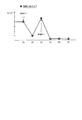
そして、自車位置認識部122は、例えば、走行車線に対する自車両Mの位置や姿勢を認識する。図2は、自車位置認識部122により走行車線L1に対する自車両Mの相対位置および姿勢が認識される様子を示す図である。自車位置認識部122は、例えば、自車両Mの基準点(例えば重心)の走行車線中央CLからの乖離OS、および自車両Mの進行方向の走行車線中央CLを連ねた線に対してなす角度θを、走行車線L1に対する自車両Mの相対位置および姿勢として認識する。なお、これに代えて、自車位置認識部122は、自車線L1のいずれかの側端部に対する自車両Mの基準点の位置などを、走行車線に対する自車両Mの相対位置として認識してもよい。自車位置認識部122により認識される自車両Mの相対位置は、推奨車線決定部61および行動計画生成部123に提供される。
Then, the own vehicle
行動計画生成部123は、推奨車線決定部61により決定された推奨車線を走行するように、且つ、自車両Mの周辺状況に対応できるように、自動運転において順次実行されるイベントを決定する。イベントには、例えば、一定速度で同じ走行車線を走行する定速走行イベント、前走車両に追従する追従走行イベント、車線変更イベント、合流イベント、分岐イベント、緊急停止イベント、自動運転を終了して手動運転に切り替えるためのハンドオーバイベント、料金所を通過するときに実行される料金所イベント(後述)などがある。また、これらのイベントの実行中に、自車両Mの周辺状況(周辺車両や歩行者の存在、道路工事による車線狭窄など)に基づいて、回避のための行動が計画される場合もある。
The action
行動計画生成部123は、自車両Mが将来走行する目標軌道を生成する。目標軌道は、例えば、速度要素を含んでいる。例えば、目標軌道は、所定のサンプリング時間(例えば0コンマ数[sec]程度)ごとに将来の基準時刻を複数設定し、それらの基準時刻に到達すべき目標地点(軌道点)の集合として生成される。このため、軌道点同士の間隔が広い場合、その軌道点の間の区間を高速に走行することを示している。
The action
図3は、推奨車線に基づいて目標軌道が生成される様子を示す図である。図示するように、推奨車線は、目的地までの経路に沿って走行するのに都合が良いように設定される。行動計画生成部123は、推奨車線の切り替わり地点の所定距離手前(イベントの種類に応じて決定されてよい)に差し掛かると、車線変更イベント、分岐イベント、合流イベントなどを起動する。各イベントの実行中に、障害物を回避する必要が生じた場合には、図示するように回避軌道が生成される。
FIG. 3 is a diagram showing how the target trajectory is generated based on the recommended lane. As shown, the recommended lane is set so that it is convenient to drive along the route to the destination. The action
行動計画生成部123は、例えば、目標軌道の候補を複数生成し、安全性と効率性の観点に基づいて、その時点での最適な目標軌道を選択する。
The action
また、行動計画生成部123は、サブ機能としてゲート通過制御部123Aを含む。ゲート通過制御部123Aの詳細については後述する。
The action
第2制御部140は、走行制御部141を備える。走行制御部141は、行動計画生成部123によって生成された目標軌道を、予定の時刻通りに自車両Mが通過するように、走行駆動力出力装置200、ブレーキ装置210、およびステアリング装置220を制御する。
The
走行駆動力出力装置200は、車両が走行するための走行駆動力(トルク)を駆動輪に出力する。走行駆動力出力装置200は、例えば、内燃機関、電動機、および変速機などの組み合わせと、これらを制御するECUとを備える。ECUは、走行制御部141から入力される情報、或いは運転操作子80から入力される情報に従って、上記の構成を制御する。
The traveling drive
ブレーキ装置210は、例えば、ブレーキキャリパーと、ブレーキキャリパーに油圧を伝達するシリンダと、シリンダに油圧を発生させる電動モータと、ブレーキECUとを備える。ブレーキECUは、走行制御部141から入力される情報、或いは運転操作子80から入力される情報に従って電動モータを制御し、制動操作に応じたブレーキトルクが各車輪に出力されるようにする。ブレーキ装置210は、運転操作子80に含まれるブレーキペダルの操作によって発生させた油圧を、マスターシリンダを介してシリンダに伝達する機構をバックアップとして備えてよい。なお、ブレーキ装置210は、上記説明した構成に限らず、走行制御部141から入力される情報に従ってアクチュエータを制御して、マスターシリンダの油圧をシリンダに伝達する電子制御式油圧ブレーキ装置であってもよい。
The
ステアリング装置220は、例えば、ステアリングECUと、電動モータとを備える。電動モータは、例えば、ラックアンドピニオン機構に力を作用させて転舵輪の向きを変更する。ステアリングECUは、走行制御部141から入力される情報、或いは運転操作子80から入力される情報に従って、電動モータを駆動し、転舵輪の向きを変更させる。
The
[ゲート通過制御部の詳細]
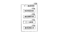
ゲート通過制御部123Aは、通過するゲートを選択し、選択したゲートを通過するように車両の制御を行う。図4は、ゲート通過制御部123Aの機能構成図である。ゲート通過制御部123Aは、静的情報取得部123aと、動的情報取得部123bと、ゲート選択部123cと、選択結果修正部123dとを含む。ゲート通過制御部123Aの機能の一部は、MPU60により実行されてもよい。例えば、静的情報取得部123aおよびゲート選択部123cは、MPU60に含まれてもよい。[Details of gate passage control section]
The gate
静的情報取得部123aは、ゲートに関する静的な情報である静的情報を取得する。動的情報取得部123bは、ゲートに関する動的な情報である動的情報を取得する。図5は、静的情報および動的情報について説明するための図である。静的情報は、ゲートに自車両Mが接近する前に得られる情報であり、動的情報は、ゲートに自車両Mが接近したときに得られる情報である。静的情報は、例えば、ナビゲーション装置50から得られる自車両Mの目的地(行先)や経路に関する情報、ETC車載器40から得られるETC車載器の利用の可否を示す情報、高精度地図情報62から得られるゲート構造を示す情報(ゲートの位置、数、ゲートの種別)などを含む。
The static
動的情報は、例えば、カメラ10より撮像された画像の解析結果に基づいて取得された、ゲートの有効または無効を示す情報、ゲートの周辺車両の位置や速度を示す情報、ゲートの混雑度合を示す情報、自車位置認識部122により認識された自車両Mの位置情報などを含む。この自車両Mの位置情報は、自車両Mの位置からゲートまたはゲート付近の路面標示までの距離を導出するための情報である。
The dynamic information is, for example, information indicating whether the gate is valid or invalid, information indicating the position and speed of a vehicle around the gate, and a congestion degree of the gate, which are acquired based on an analysis result of an image captured by the
また、ゲートの有効または無効を示す情報、ゲートの周辺車両の位置や速度を示す情報、ゲートの混雑度合を示す情報は、通信装置20を介して取得されてもよい。通信装置20は、例えば、ゲート付近に設けられた路側通信装置からゲートの有効または無効を示す情報またはゲートの周辺車両の位置や速度を示す情報を取得する。路側通信装置は、ゲートの手前の領域を撮像するカメラにより撮像された画像を通信装置20に送信する。また、通信装置20は、無線通信を用いてネットワークに接続されたサーバ装置等から、ゲートの有効または無効を示す情報や、ゲートの周辺車両の位置や速度を示す情報、ゲートの混雑度合を示す情報等を取得してもよい。
Further, the information indicating whether the gate is valid or invalid, the information indicating the position or speed of the vehicle around the gate, and the information indicating the congestion degree of the gate may be acquired via the
なお、ゲートに自車両Mが接近する前に通信装置20により取得された情報は、静的情報として分類され、ゲートに自車両Mが近づいたときに通信装置20により取得された情報は動的情報として分類される。また、例えばゲートの種別を示す情報や、ゲートの有効または無効を示す情報、ゲートの周辺車両の位置や速度を示す情報、ゲート前の混雑度合等が、ゲートに自車両Mが接近する前に取得される情報である場合は静的情報として分類され、ゲートに自車両Mが近づいたときに取得される情報は動的情報として分類される。
The information acquired by the
ゲート選択部123cは、静的情報取得部123bにより取得された静的情報に基づいて、複数のゲートの中からゲートを選択する。
The gate selection unit 123c selects a gate from a plurality of gates based on the static information acquired by the static
選択結果修正部123dは、動的情報取得部123bにより取得された動的情報に基づいて、ゲート選択部123cにより選択された選択結果を修正する。選択結果修正部123dは、例えば、動的情報に基づいて、ゲート選択部123cにより選択されたゲートを、より好適となるゲートに変更する。好適となるゲートとは、自車両Mがより滑らかに走行しながら通過することができるゲートや、混雑度合が他のゲートに比して低いゲートである。ゲート通過制御部123Aは、選択結果修正部123dにより選択されたゲートを通過するように自車両Mの制御を行う。
The selection
図6は、ゲート通過制御部123Aにより実行される処理の流れを示すフローチャートである。具体的な自車両Mの挙動については図7を参照して説明する。
FIG. 6 is a flowchart showing the flow of processing executed by the gate
まず、ゲート通過制御部123Aが、料金所イベントが起動するタイミングが到来したか否かを判定する(ステップS100)。料金所イベントが起動するタイミングが到来すると、静的情報取得部123aが、静的情報を取得する(ステップS102)。次に、ゲート選択部123cは、ステップS102で取得された静的情報に基づいて、通過する予定のゲートを選択する(ステップS104)。なお、ゲート選択部123cは、自車両Mの目的地に基づいて走行する車線を決定し、決定した車線を加味して通過するゲートを選択してもよい。次に、動的情報取得部123bは、動的情報が取得することができるまで待機する(ステップS106)。
First, the gate
動的情報が取得されると、選択結果修正部123dが、ステップS106で取得された動的情報に基づいて、ステップS104の選択結果を修正する必要があるか否かを判定する(ステップS108)。選択結果を修正する必要がある場合、選択結果修正部123dが、ステップS106で取得した動的情報に基づいて、選択結果を修正し(ステップS110)、ステップS112の処理に進む。選択結果を修正する必要がない場合、ゲート通過制御部123Aが、自車両Mがゲートに到達したか否かを判定する(ステップS112)。ゲートに到達していない場合、ステップS106の処理に戻り、ゲートに到達した場合、本フローチャートの処理は終了する。
When the dynamic information is acquired, the selection
図7は、料金所を通過する際の自車両Mの挙動の一例を示す図である。図中の料金所において、ゲート(1)から(6)が設けられており、ゲート(1)、(3)、(4)および(6)はETC専用ゲートであり、ゲート(2)および(4)は一般ゲートであるものとする。また、ゲート通過後において、道路は、A方面に向かう道路と、B方面に向かう道路とに分岐しているものとする。 FIG. 7: is a figure which shows an example of the behavior of the own vehicle M when passing a tollgate. At the toll gate in the figure, gates (1) to (6) are provided, and gates (1), (3), (4) and (6) are ETC exclusive gates, and gates (2) and (6). 4) is a general gate. Further, after passing through the gate, the road is divided into a road heading in the direction A and a road heading in the direction B.
時刻tにおいて、自車両Mにおいて設定されている目的地はA方面にあるため、ナビゲーション装置50によってA方面に向かう経路が設定されているものとする。また、自車両Mは、ETC車載器40を利用してゲートを通過する予定であり、ゲートの手前の本線L2を走行しているものとする。
At time t, since the destination set in the host vehicle M is in the direction A, it is assumed that the
時刻tにおいて、自車両Mが、ゲートから第1所定距離手前に到達すると、ゲート通過制御部123Aは、料金所イベントを起動させ、静的情報取得部123aが、静的情報を取得する。この場合、ゲート選択部123cは、静的情報に基づいて、静的スコアをゲートに対して付与する。
At time t, when the host vehicle M arrives before the first predetermined distance from the gate, the gate
図8は、静的スコアの一例を示す図である。横軸はゲートの識別情報を示し、縦軸はスコアを示している。ゲート選択部123cは、例えば、目的地へ進行しやすいという観点で静的スコアを各ゲートに付与する。ゲート選択部123cは、ゲート(3)に対して付与するスコアを最も高くし、ゲート(1)に対して付与するスコアを次に高くする。ゲート(3)を通過することにより、自車両Mの現在地から自車両MがA方面に向かう場合において、通過する経路が最も短くなり、且つ車両の挙動の変化が小さくなるためである。なお、静的スコアは、これに限らず、目的地に進行しやすいという観点で算出され、その算出方法の詳細については種々の手法が採用されてよい。ゲート選択部123cは、ゲートに対して付与したスコアに基づいて、A方面に向かうのに最も効率的なゲート(3)を、通過する予定のゲートとして選択する。そして、ゲート通過制御部123Aは、車線L2からゲート(3)を通過しやすい車線L1に自車両Mを車線変更させる。
FIG. 8 is a diagram showing an example of the static score. The horizontal axis shows the identification information of the gate, and the vertical axis shows the score. The gate selection unit 123c assigns a static score to each gate, for example, from the viewpoint of easy progress to the destination. The gate selection unit 123c makes the score given to the gate (3) the highest and the score given to the gate (1) the next highest. This is because by passing through the gate (3), when the host vehicle M heads in the direction A from the current position of the host vehicle M, the route that the host vehicle M passes through becomes the shortest and the change in the behavior of the vehicle becomes small. The static score is not limited to this, and is calculated from the viewpoint that it is easy to proceed to the destination, and various methods may be adopted for the details of the calculation method. The gate selection unit 123c selects the gate (3), which is the most efficient for moving toward the direction A, as the gate to pass through based on the score given to the gate. Then, the gate
時刻t+1において、自車両Mが、ゲートから(第1所定距離より短い)第2所定距離手前に到達すると、動的情報取得部123bは、動的情報として、ゲートの有効または無効を示す情報や、ゲートに向かって車列を形成している車両の状態、ゲートに向かって走行している車両の状態、ゲートの種別等を取得する。ここでゲートの種別は、静的情報として取得することができる場合があるが、ゲートの種別は時間帯や交通状況により変更されることがあるため、ゲートの種別は静的情報として取得されると共に、動的情報としても取得されてよい。
At
ゲート選択部123cは、動的情報に基づいて、静的スコアに対して動的スコアを加算して統合スコアをゲートに対して付与する。図9は、動的スコアの一例を示す図である。横軸はゲートの識別情報を示し、縦軸はスコアを示している。選択結果修正部123dは、例えば、混雑度が低い、ゲートに到達するまでに時間が短い、仮想的な車線変更の回数が少ないなどといった観点で動的スコアを各ゲートに付与する。選択結果修正部123dは、ゲート(1)に対して付与するスコアを最も高くし、ゲート(3)に対して付与するスコアを次に高くする。ゲート(3)には複数の車両が並んでおり、ゲート(1)には車両が並んでいないことから、ゲート(1)を通過すると円滑にゲートを通過することができるためである。そして、選択結果修正部123dは、ゲートに対して付与したスコアに基づいて、自車両Mが通過する予定のゲートを、ゲート(3)からゲート(1)に修正する。なお、選択結果修正部123dは、ゲートに向かって車列が形成されているときにゲートに対してスコアを付与する場合、車列に含まれる車両の移動速度が速い車列に対応するゲートに高いスコアを付与してもよい。
The gate selection unit 123c adds the dynamic score to the static score based on the dynamic information and gives the integrated score to the gate. FIG. 9 is a diagram showing an example of the dynamic score. The horizontal axis shows the identification information of the gate, and the vertical axis shows the score. The selection
また、選択結果修正部123dは、例えば、更に自車両Mからゲート(1)までの距離や、ゲート(1)を通過する場合に走行する経路(到達目標位置)と走行する経路の周辺に存在する(または存在することとなると推定される)周辺車両との距離、上記の周辺車両と自車両Mとの相対速度等を加味して、通過するゲートを選択(修正)してもよい。例えば、選択結果修正部123dは、ゲート(1)までの距離が十分あり、ゲート(1)を通過する場合に走行する経路を自車両Mが走行した場合に、自車両Mと周辺車両との距離が所定距離以上となるとき、ゲート(1)を通過することができると判定し、スコアが最も高いゲート(1)を通過するゲートとして選択する。そして、ゲート通過制御部123Aは、そのゲートまでの目標軌道を生成し、その目標軌道が不適切でなければ、ゲート(1)を通過する。
Further, the selection
一方、選択結果修正部123dは、自車両Mからゲート(1)までの距離が近い場合や、ゲート(1)を通過する場合に走行する経路から所定距離以内に周辺車両が存在する場合は、ゲート(1)は通過するゲートとしては不適切であると判定し、通過するゲートからゲート(1)を除外する。この場合、ゲート通過制御部123Aは、ゲート(1)とは異なるゲート(例えばゲート(1)の次にスコアが高いゲート)を選択する。
On the other hand, when the distance from the host vehicle M to the gate (1) is short, or when a surrounding vehicle exists within a predetermined distance from the route traveled when passing through the gate (1), the selection
そして、ゲート通過制御部123Aは、そのゲートまでの目標軌道を生成し、その目標軌道が不適切でなければ(例えば操舵角が許容範囲を超えなければ)目標軌道を走行するように自車両Mを制御する。
Then, the gate
また、選択結果修正部123dは、上記の処理を繰り返し、動的情報に基づいて、選択結果を修正してゲートを選択する。図10は、選択されたゲートが修正される場面の一例を示す図である。例えば、時刻t+2において(時刻t+1の自車両Mについては図7参照)、ゲート(3)に向かっていた他車両m1が、ゲート(1)に向かうように進行方向を変更した場合、選択結果修正部123dは、ゲート(1)に対して付与するスコアを時刻t+1で付与したスコアに比して低く付与し、ゲート(3)に対して付与したスコアを時刻t+1で付与したスコアに比して高く付与する。ゲート(1)には他車両m1が並んだことによりゲート(1)の車列が長くなり、ゲート(3)の車列が短くなったためである。図11は、時刻t+2においけるスコアの一例を示す図である。
In addition, the selection
そして、ゲート通過制御部123Aは、スコアが高くなったゲート(3)に進入するための目標軌道を生成する。例えば、ゲート通過制御部123Aは、目標軌道に沿って自車両Mをターゲット領域TA(図10参照)に移動させる。
Then, the gate
この場合、例えば、ゲート通過制御部123Aは、ターゲット領域TAの後方からターゲット領域TAに進入しようとしている他車両m2の前端とターゲット領域TAの後端との距離、自車両Mの後端と他車両m2の前端との距離、および自車両Mとゲート(3)(またはターゲット領域TAの直前の他車両)との距離に基づいて、安全性と効率性の観点を加味して、ゲート(3)を通過することが適切であるか否かを判定する。ゲート(3)を通過することが適切であると判定した場合は、ゲート通過制御部123Aは、自車両Mをターゲット領域TAに進行させてゲート(3)を通過させる制御を行う。一方、ゲート(3)を通過することが適切でないと判定した場合は、ゲート通過制御部123Aは、例えば、ゲート(3)の次にスコアが高いゲート(1)を通過させるように自車両Mを制御する。
In this case, for example, the gate
以上説明した実施形態によれば、ゲート選択部123cが、静的情報取得部123aにより取得された静的情報に基づいて、複数のゲートの中からゲートを選択し、その後、選択結果修正部123dが、動的情報取得部123bにより取得された動的情報に基づいて、ゲート選択部123cの選択結果を修正することにより、好適なゲートを選択することができる。
According to the embodiment described above, the gate selection unit 123c selects a gate from a plurality of gates based on the static information acquired by the static
以上、本発明を実施するための形態について実施形態を用いて説明したが、本発明はこうした実施形態に何等限定されるものではなく、本発明の要旨を逸脱しない範囲内において種々の変形及び置換を加えることができる。 Although the embodiments for carrying out the present invention have been described above using the embodiments, the present invention is not limited to these embodiments, and various modifications and substitutions are made without departing from the scope of the present invention. Can be added.
1‥車両システム、10‥カメラ、16‥物体認識装置、20‥通信装置、90…車室内カメラ、100‥自動運転制御ユニット、120‥第1制御部、121‥外界認識部、122‥自車位置認識部、123‥行動計画生成部、123A…ゲート通過制御部、123a‥静的情報取得部、123b‥動的情報取得部、123c‥ゲート選択部、123d‥選択結果修正部、140…第2制御部、141‥走行制御部
DESCRIPTION OF
Claims (6)
前記ゲートに関する動的な情報であって、前記ゲートに前記自車両が接近したときに得られる動的情報を取得する動的情報取得部と、
前記静的情報取得部により取得された静的情報に基づいて、複数のゲートの中からゲートを選択し、選択したゲートに基づいて複数の本線のうちから前記自車両が走行する本線を決定し、決定した本線を前記自車両に走行させ、その後、前記動的情報取得部により取得された動的情報に基づいて、ゲートの選択結果を修正し、修正したゲートを通過するように車両の制御を行うゲート通過制御部と、
を備える車両制御システム。 Static information about the gate, a static information acquisition unit for acquiring static information obtained before the host vehicle approaches the gate,
Dynamic information relating to the gate, a dynamic information acquisition unit for acquiring dynamic information obtained when the vehicle approaches the gate,
A gate is selected from a plurality of gates based on the static information acquired by the static information acquisition unit, and a main line on which the vehicle runs is determined from a plurality of main lines based on the selected gate. , Driving the determined main line to the own vehicle, and then correcting the selection result of the gate based on the dynamic information acquired by the dynamic information acquisition unit, and controlling the vehicle to pass through the corrected gate A gate passage control unit that performs
A vehicle control system including.
前記ゲートに関する動的な情報であって、前記ゲートに前記自車両が接近したときに得られる動的情報を取得する動的情報取得部と、
前記静的情報取得部により取得された静的情報に基づいて、複数のゲートの中からゲートを選択し、その後、前記動的情報取得部により取得された動的情報に基づいて、ゲートの選択結果を修正する選択部と、
前記選択部により選択されたゲートを通過するように車両の制御を行うゲート通過制御部と、を備え、
前記選択部は、自車両の位置からゲートまでの距離、前記ゲートに進入する場合に到達目標とする到達目標位置と前記到達目標位置の周辺に存在する他車両との距離、および前記他車両と前記自車両との相対速度に基づいて、前記ゲートの選択結果を修正する、
車両制御システム。 Static information about the gate, a static information acquisition unit for acquiring static information obtained before the host vehicle approaches the gate,
Dynamic information relating to the gate, a dynamic information acquisition unit for acquiring dynamic information obtained when the vehicle approaches the gate,
A gate is selected from a plurality of gates based on the static information acquired by the static information acquisition unit, and then a gate is selected based on the dynamic information acquired by the dynamic information acquisition unit. A selector to modify the results,
A gate passage control unit that controls the vehicle to pass through the gate selected by the selection unit ,
The selection unit is a distance from the position of the own vehicle to the gate, a target arrival position which is a target to reach when entering the gate, a distance between other vehicles existing around the target arrival position, and the other vehicle. Modifying the selection result of the gate based on the relative speed with the own vehicle,
Vehicle control system.
前記ゲートに前記自車両が接近したときに得られる情報は、前記ゲートが利用可能な状態であるか否かを示す情報、または前記ゲートの混雑度合を示す情報の少なくとも1つを含む、
請求項1または2記載の車両制御システム。 The information obtained before the host vehicle approaches the gate is at least one of information indicating whether the gate can be passed through the gate structure, the destination of the host vehicle, or ETC vehicle-mounted device. Including,
Information obtained when the own vehicle approaches the gate comprises at least one of information the gate indicating whether the available state or information indicating congestion degree of the gate,
The vehicle control system according to claim 1.
前記選択部は、前記ゲートの選択結果を繰り返し修正する、
請求項2に記載の車両制御システム。 The dynamic information acquisition unit repeatedly acquires the dynamic information,
The selection unit repeatedly corrects the selection result of the gate,
The vehicle control system according to claim 2 .
ゲートに関する静的な情報であって、前記ゲートに自車両が接近する前に得られる静的情報を取得し、
前記ゲートに関する動的な情報であって、前記ゲートに前記自車両が接近したときに得られる動的情報を取得し、
前記取得された静的情報に基づいて、複数のゲートの中からゲートを選択し、
選択したゲートに基づいて複数の本線のうちから前記自車両が走行する本線を決定し、決定した本線を前記自車両に走行させ、
その後、前記取得された動的情報に基づいて、ゲートの選択結果を修正し、修正したゲートを通過するように車両の制御を行う、
車両制御方法。 In-vehicle computer
Obtaining static information about the gate, which is obtained before the vehicle approaches the gate,
Obtaining dynamic information about the gate, which is obtained when the host vehicle approaches the gate,
Select a gate from a plurality of gates based on the acquired static information,
Based on the selected gate, determine the main line on which the own vehicle travels from a plurality of main lines, and drive the determined main line to the own vehicle,
Thereafter, based on the obtained dynamic information, the gate selection result is corrected , and the vehicle is controlled so as to pass through the corrected gate.
Vehicle control method.
ゲートに関する静的な情報であって、前記ゲートに自車両が接近する前に得られる静的情報を取得させ、
前記ゲートに関する動的な情報であって、前記ゲートに前記自車両が接近したときに得られる動的情報を取得させ、
前記取得された静的情報に基づいて、複数のゲートの中からゲートを選択させ、
選択されたゲートに基づいて複数の本線のうちから前記自車両が走行する本線を決定させ、決定させた本線を前記自車両に走行させ、
その後、前記取得された動的情報に基づいて、ゲートの選択結果を修正させ、修正したゲートを通過するように車両の制御を行わせる、
プログラム。 For in-vehicle computer,
Static information about the gate, which allows the gate to acquire static information obtained before the own vehicle approaches,
Dynamic information about the gate, the dynamic information obtained when the vehicle approaches the gate,
Select a gate from a plurality of gates based on the acquired static information,
Based on the selected gate, the main line on which the host vehicle travels is determined from among a plurality of main lines, and the determined main line is driven on the host vehicle,
Thereafter, based on the obtained dynamic information, the gate selection result is corrected , and the vehicle is controlled to pass through the corrected gate.
program.
Applications Claiming Priority (1)
| Application Number | Priority Date | Filing Date | Title |
|---|---|---|---|
| PCT/JP2017/003911 WO2018142561A1 (en) | 2017-02-03 | 2017-02-03 | Vehicle control system, vehicle control method, and vehicle control program |
Publications (2)
| Publication Number | Publication Date |
|---|---|
| JPWO2018142561A1 JPWO2018142561A1 (en) | 2019-08-08 |
| JP6696006B2 true JP6696006B2 (en) | 2020-05-20 |
Family
ID=63039391
Family Applications (1)
| Application Number | Title | Priority Date | Filing Date |
|---|---|---|---|
| JP2018565186A Active JP6696006B2 (en) | 2017-02-03 | 2017-02-03 | Vehicle control system, vehicle control method, and vehicle control program |
Country Status (5)
| Country | Link |
|---|---|
| US (1) | US20190377344A1 (en) |
| JP (1) | JP6696006B2 (en) |
| CN (1) | CN110088576A (en) |
| DE (1) | DE112017006991T5 (en) |
| WO (1) | WO2018142561A1 (en) |
Families Citing this family (6)
| Publication number | Priority date | Publication date | Assignee | Title |
|---|---|---|---|---|
| DE102017204169A1 (en) * | 2017-03-14 | 2018-09-20 | Bayerische Motoren Werke Aktiengesellschaft | Authentication system for an at least partially autonomous vehicle |
| JP7119981B2 (en) * | 2018-12-21 | 2022-08-17 | マツダ株式会社 | Driving support device and method |
| JP6695467B1 (en) * | 2019-03-12 | 2020-05-20 | 三菱電機株式会社 | Vehicle control device |
| DE102019133970A1 (en) * | 2019-12-11 | 2021-06-17 | Valeo Schalter Und Sensoren Gmbh | Controlling a ego vehicle in a neighborhood of a plurality of passageways |
| CN111402613B (en) * | 2020-03-11 | 2021-09-24 | 东南大学 | Method for selecting lane of toll station for automatically driving vehicle |
| US11814075B2 (en) | 2020-08-26 | 2023-11-14 | Motional Ad Llc | Conditional motion predictions |
Family Cites Families (7)
| Publication number | Priority date | Publication date | Assignee | Title |
|---|---|---|---|---|
| JP4563066B2 (en) * | 2004-04-05 | 2010-10-13 | 三菱電機株式会社 | Navigation device |
| JP2009031205A (en) * | 2007-07-30 | 2009-02-12 | Toyota Motor Corp | Navigation system |
| CN102609996B (en) * | 2011-01-21 | 2015-03-04 | 中国电信股份有限公司 | Intelligent gate control system and method |
| JP5459803B2 (en) * | 2012-05-11 | 2014-04-02 | 株式会社 ゼネテック | Tollgate gate status output system |
| JP2014119372A (en) * | 2012-12-18 | 2014-06-30 | Alpine Electronics Inc | Navigation device and method for guiding travel route at tollhouse |
| JP2016153738A (en) * | 2015-02-20 | 2016-08-25 | 住友電気工業株式会社 | Vehicle travel guide device, vehicle travel guide system, computer program and vehicle travel guide method |
| US9443427B1 (en) * | 2015-06-25 | 2016-09-13 | International Business Machines Corporation | Reference tokens for managing driverless cars |
-
2017
- 2017-02-03 WO PCT/JP2017/003911 patent/WO2018142561A1/en active Application Filing
- 2017-02-03 JP JP2018565186A patent/JP6696006B2/en active Active
- 2017-02-03 US US16/479,962 patent/US20190377344A1/en not_active Abandoned
- 2017-02-03 DE DE112017006991.2T patent/DE112017006991T5/en active Pending
- 2017-02-03 CN CN201780077255.XA patent/CN110088576A/en active Pending
Also Published As
| Publication number | Publication date |
|---|---|
| WO2018142561A1 (en) | 2018-08-09 |
| DE112017006991T5 (en) | 2019-10-10 |
| CN110088576A (en) | 2019-08-02 |
| JPWO2018142561A1 (en) | 2019-08-08 |
| US20190377344A1 (en) | 2019-12-12 |
Similar Documents
| Publication | Publication Date | Title |
|---|---|---|
| JP6715959B2 (en) | Vehicle control system, vehicle control method, and vehicle control program | |
| JP6493923B2 (en) | Information display device, information display method, and information display program | |
| JP6646168B2 (en) | Vehicle control system, vehicle control method, and vehicle control program | |
| WO2018138769A1 (en) | Vehicle control apparatus, vehicle control method, and vehicle control program | |
| WO2018116409A1 (en) | Vehicle contrl system, vehcle control method, and vehicle control program | |
| JP6649512B2 (en) | Vehicle control system, vehicle control method, and vehicle control program | |
| CN110087959B (en) | Vehicle control system, vehicle control method, and storage medium | |
| JP6696006B2 (en) | Vehicle control system, vehicle control method, and vehicle control program | |
| WO2018122973A1 (en) | Vehicle control system, vehicle control method, and vehicle control program | |
| WO2018123019A1 (en) | Vehicle control system, vehicle control method, and vehicle control program | |
| JP6465497B2 (en) | Information display device, information display method, and information display program | |
| JPWO2018158873A1 (en) | Vehicle control device, vehicle control method, and program | |
| WO2018087801A1 (en) | Vehicle control system, vehicle control method, and vehicle control program | |
| JP6796145B2 (en) | Vehicle control devices, vehicle control methods, and programs | |
| JP6705022B2 (en) | Vehicle control system, vehicle control method, and vehicle control program | |
| JP6692935B2 (en) | Vehicle control device, vehicle control method, and vehicle control program | |
| JP6460420B2 (en) | Information display device, information display method, and information display program | |
| JPWO2018142566A1 (en) | Passing gate determination device, vehicle control system, passing gate determination method, and program | |
| JP2018124911A (en) | Vehicle control device, vehicle control method, and vehicle control program | |
| JP6663343B2 (en) | Vehicle control system, vehicle control method, and vehicle control program | |
| CN110462338B (en) | Vehicle control system, server device, vehicle control method, and storage medium |
Legal Events
| Date | Code | Title | Description |
|---|---|---|---|
| A524 | Written submission of copy of amendment under article 19 pct |
Free format text: JAPANESE INTERMEDIATE CODE: A527 Effective date: 20190412 |
|
| A621 | Written request for application examination |
Free format text: JAPANESE INTERMEDIATE CODE: A621 Effective date: 20190412 |
|
| A131 | Notification of reasons for refusal |
Free format text: JAPANESE INTERMEDIATE CODE: A131 Effective date: 20191217 |
|
| A521 | Request for written amendment filed |
Free format text: JAPANESE INTERMEDIATE CODE: A523 Effective date: 20200127 |
|
| TRDD | Decision of grant or rejection written | ||
| A01 | Written decision to grant a patent or to grant a registration (utility model) |
Free format text: JAPANESE INTERMEDIATE CODE: A01 Effective date: 20200414 |
|
| A61 | First payment of annual fees (during grant procedure) |
Free format text: JAPANESE INTERMEDIATE CODE: A61 Effective date: 20200422 |
|
| R150 | Certificate of patent or registration of utility model |
Ref document number: 6696006 Country of ref document: JP Free format text: JAPANESE INTERMEDIATE CODE: R150 |