JP6695668B2 - Absorbent article - Google Patents
Absorbent article Download PDFInfo
- Publication number
- JP6695668B2 JP6695668B2 JP2015188168A JP2015188168A JP6695668B2 JP 6695668 B2 JP6695668 B2 JP 6695668B2 JP 2015188168 A JP2015188168 A JP 2015188168A JP 2015188168 A JP2015188168 A JP 2015188168A JP 6695668 B2 JP6695668 B2 JP 6695668B2
- Authority
- JP
- Japan
- Prior art keywords
- recess
- absorber
- region
- recesses
- top sheet
- Prior art date
- Legal status (The legal status is an assumption and is not a legal conclusion. Google has not performed a legal analysis and makes no representation as to the accuracy of the status listed.)
- Active
Links
- 239000002250 absorbent Substances 0.000 title claims description 79
- 230000002745 absorbent Effects 0.000 title claims description 77
- 239000006096 absorbing agent Substances 0.000 claims description 92
- 210000002700 urine Anatomy 0.000 claims description 18
- 238000010521 absorption reaction Methods 0.000 claims description 8
- 230000002093 peripheral effect Effects 0.000 claims description 7
- 229920005989 resin Polymers 0.000 claims description 3
- 239000011347 resin Substances 0.000 claims description 3
- 238000004049 embossing Methods 0.000 description 32
- 210000000746 body region Anatomy 0.000 description 17
- 210000002414 leg Anatomy 0.000 description 16
- 239000007788 liquid Substances 0.000 description 10
- 230000006835 compression Effects 0.000 description 9
- 238000007906 compression Methods 0.000 description 9
- 238000000034 method Methods 0.000 description 7
- 229920001971 elastomer Polymers 0.000 description 6
- 238000003825 pressing Methods 0.000 description 6
- 239000005060 rubber Substances 0.000 description 6
- 239000000835 fiber Substances 0.000 description 5
- 230000001965 increasing effect Effects 0.000 description 5
- 230000008569 process Effects 0.000 description 5
- 239000000203 mixture Substances 0.000 description 4
- 230000007547 defect Effects 0.000 description 3
- 230000000694 effects Effects 0.000 description 3
- 230000029142 excretion Effects 0.000 description 3
- 238000004519 manufacturing process Methods 0.000 description 3
- 230000015572 biosynthetic process Effects 0.000 description 2
- 210000000689 upper leg Anatomy 0.000 description 2
- 230000037303 wrinkles Effects 0.000 description 2
- 206010021639 Incontinence Diseases 0.000 description 1
- 239000000853 adhesive Substances 0.000 description 1
- 230000008859 change Effects 0.000 description 1
- 230000000295 complement effect Effects 0.000 description 1
- 230000007423 decrease Effects 0.000 description 1
- 238000009792 diffusion process Methods 0.000 description 1
- 238000009826 distribution Methods 0.000 description 1
- 230000005489 elastic deformation Effects 0.000 description 1
- 230000006355 external stress Effects 0.000 description 1
- 230000001771 impaired effect Effects 0.000 description 1
- 230000006872 improvement Effects 0.000 description 1
- 230000001939 inductive effect Effects 0.000 description 1
- 230000007794 irritation Effects 0.000 description 1
- 238000005304 joining Methods 0.000 description 1
- 230000014759 maintenance of location Effects 0.000 description 1
- 239000000463 material Substances 0.000 description 1
- 238000012986 modification Methods 0.000 description 1
- 230000004048 modification Effects 0.000 description 1
- 239000004745 nonwoven fabric Substances 0.000 description 1
- 239000004033 plastic Substances 0.000 description 1
- 230000009467 reduction Effects 0.000 description 1
- 230000000630 rising effect Effects 0.000 description 1
- 238000007665 sagging Methods 0.000 description 1
- 229920003002 synthetic resin Polymers 0.000 description 1
- 239000000057 synthetic resin Substances 0.000 description 1
- 230000000007 visual effect Effects 0.000 description 1
Images


Landscapes
- Absorbent Articles And Supports Therefor (AREA)
Description
本発明は、液透過性のトップシートと、液不透過性のバックシートと、これらの間に配される吸収体とを有する吸収性物品に関する。 TECHNICAL FIELD The present invention relates to an absorbent article having a liquid-permeable top sheet, a liquid-impermeable back sheet, and an absorber arranged between them.
子供用または大人用のおむつ,女性用生理用品,軽中度失禁パッド,ペット用排泄処理用品など、液透過性のトップシートとバックシートとの間に吸収体を介在させた各種吸収性物品が知られている。このような吸収性物品において、尿などの液体を吸収保持するための吸収体は、主にフラッフ状パルプと高吸液性樹脂(Superabsorbent polymer)、すなわちSAPとの混合体である吸収性コアと、この吸収性コアを包むティッシュなどのコア被覆材とで構成される。 Various absorbent articles such as children's or adult's diapers, feminine sanitary products, light and moderate incontinence pads, pet excrement disposal products with an absorbent body interposed between the liquid-permeable top sheet and back sheet are available. Are known. In such an absorbent article, the absorbent body for absorbing and retaining liquids such as urine, mainly fluff pulp and high absorbent resin (S uper a bsorbent p olymer) , i.e. a mixture of the SAP It is composed of an absorbent core and a core covering material such as a tissue that wraps the absorbent core.
このような吸収性物品に対し、省資源化,物流コストの削減,小売店などでの棚効率の改善などの観点から、超薄型あるいは超々薄型と呼称される軽量かつコンパクトなものが要求され、これが現在の主流になりつつある。このような超薄型の吸収性物品を実現し得る最大のポイントは、吸収性物品において重量および体積の大部分を占める吸収体そのものの重量を下げ、かつこれをコンパクトにすることである。すなわち、フラッフ状パルプとSAPとの混合体で主要部が構成された吸収体の薄型化は、SAPの相対含有率を高めたり、混合体に代えてシート状SAPを用いることで実現化されている。 For such absorbent articles, from the viewpoint of resource saving, reduction of distribution costs, improvement of shelf efficiency in retail stores, etc., lightweight and compact products called ultra-thin or ultra-thin are required. , This is becoming the current mainstream. The greatest point that can realize such an ultra-thin absorbent article is to reduce the weight of the absorbent body itself, which occupies most of the weight and volume of the absorbent article, and to make it compact. That is, the thinning of the absorber, the main part of which is composed of a mixture of fluffy pulp and SAP, is realized by increasing the relative content ratio of SAP or by using sheet SAP instead of the mixture. There is.
しかしながら、吸収体中のSAPの相対含有率を高めたり、混合体に代えてシート状SAPを用いて吸収体の薄型化を企図した場合、SAPの含有率を50〜60%程度よりも高くすることが基本的に困難である。その理由は、SAPのゲルブロック現象や吸収特性にあり、特に問題となるのは、SAPの吸収保持性は高いものの、その吸収速度、特に吸収の立ち上がり速度が遅いという特性に起因するためである。例えば、尿などの排出速度は個人差,性差,年齢差などによって異なるが、最も早い例では100ccの尿が10秒前後で排出される。これに対し、SAPはその吸収速度が改善されたものであっても、液体が接してから吸収能力を充分に発揮する状態に至るまで、少なくとも30秒以上の時間を必要とする。このような尿の排出速度と吸収体の一部を構成するSAPによる液体の吸収速度との間に存在する大きな速度差によって、尿の排出直後の段階では、尿の大部分が未吸収のまま吸収体に滞留することとなる。そして、この吸収体内で未吸収状態にある尿の自由な移動が、吸収性物品からの尿の漏れの大きな原因となる。 However, when the relative content of SAP in the absorber is increased or the absorber is thinned by using a sheet-like SAP instead of the mixture, the content of SAP is set to be higher than about 50 to 60%. Is basically difficult. The reason lies in the gel block phenomenon and the absorption characteristics of SAP, and is particularly problematic because the absorption retention of SAP is high, but the absorption rate, especially the rising speed of absorption, is slow. .. For example, although the excretion rate of urine and the like varies depending on individual differences, sex differences, age differences, etc., in the earliest example, 100 cc of urine is excreted in about 10 seconds. On the other hand, even if the absorption rate of SAP is improved, at least 30 seconds or more is required from the time when the liquid comes into contact with the liquid to a state where the absorption capacity is sufficiently exhibited. Due to such a large speed difference between the excretion rate of urine and the absorption rate of liquid by SAP that constitutes a part of the absorber, most of the urine remains unabsorbed immediately after the excretion of urine. It will stay in the absorber. The free movement of unabsorbed urine in the absorbent body is a major cause of leakage of urine from the absorbent article.
このようなことから、尿が排出される吸収体の股下領域から、吸収体の前身頃領域および後身頃領域へと迅速に尿を誘導拡散させるための圧搾凹部を吸収体の表面に形成して尿漏れを抑制するようにした技術が特許文献1などで提案されている。 From this, from the crotch region of the absorbent body where urine is discharged, a squeezing concave portion is formed on the surface of the absorbent body for promptly inducing and diffusing urine into the front body area and the back body area of the absorbent body. A technique for suppressing urine leakage is proposed in Patent Document 1 and the like.
一方、吸収体におけるSAPの含有率を高めるに従い、吸収体自体のしなやかさが失われる傾向を持つ。吸収体の股下領域には、吸収性物品の着用者の動き、特に両脚の動きによって大きな捩れ力が加わるため、吸収体のしなやかさが損なわれることは、吸収性物品の着用時における違和感の増大につながる。そこで、吸収体の表面に格子形状の圧搾溝を形成し、吸収体に加わる捩れ力に追従して吸収体をこれら圧搾溝の部分から容易に屈曲させるようにした技術が引用文献2などで提案されている。 On the other hand, as the content of SAP in the absorber is increased, the flexibility of the absorber itself tends to be lost. Since a large twisting force is applied to the crotch region of the absorbent body by the movement of the wearer of the absorbent article, particularly the movement of both legs, the suppleness of the absorbent body is impaired, which increases an uncomfortable feeling when the absorbent article is worn. Lead to Therefore, a technique in which a lattice-shaped compressed groove is formed on the surface of the absorber so that the absorbent body is easily bent from the portion of the compressed groove by following the twisting force applied to the absorbent body is proposed in Cited Document 2 or the like. Has been done.
ところで、着用者の体重による圧力が加わっても、溝がへたらないようにするため、本発明者は、吸収体の肌当接面側に配置されるトップシート(トップシート)側から、トップシートと吸収体とを共に圧縮し、よりへたりにくい圧縮溝を形成した。この場合も上述したように、エンボスロールをトップシートが積層された吸収体上に回転させることにより圧縮溝を形成する。このようにして圧縮溝を形成する際、エンボスロールの押圧によって、吸収体よりも上層に位置するトップシート等が、溝に向かって食いこんでいく。特に、斜め格子状など、斜め方向に伸びる成分を有するエンボスパターンは、格子点付近など、同時に圧縮される地点間の距離が短くなる(間隔が狭くなる)部分がある。同時に圧縮される地点間の距離が短いと、隣接する圧縮地点双方からトップシートを引っ張る力が強く働き、トップシートが強く張った状態となりやすい。 By the way, in order to prevent the groove from sagging even when a pressure due to the weight of the wearer is applied, the present inventor has made the top sheet (top sheet) side arranged on the skin contact surface side of the absorbent body from the top sheet (top sheet) side The sheet and the absorbent body were compressed together to form a compression groove that is more resistant to fatigue. In this case as well, as described above, the compression groove is formed by rotating the embossing roll on the absorber on which the top sheet is laminated. When the compression groove is formed in this manner, the top sheet or the like located above the absorber is dented toward the groove by pressing the embossing roll. In particular, an embossed pattern having an obliquely extending component such as a diagonal grid pattern has a portion where the distance between points that are simultaneously compressed, such as near a grid point, becomes short (the interval becomes narrow). When the distance between the points compressed at the same time is short, the force of pulling the topsheet from both adjacent compression points works strongly, and the topsheet tends to be in a strongly stretched state.
圧縮溝自体は、圧縮されていない箇所に比べて低い位置にあるため、着用者の肌に直接ふれないが、格子の交点(格子点)近傍、すなわち格子の角付近はトップシートおよび吸収体が引っ張られて強く張った状態で固定されている。このため、吸収体内の粉末状のSAPがトップシートに当たる場合があった。そうすると、トップシートの肌当接面における格子の角付近は、高吸液性樹脂のごつごつ感が手触りとして伝わってしまうなど、他の部分に比べて硬いものとなってしまう。 Since the compression groove itself is at a lower position than the uncompressed part, it does not touch the wearer's skin directly, but the top sheet and the absorber are close to the intersections (lattice points) of the lattice, that is, near the corners of the lattice. It is fixed in a pulled and strongly stretched state. Therefore, the powdery SAP in the absorber may hit the topsheet. Then, in the vicinity of the corners of the grid on the skin contact surface of the top sheet, the rough feeling of the highly liquid-absorbent resin is transmitted as a touch, and becomes harder than other parts.
この格子の角付近は圧縮溝の底に比べて高い位置にあるため、着用者の肌に触れて、着用者に肌触りの硬さやごわごわした感触を与えてしまい、好ましくなかった。吸収性物品は股間などのデリケートな肌部分に接するため、柔らかな肌触りが求められ、格子の角部分が硬いと、肌に当たる感触は好ましくなかった。 Since the vicinity of the corners of this lattice is located higher than the bottom of the compression groove, it is not preferable because it touches the wearer's skin and gives the wearer a firm hardness and a rough feel. Since the absorbent article comes into contact with delicate skin such as the crotch, soft touch is required, and if the corners of the lattice are hard, the touch to the skin is not preferable.
一方で、トップシートは、着用者の肌当接面であるため、着用時等に着用者が観察しやすい箇所である。エンボスパターンが規則性やデザイン性をあまり感じられないものであると、美観的効果が低く、場合によっては、着用者が、製造不良によるしわなどと誤認してしまう可能性があった。 On the other hand, since the top sheet is the skin-contacting surface of the wearer, it is a place that the wearer can easily observe when wearing the top sheet. If the embossed pattern does not have regularity or design, the aesthetic effect is low, and in some cases, the wearer may mistakenly recognize it as wrinkles due to manufacturing defects.
本発明の目的は、斜め方向に伸びる成分を有する視覚的に優れたエンボスパターンをトップシートと吸収体とを共に圧縮して形成し、斜め方向に伸びる成分が交差する交差点近傍においてもやわらかな肌触りを着用者に与えることができる吸収性物品を提供することにある。 An object of the present invention is to form a visually excellent embossed pattern having a component that extends in a diagonal direction by compressing the top sheet and the absorber together, and to give a soft touch even in the vicinity of an intersection where the components that extend in a diagonal direction intersect. An object is to provide an absorbent article that can be given to a wearer.
液透過性のトップシートと、液不透過性のバックシートと、前記トップシートと前記バックシートとの間に配される吸収体とを有する本発明による吸収性物品は、トップシートと対向する吸収体の表面に形成されて第1の方向に沿って延在する第1の凹部と、前記トップシートと対向する前記吸収体の表面に前記第1の凹部に対して交差状態で形成され、前記第1の方向と異なる第2の方向に沿って延在する第2の凹部とを具え、前記第1の凹部および前記第2の凹部は、前記吸収体の表面からその底面までの深さが浅い第1の領域と、この第1の領域よりも前記吸収体の表面からその底面までの深さが深い第2の領域とをそれぞれ有することを特徴とするものである。 An absorbent article according to the present invention having a liquid-permeable topsheet, a liquid-impermeable backsheet, and an absorber arranged between the topsheet and the backsheet is an absorbent article facing the topsheet. A first recess formed on the surface of the body and extending along a first direction; and a first recess formed on the surface of the absorbent body facing the top sheet in an intersecting state with the first recess, A second recess extending along a second direction different from the first direction, wherein the first recess and the second recess have a depth from a surface of the absorber to a bottom surface thereof. It is characterized by having a shallow first region and a second region in which the depth from the surface of the absorber to the bottom surface thereof is deeper than that of the first region.
本発明においては、吸収体の表面からその底面までの深さが浅い第1の領域がねじれなどの外部応力に対して吸収体を変形させやすくするのに対し、吸収体の表面からその底面までの深さが深い第2の領域が凹部の型崩れを抑制する。 In the present invention, the first region having a shallow depth from the surface of the absorber to the bottom surface thereof facilitates the deformation of the absorber against external stress such as twisting, while the first region from the surface of the absorber to the bottom surface thereof. The second region having a large depth suppresses the deformation of the recess.
本発明による吸収性物品において、前記第1の凹部と前記第2の凹部との交差領域に形成される第3の凹部をさらに具えることができる。この場合、前記第3の凹部は、前記第1の凹部および前記第2の凹部に対して不連続であってよい。 The absorbent article according to the present invention may further include a third recess formed in an intersecting region of the first recess and the second recess. In this case, the third recess may be discontinuous with respect to the first recess and the second recess.
また、前記吸収体は、前記第1の凹部、前記第2の凹部および前記第3の凹部が形成されない凹部非形成領域をその周縁部に有してもよい。 Further, the absorber may have a recessed portion non-forming region in which the first recessed portion, the second recessed portion and the third recessed portion are not formed in the peripheral portion thereof.
前記吸収体と一体的に前記トップシートにも前記第1の凹部、前記第2の凹部および前記第3の凹部を形成することができる。 The first recess, the second recess, and the third recess can be formed in the top sheet integrally with the absorber.
前記吸収体は、前記第3の凹部とこれに隣接する前記第1の凹部および前記第2の凹部との間に未変形領域を有してもよい。 The absorber may have an undeformed region between the third recess and the first recess and the second recess adjacent to the third recess.
前記第1の凹部が前記第2の方向に沿って所定間隔で複数配列すると共に前記第2の凹部が前記第1の方向に沿って所定間隔で複数配列することができる。 A plurality of the first recesses may be arranged at a predetermined interval along the second direction, and a plurality of the second recesses may be arranged at a predetermined interval along the first direction.
本発明の吸収性物品によると、吸収体の表面に形成される第1および第2の凹部が吸収体の表面からその底面までの深さの異なる第1および第2の領域をそれぞれ有するので、着用者の体の動きに対する追従性を維持しつつ、凹部の型崩れを抑制することができる。 According to the absorbent article of the present invention, the first and second recesses formed on the surface of the absorbent body have first and second regions having different depths from the surface of the absorbent body to the bottom surface thereof, respectively, It is possible to suppress the deformation of the recess while maintaining the followability to the movement of the wearer's body.
第1の凹部と第2の凹部との交差領域に形成される第3の凹部をさらに具えた場合、尿などの液体の拡散を促進させることができる。特に、第3の凹部が第1の凹部および第2の凹部に対して不連続の場合、第3の凹部を取り囲む吸収体の領域の肌ざわりを良好に保つことができる。 When a third recess formed in the intersecting region of the first recess and the second recess is further provided, diffusion of liquid such as urine can be promoted. In particular, when the third concave portion is discontinuous with the first concave portion and the second concave portion, the texture of the region of the absorber surrounding the third concave portion can be kept good.
吸収体が第1の凹部と第2の凹部と第3の凹部とが形成されない凹部非形成領域をその周縁部に有する場合、凹部を介して吸収体全体に拡散する尿などの液体を吸収体の周縁部から漏れにくくすることができる。 When the absorbent body has a recessed portion non-forming region in which the first recessed portion, the second recessed portion, and the third recessed portion are not formed in its peripheral portion, liquid such as urine that diffuses through the recessed portion throughout the absorber is absorbed. It is possible to prevent leakage from the peripheral portion of the.
吸収体と一体的にトップシートにも第1の凹部と第2の凹部と第3の凹部とを形成した場合、各凹部の型崩れを抑制することができる。 When the first recess, the second recess, and the third recess are formed in the top sheet integrally with the absorber, it is possible to prevent the recesses from losing their shape.
吸収体が第3の凹部とこれに隣接する第1の凹部および第2の凹部との間に未変形領域を有する場合、第1の凹部と第2の凹部との交差領域における肌ざわりを良好に保つことができる。 When the absorber has an undeformed region between the third recess and the first recess and the second recess adjacent to the third recess, the texture in the intersecting region of the first recess and the second recess is good. Can be kept at
第1の凹部が第2の方向に沿って所定間隔で複数配列すると共に第2の凹部が第1の方向に沿って所定間隔で複数配列している場合、これらを美観に優れた格子形態とすることができる。 When a plurality of first recesses are arranged at a predetermined interval along the second direction and a plurality of second recesses are arranged at a predetermined interval along the first direction, these are formed into a lattice form having an excellent appearance. can do.
本発明による吸収性物品をテープ型使い捨ておむつに適用した一実施形態について、図1〜図9を参照しながら詳細に説明する。しかしながら、本発明による吸収性物品は、このようなテープ型使い捨ておむつに限らず、パンツ型使い捨ておむつや尿漏れパッドなど、液透過性のトップシートと、液不透過性のバックシートと、これらトップシートとバックシートとの間に配される吸収体とを有する各種吸収性物品に適用可能である。 An embodiment in which the absorbent article according to the present invention is applied to a tape-type disposable diaper will be described in detail with reference to FIGS. 1 to 9. However, the absorbent article according to the present invention is not limited to such a tape-type disposable diaper, and a liquid-permeable topsheet such as a pants-type disposable diaper or a urine leakage pad, a liquid-impermeable backsheet, and these tops. It is applicable to various absorbent articles having an absorbent body arranged between the sheet and the back sheet.
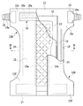
本実施形態によるテープ型使いすておむつの使用状態における外観を図1に示し、その内側の肌当接面側を表にして展開した状態の外観を図2に示し、これをさらに分解した状態の外観を図3に示し、図2中のIV−IV矢視に沿った断面構造を模式的に図4に示す。 FIG. 1 shows the appearance of the tape-type disposable diaper according to the present embodiment in use, and FIG. 2 shows the appearance of the tape-type disposable diaper in a state in which the skin contact surface side of the inside of the diaper is unfolded. 3 is shown in FIG. 3, and the cross-sectional structure taken along the line IV-IV in FIG. 2 is schematically shown in FIG.
すなわち、本実施形態におけるテープ型おむつ10は、液不透過性のカバーシート11と、バックシート12と、吸収体13と、液透過性のトップシート14と、左右一対のサイドシート15とを有する。トップシート14が重ね合わされるバックシート12は、トップシート14とほぼ同じ寸法形状を有し、良好な手触りを得るために薄い不織布にて形成されたカバーシート11に接合される。吸収体13は、バックシート12と、このバックシート12に重ね合わされるトップシート14との間に配され、バックシート12とトップシート14とが直接接するこれらの外周縁部は相互に一体的に接合される。液不透過性のサイドシート15の外側部分(図2中、左右両側)は、カバーシート11の左右両側に重ね合わされ、バックシート12およびトップシート14の左右両側縁部と、カバーシート11とに対してそれぞれ一体的に接合される。カバーシート11およびサイドシート15は、バックシート12およびトップシート14の左右、すなわち幅方向両側縁から外側へ延出する前後一対のサイドフラップ部10f,10rを有する。これらサイドフラップ部10f,10rの間の股下領域10Cには、着用者に脚周り開口部10Lとなる一対の切欠き部10Nが形成されている。
That is, the tape-
本実施形態においては、トップシート14の左右両側に覆い重なる左右一対のサイドシート15の内側部分(図2中、中央側)がトップシート14に対して非接合状態となっている。この内側部分に立体ギャザー15Gを形成するため、サイドシート15の内側端縁部に糸ゴム15aが伸張状態で接合されている。
In the present embodiment, the inside portions (center side in FIG. 2) of the pair of left and
後身頃領域10R側のサイドフラップ部10rの幅方向両側縁部には、着用時に前身頃領域F側のサイドフラップ部10fに重ね合わせてこれらをつなぐ左右一対のファスニングテープ16の基端部が接合されている。ファスニングテープ16を介して後身頃領域10R側のサイドフラップ部10rを前身頃領域10F側のサイドフラップ部10fに重ね合わせることにより、ウエスト周り開口部10Wと脚周り開口部10Lとが形成される。このファスニングテープ16は、その幅方向に沿って伸縮性を持たせた伸縮シートで構成され、その先端部分に面ファスナー16aが取り付けられている。面ファスナー16aは、前身頃領域10F側のカバーシート11に接合された面ファスナーシート17に対して繰り返し剥離可能に接合可能である。従って、弾性力を伴ってファスニングテープ16を引き延ばしてその面ファスナー16aの部分を前身頃領域10Fの面ファスナーシート17に接合することにより、着用者のウエスト周りに対して常に適切な締め付け力を与えることができる。
The base end portions of a pair of left and
また、このテープ型おむつ10の後身頃領域10R側の左右のサイドシート15には、トップシート14を跨ぐように配される横に細長いウエスト周り弾性シート18が伸長状態で接合されている。本実施形態におけるウエスト周り弾性シート18は、ベースシート18aと、このベースシート18aに伸長状態で相互に平行に接合される複数本の糸ゴム18bと、これら糸ゴム18bを覆うようにベースシート18aに接合される肌触りの良好なアッパーシート18cとで構成される。このウエスト周り弾性シート18はウエスト周り開口部10Wに沿って配設され、図示しないウエストギャザーを形成して着用者のウエスト周りのフィット性を良好にする機能を有する。同様に、吸収体13の両側縁の外側の長手方向に沿った股下領域10Cから前身頃領域10F側および後身頃領域10R側にかけて脚周り弾性部材19が配されている。本実施形態では糸ゴムにて形成した脚周り弾性部材19は、カバーシート11とサイドシート15との間に伸長状態で固定され、レッグギャザー19Gを形成して着用者の脚周りのフィット性を良好にする機能を有する。
Further, on the left and
従って、このテープ型おむつ10は、その着用時に前身頃領域10Fと後身頃領域10Rとで着用者のウエストの部分を取り囲むウエスト周り開口部10Wが形成される。同様に、前身頃領域10Fおよび後身頃領域10Rと、これらの下端部をつなぐ股下領域10Cとで着用者の両脚の太股部分を取り囲む左右一対の脚周り開口部10Lが形成される。
Therefore, the tape-
次に、本実施形態における吸収体13の部分の詳細な構造を説明する。
Next, a detailed structure of the
バックシート12との間に吸収体13を包むトップシート14の平面形状を図5に示し、その表面の一部を抽出拡大して図6に示し、図5中のVII−VII矢視およびVIII−VIII矢視に沿った断面形状を図7および図8にそれぞれ示す。
FIG. 5 shows a planar shape of the
本実施形態における吸収体13は、主にパルプとSAPとで構成される吸収性本体13aと、この吸収性本体13aを包むティシュペーパーなどのコアラップ13bとで構成される。しかしながら、コアラップ13bを必要としない、すなわち吸収性本体13aのみで吸収体13を構成することも可能である。この吸収体13は、おむつ10の前身頃領域10Fから股下領域10Cを通って後身頃領域10Rまで達するように、これらに対応した前身頃部分と股下部分と後身頃部分とを有する。吸収体13の股下部分には、両脚の太股部分を取り囲む左右一対の脚周り開口部10Lに合わせて、円弧状をなす一対の切欠き部13Aが形成され、股下部分の幅が前身頃部分および後身頃部分の幅に比べて狭くなっている。
The
なお、この切欠き部13Aを吸収体13に形成することは必須ではない。また、吸収体13の輪郭形状も本実施形態のような細長い形状以外に、楕円形や円形または正方形など、様々な形状を採用することができる。さらに、着用対象者やその用途などに応じて図5中、上下方向となる長手方向と、これに直交する図5中、左右方向となる幅方向との比率を任意に変更することが可能である。
In addition, it is not essential to form the
図5および図6に示されるように、吸収体13は、トップシート14と共にその表面からバックシート12に向かってエンボス加工を規則的に施したエンボスパターン形成領域、すなわち凹部形成領域ZRを有する。この凹部形成領域ZRには、エンボス加工による複数の凹部20a〜20cの配列によって、全体として、遠視的に斜め格子状のパターンとなるエンボスパターンが形成される。具体的には、格子の交点に位置する第3の凹部20cと、これら第3の凹部20cの間にそれぞれ位置し、第1の方向D1に沿って延在する第1の凹部20aおよび第1の方向D1と異なる第2の方向D2に沿って延在する第2の凹部20bとを具えている。本実施形態では、第1の方向D1が吸収体13の幅方向に対して45度傾斜し、第2の方向D2は吸収体13の幅方向に対して第1の方向D1とは逆方向に45度傾斜し、図5において左右対称のエンボスパターンとしているが、これらに限定されない。第1および第2の方向D1,D2は、吸収体13の幅方向に対して10度以上80度未満であることが有効であり、好ましくは30度以上45度以下である。第3の凹部20cは、第1の凹部20aおよび第2の凹部20bに対して不連続であり、その周囲はエンボス加工が施されない凹部非形成領域、すなわち未変形領域ZUにて囲まれた状態となっている。
As shown in FIG. 5 and FIG. 6, the
本実施形態における斜め格子状のエンボスパターンは、第1の凹部20aと第3の凹部20cとからなる第1の凹部列L1と、第2の凹部20bと第3の凹部20cとからなる第2の凹部列L2とで形成される。第1の凹部20aと第3の凹部20cとを第1の方向D1に沿って交互に配列した第1の凹部列L1は、第2の方向D2に沿って一定の間隔S2で配列している。また、第2の凹部20bと第3の凹部20cとを第2の方向D2に沿って交互に配列した第2の凹部列L2は、第1の方向D1に沿って一定の間隔S1で配列している。本実施形態では、第1の方向D1に沿った第2の凹部列L2の間隔S1および第2の方向D2に沿った第1の凹部列L1の間隔S2をそれぞれ27.0mmに設定しているが、これらの間隔S1,S2は、55.0mm以下であることが好ましい。しかしながら、間隔S1,S2を吸収体13の全域に亙って同じ値に設定する必然性はなく、これらを吸収体13の各部分によって異なる値に設定してもよい。また、格子の交点領域に第3の凹部20cを形成せず、ここを未変形領域ZUのままにしておくことも可能である。
The oblique lattice-shaped embossing pattern in the present embodiment has a first recess row L1 including a
なお、第1の凹部20a,第2の凹部20b,第3の凹部20cは、トップシート14と、コアラップ19および吸収体13とを共に一体的に圧縮して形成される。また、図5に示されるように、エンボスパターンは、吸収体13の周縁部には形成されておらず、従って凹部形成領域ZRは、このエンボスパターンが形成されない凹部非形成領域ZNによって取り囲まれた状態となっている。この凹部非形成領域ZNの存在により、エンボスパターンを構成する第1の凹部20a,第2の凹部20b,第3の凹部20cを伝って、尿などの液体が吸収体13の周縁部から漏れることを抑制することができる。なお、図5には便宜的に凹部形成領域ZRと凹部非形成領域ZNとの境界を二点鎖線で示してある。
The
そして、図5および図6から理解されるように、格子パターンを形成する格子のひとつのマス(マス目)は次の構成である。四辺の主要部は、各第1の凹部20a,第2の凹部20bで形成され、四隅は第3の凹部20cで形成される。ここで、第1の凹部20a,第2の凹部20bの長さUは、先の間隔S1,S2よりも短い。図5に示されるように、第1の凹部20aと第2の凹部20bとは重なり合わない。
As can be understood from FIGS. 5 and 6, one grid (grid) of the grid forming the grid pattern has the following configuration. The main parts of the four sides are formed by the
図6中、凹部20a〜20cの周囲をそれぞれ取り囲む二点鎖線で示す領域は、凹部準形成領域ZSである。すなわち、凹部20a〜20cをエンボス加工によって形成すると、トップシート14および吸収体13とが強く圧縮され、凹部20a〜20cの周囲のトップシート14および吸収体13がこれに引き寄せられて押し縮められることになる。このように、エンボス型によって強く圧縮された第1の凹部20a,第2の凹部21bおよび第3の凹部20cに対し、これらの周囲の弱く圧縮される領域を本明細書では凹部準形成領域ZSと呼称する。従って、吸収体13がエンボス加工によってエンボス加工前の状態から実質的に変形するのは、第1の凹部20a,第2の凹部20b,第3の凹部20cに加え、これらの周囲の凹部準形成領域ZSとなる。これら凹部20a〜20cおよび凹部準形成領域ZS以外はエンボス加工によって圧縮されないので、未変形領域ZUとなる。すなわち、格子の交点領域に位置する第3の凹部20cと第1の凹部20aおよび第2の凹部20bとの間の領域および格子で囲まれた領域は、未変形領域ZUであり、尿などの液体を保持する吸収体13本来の機能を達成する部分である。
In FIG. 6, the regions indicated by the alternate long and two short dashes lines surrounding the
図5および図6に示されるように、本実施形態における凹部非形成領域ZNおよび未変形領域ZUは、吸収体13の厚み(高さ)がエンボス加工前後でほぼ同じである。一方、凹部形成領域ZRの第1の凹部20aおよび第2の凹部20bと第3の凹部20cは、エンボス加工によって吸収体13が圧縮された状態となっており、未変形領域ZUよりも吸収体13の厚みが薄くなっている。凹部準形成領域ZSは、この凹部形成領域ZRと未変形領域ZUとをつなぎ、吸収体13の厚みが漸次薄く変化する部分である。
As shown in FIG. 5 and FIG. 6, the thickness (height) of the
次に、各凹部20a〜20cのより詳細な形状について具体的に説明する。
Next, more detailed shapes of the
図6〜図8に示されるように、第1の凹部20a,第2の凹部20bは、これらの輪郭を形成する浅凹部201と、各浅凹部201内に間欠的に配され、浅凹部201よりもさらに深く凹んだ円形の深凹部202とで構成されている。細長い浅凹部201は、図7に示されるように、第1の方向D1または第2の方向D2に対向する2つの凹部準形成領域ZSの間隔SZよりも短い長さUとほぼ一定の幅Vとを持つ細長い長円形状を有している。浅凹部201の幅Vよりも小径の深凹部202は、浅凹部201の長手方向に沿って所定間隔で浅凹部201の対向する側壁部分に交互に内接状態で配されている。深凹部202は、浅凹部201よりもバックシート12側に近づくように深くくぼんでいる。
As shown in FIGS. 6 to 8, the
図8に示されるように、未変形領域ZUにあるトップシート14の表面からバックシート12側に向けて最も遠い(深い)所に深凹部202が位置し、未変形領域ZUにあるトップシート14の表面と深凹部202との間に浅凹部201が位置する。浅凹部201の底面から深凹部202の底面までの深さ、すなわち未変形領域ZUにあるトップシート14の表面から深凹部202の底面までの深さ(以下、単に深凹部202の深さと記述する)Q1と、未変形領域ZUにあるトップシート14の表面から浅凹部201の底面までの深さ(以下、単に浅凹部201の深さと記述する)Q2との差Q3は、深凹部202の深さQ1の約3.5〜15%程度である。また、未変形領域ZUにおけるトップシート14からバックシート12までの距離、すなわち吸収体13の厚みをQ4とすると、深凹部202の深さQ1は、この厚みQ4の42.5%〜97.5%程度である。同様に、浅凹部201の深さQ2は、厚みQ4の37.5%〜95.0%程度である。このように、本実施形態における第1の凹部20a,第2の凹部20bは、吸収体13をかなり深くまで圧縮して形成されている。そして、2段階の深さを有する形状となっている。
As shown in FIG. 8, the
一方、図8に示されるように、未変形領域ZUにあるトップシート14の表面から格子の交点領域に位置する第3の凹部20cの底面までの深さ(以下、第3の凹部20cの深さと記述する)は、浅凹部201の深さQ2と同じになるように設定されている。
On the other hand, as shown in FIG. 8, the depth from the surface of the
より具体的には、吸収体13の未変形領域ZUの厚みQ4は8.0mmであるが、これは5.0mm〜20.0mmの範囲にあることが好ましい。図8に示されるように、深凹部202の深さQ1は7.8mmであるが、3.0mm〜8.0mmの範囲にあることが好ましい。そして、浅凹部201の深さQ2は7.5mm、浅凹部201の深さQ2と深凹部202の深さQ1との差Q3は、0.1mm〜0.5mmの範囲にあることが好ましい。
More specifically, the thickness Q4 of the undeformed region ZU of the
第1の凹部20a,第2の凹部20bおよび第3の凹部20cを形成するエンボス加工は、トップシート14と吸収体13との間に接着剤を介在させ、トップシート14表面からトップシート14と吸収体13とを共に圧縮するものである。第1の凹部20a,第2の凹部20b、第3の凹部20cは、エンボスロールに形成された所定の型によって、トップシート14の表面からトップシート14と吸収体13とを共に圧縮して形成されたものである。
In the embossing process for forming the
そして、第1の凹部20a,第2の凹部20bにおいては、深凹部202は、小さな円であり、その面積は小さい。従って、エンボスロールによる押圧において、深凹部202に圧力が集中し、吸収体13とトップシート14は強く圧縮される。この圧縮の際に、吸収体13のパルプ繊維とトップシート14の繊維とがしっかりと絡み合い、両者が一体となった状態で接合される。次に、浅凹部201においても圧縮の際に同じ押圧力が加わるが、面積が広い分、圧力は深凹部202ほど集中しない。このため、吸収体13とトップシート14との接合は深凹部202に比べるとわずかに弱いが、その凹部形状を形成するには十分である。このように、深凹部202において吸収体13が強く圧縮されているとともに、吸収体13とトップシート14とがしっかりと接合することにより、第1の凹部20a,第2の凹部20bの形状が維持される。例えば、このおむつ10の着用者が着座するなどして、吸収体13表面に着用者の体重による圧力が加わった際にも、この第1の凹部20a,第2の凹部20bはへたることなく、その形状が維持される。そして、脚の様々な動きによって、おむつ10が強く引っ張られたりしても、トップシート14と吸収体13とがしっかりと接合しているため、第1の凹部20a,第2の凹部20bはその形状を維持することができる。
Then, in the
ここで、浅凹部201と深凹部202の二段階構造とするのではなく、第1の凹部20a,第2の凹部20b全体に強い圧縮力を加えて形成することも考えられる。すなわち、エンボス加工において、浅凹部201に合わせた略楕円状の突起の内部にさらに、深凹部202に合わせた丸い突起を突出させた型を用いるのではなく、表面が平らな略楕円状の突起のみの型を用いて圧縮することも考えられる。しかしながら、そのような型では圧力が集中する箇所が作られていないので、全体的に強く圧力を加えないと、トップシート14と吸収体13との繊維が強く絡み合った状態で接合する箇所を作り出せない。結果として、必要な押圧力は大変強くなり、トップシート14が破れてしまう場合がある。また、全体に弱い押圧力での圧縮では、着用者の体重や様々な動きに耐えられる第1の凹部20a,第2の凹部20bを形成することが難しい。本実施形態では、エンボス加工の型において深凹部202に対応する突起を設けて、部分的に強く圧縮することにより、トップシート14と吸収体13とがしっかりと接合する箇所を作るとともに、製造時にトップシート14が破れるなどの不良発生を防ぐことができる。
Here, instead of using the two-step structure of the
さらに、格子の交点領域に配される第3の凹部20cは、上述したように、エンボスロールによって吸収体13が浅凹部201と同じ程度押圧されて圧縮されることで形成される。この押圧の強さはトップシート14が破れることなく、トップシート14と吸収体13との一体的な接合を実現する程度の強さである。
Further, as described above, the
図7,図8に示されるように、吸収体13において、深凹部202の底面部分は、吸収体13の密度が最も高い高密度部13Hであり、先の未変形領域ZUは、吸収体13の密度が最も低い低密度部13Lである。また、浅凹部201の底面部分および第3の凹部20cの底面部分は、密度が高密度部13Hと低密度部13Lの中間の中密度部13Mである。さらに凹部準形成領域ZSは、未変形領域ZUに向けて密度がしだいに低くなっていく密度変化部13Vとなる。
As shown in FIGS. 7 and 8, in the
前述したように、吸収体13は主にSAPとパルプとからなるものであり、密度は主にパルプ繊維密度が関与している。従って、高密度部13Hはパルプが圧縮され、パルプ間の隙間が少ない状態である一方、低密度部13Lは、パルプ間の隙間が高密度部13Hに比べて多い状態である。
As described above, the
加えて、凹部20a〜20cは、合成樹脂であるトップシート14と主成分がパルプの吸収体13とを共に圧縮接合して形成されているので、凹部20a〜20cの底面から高密度部13Hへと尿などの液体があまり吸収されない傾向を持つ。従って、凹部20a〜29cに流れ込む液体は、凹部20a〜20cの側壁を通って密度変化部13Vへと吸収され、さらに未変形領域ZUの低密度部13Lへと流動する。
In addition, since the
本実施形態では、第1および第2の凹部列L1,L2を形成する上で、凹部20a〜20cを連続させることなく、間欠的に凹部20a〜20cを形成している。特に、この斜め格子の交点領域に第3の凹部20cを設け、これを取り囲む第1の凹部20a,第2の凹部20bを第3の凹部20cから離して位置させている。第3の凹部20cを取り囲むこのような隙間、すなわち未変形領域ZUを形成する理由について以下に説明する。
In the present embodiment, when forming the first and second recess row L1 and L2, the
上述したように、斜め格子の第1および第2の凹部列L1,L2は、各凹部20a〜20cに対して相補的形状のエンボスパターンを表面に形成したエンボスロールを回転させながら押し当てることにより形成される。図5に示されるように、エンボスロールを回転させながら吸収体13をその長手方向に送り込むと、吸収体13の搬送方向(図5中、上方向)に対して直交する吸収体13の幅方向に並ぶ第1の凹部20aおよび第2の凹部20bの部分が同時にエンボスロールに押圧される。本実施形態では、エンボスロールの円周長は、切断されるべきバックシート12およびトップシート14の長さに対応するように、エンボスロールの径が設定されているが、これに限らない。
As described above, the first and second rows L1 and L2 of the oblique lattice are formed by pressing the respective embossing patterns having complementary embossing patterns on the surface thereof while rotating the embossing rolls. It is formed. As shown in FIG. 5, when the
なお、本実施形態では吸収体13を一定間隔で配したバックシート12およびトップシート14の連続体の搬送方向に対し、エンボスロールの回転軸線を直交させている。上述したように、トップシート14と吸収体13とを共にエンボスロールで圧縮した後、カバーシート11やサイドシート15などを重ね合わせて接合し、所定の寸法のおむつ10へと切断される。
In this embodiment, the rotation axis of the embossing roll is orthogonal to the conveying direction of the continuous body of the
第1の凹部20aは、吸収体13の搬送方向に対して右45度傾斜し、第2の凹部20bは左45度傾斜することとなる。このため、エンボスロールに対して吸収体13への送り込みが進むにつれて、格子の交点に向かって吸収体13の幅方向に隣接する第1の凹部20aと第2の凹部20bと間の距離が短くなって行く。
The
ここで、凹部20a〜20cを形成するエンボスロールの押圧の際、トップシート14は凹部20a〜20c内に引き込まれることになる。特に、第1の凹部20aと第2の凹部20bは、吸収体13の幅方向に隣接して配された状態となるため、これらを形成する上で同時に左右からトップシート14が引き込まれることになる。つまり、吸収体13の幅方向(図6中、左右方向)の引き込み力が隣接する第1の凹部20aと第2の凹部20bとの間で左右同時にトップシート14に加わることになる。隣接する第1の凹部21aと第2の凹部21bとの距離が短くなるほど、すなわち格子の交点に近づくほどこれらの間のトップシート14に強い引っ張り力が作用する。
Here, when the embossing roll forming the
例えば、同じ大きさの格子パターンを形成する際に第3の凹部20cを省略して第1の凹部20aおよび第2の凹部20bを格子の交点直近にまで延在させた場合、つぎのような問題が生ずる。すなわち、格子の交点近傍においては、吸収体13自体の密度が高く、硬い状態であるところに加え、近接する左右の凹部20a,20bのエンボス加工の際に発生する引き込み力によって、トップシート14が強く吸収体13に押し付けられた状態となる。このため、格子の交点近傍においては、吸収体13に含まれるSAPがトップシート14に強く当たり、ざらざらとした手触りとなる。これは、着用者の肌に対して刺激となるため、好ましくない。
For example, when the
従って、本実施形態では、吸収体13の幅方向に隣接する第1の凹部20aと第2の凹部20bとの距離をある程度以上に保ち、それ以上、トップシート14が強く引っ張られる状態としないようにする。すなわち、トップシート14が塑性変形を伴う伸びではなく、弾性変形を伴う伸びに留まるように、余裕を持たせた状態で吸収体13の圧縮および吸収体13とトップシート14との接合を行う。これにより、SAPによるざらざらとした手触りおよび格子の交点領域が硬くなることを抑制する。
Therefore, in the present embodiment, the distance between the first
このような状態を満たす吸収体13の幅方向に沿った第1の凹部20aと第2の凹部20bとの最短距離を以下、便宜的にTと表記する。吸収体13の幅方向に沿った第1の凹部20aと第2の凹部20bとの最短距離をT以上にすることにより、トップシート14には強い引っ張り力が掛からない状態で吸収体13に固定されることとなり、硬い手触りを回避することができる。上述したトップシート14の過大な引っ張り力についての問題は、吸収体13の長手方向に関しては発生しないけれども、吸収体13が硬くなるという問題については解消できない。従って、吸収体13の長手方向に沿った第1の凹部20aと第2の凹部20bとの最短距離もT以上とすることが有効である。
Hereinafter, the shortest distance between the first
言い換えると、エンボスパターンの設定時に、第1および第2の凹部列L1,L2によって仕切られる格子の対角線と平行な方向において、隣接する第1および第2の凹部20a,20bの距離がT以上となるように、凹部20a,20bの長さUが設定される。
In other words, when the emboss pattern is set, the distance between the adjacent first and
一例として、吸収体13の厚みが8mm、第3の凹部の深さQ2が6mmの場合、上述したTは7mm程度である。この値は、吸収体13におけるSAPの量とパルプ繊維量との関係や、トップシート14の厚みによっても変化する。本発明において重要な点は、斜め格子状など斜めの成分を有するエンボスパターンを用いる際に、隣接する凹部間の間隔が狭くなる部分にはエンボスパターンを形成しないということである。
As an example, when the thickness of the
一方で、格子の交点自体は、近接して左右両方から同時に押圧される場所でないため、トップシート14が強く引っ張られることがない。トップシート14に作用する張力を考慮して凹部20a〜20cが形成されない未変形領域ZUを広く取りすぎると、第1および第2の凹部列L1,L2が列として識別されなくなり、格子パターンとして認識されない可能性がある。また、あまりに第1の凹部20aおよび第2の凹部20bと第3の凹部20cとの間隔、つまり未変形領域ZUが広いと、吸収体13が体の動きに追従して斜めに折れ曲がりやすいという作用を発揮させにくくなる。従って、トップシート14に作用する張力に関して影響のない格子の交点領域に第3の凹部20cを形成し、格子としての認識性を高めてその視覚的効果をより向上させることができる。また、格子の交点領域を硬質化させることなく、着用者の体の動きに吸収体13が追従し、折れ曲がりやすくすることができる。
On the other hand, since the intersection of the lattice itself is not a place that is closely approached and pressed from both the left and right simultaneously, the
このように、本実施形態では、隣接する凹部21間の最短距離がT未満とならないようにする。つまり、凹部21を距離T以上離して配置したエンボスパターン、すなわち、格子の交点近傍26はエンボス加工しないエンボスパターンとすることにより、肌当接面の肌触りが硬くなることを防ぐ。そして、格子の交点領域は吸収体13の未変形領域ZUと同様にふんわりとした状態であるので、斜め格子状のエンボスパターンを用いても、格子の交点領域が硬く尖った手触りとならず、着用者にふんわりとした肌触りを与えることができる。
As described above, in the present embodiment, the shortest distance between the adjacent concave portions 21 is set not to be less than T. That is, the embossed pattern in which the concave portions 21 are arranged at a distance T or more, that is, the vicinity 26 of the intersection of the lattice is an embossed pattern that is not embossed, so that the skin contact surface is prevented from becoming hard to the touch. Since the intersection area of the lattice is fluffy like the undeformed area Z U of the
また、第1の凹部列L1と第2の凹部列L2の交点には、第3の凹部20cを設けることにより、格子の交点(マスの頂点)を視覚的に明確化させ、美観性、デザイン性を向上させる。また、この斜めに伸びる凹部列L1,L2によって、製造不良によるしわや、不規則に並んだヨレ等と混同されないようにすることができる。また、体の動きに追従した吸収体13の斜め方向にも変形しやすくなる。しかしながら、第3の凹部20cを省略することも可能であり、この場合には、第1の凹部20aおよび第2の凹部20bを格子の交点領域により近接するように、これらの長さを増大させることが好ましい。
Further, by providing a
本実施形態における第1の凹部20a,第2の凹部20bの長手方向の長さUは19.0mmであるが、第2の凹部列L2の間隔S1および第1の凹部列L1の間隔S2の55%から85%であることが好ましい。また、第1の凹部20a,第2の凹部20bの幅Vは、3.0mmであるが、2.0mm以上4.0mm以下であることが好ましい。また、第1の方向D1または第2の方向D2に沿った第3の凹部20cの幅V1は、第1の凹部20a,第2の凹部20bの幅Vと同じか、それよりも狭い。本実施形態では幅V1を2.0mmに設定しているが、1.0mm以上4.0mm以下であることが好ましい。一方、第1および第2の凹部20a,20bと、第3の凹部20cとの間の隙間、すなわち未変形領域ZUの長さは、4.4mmであるが、2.0mm以上6.0mm以下であることが好ましい。
In the present embodiment, the length U of the first
各凹部20a〜20cをこのような深さおよび間隔で形成することにより、体重が加わっても、その溝を維持することができるとともに、おむつの股下部の肌当接面において、柔らかい肌触りを維持することができる。従って、斜め格子状のエンボスパターンにより、脚の様々な動きに対しておむつがよれるなど変形を抑制できるとともに、その肌触りを柔らかいものとして、肌への刺激を極力抑えることができる。
By forming each of the
なお、本実施形態において、第1の凹部20a,第2の凹部20bは、細長い略楕円形の浅凹部201によってその外形が確定されるものとしたが、本発明はこれに限らず、斜め格子状の圧縮列を複数のドットや平行四辺形などの凹部を間欠的に配置して形成してもよい。すなわち、本実施形態において、凹部を形成しない交点近傍26を所定の大きさだけ設けることが重要であり、格子の各辺を構成する第1の凹部20a,第2の凹部20bで画定している部分の凹部の形状はこの実施形態に限るものではない。上述の複数のドット等を配列しても同様の効果を得ることができる。この場合においても、前記格子のマスの対角線に平行な方向における隣接する凹部間の距離はT以上となるように凹部は配置されることとなる。
In the present embodiment, the outer shapes of the
また、本実施形態において、一つの第1の凹部20a,第2の凹部20bではなく、長手方向の長さを短くした2つ以上の第1の凹部20a,第2の凹部20bによって、マスの一辺を形成するようにしてもよい。また、浅凹部201内の深凹部202の配置は、互い違いとなるように、幅方向外側に振り分けているが、本発明はこれに限らず、中央に一列に並べる構成などいかなるものであってもよい。また、深凹部202の形状は本実施形態に示した形状に限らず、四角形、楕円形、三角形など様々な形状を取り得る。
In addition, in the present embodiment, the mass of the mass is not increased by the
また、本実施形態において、第3の凹部は四角形の糸巻き形状としたが、本発明はこれに限らず、樽形の四角形や円形などでもよい。すなわち、格子パターンにおける格子の交点と認識させる上で適当な形であれば、いかなるものであってもよい。 Further, in the present embodiment, the third recess has a quadrangular bobbin shape, but the present invention is not limited to this and may have a barrel-shaped quadrangle or a circle. That is, any shape may be used as long as it is suitable for recognizing the intersection of the grid in the grid pattern.
このように、本発明はその特許請求の範囲に記載された事項のみから解釈されるべきものであり、上述した実施形態においても、本発明の概念に包含されるあらゆる変更や修正が記載した事項以外に可能である。つまり、上述した実施形態におけるすべての事項は、本発明を限定するためのものではなく、本発明とは直接的に関係のない構成を含め、その用途や目的などに応じて任意に変更し得るものである。 As described above, the present invention should be construed only from the matters described in the scope of the claims, and in the above-described embodiment, all the changes and modifications included in the concept of the present invention are described. Other than that, it is possible. That is, all the matters in the above-described embodiment are not intended to limit the present invention, and may be arbitrarily changed according to the use and purpose thereof, including the configuration not directly related to the present invention. It is a thing.
10 テープ型使い捨ておむつ(おむつ)
10C 股下領域
10F 前身頃領域
10L 脚周り開口部
10N 切欠き部
10R 後身頃領域
10W ウエスト周り開口部
10f,10r サイドフラップ部
11 カバーシート
12 バックシート
13 吸収体
13a 吸収性本体
13b コアラップ
13A 切欠き部
13H 高密度部
13M 中密度部
13L 低密度部
13V 密度変化部
14 トップシート
15 サイドシート
15G 立体ギャザー
15a 糸ゴム
16 ファスニングテープ
16a 面ファスナー
17 面ファスナーシート
18 ウエスト周り弾性シート
18a ベースシート
18b 糸ゴム
18c アッパーシート
19 脚周り弾性部材
19G レッグギャザー
20a 第1の凹部
20b 第2の凹部
20c 第3の凹部
201 浅凹部
202 深凹部
L1 第1の凹部列
L2 第2の凹部列
D1 第1の方向
D2 第2の方向
S1 第2の凹部列の間隔
S2 第1の凹部列の間隔
ZR 凹部形成領域
ZN 凹部非形成領域
ZS 凹部準形成領域
ZU 未変形領域
U 浅凹部の長さ
V 浅凹部の幅
V1 第3の凹部の幅
Q1 未変形領域にあるトップシートの表面から深凹部の底面までの深さ
Q2 未変形領域にあるトップシートの表面から浅凹部の底面までの深さ
Q3 浅凹部の底面から深凹部の底面までの深さ
Q4 未変形領域におけるトップシートからバックシートまでの距離(吸収体の厚み)
10 tape type disposable diapers (diapers)
10C Inseam area 10F Front body area 10L Leg opening 10N Notch 10R Rear body area 10W Waist opening 10f, 10r Side flap 11 Cover sheet 12 Backsheet 13 Absorber 13a Absorbent body 13b Core wrap 13A Notch 13H High density part 13M Medium density part 13L Low density part 13V Density change part 14 Topsheet 15 Sidesheet 15G Three-dimensional gather 15a Thread rubber 16 Fastening tape 16a Surface fastener 17 Surface fastener sheet 18 Waist elastic sheet 18a Base sheet 18b Thread rubber 18c Upper sheet 19 Leg elastic member 19G Leg gather 20a First concave portion 20b Second concave portion 20c Third concave portion 201 Shallow concave portion 202 Deep concave portion L1 First concave row L2 Second concave row D1 First direction D2 Second Direction of 2 S1 Distance between second concave rows S2 Distance between first concave rows Z R concave forming area Z N concave non-forming area Z S concave semi-forming area Z U undeformed area U shallow concave length V shallow concave Width V1 Width of the third recess Q1 Depth from the surface of the top sheet in the undeformed region to the bottom of the deep recess Q2 Depth from the surface of the top sheet in the undeformed region to the bottom of the shallow recess Q3 Shallow recess From the bottom surface of the bottom to the bottom of the deep recess Q4 Distance from the top sheet to the back sheet in the undeformed region (thickness of the absorber)
Claims (4)
を有するおむつであって、
前記トップシートと対向する前記吸収体の表面に形成されて第1の方向に沿って延在する第1の凹部と、
前記トップシートと対向する前記吸収体の表面に形成されて前記第1の方向と異なる第2の方向に沿って延在する第2の凹部と
を具え、前記第1の凹部および前記第2の凹部は、前記吸収体の表面から前記第1の凹部および第2の凹部の底面に向かって圧縮され、前記吸収体の表面から前記第1の凹部および第2の凹部の底面までの深さQ2が浅い第1の領域と、前記吸収体の表面から前記第1の凹部および第2の凹部の底面に向かって圧縮され、この第1の領域よりも前記吸収体の表面から前記第1の凹部および前記第2の凹部の底面までの深さQ1が深い第2の領域とをそれぞれ有し、前記Q2は3.0mm〜8.0mmであり、前記Q1と前記Q2との差は0.1mm〜0.5mmの範囲にあり、
前記吸収体は前記第1の領域および第2の領域の下部表面と前記バックシートとの間に存在し、
前記第1の方向と前記第2の方向との交差領域において前記第1の凹部と前記第2の凹部とは重なり合っておらず、前記交差領域に形成される第3の凹部をさらに具え、
前記吸収体と一体的に前記トップシートにも前記第1の凹部、前記第2の凹部および前記第3の凹部が形成され,
前記吸収体は、前記第3の凹部とこれに隣接する前記第1の凹部および前記第2の凹部との間に未変形領域を有することを特徴とするおむつ。 A diaper having a liquid-permeable topsheet, a liquid-impermeable backsheet, and an absorber containing a highly liquid-absorbent resin, which is arranged between the topsheet and the backsheet,
A first concave portion formed on the surface of the absorber facing the top sheet and extending along a first direction;
Comprising a second recess extending along the second direction are formed on a surface different from the first direction of the absorbent body facing the top sheet, said first recess and said second The recess is compressed from the surface of the absorber toward the bottoms of the first recess and the second recess, and the depth Q2 from the surface of the absorber to the bottoms of the first recess and the second recess. Is compressed toward the bottom surface of the first recess and the second recess from the surface of the absorber and the shallow first region, and the first recess from the surface of the absorber from the first region. And a second region in which the depth Q1 to the bottom surface of the second recess is deep, the Q2 is 3.0 mm to 8.0 mm, and the difference between the Q1 and the Q2 is 0.1 mm. ~ 0.5 mm range,
The absorber is present between the lower surface of the first region and the second region and the backsheet,
Wherein not overlap the first direction and the second direction Oite the first recess and the second recess in the intersections of, further comprising a third recess formed in the intersection region ,
The first recess, the second recess, and the third recess are formed in the top sheet integrally with the absorber,
The said absorber has an undeformed area | region between the said 3rd recessed part and the said 1st recessed part and the said 2nd recessed part which adjoin this, The diaper characterized by the above-mentioned.
Applications Claiming Priority (4)
| Application Number | Priority Date | Filing Date | Title |
|---|---|---|---|
| JP2014205218 | 2014-10-03 | ||
| JP2014205218 | 2014-10-03 | ||
| JP2014225418 | 2014-11-05 | ||
| JP2014225418 | 2014-11-05 |
Publications (3)
| Publication Number | Publication Date |
|---|---|
| JP2016093482A JP2016093482A (en) | 2016-05-26 |
| JP2016093482A5 JP2016093482A5 (en) | 2018-02-01 |
| JP6695668B2 true JP6695668B2 (en) | 2020-05-20 |
Family
ID=56070546
Family Applications (1)
| Application Number | Title | Priority Date | Filing Date |
|---|---|---|---|
| JP2015188168A Active JP6695668B2 (en) | 2014-10-03 | 2015-09-25 | Absorbent article |
Country Status (1)
| Country | Link |
|---|---|
| JP (1) | JP6695668B2 (en) |
Families Citing this family (2)
| Publication number | Priority date | Publication date | Assignee | Title |
|---|---|---|---|---|
| JP6693301B2 (en) * | 2016-06-30 | 2020-05-13 | 王子ホールディングス株式会社 | Absorbent article |
| JP2019017863A (en) * | 2017-07-20 | 2019-02-07 | 王子ホールディングス株式会社 | Absorber and absorbent article using the same |
Family Cites Families (3)
| Publication number | Priority date | Publication date | Assignee | Title |
|---|---|---|---|---|
| JP5665338B2 (en) * | 2010-03-24 | 2015-02-04 | ユニ・チャーム株式会社 | Body fluid treatment article and method for producing the same |
| JP5812651B2 (en) * | 2011-03-31 | 2015-11-17 | ユニ・チャーム株式会社 | Disposable diapers |
| JP2014097132A (en) * | 2012-11-13 | 2014-05-29 | Uni Charm Corp | Absorbent article |
-
2015
- 2015-09-25 JP JP2015188168A patent/JP6695668B2/en active Active
Also Published As
| Publication number | Publication date |
|---|---|
| JP2016093482A (en) | 2016-05-26 |
Similar Documents
| Publication | Publication Date | Title |
|---|---|---|
| CN107072841B (en) | Absorbent article | |
| CN109640908B (en) | Absorbent article | |
| KR101971107B1 (en) | Absorbent Article | |
| WO2012133331A1 (en) | Disposable diaper | |
| CN106999308B (en) | Absorbent article | |
| JP6785231B2 (en) | Absorbent article | |
| JP6531378B2 (en) | Absorbent articles | |
| JP6695668B2 (en) | Absorbent article | |
| JP6365406B2 (en) | Absorbent articles | |
| TW201740892A (en) | Absorbent article | |
| JP2019069379A (en) | Absorbent article | |
| JP6939864B2 (en) | Absorbent article | |
| JP6310289B2 (en) | Absorbent articles | |
| CN109069326B (en) | Absorbent article | |
| JP6503877B2 (en) | Absorbent articles | |
| JP6413921B2 (en) | Absorbent articles | |
| JP6610733B2 (en) | Absorbent articles | |
| JP6617593B2 (en) | Absorbent articles | |
| JP2016214405A (en) | Absorbent article | |
| JP2015173766A (en) | absorbent article | |
| JP2013128668A (en) | Absorbent article |
Legal Events
| Date | Code | Title | Description |
|---|---|---|---|
| A521 | Request for written amendment filed |
Free format text: JAPANESE INTERMEDIATE CODE: A523 Effective date: 20171211 |
|
| A621 | Written request for application examination |
Free format text: JAPANESE INTERMEDIATE CODE: A621 Effective date: 20171211 |
|
| A131 | Notification of reasons for refusal |
Free format text: JAPANESE INTERMEDIATE CODE: A131 Effective date: 20180918 |
|
| A521 | Request for written amendment filed |
Free format text: JAPANESE INTERMEDIATE CODE: A523 Effective date: 20181016 |
|
| A02 | Decision of refusal |
Free format text: JAPANESE INTERMEDIATE CODE: A02 Effective date: 20190108 |
|
| A521 | Request for written amendment filed |
Free format text: JAPANESE INTERMEDIATE CODE: A523 Effective date: 20190408 |
|
| A911 | Transfer to examiner for re-examination before appeal (zenchi) |
Free format text: JAPANESE INTERMEDIATE CODE: A911 Effective date: 20190416 |
|
| A912 | Re-examination (zenchi) completed and case transferred to appeal board |
Free format text: JAPANESE INTERMEDIATE CODE: A912 Effective date: 20190524 |
|
| A521 | Request for written amendment filed |
Free format text: JAPANESE INTERMEDIATE CODE: A523 Effective date: 20191212 |
|
| A521 | Request for written amendment filed |
Free format text: JAPANESE INTERMEDIATE CODE: A523 Effective date: 20200226 |
|
| A61 | First payment of annual fees (during grant procedure) |
Free format text: JAPANESE INTERMEDIATE CODE: A61 Effective date: 20200422 |
|
| R150 | Certificate of patent or registration of utility model |
Ref document number: 6695668 Country of ref document: JP Free format text: JAPANESE INTERMEDIATE CODE: R150 |
|
| R250 | Receipt of annual fees |
Free format text: JAPANESE INTERMEDIATE CODE: R250 |
|
| R250 | Receipt of annual fees |
Free format text: JAPANESE INTERMEDIATE CODE: R250 |