JP6694639B1 - Lifting device and work table boat equipped with the lifting device - Google Patents
Lifting device and work table boat equipped with the lifting device Download PDFInfo
- Publication number
- JP6694639B1 JP6694639B1 JP2018236570A JP2018236570A JP6694639B1 JP 6694639 B1 JP6694639 B1 JP 6694639B1 JP 2018236570 A JP2018236570 A JP 2018236570A JP 2018236570 A JP2018236570 A JP 2018236570A JP 6694639 B1 JP6694639 B1 JP 6694639B1
- Authority
- JP
- Japan
- Prior art keywords
- leg
- engagement
- lifting device
- platform
- pin
- Prior art date
- Legal status (The legal status is an assumption and is not a legal conclusion. Google has not performed a legal analysis and makes no representation as to the accuracy of the status listed.)
- Active
Links
- 230000003028 elevating effect Effects 0.000 claims abstract description 27
- 238000013459 approach Methods 0.000 claims abstract description 5
- 238000009751 slip forming Methods 0.000 claims description 4
- 230000002093 peripheral effect Effects 0.000 claims 1
- 238000010586 diagram Methods 0.000 abstract description 2
- 230000000087 stabilizing effect Effects 0.000 abstract description 2
- 238000009434 installation Methods 0.000 description 6
- 230000001965 increasing effect Effects 0.000 description 5
- 238000003780 insertion Methods 0.000 description 4
- 230000037431 insertion Effects 0.000 description 4
- 238000012986 modification Methods 0.000 description 3
- 230000004048 modification Effects 0.000 description 3
- 238000005192 partition Methods 0.000 description 3
- 241000258937 Hemiptera Species 0.000 description 2
- 239000004677 Nylon Substances 0.000 description 2
- 230000001174 ascending effect Effects 0.000 description 2
- 239000012530 fluid Substances 0.000 description 2
- 230000005484 gravity Effects 0.000 description 2
- 238000000034 method Methods 0.000 description 2
- 229920001778 nylon Polymers 0.000 description 2
- 229910000831 Steel Inorganic materials 0.000 description 1
- 238000005299 abrasion Methods 0.000 description 1
- 238000004873 anchoring Methods 0.000 description 1
- 238000007667 floating Methods 0.000 description 1
- 238000010248 power generation Methods 0.000 description 1
- 238000007789 sealing Methods 0.000 description 1
- 239000010959 steel Substances 0.000 description 1
- XLYOFNOQVPJJNP-UHFFFAOYSA-N water Substances O XLYOFNOQVPJJNP-UHFFFAOYSA-N 0.000 description 1
Images


Abstract
【課題】ロック装置の係合ピンとレグの被係合部との間での係合が安定するとともに、レグの重量アップやコストアップを抑制できる昇降装置および該昇降装置を備える作業台船を提供する。【解決手段】プラットフォーム2を支持するレグ3に対して相対移動を可能にする昇降装置4であって、レグの対向する2面の係合面には、複数の係合凹部35がレグの長手方向に形成されており、昇降装置は、レグをロック固定するための係合ピン56を駆動して、係合ピンの係合凸面58を係合凹部の係合凹面36に係合させる一対のロック装置50と、一対のロック装置が互いに離れるかまたは近づくように、一対のロック装置のうちの一方を昇降させる昇降シリンダ装置60とを備え、係合凹部がレグの内側に向けて先細のテーパー形状をしているとともに、係合ピンが係合凹部に向けて先細のテーパー形状をしている。【選択図】図3PROBLEM TO BE SOLVED: To provide an elevating device capable of stabilizing engagement between an engagement pin of a locking device and an engaged part of a leg and suppressing an increase in weight and cost of the leg, and a work pontoon equipped with the elevating device. To do. A lifting device (4) that enables relative movement with respect to a leg (3) that supports a platform (2), and a plurality of engaging recesses (35) are formed on the engaging surfaces of two opposing surfaces of the leg. The elevator device drives the engagement pin 56 for locking and fixing the leg to engage the engagement convex surface 58 of the engagement pin with the engagement concave surface 36 of the engagement concave portion. A locking device 50 and a lifting cylinder device 60 that moves one of the pair of locking devices up and down so that the pair of locking devices move away from or approach each other are provided, and the engagement recess is tapered toward the inside of the leg. In addition to the shape, the engagement pin has a taper shape which is tapered toward the engagement recess. [Selection diagram] Fig. 3
Description
この発明は、昇降装置および該昇降装置を備える作業台船に関する。 The present invention relates to a lifting device and a work pontoon ship equipped with the lifting device.
例えば、特許文献1は、プラットフォームのガイド穴に挿通される複数の支持柱(以下、レグと言うが、スパッドと言われることもある。)と、レグに形成された貫通係合孔(被係合部として働く。)に差し込まれる可動側の係合ピンおよび固定側の係合ピンをそれぞれ駆動する一対のロック装置と、一対のロック装置を連結して支持する昇降シリンダ装置とを備える昇降装置を開示する。昇降装置は、レグをプラットフォームに対して下方向に相対移動させることにより、プラットフォームを海面よりも上方に持ち上げる。プラットフォームを波浪の影響を受けない海面よりも上方に配置することにより、プラットフォームが安定化する。 For example, in Patent Document 1, a plurality of support columns (hereinafter, also referred to as legs, but sometimes referred to as spuds) inserted into guide holes of the platform, and through engagement holes (engagement target) formed in the legs. And a pair of lock devices for driving the movable side engagement pin and the fixed side engagement pin, respectively, and a lifting cylinder device for connecting and supporting the pair of locking devices. Is disclosed. The lifting device lifts the platform above the sea surface by moving the leg in a downward direction relative to the platform. Placing the platform above the sea surface, which is not affected by the waves, stabilizes the platform.
固定側の係合ピンを貫通係合孔に差し込んで可動側の係合ピンを貫通係合孔から引き抜いた状態で昇降シリンダ装置の連結ロッドを突出させると、可動側のロック装置が上昇する。そして、さらに、可動側の係合ピンを貫通係合孔に差し込んで固定側の係合ピンを貫通係合孔から引き抜いた状態で昇降シリンダ装置の連結ロッドを引っ込めると、固定側のロック装置(プラットフォーム)が上昇する。昇降装置が当該動作を繰り返すことにより、プラットフォームが徐々に上昇する。 When the connecting rod of the elevating cylinder device is projected in a state in which the fixed side engagement pin is inserted into the through engagement hole and the movable side engagement pin is pulled out from the through engagement hole, the movable side lock device moves up. When the movable side engagement pin is further inserted into the through engagement hole and the fixed side engagement pin is pulled out from the through engagement hole, the connecting rod of the lifting cylinder device is retracted. Platform) will rise. The platform is gradually raised by the lifting device repeating the operation.
特許文献1では、貫通係合孔が円筒形状をしたレグの管壁を貫通するとともに、貫通係合孔の内径が係合ピンの外径よりも大きくて係合ピンと貫通係合孔との間には隙間があるように、貫通係合孔が形成されている。係合ピンが貫通係合孔の円弧状の下側管壁断面部に部分的に接触して支持されるので、係合ピンと貫通係合孔との間での係合接触面積が小さい。その結果、係合ピンが貫通係合孔の中でがたつくために係合の安定性が悪く、貫通係合孔の下側管壁断面部には過大な荷重が負荷されるためにレグの強度をアップさせる必要がある。すなわち、レグの強度アップのために、レグの重量アップやコストアップを招いてしまう。したがって、特許文献1の構成では、係合ピンと被係合部との間での係合が不安定であり、レグの重量アップやコストアップを招いてしまうという問題がある。 In Patent Document 1, the through engagement hole penetrates the tube wall of the leg having a cylindrical shape, and the inner diameter of the through engagement hole is larger than the outer diameter of the engagement pin so that the engagement pin and the through engagement hole are separated from each other. A through engagement hole is formed so that there is a gap in. Since the engaging pin partially contacts and is supported by the arcuate lower pipe wall cross section of the through engaging hole, the engaging contact area between the engaging pin and the through engaging hole is small. As a result, the stability of the engagement is poor because the engaging pin rattles in the through engaging hole, and an excessive load is applied to the lower pipe wall cross section of the through engaging hole. Need to be up. That is, increasing the strength of the leg leads to an increase in the weight and cost of the leg. Therefore, in the configuration of Patent Document 1, there is a problem that the engagement between the engagement pin and the engaged portion is unstable, and the weight and cost of the leg increase.
また、特許文献1では、複数の貫通係合孔が、レグの長手方向に離間するように形成されている。そのため、上下方向の相対移動を微少量で行うことができず、波浪の影響で揺動する条件下において係合ピンを貫通係合孔に位置合わせすることに時間がかかるという問題がある。 Further, in Patent Document 1, a plurality of through engagement holes are formed so as to be separated from each other in the longitudinal direction of the leg. Therefore, there is a problem in that relative movement in the vertical direction cannot be performed in a minute amount, and it takes time to align the engagement pin with the through engagement hole under the condition of rocking under the influence of waves.
そこで、この発明の課題は、ロック装置の係合ピンとレグの被係合部との間での係合が安定するとともに、レグの重量アップやコストアップを抑制できる昇降装置および該昇降装置を備える作業台船を提供することである。 Therefore, an object of the present invention is to provide an ascending / descending device and an ascending / descending device capable of stabilizing the engagement between the engagement pin of the locking device and the engaged portion of the leg and suppressing an increase in weight and cost of the leg. It is to provide a work pontoon.
上記課題を解決するため、この発明の一態様に係る昇降装置は、
プラットフォームを支持するレグに対して相対移動を可能にする昇降装置であって、
前記レグの対向する2面の係合面には、複数の係合凹部が前記レグの長手方向に形成されており、
前記昇降装置は、
前記レグをロック固定するための係合ピンを駆動して、前記係合ピンの係合凸面を前記係合凹部の係合凹面に係合させる一対のロック装置と、
前記一対のロック装置が互いに離れるかまたは近づくように、前記一対のロック装置のうちの一方を昇降させる昇降シリンダ装置とを備え、
前記係合凹部が前記レグの内側に向けて先細のテーパー形状をしているとともに、前記係合ピンが前記係合凹部に向けて先細のテーパー形状をしていることを特徴としている。
In order to solve the above problems, the lifting device according to an aspect of the present invention,
A lifting device that enables relative movement with respect to a leg that supports a platform,
A plurality of engagement recesses are formed in the longitudinal direction of the leg on the two opposing engagement surfaces of the leg,
The lifting device is
A pair of locking devices that drive an engagement pin for locking and fixing the leg to engage an engagement convex surface of the engagement pin with an engagement concave surface of the engagement concave portion,
An elevator cylinder device that moves up and down one of the pair of locking devices so that the pair of locking devices separates or approaches each other,
The engaging recess is tapered toward the inside of the leg, and the engaging pin is tapered toward the engaging recess.
この発明によれば、ロック装置の係合ピンとレグの係合凹部(被係合部)とが互いにテーパー形状をしているので、両者が容易に且つ確実に係合する。したがって、ロック装置の係合ピンとレグの係合凹部との間での係合が安定するとともに、レグの重量アップやコストアップを招くことがない。 According to the present invention, the engagement pin of the locking device and the engagement recess (engagement portion) of the leg are tapered to each other, so that they are easily and reliably engaged with each other. Therefore, the engagement between the engagement pin of the lock device and the engagement recess of the leg is stable, and the weight and cost of the leg are not increased.
以下、図面を参照しながら、この発明に係る昇降装置4および該昇降装置4を備える作業台船1の実施の形態を説明する。
Embodiments of an
〔作業台船の全体構造〕
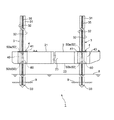
図1は、一実施形態に係る昇降装置4および該昇降装置4を備える作業台船1を示す模式的側面図である。図2は、図1に示した昇降装置4および作業台船1の平面図である。
[Overall structure of work platform]
FIG. 1 is a schematic side view showing an
作業台船1は、洋上構造体としてのプラットフォーム2と、上下の駆動手段としての昇降装置4と、支持柱としてのレグ3とを備える自己昇降式の作業台船(SEP:Self Elevating Platform)である。作業台船1は、船舶を停泊させる停泊施設として、洋上風力発電施設として、桟橋として、あるいは、海上ヘリポートとして使用される。プラットフォーム2の上には、船舶リフタや洋上風力タービンやクレーンなどが適宜に設置される。
The work pontoon 1 is a self-elevating work pontoon (SEP: Self Elevating Platform) including a
作業台船1を所定の据え付け地点まで曳航した後に、所定の据え付け地点において、昇降装置4により、レグ3をプラットフォーム2に対して下方に相対移動させる。レグ3のレグ先端33が海底9に押し込まれると、海底9からの反力を得ることができ、この反力によりプラットフォーム2を海面8よりも上方に上昇させることができる。プラットフォーム2は、波浪の影響を受けない高さ(例えば10m)まで持ち上げられる。この状態を保持することにより、作業台船1が海洋に立設される。
After towing the work pontoon 1 to a predetermined installation point, the
プラットフォーム2は、図1および図2に示すように、高さが低い略直方体形状をしており、上方から見ると略長方形であり、上板21、底板22、側板23および隔壁板24を備える。プラットフォーム2は、例えば、縦120m×横40m×高さ6mである。
As shown in FIGS. 1 and 2, the
プラットフォーム2の高さ方向(上下方向)に貫通したガイド穴25が、プラットフォーム2の四隅に形成されている。ガイド穴25は、例えば角形のレグ3がガイド穴25を上下方向に挿通できるように、例えば角形形状をしている。ガイド穴25の各コーナー部分(8ヶ所)には、穴側滑動部材29(図3に図示)として、例えば、MCナイロン板が張り付けられる。ガイド穴25の各コーナー部分に穴側滑動部材29を設けることにより、ガイド穴25におけるレグ3の滑動を長期間にわたって維持できる。MCナイロン板が摩耗したときには、新しいものに取り替えられる。上板21と底板22と側板23とで囲まれる内部空間26は、複数の隔壁板24によって間仕切りされている。
プラットフォーム2の内部空間26は、水密構造になっており、この水密構造によってプラットフォーム2は浮力を得ることができ、作業台船1全体が水に浮くことができる。したがって、作業台船1が海面8に浮上した状態で、作業台船1を曳航して据え付け地点まで移動させることができる。また、作業台船1は、スクリュープロペラなどの推進装置を備えることによって、自航して据え付け地点まで移動する態様にすることもできる。
The
図1に示すように、昇降装置4は、昇降ユニット40として、プラットフォーム2の四隅に形成されたガイド穴25を取り囲むように、プラットフォーム2に取り付けられている。昇降装置4は、昇降ユニット40の上端に設けられたフランジ41によって、プラットフォーム2の上板21に形成された係止段部に係止されて、上板21と面一に取り付けられている。当該構成によれば、作業者は、プラットフォーム2の上板21の上で安全に作業できる。
As shown in FIG. 1, the
図1に示すように、昇降装置4の昇降ユニット40が、プラットフォーム2の上板21および底板22の間の空間に収まるように配設されている。当該構成によれば、作業台船1の重心を下げることができ、作業台船1の曳航時での揺れに対する安定性を向上させることができる。また、昇降ユニット40は、公知のシール構造により水密構造になっている。
As shown in FIG. 1, the
〔レグの構造〕
図1および図4に示すように、プラットフォーム2を支持するレグ3は、中空の角形(断面が、例えば略正方形)の鋼管であり、対向する2面の係合面31と、対向する2面のガイド面32とを有する。レグ3は、例えば、3m角であり、50mの長さである。レグ3の各コーナー部分(1コーナー当たり2ヶ所)には、レグ側滑動部材39(図3に図示)として、例えばSUS304からなる平板が固着されている。レグ側滑動部材39は、レグ3の長手方向(上下方向)の略全長にわたって延びている。
[Leg structure]
As shown in FIG. 1 and FIG. 4, the
レグ3の各コーナー部分にレグ側滑動部材39を設けることにより、ガイド穴25におけるレグ3の滑動を長期間にわたって維持できる。レグ3をガイド穴25に挿通したとき、穴側滑動部材29とレグ側滑動部材39との間の隙間公差は、例えば3mm程度と小さく構成されている。これにより、レグ3の長手方向(上下方向)と直交する長手直交方向(横方向)での偏位を小さくでき、レグ3が上下方向に真っ直ぐに移動できる。
By providing the leg-
対向する2面の係合面31の幅方向中央には、それぞれ、複数の係合凹部35がレグ3の長手方向に形成されている。係合凹部35は、レグ3の長手直交方向(横方向)に貫通していない。好ましくは、複数の係合凹部35が、レグ3の長手方向に連続的に形成されている。当該構成によれば、レグ3を上下方向に微少量で相対移動させることができるので、微小な位置合わせを行うことができる。係合凹部35は、正面視で円形形状をしているとともに、断面視でレグ3の内側に向けて先細のテーパー形状(台形形状)をしている。当該構成によれば、後述するロック装置50の係合ピン56がレグ3の係合凹部35と容易に係合するとともに、係合ピン56と係合凹部35との間での係合接触面積が大きくなるので、ロック装置50によるロック固定を確実に行うことができる。係合凹部35は、例えば、挿入開口径が500mm、湾曲部が100mm、ピッチが600mmで形成されている。
A plurality of engagement recesses 35 are formed in the longitudinal direction of the
〔昇降装置の構造〕
図3は、図1に示した昇降装置4のロック装置50を説明する要部拡大図である。図4は、図1に示した昇降装置4のロック装置50によるロック固定を説明する図である。図5は、図1に示した昇降装置4の昇降シリンダ装置60による昇降動作を説明する模式的側面図である。ロック装置50は、或るレグ3の周囲に一側に2個、他側に2個の合計4個配設されている。すなわち、一側の係合面31の側に上下一対の昇降シリンダ装置60がレグ3の長手方向(上下方向)に離間して配設され、他側の係合面31の側に上下一対のシリンダ装置60がレグ3の長手方向(上下方向)に離間して配設されている。
[Structure of lifting device]
FIG. 3 is an enlarged view of the main parts for explaining the
図4に示すように、各昇降装置4は、上下一対のロック装置50と、昇降シリンダ装置60とを備える。上下一対のロック装置50は、上側のロック装置50aと下側のロック装置50bとから構成されている。上側のロック装置50aは、ブラケット72を介して可動ベース70に取り付けられて、レグ3の長手方向(上下方向)に可動である。下側のロック装置50bは、ブラケット72を介して固定ベース71に取り付けられて、レグ3の長手方向(上下方向)に不動であり且つ固定である。固定ベース71は、プラットフォーム2の上板21に固定されている。
As shown in FIG. 4, each lifting
図3に示すように、ロック装置50は、ロックシリンダ51とロックピストンロッド52とピストン55と係合ピン56とを有する。係合ピン56は、大略円錐台形状をしている。すなわち、係合ピン56は、正面視で円形形状をしているとともに、断面視で係合凹部35に向けて先細のテーパー形状(台形形状)にピン先端57の山型形状を加えた形状をしている。ロック装置50は、シール部材54を有するシール構造53により水密に構成されている。
As shown in FIG. 3, the
ロック装置50は、ピストン55を油圧などの流体で駆動して、ピストン55の先端に取り付けられた係合ピン56を、レグ3の長手方向(上下方向)と直交する長手直交方向(横方向)に駆動する。係合ピン56を、レグ3の係合凹部35に向けて駆動すると、係合ピン56が突出して係合凹部35に圧入されて係合する。このとき、係合ピン56の係合凸面58が係合凹部35の係合凹面36に対して周面状に密着して係合する。係合ピン56を、レグ3の係合凹部35とは反対側に駆動すると、係合ピン56が引っ込んで係合凹部35に対して非係合になる。このとき、係合ピン56の係合凸面58が係合凹部35の係合凹面36に対して非係合になる。
The
係合ピン56の係合凸面58の勾配が、レグ3の係合凹面36の勾配よりも大きいように構成されている。例えば、係合凸面58の勾配が15度であり、係合凹面36の勾配が14度である。言い換えると、係合凸面58のテーパー角度が30度であり、係合凹面36のテーパー角度が28度である。当該構成によれば、係合凸面58が係合凹面36の外側の挿入開口部分で係合するので、係合ピン56が係合凹部35との摩耗によって縮径しても、係合ピン56が係合凹部35の内側に向けてさらに突出して圧入することができるので、ロック装置50を長期間使用できる。
The slope of the engagement
図3に示すように、係合状態において、係合ピン56のピン先端57とレグ3の係合凹部35の内側部分との間で隙間を有するように構成されている。当該構成によれば、係合ピン56が係合凹部35との摩耗によって縮径しても、係合ピン56が係合凹部35の内側に向けてさらに突出して圧入することができるので、ロック装置50を長期間使用できる。
As shown in FIG. 3, in the engaged state, there is a gap between the
図4および図5を参照しながら、昇降装置4の昇降シリンダ装置60を説明する。或る1つのレグ3の周囲には、4個の昇降シリンダ装置60が配設されている。すなわち、一側の係合面31の側において2個の昇降シリンダ装置60がレグ3の長手直交方向(横方向)に離間して配設され、他側の係合面31の側において2個の昇降シリンダ装置60がレグ3の長手直交方向(横方向)に離間して配設されている。プラットフォーム2が4本のレグ3で支持されている場合、合計で16個の昇降シリンダ装置60が配設されている。1つの昇降シリンダ装置60は、例えば、1250トンの押し上げ能力と、1500mmのストロークを有する。したがって、作業船台1の全体では、例えば、2万トンの押し上げ能力を有する。
The
各昇降シリンダ装置60は、昇降シリンダ61と昇降ピストンロッド62と第1ポート66と第2ポート67とを有する。昇降シリンダ61は、シリンダ連結部材65を介して固定ベース71に取り付けられている。昇降ピストンロッド62は、ロッド連結部材63を介して可動ベース70に取り付けられている。
Each
各昇降シリンダ装置60は、昇降シリンダ61内のピストン(図示しない)を油圧などの流体で駆動して、ピストンに取り付けられた昇降ピストンロッド62を、レグ3の長手方向(上下方向)に駆動する。第2ポート67を通じて油圧を供給すると、ピストンおよび昇降ピストンロッド62が上昇する。昇降ピストンロッド62を上方に駆動すると、可動ベース70が上方に移動し、それにともなって上側のロック装置50aが上方に移動する。第1ポート66を通じて油圧を供給すると、ピストンおよび昇降ピストンロッド62が下降する。昇降ピストンロッド62を下方に駆動すると、可動ベース70が下方に移動し、それにともなって上側のロック装置50aが下方に移動する。したがって、昇降シリンダ装置60は、上側のロック装置50aを、下側のロック装置50bに対して互いに離れるかまたは近づくように、上側のロック装置50aおよび下側のロック装置50bのうちの一方(図示した実施形態では、上側のロック装置50a)を昇降させる。
Each
〔プラットフォームの昇降動作〕
上側のロック装置50aおよび下側のロック装置50bがプラットフォーム2の4隅にある各レグ3を保持した状態で、例えば、作業台船1を所定の据え付け地点まで曳航する。その後、所定の据え付け地点において、上側のロック装置50aおよび下側のロック装置50bの各係合ピン56を、レグ3の係合凹部35から離脱するように、上側のロック装置50aおよび下側のロック装置50bの各ロックピストンロッド52を駆動する。上側のロック装置50aおよび下側のロック装置50bから非係合となったレグ3は、自重で海底9まで直立状態で下降して、レグ先端33が海底9まで一気に到達する。これにより、レグ3の着底作業を短縮化できる。なお、時間を要するものの、後述する尺取り虫方式でレグ3を海底9まで下降させることもできる。
[Platform lifting operation]
With the
上側のロック装置50aに設けられた各係合ピン56と下側のロック装置50bに設けられた係合ピン56とが、レグ3の係合凹部35と交互に係合しながら、昇降シリンダ装置60の昇降ピストンロッド62を伸縮させることにより、レグ3をいわゆる尺取り虫方式に昇降させることができる。
Each of the engagement pins 56 provided on the
具体的には、下側のロック装置50bの係合ピン56がレグ3の係合凹部35と係合するとともに、上側のロック装置50aの係合ピン56がレグ3の係合凹部35と係合することを解除する。この状態で、昇降シリンダ装置60の昇降ピストンロッド62を突出させることにより、上側のロック装置50a(可動ベース70)が持ち上げる。その後、上側のロック装置50aの係合ピン56がレグ3の係合凹部35と係合するとともに、下側のロック装置50bの係合ピン56がレグ3の係合凹部35と係合することを解除する。この状態で、昇降シリンダ装置60の昇降ピストンロッド62を引っ込めることにより、下側のロック装置50b(プラットフォーム2)が持ち上げる。そして、下側のロック装置50bの係合ピン56がレグ3の係合凹部35と係合することにより、レグ3がプラットフォーム2にロック固定される。以上の動作を交互に繰り返すことにより、下側のロック装置50bが取り付けられたプラットフォーム2を徐々に上昇させることができる。また、プラットフォーム2を下降させる場合には、逆の動作を行えばよい。
Specifically, the
ロック装置50の係合ピン56がレグ3の係合凹部35と係合するとき、係合ピン56の先細のテーパー形状の係合凸面58が、係合凹部35の先細のテーパー形状の係合凹面に対して周面状に密着して接触する。これにより、係合ピン56と係合凹部35との間での係合接触面積が大きくなるとともに、係合ピン56と係合凹部35との間での係合の位置決めが容易になるので、ロック装置50によるロック固定を確実に行うことができる。また、複数の係合凹部35が、レグ3の長手方向に連続的に形成されているので、レグ3を長手方向(上下方向)に僅かに移動させることによって、プラットフォーム2の水平位置合わせを容易に行うことができる。
When the
〔レグに形成された係合凹部の変形例〕
図6は、レグ3に形成された係合凹部35の変形例を示す側面図である。上述したレグ3との相違点は、複数の係合凹部35が、レグ3の長手方向に離間して形成されていることである。係合凹部35は、例えば、挿入開口径が500mm、湾曲部が100mm、平坦部が200mm、ピッチが800mmで形成されている。
[Modification of engagement recess formed on leg]
FIG. 6 is a side view showing a modified example of the
この発明の具体的な実施の形態について説明したが、この発明は、上記実施形態に限定されるものではなく、この発明の範囲内で種々変更して実施することができる。 Although specific embodiments of the present invention have been described, the present invention is not limited to the above-described embodiments, and various modifications can be carried out within the scope of the present invention.
レグ3は、プラットフォーム2の4隅に配置される4本のみに限定されず、6本や8本などから構成されてもよい。また、レグ3の高さや径などは、プラットフォーム2の大きさなどによって適宜に決定できる。なお、プラットフォーム2のサイズが大きくて、レグ3のみでプラットフォーム2を十分に支持できない場合には、図示しない杭をレグ3の間に投入して設置することもできる。レグ3および杭でプラットフォーム2を支持した状態で、レグ3を杭に置換して、置換したレグ3を別の作業台船1に使用することもできる。このとき、レグ3の配置されていたガイド穴25にも、杭を投入して設置することができる。
The
この発明および実施形態をまとめると、次のようになる。 The present invention and embodiments are summarized as follows.
この発明の一態様に係る昇降装置4は、
プラットフォーム2を支持するレグ3に対して相対移動を可能にする昇降装置4であって、
前記レグ3の対向する2面の係合面31には、複数の係合凹部35が前記レグ3の長手方向に形成されており、
前記昇降装置4は、
前記レグ3をロック固定するための係合ピン56を駆動して、前記係合ピン56の係合凸面58を前記係合凹部35の係合凹面36に係合させる一対のロック装置50と、
前記一対のロック装置50が互いに離れるかまたは近づくように、前記一対のロック装置50のうちの一方を昇降させる昇降シリンダ装置60とを備え、
前記係合凹部35が前記レグ3の内側に向けて先細のテーパー形状をしているとともに、前記係合ピン56が前記係合凹部35に向けて先細のテーパー形状をしていることを特徴とする。
The
A
A plurality of engaging
The
A pair of locking
An elevating
The
上記構成によれば、ロック装置50の係合ピン56とレグ3の係合凹部35とが互いにテーパー形状をしているので、両者が容易に且つ確実に係合する。したがって、ロック装置50の係合ピン56とレグ3の係合凹部35との間での係合が安定するとともに、レグ3の重量アップやコストアップを招くことがない。
According to the above configuration, the
また、一実施形態の昇降装置4では、
前記複数の係合凹部35が、前記レグ3の長手方向に連続的に形成されている。
Further, in the
The plurality of engaging
上記実施形態によれば、レグ3を長手方向(上下方向)に僅かに移動させることができるので、プラットフォーム2の水平位置合わせを容易に行うことができる。
According to the above-described embodiment, since the
また、一実施形態の昇降装置4では、
前記係合ピン56が、大略円錐台形状をしている。
Further, in the
The
上記実施形態によれば、ロック装置50の係合ピン56がレグ3の係合凹部35と容易に係合するとともに、係合ピン56と係合凹部35との間での係合接触面積が大きくなるので、ロック装置50によるロック固定を確実に行うことができる。
According to the above-described embodiment, the
また、一実施形態の昇降装置4では、
前記係合凸面58の勾配が、前記係合凹面36の勾配よりも大きい。
Further, in the
The slope of the engagement
上記実施形態によれば、係合凸面58が係合凹面36の外側の挿入開口部分で係合するので、係合ピン56が係合凹部35との摩耗によって縮径しても、係合ピン56が係合凹部35の内側に向けてさらに突出して圧入することができるので、ロック装置50を長期間使用できる。
According to the above-described embodiment, since the engaging
また、一実施形態の昇降装置4では、
前記レグ3が角形をしており、前記レグ3のコーナー部分にはレグ側滑動部材39が設けられているとともに、
前記プラットフォーム2に設けられた角形のガイド穴25のコーナー部分には穴側滑動部材29が設けられている。
Further, in the
The
A hole-
上記実施形態によれば、ガイド穴25におけるレグ3の滑動を長期間にわたって維持できる。
According to the above-described embodiment, the slide of the
また、一実施形態の昇降装置4では、
前記昇降装置4が、前記プラットフォーム2の上板21および底板22の間に収まるように配設されている。
Further, in the
The elevating
上記実施形態によれば、作業台船1の重心を下げることができ、作業台船1の曳航時での揺れに対する安定性を向上させることができる。 According to the above embodiment, the center of gravity of the work pontoon 1 can be lowered, and the stability of the work pontoon 1 against shaking during towing can be improved.
別の局面では、この発明の作業台船1は、請求項1から請求項6のいずれか1つに記載の昇降装置4を備えることを特徴とする。
In another aspect, a work platform 1 of the present invention is characterized by including the
この発明の作業台船1では、ロック装置50の係合ピン56とレグ3の係合凹部35とが互いにテーパー形状をしているので、両者が容易に且つ確実に係合する。したがって、ロック装置50の係合ピン56とレグ3の係合凹部35との間での係合が安定するとともに、レグ3の重量アップやコストアップを招くことがない。
In the work platform 1 of the present invention, since the
1…作業台船
2…プラットフォーム
3…レグ
4…昇降装置
8…海面
9…海底
21…上板
22…底板
23…側板
24…隔壁板
25…ガイド穴
26…内部空間
29…穴側滑動部材
31…係合面
32…ガイド面
33…レグ先端
35…係合凹部(被係合部)
36…係合凹面
39…レグ側滑動部材
40…昇降ユニット
41…フランジ
50…ロック装置
50a…上側のロック装置
50b…下側のロック装置
51…ロックシリンダ
52…ロックピストンロッド
53…シール構造
54…シール部材
55…ピストン
56…係合ピン
57…ピン先端
58…係合凸面
60…昇降シリンダ装置
61…昇降シリンダ
62…昇降ピストンロッド
63…ロッド連結部材
65…シリンダ連結部材
66…第1ポート
67…第2ポート
70…可動ベース
71…固定ベース
72…ブラケット
1 ... Workbench
2 ...
36 ... Engagement
Claims (7)
前記レグの対向する2面の係合面には、複数の係合凹部が前記レグの長手方向に形成されており、
前記昇降装置は、
前記レグをロック固定するための係合ピンを駆動して、前記係合ピンの係合凸面を前記係合凹部の係合凹面に係合させる一対のロック装置と、
前記一対のロック装置が互いに離れるかまたは近づくように、前記一対のロック装置のうちの一方を昇降させる昇降シリンダ装置とを備え、
前記係合凹部が、正面視で円形形状をしているとともに、断面視で前記レグの内側に向けて先細のテーパー形状をしているとともに、前記係合ピンが、正面視で円形形状をしているとともに、断面視で前記係合凹部に向けて先細のテーパー形状をしており、前記係合ピンが前記係合凹部に対して周状に係合することを特徴とする、昇降装置。 A lifting device that enables relative movement with respect to a leg that supports a platform,
A plurality of engaging recesses are formed in the two facing surfaces of the leg in the longitudinal direction of the leg,
The lifting device is
A pair of locking devices that drive an engagement pin for locking and fixing the leg to engage an engagement convex surface of the engagement pin with an engagement concave surface of the engagement concave portion,
An elevator cylinder device that raises and lowers one of the pair of locking devices so that the pair of locking devices separates or approaches each other.
The engagement recess has a circular shape in a front view, and has a taper shape that is tapered toward the inside of the leg in a cross-sectional view, and the engagement pin has a circular shape in a front view. In addition , the lifting device has a taper shape that is tapered toward the engaging recess in a sectional view, and the engaging pin engages with the engaging recess in a circumferential shape .
前記プラットフォームに設けられた角形のガイド穴のコーナー部分には穴側滑動部材が設けられていることを特徴とする、請求項1から請求項4のいずれか1項に記載の昇降装置。 The leg has a rectangular shape, and a leg-side sliding member is provided at a corner portion of the leg,
The lift device according to any one of claims 1 to 4, wherein a hole-side sliding member is provided at a corner portion of a rectangular guide hole provided in the platform.
Priority Applications (1)
| Application Number | Priority Date | Filing Date | Title |
|---|---|---|---|
| JP2018236570A JP6694639B1 (en) | 2018-12-18 | 2018-12-18 | Lifting device and work table boat equipped with the lifting device |
Applications Claiming Priority (1)
| Application Number | Priority Date | Filing Date | Title |
|---|---|---|---|
| JP2018236570A JP6694639B1 (en) | 2018-12-18 | 2018-12-18 | Lifting device and work table boat equipped with the lifting device |
Publications (2)
| Publication Number | Publication Date |
|---|---|
| JP6694639B1 true JP6694639B1 (en) | 2020-05-20 |
| JP2020097472A JP2020097472A (en) | 2020-06-25 |
Family
ID=70682320
Family Applications (1)
| Application Number | Title | Priority Date | Filing Date |
|---|---|---|---|
| JP2018236570A Active JP6694639B1 (en) | 2018-12-18 | 2018-12-18 | Lifting device and work table boat equipped with the lifting device |
Country Status (1)
| Country | Link |
|---|---|
| JP (1) | JP6694639B1 (en) |
-
2018
- 2018-12-18 JP JP2018236570A patent/JP6694639B1/en active Active
Also Published As
| Publication number | Publication date |
|---|---|
| JP2020097472A (en) | 2020-06-25 |
Similar Documents
| Publication | Publication Date | Title |
|---|---|---|
| US9499240B2 (en) | Floating marine structure | |
| US3797256A (en) | Jack-up type offshore platform apparatus | |
| US4723875A (en) | Deep water support assembly for a jack-up type platform | |
| US3872679A (en) | Apparatus and method for reducing the forces on extendible legs of a floating vessel | |
| US4902169A (en) | Jack-up type platform including adjustable stop assembly | |
| CN109723049B (en) | Self-elevating platform and elevating method thereof | |
| JP5119346B2 (en) | Lifting thruster | |
| JP6735050B1 (en) | Stand lifting device for ships | |
| GB1599631A (en) | Self elevating offshore platforms and methods of fabricating the same | |
| JP6694639B1 (en) | Lifting device and work table boat equipped with the lifting device | |
| US6968797B2 (en) | Method for installing a self-floating deck structure onto a buoyant substructure | |
| US2877629A (en) | Method and apparatus for erecting a deep water offshore platform | |
| KR101934389B1 (en) | Floating structure | |
| US20040159276A1 (en) | Method for installing a self-floating deck structure onto a buoyant substructure | |
| JP6694640B1 (en) | Hydraulic cylinder device | |
| GB2080860A (en) | A process for mounting in relatively shallow or moderately deep water and installing at the work site a drilling and oil-production platform with base-weight. | |
| JP7044278B1 (en) | Lifting device for pedestals for ships | |
| CN211171979U (en) | Pile stabilizing platform capable of being lifted integrally | |
| CN111997028A (en) | Self-elevating platform and lifting system and lifting method thereof | |
| JPH0342107Y2 (en) | ||
| CN115476980A (en) | Offshore operation platform capable of standing at bottom | |
| JP2023118542A (en) | Attachment for structure installation and installation method for structure with attachment thereon | |
| GB2314576A (en) | Offshore platform assembly | |
| CN106638532B (en) | The double continuous lifting device of master cylinder | |
| KR20130117173A (en) | Sub support of lmu |
Legal Events
| Date | Code | Title | Description |
|---|---|---|---|
| A621 | Written request for application examination |
Free format text: JAPANESE INTERMEDIATE CODE: A621 Effective date: 20181227 |
|
| A131 | Notification of reasons for refusal |
Free format text: JAPANESE INTERMEDIATE CODE: A131 Effective date: 20190903 |
|
| A521 | Request for written amendment filed |
Free format text: JAPANESE INTERMEDIATE CODE: A523 Effective date: 20191002 |
|
| TRDD | Decision of grant or rejection written | ||
| A01 | Written decision to grant a patent or to grant a registration (utility model) |
Free format text: JAPANESE INTERMEDIATE CODE: A01 Effective date: 20200324 |
|
| A61 | First payment of annual fees (during grant procedure) |
Free format text: JAPANESE INTERMEDIATE CODE: A61 Effective date: 20200413 |
|
| R150 | Certificate of patent or registration of utility model |
Ref document number: 6694639 Country of ref document: JP Free format text: JAPANESE INTERMEDIATE CODE: R150 |
|
| R250 | Receipt of annual fees |
Free format text: JAPANESE INTERMEDIATE CODE: R250 |
|
| R250 | Receipt of annual fees |
Free format text: JAPANESE INTERMEDIATE CODE: R250 |