JP6692709B2 - Method for manufacturing joined body, connection method - Google Patents
Method for manufacturing joined body, connection method Download PDFInfo
- Publication number
- JP6692709B2 JP6692709B2 JP2016125983A JP2016125983A JP6692709B2 JP 6692709 B2 JP6692709 B2 JP 6692709B2 JP 2016125983 A JP2016125983 A JP 2016125983A JP 2016125983 A JP2016125983 A JP 2016125983A JP 6692709 B2 JP6692709 B2 JP 6692709B2
- Authority
- JP
- Japan
- Prior art keywords
- bonding
- pressure
- light
- image display
- plate
- Prior art date
- Legal status (The legal status is an assumption and is not a legal conclusion. Google has not performed a legal analysis and makes no representation as to the accuracy of the status listed.)
- Active
Links
- 238000000034 method Methods 0.000 title claims description 29
- 238000004519 manufacturing process Methods 0.000 title claims description 22
- 239000011347 resin Substances 0.000 claims description 85
- 229920005989 resin Polymers 0.000 claims description 85
- 239000012298 atmosphere Substances 0.000 claims description 53
- 239000000463 material Substances 0.000 claims description 28
- 239000007788 liquid Substances 0.000 claims description 26
- 239000010410 layer Substances 0.000 description 59
- 239000011342 resin composition Substances 0.000 description 47
- 239000006059 cover glass Substances 0.000 description 43
- 239000004973 liquid crystal related substance Substances 0.000 description 43
- 230000000052 comparative effect Effects 0.000 description 17
- 230000003287 optical effect Effects 0.000 description 16
- 238000005516 engineering process Methods 0.000 description 13
- 238000010030 laminating Methods 0.000 description 13
- NIXOWILDQLNWCW-UHFFFAOYSA-M Acrylate Chemical compound [O-]C(=O)C=C NIXOWILDQLNWCW-UHFFFAOYSA-M 0.000 description 10
- 238000001723 curing Methods 0.000 description 10
- -1 polyethylene terephthalate Polymers 0.000 description 8
- 230000006837 decompression Effects 0.000 description 7
- 239000011248 coating agent Substances 0.000 description 6
- 238000000576 coating method Methods 0.000 description 6
- RSWGJHLUYNHPMX-UHFFFAOYSA-N Abietic-Saeure Natural products C12CCC(C(C)C)=CC2=CCC2C1(C)CCCC2(C)C(O)=O RSWGJHLUYNHPMX-UHFFFAOYSA-N 0.000 description 5
- KHPCPRHQVVSZAH-HUOMCSJISA-N Rosin Natural products O(C/C=C/c1ccccc1)[C@H]1[C@H](O)[C@@H](O)[C@@H](O)[C@@H](CO)O1 KHPCPRHQVVSZAH-HUOMCSJISA-N 0.000 description 5
- 239000000853 adhesive Substances 0.000 description 5
- 230000001070 adhesive effect Effects 0.000 description 5
- 230000001678 irradiating effect Effects 0.000 description 5
- 229920001195 polyisoprene Polymers 0.000 description 5
- KHPCPRHQVVSZAH-UHFFFAOYSA-N trans-cinnamyl beta-D-glucopyranoside Natural products OC1C(O)C(O)C(CO)OC1OCC=CC1=CC=CC=C1 KHPCPRHQVVSZAH-UHFFFAOYSA-N 0.000 description 5
- 239000000654 additive Substances 0.000 description 4
- 238000006073 displacement reaction Methods 0.000 description 4
- 239000004014 plasticizer Substances 0.000 description 4
- 150000003505 terpenes Chemical class 0.000 description 4
- 235000007586 terpenes Nutrition 0.000 description 4
- 239000005062 Polybutadiene Substances 0.000 description 3
- 239000004820 Pressure-sensitive adhesive Substances 0.000 description 3
- 238000006243 chemical reaction Methods 0.000 description 3
- 239000003999 initiator Substances 0.000 description 3
- 230000002093 peripheral effect Effects 0.000 description 3
- 239000004033 plastic Substances 0.000 description 3
- 229920003023 plastic Polymers 0.000 description 3
- 229920002857 polybutadiene Polymers 0.000 description 3
- 239000010409 thin film Substances 0.000 description 3
- KWOLFJPFCHCOCG-UHFFFAOYSA-N Acetophenone Chemical compound CC(=O)C1=CC=CC=C1 KWOLFJPFCHCOCG-UHFFFAOYSA-N 0.000 description 2
- 239000004902 Softening Agent Substances 0.000 description 2
- 238000001035 drying Methods 0.000 description 2
- 230000000694 effects Effects 0.000 description 2
- 229920001971 elastomer Polymers 0.000 description 2
- 150000002148 esters Chemical class 0.000 description 2
- 239000002184 metal Substances 0.000 description 2
- 238000002156 mixing Methods 0.000 description 2
- 238000000465 moulding Methods 0.000 description 2
- 238000000016 photochemical curing Methods 0.000 description 2
- 230000000704 physical effect Effects 0.000 description 2
- 239000005020 polyethylene terephthalate Substances 0.000 description 2
- 229920000139 polyethylene terephthalate Polymers 0.000 description 2
- 229920000642 polymer Polymers 0.000 description 2
- 229920000193 polymethacrylate Polymers 0.000 description 2
- 229920002635 polyurethane Polymers 0.000 description 2
- 239000004814 polyurethane Substances 0.000 description 2
- 239000005060 rubber Substances 0.000 description 2
- 238000000926 separation method Methods 0.000 description 2
- 238000004904 shortening Methods 0.000 description 2
- CWERGRDVMFNCDR-UHFFFAOYSA-N thioglycolic acid Chemical compound OC(=O)CS CWERGRDVMFNCDR-UHFFFAOYSA-N 0.000 description 2
- 238000002834 transmittance Methods 0.000 description 2
- DGVVWUTYPXICAM-UHFFFAOYSA-N β‐Mercaptoethanol Chemical compound OCCS DGVVWUTYPXICAM-UHFFFAOYSA-N 0.000 description 2
- DTGKSKDOIYIVQL-WEDXCCLWSA-N (+)-borneol Chemical group C1C[C@@]2(C)[C@@H](O)C[C@@H]1C2(C)C DTGKSKDOIYIVQL-WEDXCCLWSA-N 0.000 description 1
- QNODIIQQMGDSEF-UHFFFAOYSA-N (1-hydroxycyclohexyl)-phenylmethanone Chemical compound C=1C=CC=CC=1C(=O)C1(O)CCCCC1 QNODIIQQMGDSEF-UHFFFAOYSA-N 0.000 description 1
- ILBBNQMSDGAAPF-UHFFFAOYSA-N 1-(6-hydroxy-6-methylcyclohexa-2,4-dien-1-yl)propan-1-one Chemical compound CCC(=O)C1C=CC=CC1(C)O ILBBNQMSDGAAPF-UHFFFAOYSA-N 0.000 description 1
- 239000012956 1-hydroxycyclohexylphenyl-ketone Substances 0.000 description 1
- BDERNNFJNOPAEC-UHFFFAOYSA-N 1-propanol Substances CCCO BDERNNFJNOPAEC-UHFFFAOYSA-N 0.000 description 1
- OWHSTLLOZWTNTQ-UHFFFAOYSA-N 2-ethylhexyl 2-sulfanylacetate Chemical compound CCCCC(CC)COC(=O)CS OWHSTLLOZWTNTQ-UHFFFAOYSA-N 0.000 description 1
- PCKZAVNWRLEHIP-UHFFFAOYSA-N 2-hydroxy-1-[4-[[4-(2-hydroxy-2-methylpropanoyl)phenyl]methyl]phenyl]-2-methylpropan-1-one Chemical compound C1=CC(C(=O)C(C)(O)C)=CC=C1CC1=CC=C(C(=O)C(C)(C)O)C=C1 PCKZAVNWRLEHIP-UHFFFAOYSA-N 0.000 description 1
- 239000004925 Acrylic resin Substances 0.000 description 1
- 229920000178 Acrylic resin Polymers 0.000 description 1
- WOBHKFSMXKNTIM-UHFFFAOYSA-N Hydroxyethyl methacrylate Chemical compound CC(=C)C(=O)OCCO WOBHKFSMXKNTIM-UHFFFAOYSA-N 0.000 description 1
- CERQOIWHTDAKMF-UHFFFAOYSA-M Methacrylate Chemical compound CC(=C)C([O-])=O CERQOIWHTDAKMF-UHFFFAOYSA-M 0.000 description 1
- 239000006087 Silane Coupling Agent Substances 0.000 description 1
- 125000005396 acrylic acid ester group Chemical group 0.000 description 1
- NIXOWILDQLNWCW-UHFFFAOYSA-N acrylic acid group Chemical group C(C=C)(=O)O NIXOWILDQLNWCW-UHFFFAOYSA-N 0.000 description 1
- 125000001931 aliphatic group Chemical group 0.000 description 1
- 239000003963 antioxidant agent Substances 0.000 description 1
- 230000003078 antioxidant effect Effects 0.000 description 1
- RWCCWEUUXYIKHB-UHFFFAOYSA-N benzophenone Chemical compound C=1C=CC=CC=1C(=O)C1=CC=CC=C1 RWCCWEUUXYIKHB-UHFFFAOYSA-N 0.000 description 1
- 239000012965 benzophenone Substances 0.000 description 1
- 125000001797 benzyl group Chemical group [H]C1=C([H])C([H])=C(C([H])=C1[H])C([H])([H])* 0.000 description 1
- GCTPMLUUWLLESL-UHFFFAOYSA-N benzyl prop-2-enoate Chemical compound C=CC(=O)OCC1=CC=CC=C1 GCTPMLUUWLLESL-UHFFFAOYSA-N 0.000 description 1
- MQDJYUACMFCOFT-UHFFFAOYSA-N bis[2-(1-hydroxycyclohexyl)phenyl]methanone Chemical compound C=1C=CC=C(C(=O)C=2C(=CC=CC=2)C2(O)CCCCC2)C=1C1(O)CCCCC1 MQDJYUACMFCOFT-UHFFFAOYSA-N 0.000 description 1
- 239000012986 chain transfer agent Substances 0.000 description 1
- 239000003795 chemical substances by application Substances 0.000 description 1
- 238000003776 cleavage reaction Methods 0.000 description 1
- 238000004132 cross linking Methods 0.000 description 1
- WNAHIZMDSQCWRP-UHFFFAOYSA-N dodecane-1-thiol Chemical compound CCCCCCCCCCCCS WNAHIZMDSQCWRP-UHFFFAOYSA-N 0.000 description 1
- UHESRSKEBRADOO-UHFFFAOYSA-N ethyl carbamate;prop-2-enoic acid Chemical compound OC(=O)C=C.CCOC(N)=O UHESRSKEBRADOO-UHFFFAOYSA-N 0.000 description 1
- 238000005187 foaming Methods 0.000 description 1
- 239000011521 glass Substances 0.000 description 1
- 230000001771 impaired effect Effects 0.000 description 1
- FPYJFEHAWHCUMM-UHFFFAOYSA-N maleic anhydride Chemical compound O=C1OC(=O)C=C1 FPYJFEHAWHCUMM-UHFFFAOYSA-N 0.000 description 1
- 230000013011 mating Effects 0.000 description 1
- 125000005397 methacrylic acid ester group Chemical group 0.000 description 1
- 239000000203 mixture Substances 0.000 description 1
- 238000012986 modification Methods 0.000 description 1
- 230000004048 modification Effects 0.000 description 1
- 239000000178 monomer Substances 0.000 description 1
- 125000002347 octyl group Chemical group [H]C([*])([H])C([H])([H])C([H])([H])C([H])([H])C([H])([H])C([H])([H])C([H])([H])C([H])([H])[H] 0.000 description 1
- REJKHFKLPFJGAQ-UHFFFAOYSA-N oxiran-2-ylmethanethiol Chemical compound SCC1CO1 REJKHFKLPFJGAQ-UHFFFAOYSA-N 0.000 description 1
- 239000003208 petroleum Substances 0.000 description 1
- 239000005011 phenolic resin Substances 0.000 description 1
- 125000001997 phenyl group Chemical group [H]C1=C([H])C([H])=C(*)C([H])=C1[H] 0.000 description 1
- 229920003207 poly(ethylene-2,6-naphthalate) Polymers 0.000 description 1
- 229920000515 polycarbonate Polymers 0.000 description 1
- 239000004417 polycarbonate Substances 0.000 description 1
- 239000011112 polyethylene naphthalate Substances 0.000 description 1
- 239000003505 polymerization initiator Substances 0.000 description 1
- 238000003825 pressing Methods 0.000 description 1
- FZYCEURIEDTWNS-UHFFFAOYSA-N prop-1-en-2-ylbenzene Chemical compound CC(=C)C1=CC=CC=C1.CC(=C)C1=CC=CC=C1 FZYCEURIEDTWNS-UHFFFAOYSA-N 0.000 description 1
- 230000007017 scission Effects 0.000 description 1
- 238000007650 screen-printing Methods 0.000 description 1
- 239000006097 ultraviolet radiation absorber Substances 0.000 description 1
Images


Classifications
-
- B—PERFORMING OPERATIONS; TRANSPORTING
- B32—LAYERED PRODUCTS
- B32B—LAYERED PRODUCTS, i.e. PRODUCTS BUILT-UP OF STRATA OF FLAT OR NON-FLAT, e.g. CELLULAR OR HONEYCOMB, FORM
- B32B37/00—Methods or apparatus for laminating, e.g. by curing or by ultrasonic bonding
- B32B37/10—Methods or apparatus for laminating, e.g. by curing or by ultrasonic bonding characterised by the pressing technique, e.g. using action of vacuum or fluid pressure
-
- B—PERFORMING OPERATIONS; TRANSPORTING
- B32—LAYERED PRODUCTS
- B32B—LAYERED PRODUCTS, i.e. PRODUCTS BUILT-UP OF STRATA OF FLAT OR NON-FLAT, e.g. CELLULAR OR HONEYCOMB, FORM
- B32B37/00—Methods or apparatus for laminating, e.g. by curing or by ultrasonic bonding
- B32B37/12—Methods or apparatus for laminating, e.g. by curing or by ultrasonic bonding characterised by using adhesives
-
- B—PERFORMING OPERATIONS; TRANSPORTING
- B32—LAYERED PRODUCTS
- B32B—LAYERED PRODUCTS, i.e. PRODUCTS BUILT-UP OF STRATA OF FLAT OR NON-FLAT, e.g. CELLULAR OR HONEYCOMB, FORM
- B32B37/00—Methods or apparatus for laminating, e.g. by curing or by ultrasonic bonding
- B32B37/10—Methods or apparatus for laminating, e.g. by curing or by ultrasonic bonding characterised by the pressing technique, e.g. using action of vacuum or fluid pressure
- B32B37/1018—Methods or apparatus for laminating, e.g. by curing or by ultrasonic bonding characterised by the pressing technique, e.g. using action of vacuum or fluid pressure using only vacuum
-
- C—CHEMISTRY; METALLURGY
- C09—DYES; PAINTS; POLISHES; NATURAL RESINS; ADHESIVES; COMPOSITIONS NOT OTHERWISE PROVIDED FOR; APPLICATIONS OF MATERIALS NOT OTHERWISE PROVIDED FOR
- C09J—ADHESIVES; NON-MECHANICAL ASPECTS OF ADHESIVE PROCESSES IN GENERAL; ADHESIVE PROCESSES NOT PROVIDED FOR ELSEWHERE; USE OF MATERIALS AS ADHESIVES
- C09J201/00—Adhesives based on unspecified macromolecular compounds
-
- C—CHEMISTRY; METALLURGY
- C09—DYES; PAINTS; POLISHES; NATURAL RESINS; ADHESIVES; COMPOSITIONS NOT OTHERWISE PROVIDED FOR; APPLICATIONS OF MATERIALS NOT OTHERWISE PROVIDED FOR
- C09J—ADHESIVES; NON-MECHANICAL ASPECTS OF ADHESIVE PROCESSES IN GENERAL; ADHESIVE PROCESSES NOT PROVIDED FOR ELSEWHERE; USE OF MATERIALS AS ADHESIVES
- C09J5/00—Adhesive processes in general; Adhesive processes not provided for elsewhere, e.g. relating to primers
-
- G—PHYSICS
- G02—OPTICS
- G02F—OPTICAL DEVICES OR ARRANGEMENTS FOR THE CONTROL OF LIGHT BY MODIFICATION OF THE OPTICAL PROPERTIES OF THE MEDIA OF THE ELEMENTS INVOLVED THEREIN; NON-LINEAR OPTICS; FREQUENCY-CHANGING OF LIGHT; OPTICAL LOGIC ELEMENTS; OPTICAL ANALOGUE/DIGITAL CONVERTERS
- G02F1/00—Devices or arrangements for the control of the intensity, colour, phase, polarisation or direction of light arriving from an independent light source, e.g. switching, gating or modulating; Non-linear optics
- G02F1/01—Devices or arrangements for the control of the intensity, colour, phase, polarisation or direction of light arriving from an independent light source, e.g. switching, gating or modulating; Non-linear optics for the control of the intensity, phase, polarisation or colour
- G02F1/13—Devices or arrangements for the control of the intensity, colour, phase, polarisation or direction of light arriving from an independent light source, e.g. switching, gating or modulating; Non-linear optics for the control of the intensity, phase, polarisation or colour based on liquid crystals, e.g. single liquid crystal display cells
-
- B—PERFORMING OPERATIONS; TRANSPORTING
- B32—LAYERED PRODUCTS
- B32B—LAYERED PRODUCTS, i.e. PRODUCTS BUILT-UP OF STRATA OF FLAT OR NON-FLAT, e.g. CELLULAR OR HONEYCOMB, FORM
- B32B2457/00—Electrical equipment
- B32B2457/20—Displays, e.g. liquid crystal displays, plasma displays
Description
本技術は、真空雰囲気下で、第1の貼合部材と第2の貼合部材とを、貼合樹脂材を介して貼り合わせて接合体を製造する製造方法、及び第1の貼合部材と第2の貼合部材とを、貼合樹脂材を介して接続する接続方法に関する。 The present technology is a manufacturing method for manufacturing a bonded body by bonding a first bonding member and a second bonding member via a bonding resin material under a vacuum atmosphere, and a first bonding member. And a second bonding member are connected to each other via a bonding resin material.
スマートホン等の情報端末に用いられている液晶表示パネル等の画像表示装置は、液晶表示パネルや有機ELパネル等の画像表示部材と光透過性カバー部材との間に、光硬化性樹脂組成物を配した後、その組成物に紫外線を照射して硬化させて光透過性硬化樹脂層とし、それにより画像表示部材と光透過性カバー部材とを接着・積層することにより製造されている。 An image display device such as a liquid crystal display panel used for an information terminal such as a smart phone has a photocurable resin composition between an image display member such as a liquid crystal display panel or an organic EL panel and a light transmissive cover member. And then the composition is irradiated with ultraviolet rays to be cured to form a light-transmissive cured resin layer, and the image display member and the light-transmissive cover member are thereby bonded and laminated.
画像表示部材と光透過性カバー部材とが光透過性硬化樹脂組成物を介して接続する方法として真空貼合工法が用いられている。図9〜図11に真空貼合工法の一例を示す。図9に示すように、光透過性カバー部材50は、貼り合わせ面に光透過性樹脂組成物51が塗布され、適宜仮硬化された後、真空チャンバー55内において、第1の貼合プレート52によって貼り合わせ面を下方に向けて支持される。また、画像表示部材53は、真空チャンバー55内において、第2の貼合プレート54によって貼り合わせ面を上方に向けて支持される。
A vacuum bonding method is used as a method for connecting the image display member and the light-transmitting cover member via the light-transmitting cured resin composition. 9 to 11 show an example of the vacuum bonding method. As shown in FIG. 9, the light-
次いで、真空チャンバー55内が排気され真空雰囲気とされる。その後、図10に示すように、第2の貼り合せプレート54が上昇し、画像表示部材53が光透過性樹脂組成物51を介して光透過性カバー部材50に押し当てられる。光透過性カバー部材50及び画像表示部材53は、真空雰囲気下で光透過性樹脂組成物51を介して貼り合わされることにより、貼り合わせ面や光透過性硬化樹脂層中に気泡が残存することを防止することができる。
Then, the inside of the
次いで、図11に示すように、第1の貼り合せプレート52による光透過性カバー部材50の支持が解除され、第2の貼り合せプレート54が下降される。この状態で、真空チャンバー55内が大気圧に開放され、光透過性カバー部材50及び画像表示部材53の接合体56が真空チャンバー55から取り出される。
Next, as shown in FIG. 11, the support of the light
その後、接合体56は、光透過性樹脂組成物51が硬化されることにより、光透過性硬化樹脂層を介して接続された光透過性カバー部材50及び画像表示部材53の画像表示装置が完成する。
After that, in the
近年は、画像表示装置の狭額縁化が進み光透過性カバー部材50と画像表示部材53との貼合精度に対する要求は高くなっている。しかし、真空貼合工法においては、大気圧解放を行った際、真空チャンパー55内に急激な圧力変動や乱気流が発生し、特に光透過性樹脂組成物51が液状やゲル状であった場合、光透過性カバー部材50と画像表示部材53との貼合位置にズレが生じてしまう。
In recent years, the frame of the image display device has become narrower, and the demand for the bonding accuracy of the light
大気圧の開放時間を長くとることで圧力変動や乱気流を小さくすることも可能であるが、未硬化の光透過性樹脂組成物51を介して接合された光透過性カバー部材50の移動を完全に抑制することは難しく、また製造タクトの短縮の要求から大気圧の開放時間を長くとることには限界もある。
Although it is possible to reduce pressure fluctuations and turbulence by increasing the atmospheric pressure release time, it is possible to completely move the light-
また、大気導入時の影響を無くす為には、貼合プレートの下降をせずに大気を導入する工法も考えられる。しかし、この場合、大気導入が完了するまで光透過性カバー部材50及び画像表示部材53に貼合圧力が負荷された状態となり、必要以上に加圧時間を要する事となる。このため、光透過性樹脂組成物51に残存応力が介在し、部分的に色ムラが発生するおそれがある他、薄型化が進展している画像表示部材に対する負荷が過大となり、反りの発生や損傷を与える恐れもある。
Further, in order to eliminate the influence at the time of introducing the atmosphere, a method of introducing the atmosphere without lowering the bonding plate may be considered. However, in this case, the bonding pressure is applied to the light
そこで、本技術は、真空雰囲気下で、第1の貼合部材と第2の貼合部材とを、貼合樹脂材を介して貼り合わせて接合体を製造するに際し、貼り合せ位置ズレを防止するとともに、第1、第2の貼り合せ部材及び貼り合せ樹脂材に対する過大な負荷を抑制することができる接合体の製造方法、及び接続方法を提供することを目的とする。 Therefore, the present technology prevents the displacement of the bonding position when manufacturing the bonded body by bonding the first bonding member and the second bonding member via the bonding resin material in a vacuum atmosphere. In addition, it is an object of the present invention to provide a method for manufacturing a joined body and a connecting method capable of suppressing an excessive load on the first and second bonding members and the bonding resin material.
上述した課題を解決するために、本技術に係る接合体の製造方法は、真空雰囲気下で、第1の貼合プレートに支持された第1の貼合部材と第2の貼合プレートに支持された第2の貼合部材とを、貼合樹脂材を介して所定の貼合圧力で貼り合わせる工程と、次いで、上記第1、第2の貼合部材が上記第1、第2の貼合プレートに挟持された状態で上記第1、第2の貼合プレートを離間させて、上記貼合圧力を減じる工程と、次いで、真空雰囲気下から大気圧へ開放する工程と、次いで、上記第1、第2の貼合部材に対する貼合圧力を解除する工程とを有するものである。 In order to solve the above-mentioned subject, the manufacturing method of the joined object concerning this art is supported by the 1st pasting member and the 2nd pasting plate supported by the 1st pasting plate under a vacuum atmosphere. A step of bonding the formed second bonding member with a predetermined bonding pressure via a bonding resin material, and then the first and second bonding members are bonded to the first and second bonding members. A step of reducing the bonding pressure by separating the first and second bonding plates in a state of being sandwiched by the bonding plate, a step of releasing from a vacuum atmosphere to atmospheric pressure, and then a step of And a step of releasing the bonding pressure applied to the second bonding member.
また、本技術に係る接続方法は、真空雰囲気下で、第1の貼合プレートに支持された第1の貼合部材と第2の貼合プレートに支持された第2の貼合部材とを、貼合樹脂材を介して所定の貼合圧力で貼り合わせる工程と、次いで、上記第1、第2の貼合部材が上記第1、第2の貼合プレートに挟持された状態で上記第1、第2の貼合プレートを離間させて、貼合圧力を減じる工程と、次いで、真空雰囲気下から大気圧へ開放する工程と、次いで、上記第1、第2の貼合部材に対する貼合圧力を解除する工程とを有するものである。
Moreover, the connection method which concerns on this technique WHEREIN: In a vacuum atmosphere, the 1st bonding member supported by the 1st bonding plate and the 2nd bonding member supported by the 2nd bonding plate. And a step of laminating with a predetermined laminating pressure via a laminating resin material, and then the first and second laminating members are sandwiched by the first and second laminating plates, and the first and second laminating plates are sandwiched between the first and second laminating plates. 1. A step of separating the first and second bonding plates to reduce the bonding pressure, a step of releasing the bonding pressure from the vacuum atmosphere to the atmospheric pressure, and then bonding to the first and second bonding members. And a step of releasing the pressure.
本技術によれば、第1の貼合部材と第2の貼合プレートとが一対の貼合プレート間に挟持された状態で貼合圧力を減じ、この状態で大気開放を行っているため、短時間で大気開放を行い、チャンバー内に急激な圧力変動や乱気流が発生した場合にも、第1の貼合部材と第2の貼合プレートとの貼合位置ズレを防止することができる。また、大気開放に先立って貼合圧力を減じていることから、大気開放後に貼合圧力を解除しても、接合体に反りが生じることなく、第1、第2の貼合部材への損傷を防止することができる。 According to the present technology, the bonding pressure is reduced when the first bonding member and the second bonding plate are sandwiched between the pair of bonding plates, and the atmosphere is opened in this state. It is possible to prevent the bonding position of the first bonding member and the second bonding plate from deviating from each other even when the pressure is changed or a turbulent air flow is generated in the chamber by opening the atmosphere in a short time. Further, since the bonding pressure is reduced prior to opening to the atmosphere, even if the bonding pressure is released after opening to the atmosphere, the bonded body will not warp and damage to the first and second bonding members will not occur. Can be prevented.
以下、本技術が適用された接合体の製造方法及び接続方法について、図面を参照しながら詳細に説明する。なお、本技術は、以下の実施形態のみに限定されるものではなく、本技術の要旨を逸脱しない範囲内において種々の変更が可能であることは勿論である。また、図面は模式的なものであり、各寸法の比率等は現実のものとは異なることがある。具体的な寸法等は以下の説明を参酌して判断すべきものである。また、図面相互間においても互いの寸法の関係や比率が異なる部分が含まれていることは勿論である。
[接合体の構成]
Hereinafter, a manufacturing method and a connecting method of a joined body to which the present technology is applied will be described in detail with reference to the drawings. It should be noted that the present technology is not limited to the following embodiments, and various modifications can be made without departing from the gist of the present technology. Moreover, the drawings are schematic, and the ratios of the respective dimensions may differ from the actual ones. Specific dimensions should be judged in consideration of the following description. Further, it is needless to say that the drawings include portions in which dimensional relationships and ratios are different from each other.
[Structure of zygote]
以下、本技術が適用された接合体は、第1の貼合部材と第2の貼合部材とが貼合樹脂材を介して貼り合わされたものである。以下に接合体の一例として、画像表示装置1について説明する。画像表示装置1は、図1に示すように、第1の貼合部材である画像表示部材2と、第2の貼合部材である光透過性カバー部材3とが、貼合樹脂材である光硬化性樹脂組成物から形成された光透過性の硬化樹脂層4を介して積層されている。
Hereinafter, the bonded body to which the present technology is applied is one in which the first bonding member and the second bonding member are bonded via the bonding resin material. The
[画像表示部材]
画像表示部材2としては、液晶表示パネル、有機EL表示パネル、プラズマ表示パネル、タッチパネル等を挙げることができる。ここで、タッチパネルとは、液晶表示パネルのような表示素子とタッチパッドのような位置入力装置を組み合わせた画像表示・入力パネルを意味する。
[Image display member]
Examples of the
[光透過性カバー部材]
光透過性カバー部材3としては、画像表示部材に形成された画像が視認可能となるような光透過性があればよく、ガラス、アクリル樹脂、ポリエチレンテレフタレート、ポリエチレンナフタレート、ポリカーボネート等の板状材料やシート状材料が挙げられる。これらの材料には、片面又は両面ハードコート処理、反射防止処理などを施すことができる。光透過性カバー部材3の厚さや弾性などの物性は、使用目的に応じて適宜決定することができる。
[Light-transmissive cover member]
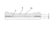
The light-
なお、光透過性カバー部材3の画像表示部側表面の周縁部には、表示画像の輝度やコントラスト向上のために遮光層5が設けられている。遮光層5は、黒色等に着色された塗料をスクリーン印刷法などで塗布し、乾燥・硬化させたものである。遮光層5の厚みとしては、通常5〜100μmである。
A
[貼合樹脂材]
硬化樹脂層4を構成する光硬化性樹脂組成物6は、透明で、紫外線若しくは可視光で硬化が可能な光硬化性樹脂を好適に用いることができる。光硬化性樹脂組成物6は、液晶表示装置1の透過率を低減させないように、硬化後の400nm以上の光透過率が90%以上であるもの選択することが望ましい。また、光硬化性樹脂組成物6は、モノマー、重合開始剤、粘度調整のためのポリマーからなる光硬化性樹脂を含有する。
[Laminating resin material]
As the photocurable resin composition 6 that constitutes the cured
光硬化性樹脂組成物6は液状、ゲル状等のいずれの性状であってもよいが、好ましくは液状である。光硬化性樹脂組成物6が液状であることにより、例えば後述する画像表示装置1の製造方法において、遮光層5と光透過性カバー部材3の遮光層形成側表面とで形成される段差をより確実にキャンセルすることができる。ここで、光硬化性樹脂組成物6が液状であるとは、B型粘度計で測定した25℃における粘度が0.01〜100Pa・sを示すことが好ましい。
The photocurable resin composition 6 may be in any form such as liquid or gel, but is preferably liquid. Since the photocurable resin composition 6 is in a liquid state, for example, in a method of manufacturing the
また、硬化樹脂層4は、光硬化性樹脂組成物6がシート状に成型された光学粘着シート(OCA: Optical Clear Adhesive)により構成されてもよい。光学粘着シートは、例えば離型処理されたポリエチレンテレフテレート等の基材に光硬化性樹脂組成物6を塗布、乾燥して粘着剤層を形成し、必要に応じて架橋反応させることにより製造される。
The cured
光硬化性樹脂組成物6の一例を説明する。本実施の形態に係る光硬化性樹脂組成物6は、光ラジカル重合性ポリ(メタ)アクリレート(成分(a))と、光ラジカル重合性(メタ)アクリレート(成分(b))と、液状可塑剤(成分(c))、又は粘着付与剤(成分(d))からなる柔軟剤と、光重合開始剤(成分(e))とを含有する。なお、本明細書において、(メタ)アクリレートとは、アクリル酸エステル(アクリレート)とメタクリル酸エステル(メタクリレート)とを包含する意味である。 An example of the photocurable resin composition 6 will be described. The photocurable resin composition 6 according to the present embodiment includes a photoradical-polymerizable poly (meth) acrylate (component (a)), a photoradical-polymerizable (meth) acrylate (component (b)), and a liquid plastic. It contains a softening agent consisting of an agent (component (c)) or a tackifier (component (d)), and a photopolymerization initiator (component (e)). In addition, in this specification, (meth) acrylate is meant to include an acrylic acid ester (acrylate) and a methacrylic acid ester (methacrylate).
[成分(a)]
光ラジカル重合性ポリ(メタ)アクリレート(成分(a))の好ましい具体例としては、ポリウレタン、ポリイソプレン、ポリブタジエン等を骨格に持つ(メタ)アクリレート系オリゴマーを挙げることができる。ポリウレタン骨格を持つ(メタ)アクリル系オリゴマーの好ましい具体例としては、脂肪族ウレタンアクリレート(EBECRYL230(分子量5000)、ダイセル・サイテック社;UA−1、ライトケミカル社)等を挙げることができる。また、ポリイソプレン骨格の(メタ)アクリレートオリゴマーの好ましい具体例としては、ポリイソプレン重合体の無水マレイン酸付加物と2−ヒドロキシエチルメタクリレートとのエステル化物(UC102(ポリスチレン換算分子量17000)、(株)クラレ;UC203(ポリスチレン換算分子量35000)、(株)クラレ;UC−1(分子量約25000)、(株)クラレ)等を挙げることができる。
[Component (a)]
Specific preferred examples of the photo-radical-polymerizable poly (meth) acrylate (component (a)) include (meth) acrylate-based oligomers having skeletons such as polyurethane, polyisoprene and polybutadiene. Specific preferred examples of the (meth) acrylic oligomer having a polyurethane skeleton include aliphatic urethane acrylate (EBECRYL230 (molecular weight 5000), Daicel Cytec Co., Ltd .; UA-1, Light Chemical Co.) and the like. Moreover, as a preferable specific example of the (meth) acrylate oligomer having a polyisoprene skeleton, an esterified product of a maleic anhydride adduct of a polyisoprene polymer and 2-hydroxyethyl methacrylate (UC102 (polystyrene-equivalent molecular weight 17,000), (Ltd.) Kuraray; UC203 (polystyrene-equivalent molecular weight 35,000), Kuraray Co., Ltd .; UC-1 (molecular weight about 25,000), Kuraray Co., Ltd., and the like.
[成分(b)]
光ラジカル重合性(メタ)アクリレート(成分(b))の好ましい具体例としては、2−ヒドロキシプロピル(メタ)アクリレート、ベンジルアクリレート、ジシクロペンテニルオキシエチル(メタ)アクリレート、イソボルニル(メタ)アクリレート、オクチル(メタ)アクリレート等を挙げることができる。
[Component (b)]
Specific preferred examples of the photo-radical-polymerizable (meth) acrylate (component (b)) include 2-hydroxypropyl (meth) acrylate, benzyl acrylate, dicyclopentenyloxyethyl (meth) acrylate, isobornyl (meth) acrylate, octyl. (Meth) acrylate etc. can be mentioned.
[成分(c)]
液状可塑成分(成分(c))は、紫外線照射によりそれ自身は光硬化をせず、光硬化後の硬化樹脂層あるいは仮硬化樹脂層に柔軟性を与え、また硬化樹脂層間あるいは仮硬化樹脂層の硬化収縮率を低減させるものである。このような液状可塑成分としては、液状のポリブタジエン系可塑剤、ポリイソプレン系可塑剤、フタル酸エステル系可塑剤及びアジピン酸エステル系可塑剤からなる群から選択される少なくも一種を挙げることができる。
[Component (c)]
The liquid plastic component (component (c)) itself does not photo-cure by irradiation with ultraviolet rays, and imparts flexibility to the cured resin layer or the temporary-cured resin layer after the photo-curing, or the cured resin layer or the temporarily cured resin layer. It is intended to reduce the curing shrinkage rate of. Examples of such a liquid plastic component include at least one selected from the group consisting of liquid polybutadiene plasticizers, polyisoprene plasticizers, phthalate ester plasticizers and adipic ester plasticizers. ..
[成分(d)]
粘着付与剤(タッキファイア)(成分(d))は、成分(c)と同様、光硬化後の硬化樹脂層あるいは仮硬化樹脂層に柔軟性を与えるとともに、光硬化性樹脂組成物6から形成された硬化樹脂層又は仮硬化樹脂層の初期接着強度(いわゆるタック性)を向上させる。粘着付与剤としては、例えば、テルペン樹脂、テルペンフェノール樹脂、水素添加テルペン樹脂等のテルペン系樹脂、天然ロジン、重合ロジン、ロジンエステル、水素添加ロジン等のロジン樹脂、ポリブタジエン、ポリイソプレン等の石油樹脂などを使用することができる。柔軟剤としては、成分(c)又は成分(d)の少なくともいずれか一方が含まれていればよい。
[Component (d)]
Like the component (c), the tackifier (tackifier) (component (d)) imparts flexibility to the cured resin layer or the temporarily cured resin layer after photocuring, and is formed from the photocurable resin composition 6. The initial adhesive strength (so-called tackiness) of the cured resin layer or temporary cured resin layer thus obtained is improved. As the tackifier, for example, terpene resin, terpene phenol resin, terpene resin such as hydrogenated terpene resin, natural rosin, polymerized rosin, rosin ester, rosin resin such as hydrogenated rosin, polybutadiene, petroleum resin such as polyisoprene Etc. can be used. The softening agent may include at least one of the component (c) and the component (d).
[成分(e)]
光重合開始剤(成分(e))としては、例えば、1−ヒドロキシ−シクロへキシルフェニルケトン(イルガキュア184、BASFジャパン(株))、2−ヒドロキシ−1−{4−[4−(2一ヒドロキシ−2−メチル−プロピロニル)ベンジル]フェニル}−2−メチル−1−プロパン−1−オン(イルガキュア127、BASFジャパン(株))、ベンゾフェノン、アセトフェノン等を挙げることができる。
[Component (e)]
Examples of the photopolymerization initiator (component (e)) include 1-hydroxy-cyclohexyl phenyl ketone (IRGACURE 184, BASF Japan Ltd.), 2-hydroxy-1- {4- [4- (21 Hydroxy-2-methyl-propionyl) benzyl] phenyl} -2-methyl-1-propan-1-one (Irgacure 127, BASF Japan Ltd.), benzophenone, acetophenone and the like can be mentioned.
光重合開始剤の添加量は、少なすぎると紫外線照射時に硬化不足となり、多すぎると開裂によるアウトガスが増え発泡不具合の傾向があるので、光ラジカル重合性ポリ(メタ)アクリレート100質量部に対し、好ましくは0.1〜10質量部、より好ましくは0.2〜5質量部である。 If the amount of the photopolymerization initiator added is too small, curing becomes insufficient at the time of irradiation with ultraviolet rays, and if it is too large, outgas due to cleavage increases and there is a tendency for foaming problems. It is preferably 0.1 to 10 parts by mass, more preferably 0.2 to 5 parts by mass.
なお、光硬化性樹脂組成物6には、上述した成分(a)〜成分(e)に加えて、本発明の効果を損なわない範囲で種々の添加剤を配合することができる。例えば、硬化樹脂の分子量の調整のために連鎖移動剤、例えば、2−メルカプトエタノール、ラウリルメルカプタン、グリシジルメルカプタン、メルカプト酢酸、チオグリコール酸2−エチルヘキシル、2,3−ジメチルカプト−1−プロパノール、α−メチルスチレンダイマー等を配合することができる。その他にも、必要に応じて、シランカップリング剤等の接着改善剤、酸化防止剤、紫外線吸収剤等の添加剤を含有することができる。このような光硬化性樹脂組成物6は、上述した成分(a)〜成分(e)と、必要に応じて添加される各種添加剤とを、公知の混合手法に従って均一に混合することにより調製することができる。これらの添加剤の添加量は、所望する物性が得られるように適宜設定することができる。なお、光硬化性樹脂組成物の市販品としては、例えば商品名「LCR1000−DM」「HSVR600」「HSVR330」(いずれもデクセリアルズ(株))などが挙げられる。 In addition to the components (a) to (e) described above, various additives can be added to the photocurable resin composition 6 as long as the effects of the present invention are not impaired. For example, a chain transfer agent for controlling the molecular weight of the cured resin, for example, 2-mercaptoethanol, lauryl mercaptan, glycidyl mercaptan, mercaptoacetic acid, 2-ethylhexyl thioglycolate, 2,3-dimethylcapto-1-propanol, α -Methylstyrene dimer and the like can be added. In addition, if necessary, additives such as an adhesion improver such as a silane coupling agent, an antioxidant, and an ultraviolet absorber can be contained. Such a photocurable resin composition 6 is prepared by uniformly mixing the above-mentioned components (a) to (e) and various additives added as necessary according to a known mixing method. can do. The addition amount of these additives can be appropriately set so as to obtain desired physical properties. Examples of commercial products of the photocurable resin composition include trade names “LCR1000-DM”, “HSVR600”, “HSVR330” (all of Dexerials Co., Ltd.) and the like.
[接合体の製造工程]
次いで、光硬化性樹脂組成物6を用いて画像表示部材2に光透過性カバー部材3を貼り合せて画像表示装置1を製造する工程について説明する。先ず、真空雰囲気下で、第1の貼合プレート11に支持された画像表示部材2と第2の貼合プレート12に支持された光透過性カバー部材3とを、光硬化性樹脂組成物6を介して所定の貼合圧力で貼り合わせる。
[Manufacturing process of bonded body]
Next, a process of manufacturing the
具体的に、図2に示すように、片面の周縁部に形成された遮光層5を有する光透過性カバー部材3を用意し、図3に示すように、光透過性カバー部材3の遮光層5が設けられた表面3aに、液状の光硬化性樹脂組成物6を塗布し、光硬化性樹脂層7を形成する。ここで、液状とは、B型粘度計で0.01〜100Pa.s(25℃)の粘度を示すものである。
Specifically, as shown in FIG. 2, a light-transmitting
また、この塗布工程では、液状の光硬化性樹脂組成物6を遮光層5の厚さよりも厚く塗布することが好ましい。光硬化性樹脂組成物6を遮光層5の厚さよりも厚く塗布することにより、後述する貼合工程において、光透過性カバー部材3と遮光層5との間に厚み方向に段差がある場合でも、仮硬化された光硬化性樹脂組成物6の柔らかい内部が当該段差を吸収するため、貼合性を向上させることができる。なお、光硬化性樹脂組成物6の塗布は、必要な厚みが得られるように複数回行ってもよい。
In addition, in this coating step, it is preferable that the liquid photocurable resin composition 6 is coated thicker than the
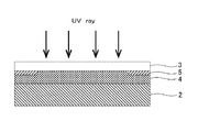
次に、図4に示すように、光硬化性樹脂組成物6に対して紫外線を照射し、光硬化性樹脂組成物6を仮硬化させて仮硬化樹脂層8を形成する。これにより仮硬化樹脂層8は、表面に薄膜が形成される。仮硬化樹脂層8表面の反応率は60〜80%以上であることが好ましい。これにより、仮硬化樹脂層8全体の弾性率を貼り合わせ可能な低弾性率に維持しながら、次の貼合工程におけるはみ出しを抑制し、貼合性を向上させることができる。
Next, as shown in FIG. 4, the photocurable resin composition 6 is irradiated with ultraviolet rays to temporarily cure the photocurable resin composition 6 to form a temporary cured
次いで、図5に示すように、チャンバー10内に画像表示部材2及び光透過性カバー部材3を配置する。チャンバー10は、第1、第2の貼合プレート11,12が、図示しない昇降機構により、互いに近接離間可能に設けられている。画像表示部材2は、第1の貼合プレート11に表示部を上向きにして支持される。また、光透過性カバー部材3は、第2の貼合プレート12に仮硬化樹脂層8が形成された表面3aを下側に向けて画像表示部材2の表示部と対向されて支持される。
Next, as shown in FIG. 5, the
なお、第1、第2の貼合プレート11,12は、一方がメタルプレートであり、他方が粘着性を有するゴムプレートであり、メタルプレートに支持された貼合部材に対してゴムプレートに支持された貼合部材側がアライメント調整を図る。また、第1、第2の貼合プレート11,12は、真空吸着あるいはメカチャックにより貼合部材を支持する。その他、第1、第2の貼合プレート11,12は、公知の材質、支持方法を採用することができる。
One of the first and
[貼合工程]
次に、チャンバー10内の空気をポンプなどで排気し、所定の真空雰囲気とした後、図6に示すように、第1の貼合プレート11を上昇させること等により第1、第2の貼合プレート11,12を近接させ、画像表示部材2と光透過性カバー部材3の仮硬化樹脂層8が形成された表面3aとを、所定の圧力及び所定の時間だけ貼り合わせる。また、貼り合わせ温度は、適宜設定されるが、例えば10℃〜80℃とされる。
[Laminating process]
Next, the air in the
仮硬化樹脂層8は、表面に薄膜が形成されているため、天地逆転した際の未硬化樹脂の流れ落ちを防ぐことができる。また、仮硬化樹脂層8上面の周縁部には、遮光層5及び表面張力による微小な凹凸が生じることがあるが、仮硬化樹脂層8の内部が液状に近い状態であるため、仮硬化樹脂層8を押し込むことができる。
Since the thin film is formed on the surface of the temporarily cured
また、真空雰囲気下で画像表示部材2と光透過性カバー部材3との間に仮硬化樹脂層8を押し込むことにより、気泡の混入を防止することができる。また、仮硬化樹脂層8の押し込みにより仮硬化樹脂層8表面の薄膜が画像表示部材2表面に追従するため、気泡の発生を抑制するとともに微小な凹凸を平坦化させることができる。
Further, by pushing the temporarily cured
[減圧工程]
貼り合せ開始から所定時間が経過した後、第1の貼合プレート11を下降させる等により第1、第2の貼合プレート11,12を若干離間させ、画像表示部材2と光透過性カバー部材3とが第1、第2の貼合プレート11,12に挟持された状態で貼合圧力を減じる。これにより、画像表示部材2と光透過性カバー部材3とに掛かる貼合圧力が低減される。
[Decompression process]
After a lapse of a predetermined time from the start of bonding, the first and
減圧の程度としては、第1、第2の貼合プレート11,12が画像表示部材2と光透過性カバー部材3とを挟持している状態を維持できる範囲であればよく、例えば貼合工程における所定の貼合圧力に対し5〜60%減圧してもよい。なお、減圧の程度は、仮硬化樹脂層8の弾性率によって第1、第2の貼合プレート11,12の離間距離に対する減圧率は異なるため、使用する光硬化性樹脂組成物6に応じて所定の減圧率となるように第1、第2の貼合プレート11,12の離間距離を適宜設定する。
The degree of decompression may be within a range in which the state where the first and
また、液状の光硬化性樹脂組成物6を用いた場合、弾性率(Pa)を正確に測定することは困難であるため、減圧の程度は第1、第2の貼合プレート11,12の離間距離により定める。すなわち、減圧の程度としては、第1、第2の貼合プレート11,12が画像表示部材2と光透過性カバー部材3とを挟持している状態を維持できる範囲であり、例えば第1の貼合プレート及び第2の貼合プレートを、5〜50μm離間させる。
Further, when the liquid photocurable resin composition 6 is used, it is difficult to accurately measure the elastic modulus (Pa), and therefore the degree of decompression depends on the first and
[大気開放工程]
次いで、チャンバー10内の雰囲気を大気圧にする。このとき、本技術によれば、画像表示部材2と光透過性カバー部材3とは、第1、第2の貼合プレート11,12によってそれぞれチャッキングされるとともに第1、第2の貼合プレート11,12によって挟持された状態が維持されているため、画像表示部材2と光透過性カバー部材3との貼合位置にズレが生じることを防止することができる。したがって、大気開放時間を短くすることにより、チャンバー10内に急激な圧力変動や乱気流が発生した場合にも、画像表示部材2と光透過性カバー部材3との貼合位置ズレが防止でき、画像表示装置1の製造タクトを短縮することができる。
[Open to atmosphere]
Next, the atmosphere in the
[貼合圧力の解除工程]
次いで、図7に示すように、第2の貼合プレート12による光透過性カバー部材3のチャッキングを解除するとともに第1の貼合プレート11をさらに下降させる等により第1、第2の貼合プレート11,12を完全に離間させ、画像表示部材2と光透過性カバー部材3とに対する貼合圧力を解除する。
[Laminating pressure release process]
Then, as shown in FIG. 7, the chucking of the light-
[本硬化工程]
その後、図8に示すように、画像表示部材2と光透過性カバー部材3との接合体に対して、さらに紫外線を照射することにより、仮硬化樹脂層8を本硬化させる。これにより、画像表示部材2と光透過性カバー部材3とを光透過性の硬化樹脂層4を介して接合させた画像表示装置1(図1)を得る。さらに必要に応じて、光透過性カバー部材3の遮光層5と画像表示部材2との間の仮硬化樹脂層8に紫外線を照射し、仮硬化樹脂層8を本硬化させてもよい。
[Main curing step]
Thereafter, as shown in FIG. 8, the provisionally cured
なお、本硬化工程において、光硬化性樹脂組成物6の反応率は、90%以上であることが好ましく、95%以上であることがより好ましい。光硬化性樹脂組成物6を十分に硬化させることにより、光透過性カバー部材3と画像表示部材2との接着力を向上させることができる。
In the main curing step, the reaction rate of the photocurable resin composition 6 is preferably 90% or higher, more preferably 95% or higher. By sufficiently curing the photocurable resin composition 6, the adhesive force between the light
[本技術の効果]
本技術が適用された接合体の製造工程によれば、画像表示部材2と光透過性カバー部材3とが第1、第2の貼合プレート11,12に挟持された状態で貼合圧力を減じ、この状態で大気開放を行う。したがって、光透過性樹脂組成物6が液状やゲル状であった場合でも光透過性カバー部材3と画像表示部材2との貼合位置ズレを防止することができる。
[Effect of this technology]
According to the manufacturing process of the joined body to which the present technology is applied, the bonding pressure is applied in a state where the
また、光透過性カバー部材3と画像表示部材2とが第1、第2の貼合プレート11,12に挟持されているため、大気開放時間を短縮しチャンバー10内の急激な圧力変動や乱気流が生じた場合にも貼合位置ズレが防止されることから、製造タクトの短縮化を図ることができる。
Further, since the light-
さらに、画像表示部材2と光透過性カバー部材3との貼合圧力を減圧した状態で大気開放を行うため、大気開放が終了するまで第1、第2の貼合プレート11,12に挟持させていても、画像表示部材2と光透過性カバー部材3とに貼合圧力が過剰に掛かることがない。したがって、本技術が適用された製造工程により製造された画像表示装置1は、硬化樹脂層4に残存応力が局所的に介在することがなく、硬化樹脂層4の応力ムラに起因する色ムラの発生を防止することができる。また、薄型化が進展している画像表示部材2や光透過性カバー部材3に対する負荷も低減でき、反りや損傷を防止することができる。
Further, since the air is released to the atmosphere while the pressure for bonding the
なお、上記では、光透過性カバー部材3に光硬化性樹脂組成物6を塗布し、仮硬化させた後、天地を逆転して第2の貼合プレート12に支持させたが、第1の貼合プレートに支持された画像表示部材2又は光透過性カバー部材3に液状の光硬化性樹脂組成物6を塗布し、仮硬化させずに貼り合せ、その後、光硬化させてもよい。
In the above description, the light-curable resin composition 6 was applied to the light-
また、液状又はゲル状の光硬化性樹脂組成物6を用いる他、光硬化性樹脂組成物6がシート状に成型された光学粘着シートを用いてもよい。光学粘着シートは、成型過程でタック性を備え、画像表示部材2と光透過性カバー部材3との貼合位置は保持できるが、本技術が適用された接合体の製造工程に適用すれば、画像表示部材2及び光透過性カバー部材3を第1、第2の貼合プレート11,12間に挟持させた状態で貼合圧力を減じて大気開放を行うことにより、貼合位置ズレを確実に防止できるとともに、画像表示部材2及び光透過性カバー部材3に対して貼合圧力が過剰に掛かることを防止することができる。
Further, in addition to using the liquid or gel photocurable resin composition 6, an optical adhesive sheet in which the photocurable resin composition 6 is molded into a sheet may be used. The optical pressure-sensitive adhesive sheet has tackiness during the molding process and can hold the bonding position between the
次いで、本技術の実施例について説明する。本実施例では、液晶表示パネルとカバーガラスとを光硬化性樹脂組成物を介して真空雰囲気下で接続し、大気開放した後のズレ量を測定した。カバーガラスは、厚さ0.7mm、5inchサイズのものを使用した。また、各実施例及び比較例に係る液晶表示パネルとカバーガラスとの接続体のサンプル数は10個とした。 Next, examples of the present technology will be described. In this example, the liquid crystal display panel and the cover glass were connected via a photocurable resin composition in a vacuum atmosphere, and the amount of deviation after opening to the atmosphere was measured. The cover glass used had a thickness of 0.7 mm and a size of 5 inches. Further, the number of samples of the connected body of the liquid crystal display panel and the cover glass according to each of the examples and the comparative examples was set to 10.
[実施例1]
実施例1では、貼合樹脂材として液状の光学弾性樹脂(LCR1000−DM、液粘度4200mPa・sec;デクセリアルズ株式会社製)を使用した。この液状の光学弾性樹脂をカバーガラスに塗布し、チャンバー内において真空雰囲気下で機械的にカバーガラスとのギャップ及び樹脂厚を制御しながら液晶表示パネルを載置して貼り合せた。光学弾性樹脂の塗布厚みは100μm、チャンバー内の真空度は50Paとした。
[Example 1]
In Example 1, a liquid optical elastic resin (LCR1000-DM, liquid viscosity 4200 mPa · sec; manufactured by Dexerials Co., Ltd.) was used as the bonding resin material. This liquid optically elastic resin was applied to a cover glass, and a liquid crystal display panel was placed and bonded together while mechanically controlling the gap with the cover glass and the resin thickness in a vacuum atmosphere in a chamber. The coating thickness of the optical elastic resin was 100 μm, and the degree of vacuum in the chamber was 50 Pa.
貼り合せ後、液晶表示パネルを支持する貼合プレートとカバーガラスを支持する貼合プレートと間の距離を5μm離間させ、光学弾性樹脂を介して貼り合わされた液晶表示パネルとカバーガラスとが一対の貼合プレート間に挟持された状態で貼合圧力を減じ、この状態で大気開放を行った。大気開放時間は1秒とした。 After the bonding, the distance between the bonding plate supporting the liquid crystal display panel and the bonding plate supporting the cover glass is set to 5 μm, and the liquid crystal display panel and the cover glass bonded together via the optical elastic resin form a pair. The laminating pressure was reduced while being sandwiched between the laminating plates, and the atmosphere was opened in this state. The atmospheric opening time was 1 second.
大気開放後に、貼合プレートによる液晶表示パネル及びカバーガラスの支持を解除するとともに、一対の貼合プレートを離間させて液晶表示パネル及びカバーガラスの接合体に掛かる貼合圧力を完全に解除し、液晶表示パネルとカバーガラスとの位置ズレ量を測定したところ、ズレは生じなかった。 After opening to the atmosphere, the supporting of the liquid crystal display panel and the cover glass by the bonding plate is released, and the bonding pressure applied to the bonded body of the liquid crystal display panel and the cover glass is completely released by separating the pair of bonding plates. When the positional deviation amount between the liquid crystal display panel and the cover glass was measured, no deviation occurred.
[実施例2]
実施例2では、貼合樹脂材として液状の光学弾性樹脂(HSVR330;デクセリアルズ株式会社製)を使用した。この液状の光学弾性樹脂をカバーガラスに塗布し、紫外線を照射することにより仮硬化させ、仮硬化樹脂層を形成した。次いで、チャンバー内において真空雰囲気下で液晶表示パネルと貼り合せた。光学弾性樹脂の塗布厚みは100μm、仮硬化樹脂層の弾性率は1.60E+4(Pa)、チャンバー内の真空度は50Pa、貼り合せの推力は500Nとした。
[Example 2]
In Example 2, a liquid optical elastic resin (HSVR330; manufactured by Dexerials Co., Ltd.) was used as the bonding resin material. This liquid optical elastic resin was applied to a cover glass and was temporarily cured by irradiating with ultraviolet rays to form a temporarily cured resin layer. Then, it was attached to a liquid crystal display panel in a chamber under a vacuum atmosphere. The coating thickness of the optical elastic resin was 100 μm, the elastic modulus of the temporarily cured resin layer was 1.60E + 4 (Pa), the degree of vacuum in the chamber was 50 Pa, and the thrust of bonding was 500 N.
貼り合せ後、液晶表示パネルを支持する貼合プレートとカバーガラスを支持する貼合プレートと間の距離を離間させ、液晶表示パネルとカバーガラスとが一対の貼合プレート間に挟持された状態で貼合圧力を30%減じ、この状態で大気開放を行った。大気開放時間は1秒とした。 After bonding, the bonding plate supporting the liquid crystal display panel and the bonding plate supporting the cover glass are separated from each other with the liquid crystal display panel and the cover glass sandwiched between the pair of bonding plates. The bonding pressure was reduced by 30%, and the atmosphere was opened in this state. The atmospheric opening time was 1 second.
大気開放後に、貼合プレートによる液晶表示パネル及びカバーガラスの支持を解除するとともに、一対の貼合プレートを離間させて液晶表示パネル及びカバーガラスの接合体に掛かる貼合圧力を完全に解除し、液晶表示パネルとカバーガラスとの位置ズレ量を測定したところ、ズレは生じなかった。 After opening to the atmosphere, the supporting of the liquid crystal display panel and the cover glass by the bonding plate is released, and the bonding pressure applied to the bonded body of the liquid crystal display panel and the cover glass is completely released by separating the pair of bonding plates. When the positional deviation amount between the liquid crystal display panel and the cover glass was measured, no deviation occurred.
[実施例3]
実施例3では、貼合樹脂材として液状の光学弾性樹脂(HSVR600;デクセリアルズ株式会社製)を使用した。この液状の光学弾性樹脂をカバーガラスに塗布し、紫外線を照射することにより仮硬化させ、仮硬化樹脂層を形成した。次いで、チャンバー内において真空雰囲気下で液晶表示パネルと貼り合せた。光学弾性樹脂の塗布厚みは100μm、仮硬化樹脂層の弾性率は5.10E+4(Pa)、チャンバー内の真空度は50Pa、貼り合せの推力は500Nとした。
[Example 3]
In Example 3, a liquid optical elastic resin (HSVR600; manufactured by Dexerials Co., Ltd.) was used as the bonding resin material. This liquid optical elastic resin was applied to a cover glass and was temporarily cured by irradiating with ultraviolet rays to form a temporarily cured resin layer. Then, it was attached to a liquid crystal display panel in a chamber under a vacuum atmosphere. The coating thickness of the optical elastic resin was 100 μm, the elastic modulus of the temporarily cured resin layer was 5.10E + 4 (Pa), the degree of vacuum in the chamber was 50 Pa, and the thrust of bonding was 500 N.
貼り合せ後、液晶表示パネルを支持する貼合プレートとカバーガラスを支持する貼合プレートと間の距離を離間させ、液晶表示パネルとカバーガラスとが一対の貼合プレート間に挟持された状態で貼合圧力を30%減じ、この状態で大気開放を行った。大気開放時間は1秒とした。 After bonding, the bonding plate supporting the liquid crystal display panel and the bonding plate supporting the cover glass are separated from each other with the liquid crystal display panel and the cover glass sandwiched between the pair of bonding plates. The bonding pressure was reduced by 30%, and the atmosphere was opened in this state. The atmospheric opening time was 1 second.
大気開放後に、貼合プレートによる液晶表示パネル及びカバーガラスの支持を解除するとともに、一対の貼合プレートを離間させて液晶表示パネル及びカバーガラスの接合体に掛かる貼合圧力を完全に解除し、液晶表示パネルとカバーガラスとの位置ズレ量を測定したところ、ズレは生じなかった。 After opening to the atmosphere, the supporting of the liquid crystal display panel and the cover glass by the bonding plate is released, and the bonding pressure applied to the bonded body of the liquid crystal display panel and the cover glass is completely released by separating the pair of bonding plates, When the positional deviation amount between the liquid crystal display panel and the cover glass was measured, no deviation occurred.
[比較例1]
比較例1では、貼り合せ後、貼合プレートによるカバーガラスの支持を解除し、一対の貼合プレートを離間させて液晶表示パネル及びカバーガラスの接合体に掛かる貼合圧力を完全に解除した後に大気開放を行った。その他の条件は実施例1と同じである。
[Comparative Example 1]
In Comparative Example 1, after the bonding, the support of the cover glass by the bonding plate is released, the pair of bonding plates are separated, and the bonding pressure applied to the bonded body of the liquid crystal display panel and the cover glass is completely released. The atmosphere was released. Other conditions are the same as in Example 1.
比較例1では、液晶表示パネルとカバーガラスとの位置ズレ量を測定したところ、0.5〜3mmのズレが生じた。 In Comparative Example 1, when the positional deviation amount between the liquid crystal display panel and the cover glass was measured, a deviation of 0.5 to 3 mm occurred.
[比較例2]
比較例2では、貼り合せ後、貼合プレートによるカバーガラスの支持を解除し、一対の貼合プレートを離間させて液晶表示パネル及びカバーガラスの接合体に掛かる貼合圧力を完全に解除した後に大気開放を行った。その他の条件は実施例2と同じである。
[Comparative example 2]
In Comparative Example 2, after the bonding, the support of the cover glass by the bonding plate is released, the pair of bonding plates are separated, and the bonding pressure applied to the bonded body of the liquid crystal display panel and the cover glass is completely released. The atmosphere was released. The other conditions are the same as in Example 2.
比較例2では、液晶表示パネルとカバーガラスとの位置ズレ量を測定したところ、0.03〜0.3mmのズレが生じた。 In Comparative Example 2, when the positional shift amount between the liquid crystal display panel and the cover glass was measured, a shift of 0.03 to 0.3 mm occurred.
[比較例3]
比較例3では、貼り合せ後、貼合プレートによるカバーガラスの支持を解除し、一対の貼合プレートを離間させて液晶表示パネル及びカバーガラスの接合体に掛かる貼合圧力を完全に解除した後に大気開放を行った。その他の条件は実施例3と同じである。
[Comparative Example 3]
In Comparative Example 3, after the bonding, the support of the cover glass by the bonding plate is released, the pair of bonding plates are separated, and the bonding pressure applied to the bonded body of the liquid crystal display panel and the cover glass is completely released. The atmosphere was released. The other conditions are the same as in Example 3.
比較例3では、液晶表示パネルとカバーガラスとの位置ズレ量を測定したところ、0.03〜0.1mmのズレが生じた。 In Comparative Example 3, when the positional shift amount between the liquid crystal display panel and the cover glass was measured, a shift of 0.03 to 0.1 mm occurred.
[比較例4]
比較例4では、貼り合せ後、大気開放が終了するまで液晶表示パネル及びカバーガラスの接合体に貼合圧力を掛け続け、その後貼合プレートによる液晶表示パネル及びカバーガラスの支持を解除するとともに、一対の貼合プレートを離間させて液晶表示パネル及びカバーガラスの接合体に掛かる貼合圧力を完全に解除した。その他の条件は実施例2と同じである。
[Comparative Example 4]
In Comparative Example 4, after bonding, the bonding pressure of the liquid crystal display panel and the cover glass is continuously applied to the bonded body of the liquid crystal display panel and the cover glass until the release to the atmosphere is finished, and thereafter, the support of the liquid crystal display panel and the cover glass by the bonding plate is released, The pair of bonding plates were separated from each other to completely release the bonding pressure applied to the bonded body of the liquid crystal display panel and the cover glass. The other conditions are the same as in Example 2.
比較例4では、液晶表示パネルとカバーガラスとの位置ズレ量を測定したところ、ズレは生じなかったが、接合体に反りが生じた。 In Comparative Example 4, when the positional deviation amount between the liquid crystal display panel and the cover glass was measured, no deviation occurred, but the bonded body warped.

表1に示すように、実施例1〜3では、液晶表示パネルとカバーガラスとが一対の貼合プレート間に挟持された状態で貼合圧力を減じ、この状態で大気開放を行っているため、1秒という短時間で大気開放を行い、チャンバー内に急激な圧力変動や乱気流が発生したにも関わらず、液晶表示パネルとカバーガラスとの貼合位置ズレを防止することができた。 As shown in Table 1, in Examples 1 to 3, the bonding pressure was reduced in a state where the liquid crystal display panel and the cover glass were sandwiched between the pair of bonding plates, and the atmosphere was opened in this state. It was possible to prevent displacement of the bonding position between the liquid crystal display panel and the cover glass in spite of sudden pressure fluctuation and turbulent air flow in the chamber by opening to the atmosphere in a short time of 1 second.
また、大気開放に先立って貼合圧力を減じていることから、大気開放後に貼合圧力を解除しても、接合体に反りが生じることなく、液晶表示パネルやカバーガラスに損傷を与える恐れもない。 In addition, since the bonding pressure is reduced prior to opening to the atmosphere, even if the bonding pressure is released after opening to the atmosphere, the bonded body will not warp and the liquid crystal display panel and cover glass may be damaged. Absent.
一方、比較例1〜3は、液晶表示パネル及びカバーガラスに対する貼合圧力を解除した後に大気開放を行ったため、短時間の大気開放によって生じたチャンバー内の急激な圧力変動や乱気流により、液晶表示パネルとカバーガラスとの貼合位置ズレが生じた。比較例1では、液状の光学弾性樹脂を介在させていたため、光学弾性樹脂を仮硬化させた比較例2、比較例3と比べて位置ズレ量が大きくなった。 On the other hand, in Comparative Examples 1 to 3, since the bonding pressure to the liquid crystal display panel and the cover glass was released and then the atmosphere was opened, the liquid crystal display was caused by the rapid pressure fluctuation and turbulence in the chamber caused by the short time atmosphere opening. The bonding position of the panel and the cover glass was misaligned. In Comparative Example 1, since the liquid optical elastic resin was interposed, the positional deviation amount was larger than in Comparative Examples 2 and 3 in which the optical elastic resin was temporarily cured.
また、比較例4は、貼り合せから大気開放が終了するまで液晶表示パネル及びカバーガラスに貼合圧力を掛けていたため、大気開放による位置ズレは防止できたが、液晶表示パネル及びカバーガラスに貼合圧力が過剰に掛かり、反りが発生した。 Further, in Comparative Example 4, since the bonding pressure was applied to the liquid crystal display panel and the cover glass from the bonding to the end of opening to the atmosphere, displacement due to opening to the atmosphere could be prevented, but bonding to the liquid crystal display panel and the cover glass was prevented. The combined pressure was excessive and warpage occurred.
1 画像表示装置、2 画像表示部材、3 光透過性カバー部材、4 硬化樹脂層、5 遮光層、6 光硬化性樹脂組成物、7 光硬化性樹脂層、8 仮硬化樹脂層、10 チャンバー、11 第1の貼合プレート、12 第2の貼合プレート
DESCRIPTION OF
Claims (7)
次いで、上記第1、第2の貼合部材が上記第1、第2の貼合プレートに挟持された状態で上記第1、第2の貼合プレートを離間させて、上記貼合圧力を減じる工程と、
次いで、真空雰囲気下から大気圧へ開放する工程と、
次いで、上記第1、第2の貼合部材に対する貼合圧力を解除する工程とを有する接合体の製造方法。 Under a vacuum atmosphere, the first bonding member supported by the first bonding plate and the second bonding member supported by the second bonding plate are separated by a predetermined amount through a bonding resin material. The process of bonding with bonding pressure,
Next, the first and second bonding members are separated from each other while the first and second bonding members are sandwiched between the first and second bonding plates to reduce the bonding pressure. Process,
Then, a step of opening from a vacuum atmosphere to atmospheric pressure,
Next, a method of manufacturing a joined body, including a step of releasing the bonding pressure applied to the first and second bonding members.
上記第1、第2の貼合部材に対する貼合圧力を減じる工程において、所定の上記貼合圧力に対し5〜60%減じる請求項1又は2に記載の接合体の製造方法。 The above-mentioned laminated resin material is provisionally cured,
The method for manufacturing a joined body according to claim 1, wherein in the step of reducing the bonding pressure to the first and second bonding members, the bonded pressure is reduced by 5 to 60% with respect to the predetermined bonding pressure.
上記第1、第2の貼合部材に対する貼合圧力を減じる工程において、上記第1の貼合プレート及び上記第2の貼合プレートを、5〜50μm離間させる請求項1〜3のいずれか1項に記載の接合体の製造方法。 The above-mentioned laminated resin material is liquid,
The step of reducing the bonding pressure to the first and second bonding members, wherein the first bonding plate and the second bonding plate are separated by 5 to 50 μm. A method for manufacturing a joined body according to item.
次いで、上記第1、第2の貼合部材が上記第1、第2の貼合プレートに挟持された状態で上記第1、第2の貼合プレートを離間させて、貼合圧力を減じる工程と、
次いで、真空雰囲気下から大気圧へ開放する工程と、
次いで、上記第1、第2の貼合部材に対する貼合圧力を解除する工程とを有する接続方法。 Under a vacuum atmosphere, the first bonding member supported by the first bonding plate and the second bonding member supported by the second bonding plate are separated by a predetermined amount through a bonding resin material. The process of bonding with bonding pressure,
Next, a step of separating the first and second bonding plates in a state where the first and second bonding members are sandwiched between the first and second bonding plates to reduce the bonding pressure. When,
Then, a step of opening from a vacuum atmosphere to atmospheric pressure,
Then, a step of releasing the bonding pressure to the first and second bonding members, the connection method.
Priority Applications (6)
| Application Number | Priority Date | Filing Date | Title |
|---|---|---|---|
| JP2016125983A JP6692709B2 (en) | 2016-06-24 | 2016-06-24 | Method for manufacturing joined body, connection method |
| CN201780035930.2A CN109312195B (en) | 2016-06-24 | 2017-05-25 | Method for manufacturing bonded body, and method for connecting bonded body |
| KR1020187035698A KR20190007001A (en) | 2016-06-24 | 2017-05-25 | Method of manufacturing a connection body, connection method |
| PCT/JP2017/019509 WO2017221625A1 (en) | 2016-06-24 | 2017-05-25 | Joined body production method and connection method |
| KR1020217017708A KR102483283B1 (en) | 2016-06-24 | 2017-05-25 | Joined body production method and connection method |
| TW106118521A TWI763676B (en) | 2016-06-24 | 2017-06-05 | Method for producing connected body and connection method |
Applications Claiming Priority (1)
| Application Number | Priority Date | Filing Date | Title |
|---|---|---|---|
| JP2016125983A JP6692709B2 (en) | 2016-06-24 | 2016-06-24 | Method for manufacturing joined body, connection method |
Publications (3)
| Publication Number | Publication Date |
|---|---|
| JP2017226806A JP2017226806A (en) | 2017-12-28 |
| JP2017226806A5 JP2017226806A5 (en) | 2018-09-06 |
| JP6692709B2 true JP6692709B2 (en) | 2020-05-13 |
Family
ID=60784437
Family Applications (1)
| Application Number | Title | Priority Date | Filing Date |
|---|---|---|---|
| JP2016125983A Active JP6692709B2 (en) | 2016-06-24 | 2016-06-24 | Method for manufacturing joined body, connection method |
Country Status (5)
| Country | Link |
|---|---|
| JP (1) | JP6692709B2 (en) |
| KR (2) | KR102483283B1 (en) |
| CN (1) | CN109312195B (en) |
| TW (1) | TWI763676B (en) |
| WO (1) | WO2017221625A1 (en) |
Families Citing this family (2)
| Publication number | Priority date | Publication date | Assignee | Title |
|---|---|---|---|---|
| CN108427218A (en) * | 2018-05-18 | 2018-08-21 | 深圳市永顺创能技术有限公司 | A kind of vacuum pressing-combining equipment of high efficiency high stability |
| CN110282598B (en) * | 2019-07-10 | 2021-12-28 | 苏州美图半导体技术有限公司 | Wafer low-temperature bonding method in vacuum environment |
Family Cites Families (11)
| Publication number | Priority date | Publication date | Assignee | Title |
|---|---|---|---|---|
| JP2532745B2 (en) * | 1990-11-29 | 1996-09-11 | 松下電器産業株式会社 | Liquid crystal panel manufacturing method |
| TW583428B (en) * | 2002-02-22 | 2004-04-11 | Shibaura Mechatronics Corp | Substrate laminating apparatus and method |
| JP2004145096A (en) * | 2002-10-25 | 2004-05-20 | Seiko Epson Corp | Apparatus for sticking substrate of liquid crystal device and method for manufacturing liquid crystal device |
| JP4559122B2 (en) * | 2004-05-25 | 2010-10-06 | 有限会社都波岐精工 | Tape bonding apparatus and tape bonding method |
| JP2006235603A (en) * | 2005-01-27 | 2006-09-07 | Shibaura Mechatronics Corp | Substrate sticking device, substrate sticking deciding method, and substrate sticking method |
| JP4978997B2 (en) * | 2006-12-25 | 2012-07-18 | 株式会社ジャパンディスプレイイースト | Manufacturing method of display device |
| WO2011037035A1 (en) * | 2009-09-25 | 2011-03-31 | 旭硝子株式会社 | Method for manufacturing display device, and display device |
| JP5994618B2 (en) | 2012-12-14 | 2016-09-21 | デクセリアルズ株式会社 | Photocurable resin composition and method for producing image display device using the same |
| CN104678612B (en) * | 2013-11-29 | 2018-12-14 | 芝浦机械电子装置株式会社 | Base Plate Lamination Device, display panel manufacturing device and display panel manufacturing method |
| JP2015151472A (en) * | 2014-02-14 | 2015-08-24 | 株式会社巴川製紙所 | Adhesive composition for hard coat film, adhesive type hard coat film, and curable hard coat film |
| JP2015166426A (en) * | 2014-03-04 | 2015-09-24 | セイコーエプソン株式会社 | Bonding method, apparatus for manufacturing bonded body and bonded body |
-
2016
- 2016-06-24 JP JP2016125983A patent/JP6692709B2/en active Active
-
2017
- 2017-05-25 KR KR1020217017708A patent/KR102483283B1/en active IP Right Grant
- 2017-05-25 KR KR1020187035698A patent/KR20190007001A/en active Application Filing
- 2017-05-25 WO PCT/JP2017/019509 patent/WO2017221625A1/en active Application Filing
- 2017-05-25 CN CN201780035930.2A patent/CN109312195B/en active Active
- 2017-06-05 TW TW106118521A patent/TWI763676B/en active
Also Published As
| Publication number | Publication date |
|---|---|
| JP2017226806A (en) | 2017-12-28 |
| KR20190007001A (en) | 2019-01-21 |
| KR20210072148A (en) | 2021-06-16 |
| CN109312195B (en) | 2021-11-23 |
| TW201803961A (en) | 2018-02-01 |
| TWI763676B (en) | 2022-05-11 |
| CN109312195A (en) | 2019-02-05 |
| WO2017221625A1 (en) | 2017-12-28 |
| KR102483283B1 (en) | 2022-12-30 |
Similar Documents
| Publication | Publication Date | Title |
|---|---|---|
| US11299601B2 (en) | UV-photocured resin layer and image display device using the same | |
| US11738548B2 (en) | Method of manufacturing image display device | |
| US11573440B2 (en) | Method of manufacturing image display device | |
| JP5304960B1 (en) | Manufacturing method of image display device | |
| JP6220123B2 (en) | Manufacturing method of image display device | |
| JP2013151151A (en) | Method for manufacturing image display apparatus | |
| CN107848275B (en) | Method for manufacturing optical component | |
| KR20170131494A (en) | Image-display-device manufacturing method | |
| JP2017048358A (en) | Photocurable resin composition and method for producing picture display device | |
| WO2019054374A1 (en) | Method for manufacturing transparent panel and method for manufacturing optical device | |
| JP6692709B2 (en) | Method for manufacturing joined body, connection method | |
| KR102435111B1 (en) | Assembly processes using uv curable pressure sensitive adhesives (psa) or stageable psa systems | |
| JP2019040025A (en) | Method for manufacturing image display device | |
| JP2020128546A (en) | Method for manufacturing optical member | |
| JP6495965B2 (en) | Manufacturing method of image display device | |
| JP2013156641A (en) | Manufacturing method of image display device |
Legal Events
| Date | Code | Title | Description |
|---|---|---|---|
| A521 | Request for written amendment filed |
Free format text: JAPANESE INTERMEDIATE CODE: A523 Effective date: 20180730 |
|
| A621 | Written request for application examination |
Free format text: JAPANESE INTERMEDIATE CODE: A621 Effective date: 20190515 |
|
| TRDD | Decision of grant or rejection written | ||
| A01 | Written decision to grant a patent or to grant a registration (utility model) |
Free format text: JAPANESE INTERMEDIATE CODE: A01 Effective date: 20200317 |
|
| A61 | First payment of annual fees (during grant procedure) |
Free format text: JAPANESE INTERMEDIATE CODE: A61 Effective date: 20200415 |
|
| R150 | Certificate of patent or registration of utility model |
Ref document number: 6692709 Country of ref document: JP Free format text: JAPANESE INTERMEDIATE CODE: R150 |
|
| R250 | Receipt of annual fees |
Free format text: JAPANESE INTERMEDIATE CODE: R250 |
|
| R250 | Receipt of annual fees |
Free format text: JAPANESE INTERMEDIATE CODE: R250 |