JP6691556B2 - Ejector arrangement - Google Patents
Ejector arrangement Download PDFInfo
- Publication number
- JP6691556B2 JP6691556B2 JP2017566088A JP2017566088A JP6691556B2 JP 6691556 B2 JP6691556 B2 JP 6691556B2 JP 2017566088 A JP2017566088 A JP 2017566088A JP 2017566088 A JP2017566088 A JP 2017566088A JP 6691556 B2 JP6691556 B2 JP 6691556B2
- Authority
- JP
- Japan
- Prior art keywords
- ejector
- common
- ejector arrangement
- valve
- arrangement
- Prior art date
- Legal status (The legal status is an assumption and is not a legal conclusion. Google has not performed a legal analysis and makes no representation as to the accuracy of the status listed.)
- Expired - Fee Related
Links
- 239000012530 fluid Substances 0.000 claims description 23
- 230000002093 peripheral effect Effects 0.000 claims description 10
- 238000005057 refrigeration Methods 0.000 description 5
- 238000010276 construction Methods 0.000 description 3
- 230000000694 effects Effects 0.000 description 1
- 230000007613 environmental effect Effects 0.000 description 1
- 239000007788 liquid Substances 0.000 description 1
Images


Classifications
-
- F—MECHANICAL ENGINEERING; LIGHTING; HEATING; WEAPONS; BLASTING
- F04—POSITIVE - DISPLACEMENT MACHINES FOR LIQUIDS; PUMPS FOR LIQUIDS OR ELASTIC FLUIDS
- F04F—PUMPING OF FLUID BY DIRECT CONTACT OF ANOTHER FLUID OR BY USING INERTIA OF FLUID TO BE PUMPED; SIPHONS
- F04F5/00—Jet pumps, i.e. devices in which flow is induced by pressure drop caused by velocity of another fluid flow
- F04F5/44—Component parts, details, or accessories not provided for in, or of interest apart from, groups F04F5/02 - F04F5/42
- F04F5/48—Control
-
- F—MECHANICAL ENGINEERING; LIGHTING; HEATING; WEAPONS; BLASTING
- F25—REFRIGERATION OR COOLING; COMBINED HEATING AND REFRIGERATION SYSTEMS; HEAT PUMP SYSTEMS; MANUFACTURE OR STORAGE OF ICE; LIQUEFACTION SOLIDIFICATION OF GASES
- F25B—REFRIGERATION MACHINES, PLANTS OR SYSTEMS; COMBINED HEATING AND REFRIGERATION SYSTEMS; HEAT PUMP SYSTEMS
- F25B9/00—Compression machines, plants or systems, in which the refrigerant is air or other gas of low boiling point
- F25B9/08—Compression machines, plants or systems, in which the refrigerant is air or other gas of low boiling point using ejectors
-
- F—MECHANICAL ENGINEERING; LIGHTING; HEATING; WEAPONS; BLASTING
- F04—POSITIVE - DISPLACEMENT MACHINES FOR LIQUIDS; PUMPS FOR LIQUIDS OR ELASTIC FLUIDS
- F04F—PUMPING OF FLUID BY DIRECT CONTACT OF ANOTHER FLUID OR BY USING INERTIA OF FLUID TO BE PUMPED; SIPHONS
- F04F5/00—Jet pumps, i.e. devices in which flow is induced by pressure drop caused by velocity of another fluid flow
- F04F5/14—Jet pumps, i.e. devices in which flow is induced by pressure drop caused by velocity of another fluid flow the inducing fluid being elastic fluid
- F04F5/16—Jet pumps, i.e. devices in which flow is induced by pressure drop caused by velocity of another fluid flow the inducing fluid being elastic fluid displacing elastic fluids
- F04F5/18—Jet pumps, i.e. devices in which flow is induced by pressure drop caused by velocity of another fluid flow the inducing fluid being elastic fluid displacing elastic fluids for compressing
-
- F—MECHANICAL ENGINEERING; LIGHTING; HEATING; WEAPONS; BLASTING
- F04—POSITIVE - DISPLACEMENT MACHINES FOR LIQUIDS; PUMPS FOR LIQUIDS OR ELASTIC FLUIDS
- F04F—PUMPING OF FLUID BY DIRECT CONTACT OF ANOTHER FLUID OR BY USING INERTIA OF FLUID TO BE PUMPED; SIPHONS
- F04F5/00—Jet pumps, i.e. devices in which flow is induced by pressure drop caused by velocity of another fluid flow
- F04F5/44—Component parts, details, or accessories not provided for in, or of interest apart from, groups F04F5/02 - F04F5/42
- F04F5/46—Arrangements of nozzles
- F04F5/466—Arrangements of nozzles with a plurality of nozzles arranged in parallel
-
- F—MECHANICAL ENGINEERING; LIGHTING; HEATING; WEAPONS; BLASTING
- F04—POSITIVE - DISPLACEMENT MACHINES FOR LIQUIDS; PUMPS FOR LIQUIDS OR ELASTIC FLUIDS
- F04F—PUMPING OF FLUID BY DIRECT CONTACT OF ANOTHER FLUID OR BY USING INERTIA OF FLUID TO BE PUMPED; SIPHONS
- F04F5/00—Jet pumps, i.e. devices in which flow is induced by pressure drop caused by velocity of another fluid flow
- F04F5/54—Installations characterised by use of jet pumps, e.g. combinations of two or more jet pumps of different type
-
- F—MECHANICAL ENGINEERING; LIGHTING; HEATING; WEAPONS; BLASTING
- F25—REFRIGERATION OR COOLING; COMBINED HEATING AND REFRIGERATION SYSTEMS; HEAT PUMP SYSTEMS; MANUFACTURE OR STORAGE OF ICE; LIQUEFACTION SOLIDIFICATION OF GASES
- F25B—REFRIGERATION MACHINES, PLANTS OR SYSTEMS; COMBINED HEATING AND REFRIGERATION SYSTEMS; HEAT PUMP SYSTEMS
- F25B41/00—Fluid-circulation arrangements
-
- F—MECHANICAL ENGINEERING; LIGHTING; HEATING; WEAPONS; BLASTING
- F04—POSITIVE - DISPLACEMENT MACHINES FOR LIQUIDS; PUMPS FOR LIQUIDS OR ELASTIC FLUIDS
- F04F—PUMPING OF FLUID BY DIRECT CONTACT OF ANOTHER FLUID OR BY USING INERTIA OF FLUID TO BE PUMPED; SIPHONS
- F04F5/00—Jet pumps, i.e. devices in which flow is induced by pressure drop caused by velocity of another fluid flow
- F04F5/14—Jet pumps, i.e. devices in which flow is induced by pressure drop caused by velocity of another fluid flow the inducing fluid being elastic fluid
- F04F5/24—Jet pumps, i.e. devices in which flow is induced by pressure drop caused by velocity of another fluid flow the inducing fluid being elastic fluid displacing liquids, e.g. containing solids, or liquids and elastic fluids
-
- F—MECHANICAL ENGINEERING; LIGHTING; HEATING; WEAPONS; BLASTING
- F25—REFRIGERATION OR COOLING; COMBINED HEATING AND REFRIGERATION SYSTEMS; HEAT PUMP SYSTEMS; MANUFACTURE OR STORAGE OF ICE; LIQUEFACTION SOLIDIFICATION OF GASES
- F25B—REFRIGERATION MACHINES, PLANTS OR SYSTEMS; COMBINED HEATING AND REFRIGERATION SYSTEMS; HEAT PUMP SYSTEMS
- F25B2341/00—Details of ejectors not being used as compression device; Details of flow restrictors or expansion valves
- F25B2341/001—Ejectors not being used as compression device
- F25B2341/0015—Ejectors not being used as compression device using two or more ejectors
Description
本発明は、ハウジングと、前記ハウジング内に配置される少なくとも2つのエジェクタとを含み、各エジェクタが、輸送口と、吸引口と、出口と、弁体とを有する、エジェクタ配置に関する。 The present invention relates to an ejector arrangement comprising a housing and at least two ejectors arranged in said housing, each ejector having a transport opening, a suction opening, an outlet and a valve body.
この種のエジェクタ配置は、例えば、特開2010−014353号公報から公知である。そこでは、複数のエジェクタが冷凍サイクル内で並列に配置される。 This type of ejector arrangement is known, for example, from Japanese Patent Laid-Open No. 2010-014353. There, a plurality of ejectors are arranged in parallel in the refrigeration cycle.
冷凍システムにおいて、エジェクタは、吸引口から到来する流体の圧力を高めるためのポンプとして用いられる。エジェクタ(場合によりインジェクタとも呼ばれる)は、この目的を達成するために、ベンチュリ効果を用いて、輸送口によって供給される高圧の輸送流体を提供することにより、吸引口から到来する圧力を高める。 In the refrigeration system, the ejector is used as a pump for increasing the pressure of the fluid coming from the suction port. To achieve this end, the ejector (sometimes also called the injector) uses the Venturi effect to provide a high-pressure transport fluid supplied by the transport port, thereby increasing the pressure coming from the suction port.
冷凍システムの要件次第で、エジェクタによって提供される時間当たりの大容量の流体を有することが必要であり得る。一方、単一のエジェクタは、出口に提供することができる高圧流体に対して容量限界を有する。従って、例えば、上記の特開2010−014353号公報から、幾つかのエジェクタを並列で用いることが公知である。 Depending on the requirements of the refrigeration system, it may be necessary to have a large volume of fluid per hour provided by the ejector. On the other hand, a single ejector has a capacity limit for the high pressure fluid that can be provided at the outlet. Therefore, for example, it is known from JP-A-2010-014353 described above to use several ejectors in parallel.
しかし、上記の解決法は、冷凍システムが最大稼働で動作する場合にのみ最適に機能する。出口においてエジェクタによって提供される流体の総量を調整するために、開度の個々の調整用の制御手段を有する各エジェクタを提供し得る一方、これは、エジェクタ配置の構造を複雑にし、従って冷凍システムのコストを増大させる。 However, the above solution works optimally only when the refrigeration system operates at maximum operation. While it is possible to provide each ejector with control means for the individual adjustment of the opening in order to regulate the total amount of fluid provided by the ejector at the outlet, this complicates the structure of the ejector arrangement and thus the refrigeration system. Increase the cost of.
本発明の目的は、従って、構造を簡素に維持する一方で、エジェクタ配置を通る流体の質量流量を制御することができるエジェクタ配置を提供することである。 It is an object of the present invention, therefore, to provide an ejector arrangement capable of controlling the mass flow rate of fluid through the ejector arrangement while maintaining a simple structure.
本発明によれば、上記の課題は、エジェクタ配置が、弁体の少なくとも2つと係合して輸送口を開放するように配置される共通アクチュエータを含むことにおいて解決される。 According to the invention, the above problem is solved in that the ejector arrangement comprises a common actuator arranged to engage at least two of the valve bodies to open the transport opening.
この解決法により、エジェクタは、全て0%〜100%で開放され得、エジェクタを通る流体の質量流量の良好な制御を可能にする。同時に、エジェクタの個々の輸送口を開放するように弁体と係合し、且つそれを移動させるための共通アクチュエータは、構造を簡素に維持する。共通アクチュエータは、同時に又は連続して弁体の全てと係合し、共通アクチュエータが移動される場合に輸送口を開放するように配置され得る。 With this solution, the ejectors can all be opened from 0% to 100%, allowing good control of the mass flow rate of the fluid through the ejector. At the same time, a common actuator for engaging and moving the valve body to open the individual transport ports of the ejector keeps the structure simple. The common actuator may be arranged to engage all of the valve bodies at the same time or in succession and open the transport port when the common actuator is moved.
好ましい実施形態において、共通アクチュエータは、共通アクチュエータが共通軸に沿って移動される場合、別の弁体の前に弁体の少なくとも1つと係合する。共通アクチュエータは、従って、個々の弁体を持ち上げて個々の輸送口を次々に開放し得る。これは、エジェクタ配置全体を通る流体の質量流量のより段階的な制御を得ることを可能にする。また、共通アクチュエータが、次の2つ以上の弁体と係合する前に2つ以上の弁体と同時に係合することも可能である。 In a preferred embodiment, the common actuator engages at least one of the valve bodies before another valve body when the common actuator is moved along the common axis. The common actuator can thus lift the individual valve bodies and in turn open the individual transport ports. This allows to obtain a more gradual control of the mass flow rate of the fluid through the ejector arrangement. It is also possible that the common actuator engages more than one valve body simultaneously before engaging the next more than one valve body.
更に好ましい実施形態において、各エジェクタは、吸引口においてチェック弁又は逆止弁を備える。かかるチェック弁又は逆止弁は、例えば、完全に圧力制御されたボール弁又は付勢部材を有するボール弁であり得る。この解決法は、輸送口から到来する媒体が吸引口を通って逆方向に流れる危険がないことを確実にする。 In a more preferred embodiment, each ejector comprises a check valve or check valve at the suction port. Such a check valve or check valve can be, for example, a fully pressure-controlled ball valve or a ball valve with a biasing member. This solution ensures that there is no danger of the medium coming from the transport opening flowing backwards through the suction opening.
更に好ましい実施形態において、ハウジングは、共通軸を中心とする円筒体を含み、及びエジェクタは、共通軸を中心とする円形路上に配置される。この解決法は、多数のエジェクタがエジェクタ配置において用いられる場合でさえも、コンパクトな構造を可能にする。同時に、共通アクチュエータは、例えば、共通軸、この場合にはハウジングの円筒体の円筒軸を中心とする回転対称を有し得るため、構造は簡素に維持され得る。 In a further preferred embodiment, the housing comprises a cylinder centered on a common axis and the ejectors are arranged in a circular path centered on the common axis. This solution allows a compact construction, even when multiple ejectors are used in the ejector arrangement. At the same time, the common actuator can, for example, have a rotational symmetry about a common axis, in this case the cylindrical axis of the cylinder of the housing, so that the structure can be kept simple.
少なくとも1つのエジェクタは、残りのエジェクタよりも大きい流量を有するのが好ましい。このエジェクタは、エジェクタ配置の完全に閉鎖された状態から開始する共通アクチュエータによって開放される第1のエジェクタであるのが好ましい。このように、より大きい流量を有するエジェクタは、寒冷環境条件中、例えば、冬期に通常存在する可能性がある蒸気及び液体の混合に対処することを可能にする。例えば、より大きい流量を有する輸送口は、他のエジェクタの他の輸送口と比較してより大きい平均自由流れ断面を有する輸送口を有し得る。また、他のエジェクタの残りの輸送口よりも大きい流量を有するように、共通アクチュエータによって開放される最初の2つのエジェクタを選択し得る。 At least one ejector preferably has a higher flow rate than the remaining ejectors. This ejector is preferably the first ejector which is opened by the common actuator starting from the fully closed state of the ejector arrangement. In this way, an ejector with a higher flow rate makes it possible to cope with the mixing of vapors and liquids that might normally be present during cold environmental conditions, for example in winter. For example, a port with a higher flow rate may have a port with a larger mean free flow cross section as compared to other ports in other ejectors. Also, the first two ejectors released by the common actuator may be chosen to have a higher flow rate than the remaining outlets of the other ejectors.
共通吸引ラインは、エジェクタの全ての吸引口に接続されるハウジングの端面に配置されることが好ましい。この解決法は、特に個々のエジェクタが共通ハウジングの同じ端面に封止される場合、コンパクトな構造を可能にする。 The common suction line is preferably arranged on the end face of the housing connected to all the suction ports of the ejector. This solution allows a compact construction, especially if the individual ejectors are sealed to the same end face of a common housing.
更に好ましい実施形態において、全ての輸送口に接続される共通輸送ラインは、ハウジング内に配置される。輸送ラインは、次いで、例えば、ハウジング内の輸送チャンバに接続され得る。弁体は、次いで、弁体の閉鎖位置において、輸送チャンバを通り、且つ更に輸送口を通る輸送ラインからの輸送流体の流れを遮ってもよい。 In a further preferred embodiment, the common transportation line connected to all transportation ports is arranged in the housing. The transport line can then be connected to the transport chamber, for example in the housing. The valve disc may then block the flow of transport fluid from the transport line through the transport chamber and further through the transport port in the closed position of the valve disc.
共通アクチュエータが開放方向に移動される場合、共通アクチュエータは、先に開放された輸送口が完全に開放された後にのみ、次の輸送口を開放し始めることが好ましい。個々のエジェクタは、従って、共通アクチュエータが移動されている間の時間に1つのエジェクタのみが開放されるような方法で次々に開放され、且つ動作される。他のエジェクタの全ては、同時に完全に開放されるか、又は完全に閉鎖されるかのいずれか一方である。この解決法は、共通アクチュエータを制御することにより、エジェクタ配置を通る質量流量の良好な比例制御を可能にする。 If the common actuator is moved in the opening direction, it is preferred that the common actuator starts to open the next opening only after the previously opened opening is completely opened. The individual ejectors are thus opened and actuated one after the other in such a way that only one ejector is opened in the time during which the common actuator is being moved. All other ejectors are either fully open at the same time or completely closed. This solution allows good proportional control of the mass flow rate through the ejector arrangement by controlling the common actuator.
共通アクチュエータが開放方向に移動される場合、共通アクチュエータは、先に開放された輸送口が完全に開放される前に、次の輸送口を開放し始めることが好ましい。この解決法は、輸送口の完全開放又は完全閉鎖位置近くの個々のエジェクタの開放動作が非線形である場合に有利であり得る。従って、依然として、共通アクチュエータを制御することにより、エジェクタ全体の良好な比例制御を達成することができる。 If the common actuator is moved in the opening direction, it is preferred that the common actuator starts to open the next opening before the opening previously opened is completely opened. This solution can be advantageous if the opening behavior of the individual ejectors near the fully open or fully closed position of the transport opening is non-linear. Therefore, by controlling the common actuator, good proportional control of the entire ejector can still be achieved.
少なくとも2つの輸送口は、共通アクチュエータが共通軸に沿って移動される場合、共通アクチュエータによって並行して開放されるのであれば好ましい。この解決法は、多数のエジェクタが用いられる場合に好ましい。しかし、依然として、これらの2つ、3つ、又は4つ以上のアクチュエータのみが同時に開放される一方、他の全てのエジェクタが完全に開放されるか又は完全に閉鎖されるかのいずれか一方であるような方法で、共通アクチュエータは、常時、2つ、3つ、又は4つ以上の輸送口を同時に開放することが可能である。この解決法は、エジェクタ配置全体を通る質量流量の比例制御を依然として維持しつつ、共通アクチュエータを移動させることにより、総質量流量の迅速な増加を可能にする。 It is preferred if at least two transport ports are opened in parallel by the common actuator when the common actuator is moved along the common axis. This solution is preferred when multiple ejectors are used. However, still only these two, three, or four or more actuators are opened at the same time, while all other ejectors are either fully open or fully closed. In one way, the common actuator can always open two, three, or four or more ports simultaneously. This solution allows a rapid increase in total mass flow by moving the common actuator while still maintaining proportional control of mass flow through the ejector arrangement.
共通アクチュエータは、パイロット弁を含み、パイロット流れは、電動弁によって制御されるのであれば好ましい。この解決法は、エジェクタ配置における圧力差が大きく、従って、非パイロット弁を制御することが難しい可能性がある場合に好ましい。電動弁は、電磁弁又はステッピングモータ弁であり得る。 The common actuator preferably includes a pilot valve and the pilot flow is preferably controlled by a motorized valve. This solution is preferred when the pressure differential at the ejector arrangement is large and therefore it may be difficult to control the non-pilot valve. The motorized valve can be a solenoid valve or a stepping motor valve.
好ましい実施形態において、共通アクチュエータは、複数の空間であって、それぞれが弁体を収容する、複数の空間を有する駆動要素を含む。弁体は、この場合、それぞれの空間の内側で共通軸に沿って移動するのみであり得る。空間は、駆動要素の内側で共通軸に沿ったチャネル形状を有し得る。空間は、対応する弁体の最大平行断面よりも小さい断面を有する第1の端部を有し得る。この場合、弁体は、従って、空間の第2の端部において空間に対して完全に出入りするのみであり得る。好ましくは、空間の第2の端部は、弁体が挿入された後、例えば、プラグによって閉鎖され得る。これは、駆動要素内に配置される弁体との簡単な組み立てを可能にする。 In a preferred embodiment, the common actuator is a plurality of spaces, each of which accommodates a valve body, comprising a driving element having a plurality of spaces. The valve bodies can then only move along their common axis inside their respective spaces . The space may have a channel shape inside the drive element along a common axis. The space may have a first end with a cross section that is smaller than the maximum parallel cross section of the corresponding valve body. In this case, valve body, therefore, may only completely out to the spatial at the second end of the space. Preferably, the second end of the space can be closed after the valve body has been inserted, for example by means of a plug. This allows easy assembly with the valve body located in the drive element.
弁体は、より大きい断面を有する部分と、より小さい断面を有する部分とを含み、少なくとも2つの弁体は、共通軸に沿って異なる長さを有する、より小さい断面を有する部分を含むのであれば好ましい。この場合、異なる断面の部分の相対的な長さは、共通アクチュエータが、共通軸に沿って移動される間に個々の弁体を移動させ始める場合に調整するように各弁体に対して異なり得る。部分は、円筒の端面において接続される異なる直径の2つの円筒形状を有し得る。弁体は、各弁体のための共通アクチュエータの止め部と係合し得る環状肩部を含み得る。弁体が受けられてもよい空間の長さは、この実施形態における全ての弁体に対して同じであるのが好ましい。 The valve body includes a portion having a larger cross section and a portion having a smaller cross section, and at least two valve bodies include portions having a smaller cross section having different lengths along a common axis. Preferred. In this case, the relative lengths of the different cross-section portions are different for each valve disc to adjust if the common actuator begins to move the individual disc discs while being moved along the common axis. obtain. The parts may have two cylindrical shapes of different diameters connected at the end face of the cylinder. The valve bodies may include an annular shoulder that may engage a common actuator stop for each valve body. The length of the space in which the valve body may be received is preferably the same for all valve bodies in this embodiment.
更に好ましい実施形態において、ハウジングは、周囲壁部を含み、出口は、周囲壁部の径方向外側に配置され、及び吸引口は、周囲壁部の径方向内側に配置される。この解決法は、例えば、共通ハウジングが円筒体を含む場合、エジェクタ配置のコンパクトな構造を可能にする。後者の場合、周囲壁部は略円筒の形状も有し得る。 In a further preferred embodiment, the housing comprises a peripheral wall, the outlet is arranged radially outside of the peripheral wall and the suction port is arranged radially inside of the peripheral wall. This solution allows a compact construction of the ejector arrangement, for example when the common housing comprises a cylinder. In the latter case, the peripheral wall may also have a substantially cylindrical shape.
別の好ましい実施形態において、各エジェクタは、ハウジングの端面に封止される。このように、エジェクタの組み合わせによって囲まれる範囲において、吸引流れがインジェクタの全ての吸引口への流路を有することを保証し得る。その一方で、また、組み合わされたエジェクタの径方向外側の範囲において、エジェクタの個々の出口からの流体流れが、例えば、共通出口チャンバ内へ案内され得ることを保証し得る。 In another preferred embodiment, each ejector is sealed to the end surface of the housing. In this way, it can be ensured that the suction flow has a flow path to all the suction ports of the injector in the area enclosed by the combination of ejectors. On the other hand, it can also ensure that in the radially outer region of the combined ejectors, the fluid flow from the individual outlets of the ejectors can be guided, for example, into a common outlet chamber.
全てのエジェクタ出口に接続される共通出口ラインは、ハウジング内に配置されるのが好ましい。この共通出口ラインは、例えば、個々のエジェクタの全ての出口に接続される出口チャンバに接続され得る。 A common outlet line connected to all ejector outlets is preferably located in the housing. This common outlet line can for example be connected to an outlet chamber which is connected to all outlets of the individual ejectors.
全ての出口は、ハウジング内の出口チャンバに接続されるのが好ましい。この出口チャンバは、例えば、ハウジング内で周囲壁部の径方向外側に配置され得る。 All outlets are preferably connected to an outlet chamber in the housing. This outlet chamber can be arranged, for example, radially outside the peripheral wall in the housing.
更に好ましい実施形態において、全ての輸送口に接続される共通輸送ラインは、ハウジング内に配置される。 In a further preferred embodiment, the common transportation line connected to all transportation ports is arranged in the housing.
ここで、本発明の好ましい実施形態が以下の図面を参照してより詳細に説明される。 Preferred embodiments of the present invention will now be described in more detail with reference to the following drawings.
図1及び2を参照すると、エジェクタ配置1は、複数のエジェクタ2、3を含む。この実施形態において、エジェクタ配置1は、総数10個のエジェクタを含む。各エジェクタ2、3は、輸送口4、5、並びに吸引口6、7及び出口8、9を含む。
Referring to FIGS. 1 and 2, the ejector arrangement 1 includes a plurality of
輸送ライン10は、高圧の輸送流体を全ての輸送口4、5に提供する。全てのエジェクタ2、3は、共通ハウジング11内に配置される。ハウジング11は、円筒体12を含む。円筒体12は、共通軸13を中心とした略回転対称である。
The
輸送流体は、輸送ライン10を通って全ての輸送口4、5の近傍の輸送チャンバ14に入る。
The transport fluid enters the
エジェクタ2、3の全ての出口8、9は、流体を出口チャンバ15に案内する。出口チャンバは、ハウジング11内の周囲壁部16の径方向外側に配置される。出口チャンバ15は、出口ライン17に接続される。
All outlets 8, 9 of the
全てのエジェクタ2、3は、共通軸13と平行に配置される。輸送ライン10及び出口ライン17の両方は、共通軸13と垂直にハウジング11に入る。吸引ライン18は、共通軸13と平行に共通ハウジング11に入る。吸引ライン18は、ハウジング11の端面19に接続される。
All
全てのエジェクタ2、3は、ハウジング11の端面19に封止される。周囲壁部16の径方向内側において、吸引チャンバ20は、吸引ライン18及び全ての吸引口6、7に接続されて配置される。吸引口6、7に逆止弁21、22が配置され、この場合にはボール弁である。
All
エジェクタ配置1は、各エジェクタ2、3に対して1つの弁体23、24を更に含む。エジェクタ2、3が動作しない場合、それぞれの弁体23、24は、輸送ライン10から到来するいずれの輸送流体もエジェクタ2、3に入ることができないように、それぞれの輸送口4、5を閉鎖する。
The ejector arrangement 1 further comprises one
弁体23、24は、共通アクチュエータ25内に配置される。共通アクチュエータ25は、駆動要素26及び弁部材27を含む。共通アクチュエータ25は、この場合、パイロット弁を含み、ここで、パイロット流れが電磁弁によって制御される。電磁弁のソレノイドは簡素化のために図示されない。
The
パイロット弁は、ここで、パイロットチャンバ28及びパイロット孔29を含む。パイロット孔29は、弁部材27を駆動することによって開放及び閉鎖され得る。弁部材27の先端部30は、パイロット孔29と係合し、共通アクチュエータが動作しない場合にパイロットチャンバ28を吸引ライン18への流体接続から閉鎖する。
The pilot valve now comprises a
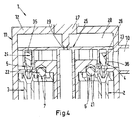
図3〜6を参照すると、図1及び2によるエジェクタ配置の拡大部が示されている。図3は、全てのエジェクタ2、3が閉鎖される場合、すなわち全ての弁体23、24が全てのエジェクタ2、3の輸送口4、5を閉鎖する場合の状態を示す。図3〜6は、エジェクタ3が閉鎖された状態を維持する一方で、どのようにエジェクタ2が共通アクチュエータ25によって開放されるかを示す。この実施形態によれば、これは、共通軸13と垂直なより大きい断面を有する部分31、32及び共通軸13と垂直なより小さい断面を有する部分33、34を含む弁体23、24によって達成される。ここで、部分31、32、33、34は、円筒形状を有し、部分31、32が部分33、34よりも大きい直径を有する。異なる断面及び/又は直径の部分間に環状肩部37、38が配置される。共通アクチュエータ25、特に駆動要素26は、内部で弁体23、24が共通軸13と平行に移動できる空間35を含む。この目的を達成するために、空間35は、共通軸13に沿ったチャネル形状を有す。共通アクチュエータ25及び特に駆動要素26は、弁体23、24が空間35から出ることを防止するために、空間35の一端に弁体23、24のための止め部を更に含む。
3-6, there is shown an enlarged portion of the ejector arrangement according to FIGS. 1 and 2. FIG. 3 shows a state in which all the
図3において、共通アクチュエータ25の弁部材27は、パイロット孔29を閉鎖する。しかし、図4において、弁部材27は、共通軸13に沿って上方に短い距離だけ移動され、それによりパイロット孔29を開放する。従って、吸引ライン18とパイロットチャンバ28との間の流体接触が開放される。それにより、駆動要素26の上側と底部側との間の圧力差は、結果として駆動要素26への合力を生じる。この力は、共通軸13に沿った駆動要素26の上方移動の原因となる。
In FIG. 3, the
図5で見て取れるように、弁体23に対応する止め部36は、環状肩部37において異なる断面の部分31、33間で弁体23と係合し、それにより弁体23を持ち上げ、輸送口4を開口する。従って、輸送流体は、エジェクタ2に入ることができ、吸引口6のエジェクタ側にかかる圧力を低減する。逆止弁21は、吸引チャンバ20と吸引口6のエジェクタ側との間の圧力差から生じる力によって開放される。吸引ライン18からの流体は、従って、エジェクタ2に入り、輸送ライン10から到来する輸送流体と混合する。出口8においてエジェクタ2を出る流体は、吸引ライン18における流体と比較して上昇した圧力を有する。
As can be seen in FIG. 5, the
図3〜6で見て取れるように、第2のエジェクタ3は作動しておらず、すなわち、輸送口5は弁体24によって閉鎖された状態を維持する。これは、弁体23の部分33と比較して長い弁体24の部分34によって達成される。エジェクタ2の止め部36は、従って、エジェクタ3の止め部36が弁体24の肩部38と係合するよりも早く、弁体23の肩部37と係合する。しかし、弁部材27が図6の状態と比較して共通軸13に沿って更に上方に移動される場合、駆動部材26は、圧力差によって更に上方に押し上げられ、それにより弁体24も上方に持ち上げ、輸送口5を開口する。この実施形態において見て取れるように、第2のエジェクタ3の弁体24は、エジェクタ2の弁体23の開放操作中、閉鎖位置に留まっている。換言すれば、第2のエジェクタ3は、第1のエジェクタ2が共通アクチュエータ25によって完全に開放された後にのみ開放される。従って、個々の弁体23、24の相対的な長さを選択することにより、個々の弁体23、24が駆動要素26によって上方に持ち上げられる共通軸13に沿った駆動要素26の位置を定義することができる。各エジェクタ2、3は、従って、所定の順序で開放することができる。これは、エジェクタ配置を通る質量流量の良好な比例制御を可能にする。
As can be seen in FIGS. 3 to 6, the
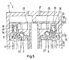
図7は、本発明によるエジェクタ配置40の第2の実施形態を示す。対応する参照符号は同じ数字によって示される。エジェクタ配置40の開放状態は、図3と同じ状態に対応し、すなわち、両方は、エジェクタ41、42が完全に閉鎖されることを明示的に示す。第1の実施形態とは対照的に、弁体43、44は、ここで全く同じものである。換言すれば、より大きい断面を有する部分45、46は、両方の弁体43、44に対して同じ長さを有し、より小さい断面を有する部分47、48は、両方の弁体43、44に対して同じ長さを有する。
FIG. 7 shows a second embodiment of the
この実施形態における個々のエジェクタ41、44間の開放動作における差は、各エジェクタ41、42に対して異なる長さを有する空間49、50を有することによって達成される。同時に、エジェクタ41の止め部51は、共通アクチュエータ55が開放方向、すなわちこの場合には上方に移動される場合、止め部53が弁体44の肩部54と係合するよりも早く、弁体43の肩部52と係合する。第1の実施形態と比較した第2の実施形態の利点は、全ての弁体43、44が同じであり、従って、弁体を誤った空間に挿入することによる誤った組み立ての危険がないため、エジェクタ配置の組み立てが簡素化されることである。第2の実施形態における共通アクチュエータ55は、従って、各空間49、50に対して異なる長さを有する、空間49、50との非対称の駆動要素56を含む。図1〜6における第1の実施形態によれば、駆動要素26の空間35は、全て共通軸13に沿って同じ長さを有する。
The difference in the opening action between the
Claims (15)
Applications Claiming Priority (3)
| Application Number | Priority Date | Filing Date | Title |
|---|---|---|---|
| EP15173582.6 | 2015-06-24 | ||
| EP15173582.6A EP3109568B1 (en) | 2015-06-24 | 2015-06-24 | Ejector arrangement |
| PCT/EP2016/061739 WO2016206903A1 (en) | 2015-06-24 | 2016-05-25 | Ejector arrangement |
Publications (3)
| Publication Number | Publication Date |
|---|---|
| JP2018522192A JP2018522192A (en) | 2018-08-09 |
| JP2018522192A5 JP2018522192A5 (en) | 2019-02-21 |
| JP6691556B2 true JP6691556B2 (en) | 2020-04-28 |
Family
ID=53487269
Family Applications (1)
| Application Number | Title | Priority Date | Filing Date |
|---|---|---|---|
| JP2017566088A Expired - Fee Related JP6691556B2 (en) | 2015-06-24 | 2016-05-25 | Ejector arrangement |
Country Status (10)
| Country | Link |
|---|---|
| US (1) | US10816015B2 (en) |
| EP (1) | EP3109568B1 (en) |
| JP (1) | JP6691556B2 (en) |
| CN (1) | CN107787435B (en) |
| BR (1) | BR112017027685A2 (en) |
| CA (1) | CA2987994A1 (en) |
| ES (1) | ES2656674T3 (en) |
| MX (1) | MX2017016615A (en) |
| RU (1) | RU2671663C1 (en) |
| WO (1) | WO2016206903A1 (en) |
Families Citing this family (1)
| Publication number | Priority date | Publication date | Assignee | Title |
|---|---|---|---|---|
| KR102602247B1 (en) * | 2021-04-29 | 2023-11-14 | 이에스엠티 주식회사 | Disinfector |
Family Cites Families (34)
| Publication number | Priority date | Publication date | Assignee | Title |
|---|---|---|---|---|
| US2126384A (en) * | 1936-01-08 | 1938-08-09 | Honeywell Regulator Co | Multiple steam jet refrigerating system |
| US2106362A (en) * | 1936-04-24 | 1938-01-25 | Westinghouse Electric & Mfg Co | Steam jet refrigeration apparatus |
| US3220210A (en) * | 1961-09-05 | 1965-11-30 | Carrier Corp | Jet refrigeration apparatus |
| US3255708A (en) * | 1964-01-02 | 1966-06-14 | Boeing Co | Ejector pump |
| US3380649A (en) * | 1965-10-19 | 1968-04-30 | Gen Electric | Reactor pumping system |
| DE69221935T2 (en) * | 1991-05-22 | 1998-04-09 | Toshiba Kawasaki Kk | Steam injector system |
| US5799831A (en) * | 1996-03-20 | 1998-09-01 | Ecolab Inc. | Dual aspirator |
| RU2133884C1 (en) * | 1998-03-27 | 1999-07-27 | Попов Сергей Анатольевич | Liquid-and-gas ejector (versions) |
| DE19817249C1 (en) * | 1998-04-18 | 1999-08-26 | Schmalz J Gmbh | Ejector for vacuum production, particularly for vacuum handling apparatus |
| RU2142075C1 (en) * | 1998-04-20 | 1999-11-27 | Попов Сергей Анатольевич | Pump-ejector plant (versions) |
| IL125791A (en) * | 1998-08-13 | 2004-05-12 | Dan Greenberg | Vacuum pump |
| RU2184880C1 (en) * | 2000-12-18 | 2002-07-10 | Владимир Гдальевич Мирский | Pump-ejector plant for compression of gaseous medium |
| US7776213B2 (en) * | 2001-06-12 | 2010-08-17 | Hydrotreat, Inc. | Apparatus for enhancing venturi suction in eductor mixers |
| JP3941602B2 (en) | 2002-02-07 | 2007-07-04 | 株式会社デンソー | Ejector type decompression device |
| JP3951885B2 (en) * | 2002-10-22 | 2007-08-01 | 日産自動車株式会社 | Fuel cell system |
| DE10250532B3 (en) * | 2002-10-29 | 2004-07-01 | J. Schmalz Gmbh | Propellant powered ejector assembly |
| JP2004198002A (en) | 2002-12-17 | 2004-07-15 | Denso Corp | Vapor compression type refrigerator |
| US7309537B2 (en) * | 2003-09-18 | 2007-12-18 | Ballard Power Systems Inc. | Fuel cell system with fluid stream recirculation |
| DE102004047782A1 (en) * | 2004-06-18 | 2006-01-05 | Robert Bosch Gmbh | Device for conveying fuel |
| JP4259531B2 (en) | 2005-04-05 | 2009-04-30 | 株式会社デンソー | Ejector type refrigeration cycle unit |
| JP2006342765A (en) * | 2005-06-10 | 2006-12-21 | Smc Corp | Vacuum unit and method for manufacturing filter used for vacuum unit |
| US20070020114A1 (en) * | 2005-07-01 | 2007-01-25 | Mcfarland Noel W | Jet pump |
| RU2317451C1 (en) * | 2006-06-13 | 2008-02-20 | Государственное образовательное учреждение высшего профессионального образования "Санкт-Петербургский государственный морской технический университет" | Jet pump starting system |
| SE531940C2 (en) * | 2007-01-10 | 2009-09-15 | Xerex Ab | Ejector |
| SE530787C2 (en) * | 2007-01-16 | 2008-09-09 | Xerex Ab | Ejector device with ventilation function |
| JP4678604B2 (en) * | 2007-08-01 | 2011-04-27 | Smc株式会社 | Vacuum generation unit |
| JP5062066B2 (en) | 2008-07-04 | 2012-10-31 | 株式会社デンソー | Ejector type refrigeration cycle evaporator unit |
| DE102009047085A1 (en) * | 2009-11-24 | 2011-06-01 | J. Schmalz Gmbh | Compressed air operated vacuum generator |
| EP2646763B1 (en) * | 2010-11-30 | 2016-08-10 | Carrier Corporation | Ejector |
| CN103270379B (en) * | 2011-01-04 | 2016-03-16 | 开利公司 | Injector |
| DE102011017739A1 (en) * | 2011-04-28 | 2012-10-31 | Uwe Würdig | Method and device for enriching a liquid with gas |
| US9074523B2 (en) * | 2012-11-16 | 2015-07-07 | Ford Global Technologies, Llc | Vacuum-actuated wastegate |
| DE102016111910A1 (en) * | 2016-06-29 | 2018-01-04 | Eppendorf Ag | Dosing head, dosing device comprising a dosing head and method for dosing by means of a dosing head |
| US10495039B2 (en) * | 2017-03-30 | 2019-12-03 | Delphi Technologies Ip Limited | Fuel system having a jet pump |
-
2015
- 2015-06-24 EP EP15173582.6A patent/EP3109568B1/en active Active
- 2015-06-24 ES ES15173582.6T patent/ES2656674T3/en active Active
-
2016
- 2016-05-25 CN CN201680037053.8A patent/CN107787435B/en active Active
- 2016-05-25 CA CA2987994A patent/CA2987994A1/en not_active Abandoned
- 2016-05-25 BR BR112017027685A patent/BR112017027685A2/en not_active IP Right Cessation
- 2016-05-25 MX MX2017016615A patent/MX2017016615A/en active IP Right Grant
- 2016-05-25 RU RU2018101144A patent/RU2671663C1/en active
- 2016-05-25 WO PCT/EP2016/061739 patent/WO2016206903A1/en active Application Filing
- 2016-05-25 JP JP2017566088A patent/JP6691556B2/en not_active Expired - Fee Related
- 2016-05-25 US US15/738,841 patent/US10816015B2/en active Active
Also Published As
| Publication number | Publication date |
|---|---|
| EP3109568A1 (en) | 2016-12-28 |
| US20180180064A1 (en) | 2018-06-28 |
| US10816015B2 (en) | 2020-10-27 |
| CN107787435B (en) | 2019-11-05 |
| WO2016206903A1 (en) | 2016-12-29 |
| BR112017027685A2 (en) | 2018-09-04 |
| EP3109568B1 (en) | 2017-11-01 |
| RU2671663C1 (en) | 2018-11-06 |
| JP2018522192A (en) | 2018-08-09 |
| MX2017016615A (en) | 2018-05-15 |
| ES2656674T3 (en) | 2018-02-28 |
| CN107787435A (en) | 2018-03-09 |
| CA2987994A1 (en) | 2016-12-29 |
Similar Documents
| Publication | Publication Date | Title |
|---|---|---|
| US20170184219A1 (en) | Valve cage for receiving a valve member and method for operating a control valve with a valve cage and a valve member | |
| US8245728B2 (en) | Quantum fluid transfer system | |
| US8375974B2 (en) | Temperature controlling device | |
| US8985548B2 (en) | Composite valve | |
| CN107654435B (en) | A kind of proportional flow shut-off valve | |
| JP6691556B2 (en) | Ejector arrangement | |
| EP2818779B1 (en) | Solenoid valve | |
| US9476514B2 (en) | Valve, in particular a pressure regulating valve or pressure limiting valve | |
| CN102803745A (en) | Proportional valve assembly | |
| KR20140022457A (en) | Valve assembly | |
| CN108843642B (en) | Electromagnetic valve for movable arm oil cylinder of excavator | |
| US10816099B2 (en) | Spool valve | |
| MX2012012124A (en) | Device and method of enchancing production of hydrocarbons. | |
| EP3115592B1 (en) | A control valve for fuel injector and a fuel injector | |
| CN108050121B (en) | Hydraulic control system of plug-in type control valve and winch brake | |
| EP1212562B1 (en) | Electromagnetically actuated valve, especially for hydraulic braking systems of motor vehicles | |
| KR20120085926A (en) | Control valve, in particular for metering in a fluid for a delivery pump which is arranged downstream | |
| US8333178B2 (en) | Control valve arrangement | |
| US9097362B2 (en) | Fast switching hydraulic pilot valve with hydraulic feedback | |
| TW201920857A (en) | Valve device | |
| US20160146368A1 (en) | Solenoid valve with progressive spring inside anchor | |
| KR101805798B1 (en) | Pressure Control Device And Fluid Velocity In The Valve | |
| CA2930816A1 (en) | Water discharge valve for toilets | |
| JPWO2021055389A5 (en) | ||
| JP2001193703A (en) | Hydraulic control device |
Legal Events
| Date | Code | Title | Description |
|---|---|---|---|
| A521 | Request for written amendment filed |
Free format text: JAPANESE INTERMEDIATE CODE: A523 Effective date: 20190109 |
|
| A621 | Written request for application examination |
Free format text: JAPANESE INTERMEDIATE CODE: A621 Effective date: 20190109 |
|
| A977 | Report on retrieval |
Free format text: JAPANESE INTERMEDIATE CODE: A971007 Effective date: 20191122 |
|
| A131 | Notification of reasons for refusal |
Free format text: JAPANESE INTERMEDIATE CODE: A131 Effective date: 20191217 |
|
| A521 | Request for written amendment filed |
Free format text: JAPANESE INTERMEDIATE CODE: A523 Effective date: 20200317 |
|
| TRDD | Decision of grant or rejection written | ||
| A01 | Written decision to grant a patent or to grant a registration (utility model) |
Free format text: JAPANESE INTERMEDIATE CODE: A01 Effective date: 20200407 |
|
| A61 | First payment of annual fees (during grant procedure) |
Free format text: JAPANESE INTERMEDIATE CODE: A61 Effective date: 20200410 |
|
| R150 | Certificate of patent or registration of utility model |
Ref document number: 6691556 Country of ref document: JP Free format text: JAPANESE INTERMEDIATE CODE: R150 |
|
| LAPS | Cancellation because of no payment of annual fees |