JP6691069B2 - Subscriber line terminal device and band allocation method - Google Patents
Subscriber line terminal device and band allocation method Download PDFInfo
- Publication number
- JP6691069B2 JP6691069B2 JP2017055062A JP2017055062A JP6691069B2 JP 6691069 B2 JP6691069 B2 JP 6691069B2 JP 2017055062 A JP2017055062 A JP 2017055062A JP 2017055062 A JP2017055062 A JP 2017055062A JP 6691069 B2 JP6691069 B2 JP 6691069B2
- Authority
- JP
- Japan
- Prior art keywords
- setting value
- setting
- band
- hardware
- value
- Prior art date
- Legal status (The legal status is an assumption and is not a legal conclusion. Google has not performed a legal analysis and makes no representation as to the accuracy of the status listed.)
- Active
Links
Images

Landscapes
- Small-Scale Networks (AREA)
Description
本発明は、加入者線端局装置及び帯域割当方法に関する。 The present invention relates to a subscriber line terminal device and a band allocation method.
アクセスサービスの高速化に対するニーズの高まりに応じて、FTTH(Fiber To The Home)が世界的に普及している。FTTHのサービスの大部分では、加入者線端局装置(OLT: Optical Line Terminal)が、時分割多重(TDM: Time Division Multiplexing)によって複数の加入者線終端装置(ONU: Optical Network Unit)を収容している。FTTHのサービスは、経済性に優れた方式であるPON(Passive Optical Network)方式によって提供される場合がある。 FTTH (Fiber To The Home) has become widespread worldwide in response to the growing need for faster access services. In most of FTTH services, a subscriber line terminal equipment (OLT: Optical Line Terminal) accommodates a plurality of subscriber line terminating devices (ONU: Optical Network Unit) by time division multiplexing (TDM). is doing. The FTTH service may be provided by a PON (Passive Optical Network) method, which is an economical method.
TDM−PONの上り通信では、各ONUは、OLTによって割り当てられたシステム帯域を共有している。各ONUは、OLTから自装置に通知された送信許可時間に光信号をOLTに送信することによって、光信号同士の衝突を防いでいる。 In the upstream communication of the TDM-PON, each ONU shares the system band allocated by the OLT. Each ONU prevents the optical signals from colliding with each other by transmitting the optical signal to the OLT during the transmission permission time notified from the OLT to the own device.
現在の主力のPONシステムは、伝送速度がギガビット級であるGE−PON(Gigabit Ethernet(登録商標) PON)である(非特許文献1参照)。映像配信サービスの進展に加え、大容量ファイルをアップロード及びダウンロードするアプリケーションの登場などによって、PONシステムには更なる大容量化が求められている。 The current main PON system is GE-PON (Gigabit Ethernet (registered trademark) PON) whose transmission speed is gigabit (see Non-Patent Document 1). With the advent of applications for uploading and downloading large-capacity files in addition to the development of video distribution services, the PON system is required to have a larger capacity.
PONシステムは、OLTと、OLTと光ファイバを経由して接続される複数のONUとによって構成される。ONUは、PC(Personal Computer)やルータ等の端末装置と接続される。OLTは端末装置からの要求に対してユーザへサービス提供するためのサーバや通信装置等の上位ネットワーク装置と接続される。 The PON system is composed of an OLT and a plurality of ONUs connected to the OLT via optical fibers. The ONU is connected to a terminal device such as a PC (Personal Computer) or a router. The OLT is connected to a host network device such as a server or a communication device for providing a service to a user in response to a request from a terminal device.
OLTは、ONUからの接続要求に対し、ONU毎に異なるLLID(Logic Link ID)を付与する。PON区間において、ONUはLLIDを用いてユーザー識別を行う。また、上位装置は、IEEE802.1等で標準化されたVID(VLAN−ID)を用いてユーザ識別を行う。 The OLT gives a LLID (Logic Link ID) different for each ONU to a connection request from the ONU. In the PON section, the ONU identifies the user using the LLID. Further, the higher-level device identifies the user by using a VID (VLAN-ID) standardized by IEEE 802.1 or the like.
OLTは、LLID又はVIDを用いてユーザを識別する。ONUはOLTから端末装置に向けての通信時は、VIDを削除し端末装置へデータを送信する。ONUは、端末装置からOLTに向けての通信時はVIDを付与してデータを送信する。 The OLT identifies the user using the LLID or VID. The ONU deletes the VID and transmits data to the terminal device during communication from the OLT to the terminal device. The ONU assigns a VID and transmits data during communication from the terminal device to the OLT.
2R3C(2rate3color)は標準化技術(RFC4155)であり、優先制御機能に関する機能である。2R3Cは、ユーザへの最小補償帯域と、最大補償帯域を有することで通信を制御する機能である。 2R3C (2rate3color) is a standardized technology (RFC4155) and is a function related to a priority control function. The 2R3C is a function of controlling communication by having a minimum compensation band for the user and a maximum compensation band.
2R3Cは、CIR(Committed Information Rate)と、EIR(Excess Information Rate)との2つの基準となる通信速度を有する。CIR以下の帯域は、最低補償帯域である。EIR以下の帯域は、帯域に余裕がある場合に使用されても良い帯域である。これを利用して、2R3Cを帯域制御する。 The 2R3C has two reference communication speeds of CIR (Committed Information Rate) and EIR (Excess Information Rate). The band below the CIR is the minimum compensation band. The band below the EIR is a band that may be used when there is a margin in the band. Utilizing this, band control of 2R3C is performed.
帯域制御を行う際、OLTに対して、CLI(Command Line Interface)によってオペレータがコマンドを発行して、OLT内のチップに対して設定を行う。しかし、集線スイッチやハードウェアチップでは、細かい精度の設定ができず、離散的な値を設定することになる。そのため、オペレータによる設定値は、ハードウェアチップの設定値に近い値か、切り上げた値かのいずれかひとつの値に変換されてOLT内の制御部に設定される。その結果、顧客に割り当てるべき帯域(以下「契約帯域」という。)を確保できない場合があった(特許文献1参照)。 When performing band control, the operator issues a command to the OLT by CLI (Command Line Interface) to set the chip in the OLT. However, the concentrator switch and the hardware chip cannot set fine precision, and thus set discrete values. Therefore, the setting value set by the operator is converted into one of a value close to the setting value of the hardware chip and a value rounded up, and set in the control unit in the OLT. As a result, there is a case where a band to be assigned to a customer (hereinafter referred to as “contract band”) cannot be secured (see Patent Document 1).
上記事情に鑑み、本発明は、ユーザへの契約帯域を確保する帯域制御を可能とする加入者線端局装置及び帯域割当方法を提供することを目的としている。 In view of the above circumstances, it is an object of the present invention to provide a subscriber line terminal station device and a band allocation method that enable band control to secure a contract band for a user.
本発明の一態様は、帯域制御に関する設定値を入力する設定値入力部と、前記設定値入力部から受信した前記設定値に基づいて帯域制御のハードウェアチップへの設定可能な値のうち所定の条件で決定されるハードウェア設定値を決定した上で、前記帯域制御のハードウェアチップへ設定値を設定する帯域制御値設定部と、データのやり取りのためのタグであってVID(VLAN−ID)及び内部タグを有する識別タグをフレームに付与する内部タグ付与部と、を有し、前記帯域制御値設定部は、前記ハードウェア設定値の決定において前記内部タグを除いたフレームのサイズに基づいて前記ハードウェア設定値を決定し、前記帯域制御値設定部は、最小補償帯域に関する設定値を前記ハードウェア設定値に設定する場合には、前記最小補償帯域に関する設定値を、受信した前記帯域制御に関する設定値以上で、かつ、前記設定可能な値のうち前記帯域制御に関する設定値に最も近い値とすることを前記所定の条件として最小補償帯域に関する設定値を前記ハードウェア設定値に設定する最小補償帯域設定部と、最大補償帯域に関する設定値を前記ハードウェア設定値に設定する場合には、前記最大補償帯域に関する設定値を受信した前記帯域制御に関する設定値以下で、かつ、前記設定可能な値のうち前記帯域制御に関する設定値に最も近い値を最大補償帯域に関する設定値とすることを前記所定の条件として最大補償帯域に関する設定値を前記ハードウェア設定値に設定する最大補償帯域設定部と、の少なくとも一方を有する加入者線端局装置である。 According to one aspect of the present invention, a set value input unit for inputting a set value related to band control, and a predetermined value among settable values for a band control hardware chip based on the set value received from the set value input unit. After determining the hardware setting value determined by the condition of (1), a band control value setting unit that sets the setting value to the bandwidth control hardware chip, and a tag for data exchange, which is a VID (VLAN- an identification tag having an ID) and internal tags possess an internal tag attaching portion to be applied to the frame, wherein the band control value setting unit, the size of the frame excluding the internal tag in the determination of the hardware settings The band control value setting unit determines the hardware setting value based on the above, and when the band control value setting unit sets the setting value related to the minimum compensation band to the hardware setting value, A setting for the minimum compensation band, with the predetermined condition being that the setting value for the band is equal to or greater than the received setting value for the band control and is the closest to the setting value for the band control among the settable values. A minimum compensation band setting unit that sets a value to the hardware setting value; and, when setting a setting value related to the maximum compensation band to the hardware setting value, relates to the band control that has received the setting value related to the maximum compensation band. The set value related to the maximum compensation band is set to the hardware under the predetermined condition that a value that is the set value or less and is closest to the set value related to the band control is set to the set value related to the maximum compensation band. the maximum compensation range setting unit for setting the set value, a line Termination to have at least one.
本発明の一態様は、上記の加入者線端局装置であって、前記加入者線端局装置には下位に加入者線終端装置が接続され、前記帯域制御値設定部が、前記設定値入力部から受信した帯域制御に関する設定値と、前記加入者線終端装置の下位の装置に転送する際に用いられる帯域に基づいて、前記帯域制御のハードウェアチップへの前記設定可能な値のうち前記所定の条件で決定される前記ハードウェア設定値を決定した上で、前記帯域制御のハードウェアチップへ前記ハードウェア設定値を設定する。 One aspect of the present invention is the subscriber line terminal station device described above, wherein a subscriber line terminal device is connected to the subscriber line terminal station device in a lower order, and the band control value setting unit sets the set value. Of the settable values for the bandwidth control hardware chip, based on the setting value relating to the bandwidth control received from the input unit and the bandwidth used when transferring to the lower device of the subscriber line termination device. After determining the hardware setting value determined under the predetermined condition, the hardware setting value is set in the bandwidth control hardware chip.
本発明の一態様は、帯域制御に関する設定値を入力する設定値入力方法と、前記設定値入力方法から受信した前記設定値に基づいて帯域制御のハードウェアチップへの設定可能な値のうち所定の条件で決定されるハードウェア設定値を決定した上で、前記帯域制御のハードウェアチップへ設定値を設定する帯域制御値設定方法と、データのやり取りのためのタグであってVID(VLAN−ID)及び内部タグを有する識別タグをフレームに付与する内部タグ付与方法と、を有し、前記帯域制御値設定方法では、前記ハードウェア設定値の決定において前記内部タグを除いたフレームのサイズに基づいて前記ハードウェア設定値が決定され、前記帯域制御値設定方法は、最小補償帯域に関する設定値を前記ハードウェア設定値に設定する場合には、前記最小補償帯域に関する設定値を、受信した前記帯域制御に関する設定値以上で、かつ、前記設定可能な値のうち前記帯域制御に関する設定値に最も近い値とすることを前記所定の条件として最小補償帯域に関する設定値を前記ハードウェア設定値に設定する最小補償帯域設定方法と、最大補償帯域に関する設定値を前記ハードウェア設定値に設定する場合には、前記最大補償帯域に関する設定値を受信した前記帯域制御に関する設定値以下で、かつ、前記設定可能な値のうち前記帯域制御に関する設定値に最も近い値を最大補償帯域に関する設定値とすることを前記所定の条件として最大補償帯域に関する設定値を前記ハードウェア設定値に設定する最大補償帯域設定方法と、の少なくとも一方を有する帯域割当方法である。 According to one aspect of the present invention, a set value input method for inputting a set value relating to band control, and a predetermined value among settable values for a band control hardware chip based on the set value received from the set value input method. A band control value setting method of setting the set value to the hardware chip for band control after determining the hardware set value determined by the condition, and a tag for transmitting and receiving data, which is VID (VLAN- an identification tag having an ID) and internal tags possess an internal tagging method to be applied to the frame, and in the bandwidth control value setting method, the size of the frame excluding the internal tag in the determination of the hardware settings In the case where the hardware setting value is determined based on the above, and the band control value setting method sets the setting value related to the minimum compensation band to the hardware setting value. The predetermined condition is that the set value related to the minimum compensation band is equal to or larger than the received set value related to the band control and is the closest value to the set value related to the band control among the settable values. A minimum compensation band setting method for setting a setting value related to the minimum compensation band to the hardware setting value, and a setting value related to the maximum compensation band when the setting value related to the maximum compensation band is set to the hardware setting value. The setting related to the maximum compensation band is set to be the setting value related to the maximum compensation band that is equal to or less than the set value related to the band control and that is the closest to the setting value related to the band control among the settable values. the maximum compensation range setting method for setting a value in the hardware settings, a band allocation method for have at least one.
本発明により、ユーザへの契約帯域を確保する帯域制御が可能である。 According to the present invention, it is possible to perform bandwidth control that secures a contract bandwidth for users.
(第1実施形態)
以下、図面を参照して、本発明の実施の形態について説明する。図1は、第1の実施形態における光通信システム1の構成の例を示す図である。光通信システム1は、光信号を用いて通信するGE−PONシステムである。第1実施形態の光通信システム1は、端局装置10と、終端装置20−1〜20−N(Nは2以上の整数)と、光分配器30とを備える。
(First embodiment)
Hereinafter, embodiments of the present invention will be described with reference to the drawings. FIG. 1 is a diagram illustrating an example of the configuration of the optical communication system 1 according to the first embodiment. The optical communication system 1 is a GE-PON system that communicates using optical signals. The optical communication system 1 of the first embodiment includes a
端局装置10は、OLTである。端局装置10は、終端装置20による接続要求信号を取得した場合に、接続要求信号に応答するための信号である応答信号を前述の終端装置20に送信し、前述の終端装置20と通信を行う。なお、端局装置10の各機能の全て又は一部は、ASIC(Application Specific Integrated Circuit)やPLD(Programmable Logic Device)やFPGA(Field Programmable Gate Array)等のハードウェアを用いて実現されてもよい。
The
端局装置10は、光ファイバを通じて、終端装置20と通信を行う。端局装置10は、終端装置20との通信におけるユーザ識別の方法として、LLIDを用いる。また、端局装置10は、図示しないもののインターネット等の上位ネットワークに接続された装置(以下「上位局」という。)とも通信を行う。端局装置10は、上位局との通信においては、ユーザ識別の方法として、VIDを用いる。
The
終端装置20は、加入者線終端装置である。終端装置20は、自装置に割り当てられた識別子を表す情報を含む接続要求信号を端局装置10に送信することによって、自装置と端局装置10との間の接続を端局装置10に要求する。終端装置20は、接続要求信号に応答するための信号である応答信号を端局装置10から取得した場合、自装置と端局装置10との間でPONリンクが確立したと判定する。光通信システム1に接続された終端装置20は、自装置と端局装置10との間でPONリンクが確立しない場合、所定周期で接続要求信号を端局装置10に再送信する。終端装置20は、端局装置10のデータを取得した際に、フレームに付与されたVIDを削除する。
The
光分配器30は、例えば光カプラである。光分配器30は、端局装置10又は終端装置20の間に存在し、信号を搬送する光の結合と分配とを行う。
The
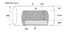
図2は、第1の実施形態の光通信システム1が有する機能である2R3Cのイメージ図である。2R3Cは、前述したようにユーザへの最小補償帯域CIRと、最大補償帯域EIRとを制御する機能である。2R3Cは、一般的に帯域ごとに色によって分類されて表現される。 FIG. 2 is an image diagram of 2R3C, which is a function of the optical communication system 1 of the first embodiment. The 2R3C is a function of controlling the minimum compensation band CIR and the maximum compensation band EIR to the user as described above. 2R3C is generally expressed by being classified by color for each band.
図2において、概念図91は、通信で扱う全帯域を表すイメージ図である。
図2において、GREENで表される帯域はCIRであり、概念図92で表される。概念図92は、各終端装置20に対して割り当てられる最低補償の帯域を表す。概念図92で表される帯域は、一般的に緑色で表示される。CIRは、例えば、5Mbit/sである。
図2において、YELLOWで表される帯域はEIRであり、概念図93で表される。概念図93で表される帯域は、一般的に黄色で表示される。EIRは、通信においてCIRの帯域を超える通信帯域を必要とする場合に、EIRの帯域に空きがあれば使用される帯域である。
図2において、REDで表される帯域は、正常なデータ通信ができない帯域を表す。例えば、端局装置10と複数の終端装置20の間の通信量が多くREDで表される帯域も使用せざるを得なくなる場合には、送られてきた情報は破棄される。REDで表される帯域は、一般的に赤色で表示される。
In FIG. 2, a conceptual diagram 91 is an image diagram showing the entire band handled in communication.
In FIG. 2, the band represented by GREEN is CIR and is represented by a conceptual diagram 92. The conceptual diagram 92 represents the band of the minimum compensation allocated to each terminating
In FIG. 2, the band represented by YELLOW is EIR and is represented by a conceptual diagram 93. The band represented by the conceptual diagram 93 is generally displayed in yellow. The EIR is a band used when there is a vacant EIR band when a communication band exceeding the CIR band is required for communication.
In FIG. 2, a band represented by RED represents a band in which normal data communication cannot be performed. For example, when there is a large amount of communication between the
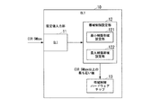
次に、端局装置10の機能構成の例を説明する。
図3は、端局装置10の機能構成例を示す図である。
端局装置10は、設定値入力部11と、帯域制御設定部12と、帯域制御ハードウェアチップ13とを備える。
Next, an example of the functional configuration of the
FIG. 3 is a diagram illustrating a functional configuration example of the
The
設定値入力部11は、CLI(Command Line Interface)である。設定値入力部11は、オペレーティングシステム装置(以下「オペレータ」という。)が指示する帯域制御ハードウェアチップ13に設定する設定値(以下「CLI設定値」という。)、を帯域制御設定部12に指示するコマンドを発行する。コマンドはCLI設定値を整数値で指示する。
The set
帯域制御設定部12は、最小補償帯域設定部121と、最大補償帯域設定部122とを備える。帯域制御設定部12は、帯域制御ハードウェアチップ13に設定する設定値(以下「HW設定値」という。)を決定する。帯域制御設定部12は、設定値入力部11にて発行されたコマンドに基づいて、HW設定値を決定する。帯域制御設定部12は、決定したHW設定値を帯域制御ハードウェアチップ13に設定する。HW設定値はハードウェア設定値である。
The band
最小補償帯域設定部121は、設定値入力部11が発行したコマンドに基づいて、HW設定値を決定する。コマンドが最小補正帯域に関する場合には、受信したコマンドの指示する設定値以上で、かつ最も近い値の設定可能なHW設定値を決定する。ここで、設定可能なHW設定値とは、ユーザへの契約帯域を順守可能とするHW設定値を意味する。
The minimum compensation
最大補償帯域設定部122は、設定値入力部11が発行したコマンドに基づいて、HW設定値を決定する。コマンドが最大補正帯域に関する場合には、受信したコマンドの指示する設定値以下で、かつ最も近い値の設定可能なHW設定値を決定する。ここで、設定可能なHW設定値とは、契約帯域を順守可能とするHW設定値を意味する。
The maximum compensation
帯域制御ハードウェアチップ13は、帯域制御のハードウェアチップである。帯域制御ハードウェアチップ13は、光通信システム1における帯域制御を行う。帯域制御ハードウェアチップ13のHW設定値は、帯域制御設定部12によって決定された値が設定される。帯域制御ハードウェアチップ13は、前述の設定可能な値の一覧のデータを記憶部(不図示)に保持してもよい。
The bandwidth
このように構成された端局装置10では、最小補償帯域設定部121が、HW設定値を、帯域制御ハードウェアチップ13が設定可能な設定値のうちCLI設置値以上で最も近い値とするために、契約帯域を順守した設定が可能となる。CIRをサービス上5Mとしたときに、オペレータがHW設定値を5Mに設定した通信を使用することができる。また、このように構成された端局装置10では、最大補償帯域設定部122が、HW設定値を、帯域制御ハードウェアチップ13が設定可能な設定値のうちCLI設置値以下で最も近い値とするために、オペレータの設定値を超えることなく、余剰帯域を使用可能な設定が可能となる。
In the
(第2実施形態)
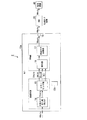
図4は、第2の実施形態における光通信システム2の構成の例を示す図である。
(Second embodiment)
FIG. 4 is a diagram showing an example of the configuration of the
光通信システム2は、端局装置10aと、終端装置20と、端末機器40とを備える。光通信システム2において、端局装置10aは終端装置20を介して、端末機器40と通信する。
The
端局装置10aは、帯域制御設定部12と、内部タグ付与部14と、カラーリング部15と、WRED部16と、内部タグ廃棄部17と、電気光変換部18とを備える。また、端局装置10aは、図示しないものの前述の設定値入力部11と、帯域制御ハードウェアチップ13とも備える。
The
帯域制御設定部12aは、第一の実施形態における帯域制御設定部12と同様の機能に加えて、さらに、VID及び内部タグを考慮し、内部タグがないものとして、HW設定値を計算する機能を有する。
The band
内部タグ付与部14は、端局装置10a内部におけるデータのやり取りを、識別タグを付与したフレームで行う。識別タグは、VID及び内部タグである。内部タグ付与部14は、上記VIDまたは内部タグをフレームに付与する。
The internal
カラーリング部15は、装置での通信レートを計算する。上記計算の結果、フレームが前述のGREENの帯域で通信されるのか、YELLOの帯域で通信されるのかが決定される。
The
内部タグ付与部14とカラーリング部15とを合わせて、集線SW部と表現してもよい。
The internal
WRED部16は、輻輳回避を行う。
The
内部タグ廃棄部17は、内部タグ付与部14において付与された内部タグを、フレームから削除する。
The internal
電気光変換部18は、電気信号を光信号に変換する。電気光変換部18で、信号が電気から光に変換されるために、端局装置10と終端装置20との通信は光によって行われる。
The electro-
終端装置20は、第一の実施形態における帯域制御設定部12と同様であり、端局装置10aのデータを取得した際に、VIDを削除する。
The terminating
端末機器40は、例えば自宅のパソコンなどの通信機器である。
The
図4は、第二の実施形態において、端局装置10内部におけるフレームサイズと端末機器40におけるフレームサイズの違いを説明する図である。
FIG. 4 is a diagram for explaining the difference between the frame size in the
契約帯域は終端装置の下位側の端末機器での帯域である。すなわち、図4においては、64byteのデータを通信に用いる帯域が契約帯域となる。しかし、端局装置10a内部においては、VIDタグ及び内部タグが付与されているために、端局装置10aは72byteのデータを扱うことになる。そのため、帯域制御設定部12aは、VID及び内部タグを考慮して、内部タグがないものとしてHW設定値を計算する。VID及び内部タグを考慮したHW設定値の計算によって、誤差の無い設定が端局装置10aになされる。
The contract bandwidth is the bandwidth of the terminal device on the lower side of the terminating device. That is, in FIG. 4, the band in which the 64-byte data is used for communication is the contract band. However, since the VID tag and the internal tag are attached inside the
このように構成された端局装置10aでは、帯域制御設定部12aが、VID及び内部タグを考慮して、内部タグがないものとしてHW設定値を計算するため、CLIからの設定を適切な値として繁栄させることができる。
In the
以上、この発明の実施形態について図面を参照して詳述してきたが、具体的な構成はこの実施形態に限られるものではなく、この発明の要旨を逸脱しない範囲の設計等も含まれる。したがって、本発明の範囲は、特許請求の範囲及びその均等範囲によってのみ規定されるものである。 Although the embodiment of the present invention has been described in detail above with reference to the drawings, the specific configuration is not limited to this embodiment, and includes a design and the like within a range not departing from the gist of the present invention. Therefore, the scope of the present invention is defined only by the claims and their equivalents.
1…第一の実施形態における光通信システム,2…第二の実施形態における光通信システム 10…端局装置, 20…終端装置, 30…光分配器, 11…設定値入力部, 12…帯域制御設定部, 13…帯域制御ハードウェアチップ, 121…最小補償帯域設定部, 122…最大補償帯域設定部
DESCRIPTION OF SYMBOLS 1 ... Optical communication system in 1st embodiment, 2 ... Optical communication system in
Claims (3)
前記設定値入力部から受信した前記設定値に基づいて帯域制御のハードウェアチップへの設定可能な値のうち所定の条件で決定されるハードウェア設定値を決定した上で、前記帯域制御のハードウェアチップへ設定値を設定する帯域制御値設定部と、
データのやり取りのためのタグであってVID(VLAN−ID)及び内部タグを有する識別タグをフレームに付与する内部タグ付与部と、
を有し、
前記帯域制御値設定部は、前記ハードウェア設定値の決定において前記内部タグを除いたフレームのサイズに基づいて前記ハードウェア設定値を決定し、
前記帯域制御値設定部は、
最小補償帯域に関する設定値を前記ハードウェア設定値に設定する場合には、前記最小補償帯域に関する設定値を、受信した前記帯域制御に関する設定値以上で、かつ、前記設定可能な値のうち前記帯域制御に関する設定値に最も近い値とすることを前記所定の条件として最小補償帯域に関する設定値を前記ハードウェア設定値に設定する最小補償帯域設定部と、
最大補償帯域に関する設定値を前記ハードウェア設定値に設定する場合には、前記最大補償帯域に関する設定値を受信した前記帯域制御に関する設定値以下で、かつ、前記設定可能な値のうち前記帯域制御に関する設定値に最も近い値を最大補償帯域に関する設定値とすることを前記所定の条件として最大補償帯域に関する設定値を前記ハードウェア設定値に設定する最大補償帯域設定部と、
の少なくとも一方を有する加入者線端局装置。 A setting value input section for inputting setting values related to band control,
Based on the setting value received from the setting value input unit, after determining a hardware setting value that is determined by a predetermined condition among values that can be set to the bandwidth control hardware chip, the bandwidth control hardware A bandwidth control value setting unit that sets the setting value to the wear chip,
An internal tag assigning unit for assigning an identification tag having a VID (VLAN-ID) and an internal tag to a frame, which is a tag for exchanging data
Have a,
The bandwidth control value setting unit determines the hardware setting value based on the size of the frame excluding the internal tag in the determination of the hardware setting value,
The band control value setting unit,
When setting the setting value related to the minimum compensation band to the hardware setting value, the setting value related to the minimum compensation band is equal to or more than the received setting value related to the band control, and the band among the settable values is set. A minimum compensation band setting unit that sets the setting value related to the minimum compensation band to the hardware setting value under the predetermined condition that the value is closest to the setting value related to control;
When setting the setting value related to the maximum compensation band to the hardware setting value, the setting value related to the maximum compensation band is less than or equal to the setting value related to the band control, and the band control of the settable values is performed. A maximum compensation band setting unit that sets the setting value related to the maximum compensation band to the hardware setting value under the predetermined condition that the value closest to the setting value related to
Line Termination to have at least one.
前記帯域制御値設定部が、前記設定値入力部から受信した帯域制御に関する設定値と、前記加入者線終端装置の下位の装置に転送する際に用いられる帯域に基づいて、前記帯域制御のハードウェアチップへの前記設定可能な値のうち前記所定の条件で決定される前記ハードウェア設定値を決定した上で、前記帯域制御のハードウェアチップへ前記ハードウェア設定値を設定する
請求項1に記載の加入者線端局装置。 A subscriber line terminating device is connected to the subscriber line terminal device at a lower level,
The bandwidth control value setting unit, based on the bandwidth control setting value received from the setting value input unit and the bandwidth used when transferring to a lower device of the subscriber line termination device, the bandwidth control hardware. The hardware setting value is set in the bandwidth control hardware chip after determining the hardware setting value determined by the predetermined condition among the settable values to the wear chip. Subscriber line terminal equipment described.
前記設定値入力方法から受信した前記設定値に基づいて帯域制御のハードウェアチップへの設定可能な値のうち所定の条件で決定されるハードウェア設定値を決定した上で、前記帯域制御のハードウェアチップへ設定値を設定する帯域制御値設定方法と、
データのやり取りのためのタグであってVID(VLAN−ID)及び内部タグを有する識別タグをフレームに付与する内部タグ付与方法と、
を有し、
前記帯域制御値設定方法では、前記ハードウェア設定値の決定において前記内部タグを除いたフレームのサイズに基づいて前記ハードウェア設定値が決定され、
前記帯域制御値設定方法は、
最小補償帯域に関する設定値を前記ハードウェア設定値に設定する場合には、前記最小補償帯域に関する設定値を、受信した前記帯域制御に関する設定値以上で、かつ、前記設定可能な値のうち前記帯域制御に関する設定値に最も近い値とすることを前記所定の条件として最小補償帯域に関する設定値を前記ハードウェア設定値に設定する最小補償帯域設定方法と、
最大補償帯域に関する設定値を前記ハードウェア設定値に設定する場合には、前記最大補償帯域に関する設定値を受信した前記帯域制御に関する設定値以下で、かつ、前記設定可能な値のうち前記帯域制御に関する設定値に最も近い値を最大補償帯域に関する設定値とすることを前記所定の条件として最大補償帯域に関する設定値を前記ハードウェア設定値に設定する最大補償帯域設定方法と、
の少なくとも一方を有する帯域割当方法。 Setting value input method to input the setting value related to bandwidth control,
Based on the setting value received from the setting value input method, after determining a hardware setting value that is determined under a predetermined condition among values that can be set to the bandwidth control hardware chip, the bandwidth control hardware Band control value setting method to set the setting value to wear chip,
An internal tag assigning method for assigning an identification tag, which is a tag for exchanging data and has a VID (VLAN-ID) and an internal tag, to a frame;
Have a,
In the bandwidth control value setting method, the hardware setting value is determined based on the size of the frame excluding the internal tag in the determination of the hardware setting value,
The band control value setting method,
When setting the setting value related to the minimum compensation band to the hardware setting value, the setting value related to the minimum compensation band is equal to or more than the received setting value related to the band control, and the band among the settable values is set. A minimum compensation band setting method for setting the setting value related to the minimum compensation band to the hardware setting value under the predetermined condition that the value is closest to the setting value related to control,
When setting the setting value related to the maximum compensation band to the hardware setting value, the setting value related to the maximum compensation band is less than or equal to the setting value related to the band control, and the band control of the settable values is performed. A maximum compensation band setting method for setting the setting value relating to the maximum compensation band to the hardware setting value under the predetermined condition that the value closest to the setting value relating to
Bandwidth allocation method for have at least one.
Priority Applications (1)
| Application Number | Priority Date | Filing Date | Title |
|---|---|---|---|
| JP2017055062A JP6691069B2 (en) | 2017-03-21 | 2017-03-21 | Subscriber line terminal device and band allocation method |
Applications Claiming Priority (1)
| Application Number | Priority Date | Filing Date | Title |
|---|---|---|---|
| JP2017055062A JP6691069B2 (en) | 2017-03-21 | 2017-03-21 | Subscriber line terminal device and band allocation method |
Publications (2)
| Publication Number | Publication Date |
|---|---|
| JP2018157527A JP2018157527A (en) | 2018-10-04 |
| JP6691069B2 true JP6691069B2 (en) | 2020-04-28 |
Family
ID=63716881
Family Applications (1)
| Application Number | Title | Priority Date | Filing Date |
|---|---|---|---|
| JP2017055062A Active JP6691069B2 (en) | 2017-03-21 | 2017-03-21 | Subscriber line terminal device and band allocation method |
Country Status (1)
| Country | Link |
|---|---|
| JP (1) | JP6691069B2 (en) |
Family Cites Families (7)
| Publication number | Priority date | Publication date | Assignee | Title |
|---|---|---|---|---|
| JP4283792B2 (en) * | 2005-08-29 | 2009-06-24 | 富士通株式会社 | Band control method and transmission apparatus |
| JP4955024B2 (en) * | 2009-02-12 | 2012-06-20 | 日本電信電話株式会社 | Reference clock frequency adjusting method and relay device |
| JP5320257B2 (en) * | 2009-10-28 | 2013-10-23 | 株式会社日立製作所 | Passive optical network system and optical subscriber terminal equipment |
| JP5669613B2 (en) * | 2011-02-18 | 2015-02-12 | 沖電気工業株式会社 | Dynamic bandwidth allocation method, optical communication network, and station side apparatus |
| JP2014033251A (en) * | 2012-08-01 | 2014-02-20 | Hitachi Ltd | Communication system and packet transmission method |
| WO2015063956A1 (en) * | 2013-11-01 | 2015-05-07 | 三菱電機株式会社 | Slave station device, master station device, control device, communication system and wavelength switching method |
| JP5867551B2 (en) * | 2014-06-18 | 2016-02-24 | 沖電気工業株式会社 | Optical phase-locked loop circuit |
-
2017
- 2017-03-21 JP JP2017055062A patent/JP6691069B2/en active Active
Also Published As
| Publication number | Publication date |
|---|---|
| JP2018157527A (en) | 2018-10-04 |
Similar Documents
| Publication | Publication Date | Title |
|---|---|---|
| US8989590B2 (en) | Pluggable OLT in Ethernet passive optical networks | |
| KR100480366B1 (en) | A system for VLAN configuration of E-PON and method thereof, its program stored recording medium | |
| KR100812833B1 (en) | Architecture, method and system of multiple high-speed servers to network in wdm based photonic burst-switched networks | |
| CN102739436B (en) | Unified network management system and method of hybrid fiber coaxial (hfc) network | |
| EP1838129A2 (en) | Method for configuring native VLAN and processing ethernet messages for a GPON system | |
| CN102100038B (en) | Gather status information from partner admin domains | |
| CN109075887B (en) | Channel Bonding in Multiwavelength Passive Optical Networks (PON) | |
| WO2008036494A2 (en) | Optical aggregation and proxy device | |
| US9413466B2 (en) | Distributed pon transceiver architecture | |
| CN103765917A (en) | A method of providing end-to-end connection in a unified optical and coaxial network | |
| JP6394695B2 (en) | Station side device, communication control method, and communication control program | |
| CN101897155A (en) | Office-side hub device, access control device and computer program thereof | |
| CN101536537B (en) | Method of managing connections in an optical access network and related platforms, exchanges, networks and computer software products | |
| US9866493B2 (en) | Dynamic activation of pre-deployed network resources | |
| JP5806408B2 (en) | Access node for communication network | |
| Pakpahan et al. | Peer-to-peer federated learning on software-defined optical access network | |
| JP6015323B2 (en) | Communication system, communication method, relay device, and master station device | |
| CN103973597B (en) | The management method and system of resource in a kind of Opto-electronic system | |
| JP6691069B2 (en) | Subscriber line terminal device and band allocation method | |
| JP5813539B2 (en) | Station side device and PON system | |
| WO2017028623A1 (en) | Method and device for channel configuration | |
| EP2388955B1 (en) | Method and apparatuses for performing network functions in a passive optical network | |
| Gumaste et al. | DynaSPOT: dynamic services provisioned optical transport test-bed—achieving multirate multiservice dynamic provisioning using strongly connected light-trail (SLiT) technology | |
| Hatano et al. | Standardization and technology trends in optical, wireless and virtualized access systems | |
| US11984930B2 (en) | Communication apparatus and communication method |
Legal Events
| Date | Code | Title | Description |
|---|---|---|---|
| A621 | Written request for application examination |
Free format text: JAPANESE INTERMEDIATE CODE: A621 Effective date: 20190305 |
|
| A977 | Report on retrieval |
Free format text: JAPANESE INTERMEDIATE CODE: A971007 Effective date: 20191210 |
|
| A131 | Notification of reasons for refusal |
Free format text: JAPANESE INTERMEDIATE CODE: A131 Effective date: 20191217 |
|
| A521 | Request for written amendment filed |
Free format text: JAPANESE INTERMEDIATE CODE: A523 Effective date: 20200207 |
|
| TRDD | Decision of grant or rejection written | ||
| A01 | Written decision to grant a patent or to grant a registration (utility model) |
Free format text: JAPANESE INTERMEDIATE CODE: A01 Effective date: 20200407 |
|
| A61 | First payment of annual fees (during grant procedure) |
Free format text: JAPANESE INTERMEDIATE CODE: A61 Effective date: 20200409 |
|
| R150 | Certificate of patent or registration of utility model |
Ref document number: 6691069 Country of ref document: JP Free format text: JAPANESE INTERMEDIATE CODE: R150 |
|
| S533 | Written request for registration of change of name |
Free format text: JAPANESE INTERMEDIATE CODE: R313533 |
|
| R350 | Written notification of registration of transfer |
Free format text: JAPANESE INTERMEDIATE CODE: R350 |