JP6688728B2 - Multilayer stack with overlapping harmonics for wide visible / infrared coverage - Google Patents
Multilayer stack with overlapping harmonics for wide visible / infrared coverage Download PDFInfo
- Publication number
- JP6688728B2 JP6688728B2 JP2016509011A JP2016509011A JP6688728B2 JP 6688728 B2 JP6688728 B2 JP 6688728B2 JP 2016509011 A JP2016509011 A JP 2016509011A JP 2016509011 A JP2016509011 A JP 2016509011A JP 6688728 B2 JP6688728 B2 JP 6688728B2
- Authority
- JP
- Japan
- Prior art keywords
- band
- reflection
- stack
- reflection band
- order
- Prior art date
- Legal status (The legal status is an assumption and is not a legal conclusion. Google has not performed a legal analysis and makes no representation as to the accuracy of the status listed.)
- Active
Links
- 239000010408 film Substances 0.000 claims description 115
- 230000003287 optical effect Effects 0.000 claims description 78
- 239000012788 optical film Substances 0.000 claims description 67
- 238000013461 design Methods 0.000 claims description 26
- 239000010410 layer Substances 0.000 description 117
- 238000002310 reflectometry Methods 0.000 description 108
- 230000003595 spectral effect Effects 0.000 description 48
- 239000000463 material Substances 0.000 description 47
- 238000001228 spectrum Methods 0.000 description 38
- 238000000034 method Methods 0.000 description 37
- 230000000052 comparative effect Effects 0.000 description 28
- 238000004458 analytical method Methods 0.000 description 27
- 229920000642 polymer Polymers 0.000 description 21
- 230000010287 polarization Effects 0.000 description 17
- 238000002834 transmittance Methods 0.000 description 16
- 230000008859 change Effects 0.000 description 15
- 230000036961 partial effect Effects 0.000 description 14
- 230000005540 biological transmission Effects 0.000 description 12
- 238000004364 calculation method Methods 0.000 description 11
- 230000000694 effects Effects 0.000 description 11
- 238000004519 manufacturing process Methods 0.000 description 10
- 238000000985 reflectance spectrum Methods 0.000 description 8
- 239000000470 constituent Substances 0.000 description 6
- 230000007423 decrease Effects 0.000 description 6
- 230000002829 reductive effect Effects 0.000 description 5
- 230000001427 coherent effect Effects 0.000 description 4
- 238000004891 communication Methods 0.000 description 4
- 238000010586 diagram Methods 0.000 description 4
- 239000012530 fluid Substances 0.000 description 4
- 238000002329 infrared spectrum Methods 0.000 description 4
- 238000001429 visible spectrum Methods 0.000 description 4
- 238000013459 approach Methods 0.000 description 3
- 230000008901 benefit Effects 0.000 description 3
- 239000011247 coating layer Substances 0.000 description 3
- 239000003086 colorant Substances 0.000 description 3
- 230000001066 destructive effect Effects 0.000 description 3
- 239000006185 dispersion Substances 0.000 description 3
- 238000009826 distribution Methods 0.000 description 3
- 239000000203 mixture Substances 0.000 description 3
- 229920000139 polyethylene terephthalate Polymers 0.000 description 3
- 239000005020 polyethylene terephthalate Substances 0.000 description 3
- 230000001681 protective effect Effects 0.000 description 3
- 230000009467 reduction Effects 0.000 description 3
- 230000003252 repetitive effect Effects 0.000 description 3
- 230000007704 transition Effects 0.000 description 3
- 238000000411 transmission spectrum Methods 0.000 description 3
- 238000010521 absorption reaction Methods 0.000 description 2
- 230000009286 beneficial effect Effects 0.000 description 2
- 230000015572 biosynthetic process Effects 0.000 description 2
- 239000002131 composite material Substances 0.000 description 2
- 238000010276 construction Methods 0.000 description 2
- 230000003247 decreasing effect Effects 0.000 description 2
- 238000001125 extrusion Methods 0.000 description 2
- 238000012986 modification Methods 0.000 description 2
- 230000004048 modification Effects 0.000 description 2
- 239000011112 polyethylene naphthalate Substances 0.000 description 2
- 229920006254 polymer film Polymers 0.000 description 2
- 230000008569 process Effects 0.000 description 2
- 238000012545 processing Methods 0.000 description 2
- 230000004044 response Effects 0.000 description 2
- 229920001634 Copolyester Polymers 0.000 description 1
- 230000002730 additional effect Effects 0.000 description 1
- 239000000853 adhesive Substances 0.000 description 1
- 230000001070 adhesive effect Effects 0.000 description 1
- 239000012790 adhesive layer Substances 0.000 description 1
- 239000006117 anti-reflective coating Substances 0.000 description 1
- 238000010923 batch production Methods 0.000 description 1
- 230000002457 bidirectional effect Effects 0.000 description 1
- 238000005266 casting Methods 0.000 description 1
- 238000002425 crystallisation Methods 0.000 description 1
- 230000008025 crystallization Effects 0.000 description 1
- 230000001419 dependent effect Effects 0.000 description 1
- 238000011156 evaluation Methods 0.000 description 1
- 230000001747 exhibiting effect Effects 0.000 description 1
- 238000002474 experimental method Methods 0.000 description 1
- 238000013467 fragmentation Methods 0.000 description 1
- 238000006062 fragmentation reaction Methods 0.000 description 1
- 230000014509 gene expression Effects 0.000 description 1
- 238000013007 heat curing Methods 0.000 description 1
- 238000000265 homogenisation Methods 0.000 description 1
- 230000006872 improvement Effects 0.000 description 1
- 239000011261 inert gas Substances 0.000 description 1
- 230000010354 integration Effects 0.000 description 1
- 239000011229 interlayer Substances 0.000 description 1
- 230000000670 limiting effect Effects 0.000 description 1
- 238000005297 material degradation process Methods 0.000 description 1
- 238000005259 measurement Methods 0.000 description 1
- 239000000155 melt Substances 0.000 description 1
- 230000008018 melting Effects 0.000 description 1
- 238000002844 melting Methods 0.000 description 1
- 238000012544 monitoring process Methods 0.000 description 1
- 238000000465 moulding Methods 0.000 description 1
- 230000007935 neutral effect Effects 0.000 description 1
- 230000010355 oscillation Effects 0.000 description 1
- 238000009304 pastoral farming Methods 0.000 description 1
- 230000000737 periodic effect Effects 0.000 description 1
- 229920003207 poly(ethylene-2,6-naphthalate) Polymers 0.000 description 1
- -1 polyethylene terephthalate Polymers 0.000 description 1
- 238000012805 post-processing Methods 0.000 description 1
- 239000002994 raw material Substances 0.000 description 1
- 239000011347 resin Substances 0.000 description 1
- 229920005989 resin Polymers 0.000 description 1
- 238000007711 solidification Methods 0.000 description 1
- 230000008023 solidification Effects 0.000 description 1
- 230000009897 systematic effect Effects 0.000 description 1
- 238000012360 testing method Methods 0.000 description 1
Images


Classifications
-
- G—PHYSICS
- G02—OPTICS
- G02B—OPTICAL ELEMENTS, SYSTEMS OR APPARATUS
- G02B5/00—Optical elements other than lenses
- G02B5/08—Mirrors
- G02B5/0816—Multilayer mirrors, i.e. having two or more reflecting layers
-
- G—PHYSICS
- G02—OPTICS
- G02B—OPTICAL ELEMENTS, SYSTEMS OR APPARATUS
- G02B5/00—Optical elements other than lenses
- G02B5/08—Mirrors
- G02B5/0816—Multilayer mirrors, i.e. having two or more reflecting layers
- G02B5/0825—Multilayer mirrors, i.e. having two or more reflecting layers the reflecting layers comprising dielectric materials only
- G02B5/0841—Multilayer mirrors, i.e. having two or more reflecting layers the reflecting layers comprising dielectric materials only comprising organic materials, e.g. polymers
-
- G—PHYSICS
- G02—OPTICS
- G02B—OPTICAL ELEMENTS, SYSTEMS OR APPARATUS
- G02B5/00—Optical elements other than lenses
- G02B5/20—Filters
- G02B5/26—Reflecting filters
-
- G—PHYSICS
- G02—OPTICS
- G02B—OPTICAL ELEMENTS, SYSTEMS OR APPARATUS
- G02B5/00—Optical elements other than lenses
- G02B5/20—Filters
- G02B5/28—Interference filters
- G02B5/281—Interference filters designed for the infrared light
-
- G—PHYSICS
- G02—OPTICS
- G02B—OPTICAL ELEMENTS, SYSTEMS OR APPARATUS
- G02B5/00—Optical elements other than lenses
- G02B5/20—Filters
- G02B5/28—Interference filters
- G02B5/285—Interference filters comprising deposited thin solid films
- G02B5/287—Interference filters comprising deposited thin solid films comprising at least one layer of organic material
-
- G—PHYSICS
- G02—OPTICS
- G02B—OPTICAL ELEMENTS, SYSTEMS OR APPARATUS
- G02B5/00—Optical elements other than lenses
- G02B5/30—Polarising elements
- G02B5/3025—Polarisers, i.e. arrangements capable of producing a definite output polarisation state from an unpolarised input state
- G02B5/3033—Polarisers, i.e. arrangements capable of producing a definite output polarisation state from an unpolarised input state in the form of a thin sheet or foil, e.g. Polaroid
- G02B5/3041—Polarisers, i.e. arrangements capable of producing a definite output polarisation state from an unpolarised input state in the form of a thin sheet or foil, e.g. Polaroid comprising multiple thin layers, e.g. multilayer stacks
Description
本発明は、特に、反射及び透過特性が、ミクロ層積層体内の境界面で反射する光の建設的及び相殺的干渉によって主に決定される、多層光学フィルムに関する。本開示は更に、そのような光学フィルムを組み込んだ物品及びシステム、並びにそのようなフィルムの製造及び使用方法に関する。 The invention relates in particular to multilayer optical films, the reflection and transmission properties of which are mainly determined by the constructive and destructive interference of the light reflected at the interfaces within the microlayer stack. The present disclosure further relates to articles and systems incorporating such optical films, and methods of making and using such films.
多層光学フィルムは既知である。そのようなフィルムは、異なる光透過性材料の多数の薄層を組み込むことができ、この層は、光学フィルムの反射及び透過特性が、層の境界面から反射された光線の建設的及び相殺的干渉によって主に決定されるように十分薄いため、ミクロ層と称される。個別のミクロ層によって示される複屈折の程度(存在する場合)、及び隣接したミクロ層の相対屈折率の差、また他の設計特性に基づいて、多層光学フィルムは、例えば、場合によっては反射偏光子として、また場合によってはミラーとして特徴付けられ得る、反射及び透過特性を有するように製造することができる。 Multilayer optical films are known. Such films may incorporate multiple thin layers of different light transmissive materials, the reflective and transmissive properties of the optical film being such that the reflective and transmissive properties of the optical film are constructive and destructive of the rays reflected from the interface of the layers. It is called a microlayer because it is thin enough to be primarily determined by interference. Based on the degree of birefringence exhibited by the individual microlayers (if any), and the relative refractive index difference between adjacent microlayers, as well as other design characteristics, multilayer optical films may, for example, have reflective polarization in some cases. It can be manufactured to have reflective and transmissive properties, which can be characterized as a child and in some cases as a mirror.
その面内屈折率が、面内遮蔽軸に沿って隣接するミクロ層の間の実質的な屈折率不整合を提供し、面内通過軸に沿って隣接するミクロ層の間の実質的な屈折率整合を提供するように選択され、遮蔽軸と称される1つの主方向に沿って偏光された垂直入射光に関して高い反射率を確実にする一方で、通過軸と称される直交主方向に沿って偏光された垂直入射光線に関しては低い屈折率及び高い反射率を維持するために、十分な数の層を有する、複数のミクロ層から構成される反射性偏光子が、しばらくの間既知である。例えば、米国特許第3,610,729号(Rogers)、同第4,446,305号(Rogersら)、及び同第5,486,949号(Schrenkら)を参照されたい。 Its in-plane index of refraction provides a substantial index mismatch between adjacent microlayers along the in-plane shielding axis, and substantial refraction between adjacent microlayers along the in-plane pass axis. Selected to provide index matching, ensuring high reflectivity for normally incident light polarized along one principal direction referred to as the shield axis, while in the orthogonal principal direction referred to as the pass axis. Reflective polarizers composed of multiple microlayers have been known for some time, with a sufficient number of layers to maintain a low refractive index and high reflectivity for normally incident rays polarized along. is there. See, eg, US Pat. Nos. 3,610,729 (Rogers), 4,446,305 (Rogers et al.), And 5,486,949 (Schrenk et al.).
より最近では、3M Companyの研究者が、このようなフィルムのフィルムと垂直な方向、すなわちz軸に沿った層間の屈折率特性の有意性を指摘し、これらの特性が斜角の入射角で、フィルムの反射率及び透過率においていかに重要な役割を有するかを示した。例えば、米国特許第5,882,774号(Jonzら)を参照されたい。Jonzaらはとりわけ、隣接するミクロ層間の屈折率におけるz軸の不整合(より簡潔にz屈折率不整合すなわちΔnz)が、ブリュースター角(境界面におけるp偏光の反射率がゼロになる角度)が非常に大きいか、又は存在しない多層積層体の構成を可能にするためにどのように調整され得るかを教示する。これはひいては、その境界面におけるp偏光に関する反射率が、入射角の増加に伴って緩慢に減少するか、又は入射角と独立しているか、又は入射角が垂直方向から遠ざかるにつれて増加する、多層ミラー及び偏光子の構成を可能にする。その結果、ミラーの場合のあらゆる入射方向及び偏光子の場合の選択された方向において、s偏光及びp偏光の両方に関し、広帯域幅にわたり高反射率を有する多層フィルムが達成され得る。 More recently, researchers at the 3M Company have pointed out the significance of the refractive index properties of the interlayers along the direction perpendicular to the film, ie the z-axis, of such films, these properties at oblique incidence angles. , Showed how important it is in the reflectance and transmittance of the film. See, for example, US Pat. No. 5,882,774 (Jonz et al.). Jonza et al., Inter alia, the z-axis mismatch in the refractive index between adjacent microlayers (more simply the z index mismatch or Δnz) is due to the Brewster angle (the angle at which the reflectance of p-polarized light at the interface is zero). Teach how can be tailored to allow construction of multilayer stacks that are either very large or non-existent. This in turn causes the reflectance for p-polarized light at the interface to decrease slowly with increasing angle of incidence, or is independent of angle of incidence, or increases with increasing angle of incidence away from the vertical. Allows configuration of mirrors and polarizers. As a result, multilayer films can be achieved that have high reflectivity over a wide bandwidth for both s- and p-polarized light in all directions of incidence for mirrors and selected directions for polarizers.
いくつかの多層光学フィルムは、狭周波数帯操作のため、すなわち狭い波長範囲にわたって設計される一方で、その他の多層光学フィルムは、実質的に可視又は明所視スペクトル全体、又は例えば、近赤外線波長を伴う可視又は明所視波長範囲などの広い波長範囲にわたって使用するために設計されたものもある。広帯域反射体においては、ミクロ層が光学繰り返し単位内に配置され、この光学的厚さ値はフィルムの第1面から第2面に向かって増加する。この層厚さ構成は、勾配層厚さプロファイルと呼ばれる。そのような広帯域反射体ではしばしば、垂直入射であるか、又は斜入射光線に対するかに関わらず、有意な着色(白でない)外観をシステムに付与することは望ましくない。着色外観は、フィルムが、スペクトルの可視部分にわたって均一でない透過又は反射特性を有する時に起こる。共押出された高分子多層光学フィルムの場合、そのような不均一性は、典型的に、標的プロファイルに対するフィルムの層厚さプロファイルの不完全な制御の結果である。色の問題を回避するために、高分子多層光学フィルムは、多くの場合、それらの主軸に沿って、極めて低い反射率及び高い透過率(例えば、透過時に見られる反射偏光子の通過軸に対して)、又は極めて高い反射率及び低い透過率(例えば、反射偏光子の遮蔽軸、若しくは、反射時に見られる反射ミラーフィルムの面内軸に対して)のいずれかを提供するように設計される。しかしながら場合によっては、中程度の反射率及び透過率が望ましい。そのような部分的反射性/部分的透過性フィルムにおける色の問題を解決するための1つのアプローチは、慎重に調整された層厚さプロファイルを有する単一のミクロ層のパケット又は積層体のみをそれらに提供すること、任意の層乗算デバイスを使用せずにそれらを製造すること、層厚さプロファイルの最大制御及び可視波長範囲にわたって透過率又は反射率の対応する最小スペクトル変動を提供することである。 Some multilayer optical films are designed for narrow band operation, i.e. over a narrow wavelength range, while other multilayer optical films are used substantially over the visible or photopic spectrum, or near infrared wavelengths, for example. Some are designed for use over a wide wavelength range, such as the visible or photopic wavelength range with. In broadband reflectors, the microlayers are located within the optical repeat unit and the optical thickness value increases from the first side of the film to the second side. This layer thickness configuration is called a graded layer thickness profile. Often in such broadband reflectors it is not desirable to impart a significant colored (non-white) appearance to the system, whether for normal incidence or for grazing incidence rays. The colored appearance occurs when the film has non-uniform transmission or reflection properties over the visible portion of the spectrum. In the case of coextruded polymeric multilayer optical films, such inhomogeneities are typically the result of incomplete control of the film's layer thickness profile relative to the target profile. To avoid color problems, polymeric multilayer optical films often have extremely low reflectance and high transmittance along their major axes (e.g., relative to the pass axis of the reflective polarizer found in transmission). Or) very high reflectance and low transmittance (eg, relative to the shielding axis of the reflective polarizer or the in-plane axis of the reflective mirror film seen during reflection). . However, in some cases, moderate reflectance and transmittance are desirable. One approach to solving the color problem in such partially reflective / partially transmissive films is to use only a single microlayer packet or stack with carefully adjusted layer thickness profiles. By providing them, manufacturing them without the use of any layer-multiplying device, providing maximum control of the layer-thickness profile and the corresponding minimum spectral variation of transmission or reflectance over the visible wavelength range. is there.
スペクトルの赤外線部分において高反射率を提供するよう適合された多層光学フィルムも、既知である。そのようなフィルムはしばしば、赤外線波長での1次反射帯域において光反射率を提供し、スペクトルの可視部分において反射を避けるためにこれより高次の反射を抑制するよう設計される。米国特許第3,247,392号(Thelen)、同第5,103,337号(Schrenkら)、同第5,360,659号(Arendsら)、及び同第7,019,905号(Weber)を参照されたい。 Multilayer optical films adapted to provide high reflectivity in the infrared portion of the spectrum are also known. Such films are often designed to provide light reflectance in the primary reflection band at infrared wavelengths and suppress higher orders of refraction to avoid reflections in the visible portion of the spectrum. US Pat. Nos. 3,247,392 (Thelen), 5,103,337 (Schrenk et al.), 5,360,659 (Arends et al.), And 7,019,905 (Weber). ).
本開示は、特に、所与の連続ミクロ層積層体が、垂直入射又はその他の設計入射角で、少なくとも1次及び2次反射帯域を提供し、場合によっては3次反射帯域も提供する、多層光学フィルム及びフィルム体について説明する。2次反射帯域は1次及び3次反射帯域のうち一方又は両方に重複し、これにより、可視波長及び赤外線波長の少なくとも一部をカバーする単一の広い反射帯域を提供する。この単一の広い反射帯域は、ミラーの場合のように直交した偏光状態を伴っていてよく、あるいは、偏光子の場合のように1つだけの偏光状態を伴っていてもよい。所与の反射帯域が別の反射帯域に「重複」又は「実質的に重複」しているかどうか、所与の反射帯域が別の反射帯域と「区分される」(すなわち、実質的に重複しておらず、またスペクトル的に分離していない)かどうか、あるいは、所与の反射帯域が存在しているかどうかに至るまで、このような概念に関して明確さと精密さを期すため、本出願の目的のために「反射帯域」が意味するところを下記に詳述する。この詳述では、本出願の目的のため、(単一の)反射帯域の関連するスペクトル特性(例えば短波長帯域エッジ、長波長帯域エッジ、及び反射能など)を定義する。 The present disclosure is particularly directed to multilayers in which a given continuous microlayer stack provides at least first and second order reflection bands, and optionally also third order reflection bands, at normal incidence or other design angles of incidence. The optical film and the film body will be described. The secondary reflection band overlaps one or both of the primary and tertiary reflection bands, thereby providing a single broad reflection band that covers at least some of the visible and infrared wavelengths. This single broad reflection band may be associated with orthogonal polarization states as in the case of mirrors, or it may be associated with only one polarization state as in the case of polarizers. Whether a given reflection band is “overlapping” or “substantially overlaps” another reflection band, whether a given reflection band is “distinguished” from another reflection band (ie, substantially overlaps). Purpose of the present application, for the sake of clarity and precision with respect to such concepts, whether or not), and whether or not a given reflection band is present. What is meant by "reflection band" for is detailed below. In this detailed description, for the purposes of the present application, the relevant spectral properties of the (single) reflection band (eg short wavelength band edge, long wavelength band edge, reflectivity, etc.) are defined.
本出願の目的のため、可視波長範囲は380〜720nm、赤外線波長範囲は720〜少なくとも2000nmの範囲と仮定する。更に、近紫外線(近UV)範囲は300〜380nmの範囲と仮定する。 For the purposes of this application, it is assumed that the visible wavelength range is 380-720 nm and the infrared wavelength range is 720-at least 2000 nm. Furthermore, the near ultraviolet (near UV) range is assumed to be in the range of 300 to 380 nm.
更に、光学的繰り返し単位に配置されたミクロ層積層体を含む、多層光学フィルム及び関連物品も開示される。設計入射角で、この積層体は1次反射帯域、2次反射帯域、及び任意追加的に3次反射帯域を提供する。1次反射帯域は、720〜2000nmの波長範囲に少なくとも部分的に配置される。2次反射帯域は、380〜720nmの波長範囲に少なくとも部分的に配置される。2次反射帯域は、1次及び3次反射帯域の少なくとも一方に実質的に重複して、単一の広い反射帯域を形成する。場合によっては、2次反射帯域は300〜380nmの近UV波長範囲に部分的に配置されてよく、3次反射帯域が存在する場合、これも近UV波長範囲に部分的に配置されてもよい。 Further disclosed are multilayer optical films and related articles that include microlayer stacks arranged in optical repeating units. At the design angle of incidence, this stack provides a first order reflection band, a second order reflection band, and optionally a third order reflection band. The primary reflection band is at least partially arranged in the wavelength range of 720 to 2000 nm. The secondary reflection band is at least partially arranged in the wavelength range of 380 to 720 nm. The secondary reflection band substantially overlaps at least one of the primary and tertiary reflection bands to form a single wide reflection band. In some cases, the secondary reflection band may be partially located in the near UV wavelength range from 300 to 380 nm and, if present, may also be partially located in the near UV wavelength range. .
2次反射帯域は、1次反射帯域に実質的に重複してよく、これにより、単一の広い反射帯域が、1次及び2次反射帯域を含む。2次反射帯域は、1次反射帯域に重複し得る。1次及び2次反射帯域は、実質的に等しい反射率を有してよく、例えば、違いがわずか10%未満の平均反射率を有し得る。あるいは、1次及び2次反射帯域は、実質的に異なる反射率を有してよく、例えば、違いがわずか10%未満の平均反射率を有し得る。場合によっては、この積層体は3次反射帯域を提供しなくてもよい。 The secondary reflection band may substantially overlap the primary reflection band, such that a single broad reflection band includes the primary and secondary reflection bands. The secondary reflection band may overlap the primary reflection band. The primary and secondary reflection bands may have substantially equal reflectances, for example, average reflectances that differ by less than 10%. Alternatively, the primary and secondary reflection bands may have substantially different reflectances, for example, average reflectances that differ by less than 10%. In some cases, this stack may not provide a third order reflection band.
また場合によっては、積層体は3次反射帯域を提供し得る。3次反射帯域は、300〜380nmの波長範囲に少なくとも部分的に配置され得る。2次反射帯域は、3次反射帯域に実質的に重複してよく、これにより、単一の広い反射帯域が、2次及び3次反射帯域を含む。2次反射帯域は、3次反射帯域に重複し得る。2次反射帯域は、1次反射帯域に実質的に重複しなくてもよく、これにより、単一の広い反射帯域は、1次反射帯域を含まない。2次及び3次反射帯域は、実質的に等しい反射率を有し、例えば、違いがわずか10%未満の平均反射率を有し得る。あるいは、2次及び3次反射帯域は、実質的に異なる反射率を有してよく、例えば、違いがわずか10%未満の平均反射率を有し得る。2次反射帯域は、380〜720nmの波長範囲に少なくとも100nmをカバーし得る。単一の広い反射帯域は、反射率の段状変化を有し得、ミクロ層積層体は、滑らかに変化するORU厚さプロファイルによって特徴付けられ得る。2次反射帯域は、300〜380nmの波長範囲に少なくとも部分的に配置され得る。 Also, in some cases, the stack may provide a third order reflection band. The third-order reflection band may be located at least partially in the wavelength range of 300-380 nm. The secondary reflection band may substantially overlap the tertiary reflection band, such that a single wide reflection band includes the secondary and tertiary reflection bands. The secondary reflection band can overlap the tertiary reflection band. The secondary reflection band may not substantially overlap the primary reflection band, so that a single broad reflection band does not include the primary reflection band. The second and third order reflection bands have substantially equal reflectivities, eg, average reflectivities that differ by less than 10%. Alternatively, the second and third order reflection bands may have substantially different reflectances, eg, average reflectances that differ by less than 10%. The secondary reflection band may cover at least 100 nm in the 380-720 nm wavelength range. A single broad reflection band can have a step change in reflectivity and a microlayer stack can be characterized by a smoothly changing ORU thickness profile. The secondary reflection band may be located at least partially in the wavelength range of 300 to 380 nm.
2次反射帯域が、例えば、1次反射帯域に実際には重複していないが、実質的な重複に十分に近い場合、2次反射帯域は、長波長帯域エッジを有し得、この波長λL2ndと、1次反射帯域の短波長帯域エッジの波長λS1stとの差は、λS1stの5%以下である。同様に、2次反射帯域が、3次反射帯域に実際には重複していないが、実質的な重複に十分に近い場合、2次反射帯域は、短波長帯域エッジを有し得、この波長λS2ndと、3次反射帯域の長波長帯域エッジの波長λL3rdとの差は、λS2ndの5%以下である。ここで使用される用語「実質的な重複」及び同様の語は、対象の2つの反射帯域が実際に重複している、すなわち、一方の帯域の長波長帯域エッジ又は短波長帯域エッジが、他方の長波長帯域エッジと短波長帯域エッジとの間にある状況と、2つの帯域(それぞれの帯域エッジにより決定される)が実際には重複していないが、上述の5%許容度内にある状況の、両方の状況を包含する。 If the secondary reflection band does not actually overlap the primary reflection band, for example, but is close enough to substantial overlap, the secondary reflection band may have a long wavelength band edge, and this wavelength λ The difference between L2nd and the wavelength λ S1st at the short wavelength band edge of the primary reflection band is 5% or less of λ S1st . Similarly, if the secondary reflection band does not actually overlap the tertiary reflection band, but is close enough to substantial overlap, the secondary reflection band may have a short wavelength band edge at this wavelength. the difference between the wavelength lambda L3rd of lambda S2nd and long wavelength band edge of the third order reflection band is less than 5% of the λ S2nd. As used herein, the term "substantially overlapping" and like terms mean that the two reflection bands of interest are actually overlapping, that is, the long wavelength band edge or the short wavelength band edge of one band is Between the long-wavelength band edge and the short-wavelength band edge, and the two bands (determined by their respective band edges) do not actually overlap, but are within the 5% tolerance mentioned above. The situation encompasses both situations.
設計入射角は、垂直入射であってよく、又は別の望ましい入射角であってもよい。フィルムは、偏光子であってよく、又は偏光子を含んでもよく、1次、2次、及び3次反射帯域はすべて、2つの直交した偏光状態のうち一方のみを伴ってもよい。あるいは、このフィルムは、ミラーであってよく、又はミラーを含んでもよく、1次、2次、及び3次反射帯域はすべて、2つの直交した偏光状態を伴ってもよい。 The design angle of incidence may be normal incidence, or another desired angle of incidence. The film may be or include a polarizer, and the first, second, and third order reflection bands may all be accompanied by only one of the two orthogonal polarization states. Alternatively, the film may be or include a mirror, and the first, second, and third order reflection bands may all have two orthogonal polarization states.
関連する方法、システム、及び物品についても検討する。 Also consider related methods, systems, and articles.
本出願のこれらの態様及び他の態様は、以下の「発明を実施するための形態」より明らかになるであろう。しかしながら、上記の概要は、いかなる場合においても特許請求される主題に対する限定として解釈されるべきではなく、手続時に補正され得る添付の「特許請求の範囲」によってのみ定義されるものである。 These and other aspects of the present application will be apparent from the "Modes for Carrying Out the Invention" below. However, the above summary should not be construed as limiting in any way to the claimed subject matter, but is defined only by the appended claims, which may be amended during proceedings.
本開示は、添付の図面に関連してより完全に理解され得る。
本明細書に示される概略図は必ずしも正しい縮尺ではないが、グラフは、特に明記しない限り、正確な縮尺を有するものと想定される。図中用いられる同様の数字は、同様の要素を示す。 Although the schematics shown herein are not necessarily drawn to scale, graphs are assumed to be to scale unless otherwise stated. Like numbers used in the figures refer to like elements.
上述のように、本出願者らはとりわけ、設計入射角で少なくとも1つのミクロ層積層体又はパケットが、複数の調波反射帯域(2次反射帯域及び1次反射帯域を含み、この2次反射帯域が1次反射帯域及び/又は3次反射帯域(存在する場合)と重複又は実質的に重複している)を提供し、これにより、可視波長及び赤外線波長の少なくとも一部をカバーする単一の広い反射帯域を提供する、多層光学フィルム及びフィルム組み合わせなどの光学物品を開示する。本開示において提供される、所与の積層体の反射帯域の間、及び異なる積層体の反射帯域の間における関係は、反射帯域が何であるか、またその特性が何であるかの明瞭かつ正確な定義に依存し、特に、反射帯域の相対する境界又はエッジのスペクトル位置に依存する。そのような定義は、光学的繰り返し単位(ORU)、多層積層体、及び調波反射の説明の後、本開示の目的のために下記に提供される。 As mentioned above, the Applicants, inter alia, among other things, at the design angle of incidence, at least one microlayer stack or packet comprises a plurality of harmonic reflection bands (secondary reflection band and first reflection band, which secondary reflection bands A single band that provides an overlapping or substantially overlapping primary reflection band and / or tertiary reflection band (if present), thereby covering at least a portion of the visible and infrared wavelengths. Disclosed are optical articles, such as multilayer optical films and film combinations, that provide a wide reflection band of. The relationship between the reflection bands of a given stack, and between the reflection bands of different stacks, provided in this disclosure, is clear and precise what is the reflection band and what its characteristics are. It depends on the definition, and in particular on the spectral position of the opposite boundaries or edges of the reflection band. Such definitions are provided below for the purposes of this disclosure after a discussion of optical repeating units (ORUs), multilayer stacks, and harmonic reflections.
場合によっては、開示の光学フィルム構成体は、広帯域の部分的反射体の帯域内の透過光及び反射光について、滑らかなスペクトルを提供し得る。そのような広帯域の部分的反射体は、帯域内リンギングを実質的になくし、帯域内透過光及び反射光について滑らかなスペクトルを提供し得る。アポダイズされた勾配厚さプロファイルを有する広帯域の部分的反射体は、帯域内スペクトルリンギングを低減又は実質的に除去し、よって、望ましくない色を低減又は実質的に除去することが見出されている。スペクトルリンギング(用途によって望ましくないことがある)などのスペクトル特性を最小限に抑えるために、勾配層厚さプロファイルの境界処理をするアポダイゼーション技法の利用については、米国特許出願第13/844,664号「Multilayer Stack Combinations With interleaved Overlapping Harmonics for Wide Visible−Infrared Coverage」(2013年3月15日出願)に詳しく記述されており、これは参照により本明細書に組み込まれる。 In some cases, the disclosed optical film constructions may provide a smooth spectrum for transmitted and reflected light within the band of a broadband partial reflector. Such a broadband partial reflector can substantially eliminate in-band ringing and provide a smooth spectrum for in-band transmitted and reflected light. Broadband partial reflectors having an apodized gradient thickness profile have been found to reduce or substantially eliminate in-band spectral ringing, and thus reduce or substantially eliminate unwanted color. . US patent application Ser. No. 13 / 844,664 for the use of apodization techniques for boundary treatment of graded layer thickness profiles to minimize spectral properties such as spectral ringing (which may be undesirable in some applications). It is described in detail in "Multilayer Stack Combinations With interleaved Overlapping Harmonics for Wide Visible-Infrared Coverage" (filed March 15, 2013), which is incorporated herein by reference.
本明細書に示されかつ説明される図を簡潔にする目的のために、多層光学フィルム体は、フィルム体の平面内に空間的変動性を有しないと想定する。したがって、所与のフィルム体のスペクトル反射及び透過特性は、それらが測定されるフィルム上の位置又は場所(例えば、(x,y)座標)と無関係であると想定する。ただし、一般に、開示のフィルム体のいずれも、既知のフィルム設計、加工、及び加工後技法に従って、フィルム体の面内に空間的変動性を有するよう作製してもよい。 For the purpose of simplifying the figures shown and described herein, it is assumed that the multilayer optical film body has no spatial variability in the plane of the film body. Therefore, it is assumed that the spectral reflectance and transmission properties of a given film body are independent of the position or location (eg, (x, y) coordinates) on the film where they are measured. However, in general, any of the disclosed film bodies may be made to have spatial variability in the plane of the film body according to known film design, processing, and post-processing techniques.
ここで図1を参照して、多層光学フィルムの代表的な光学繰り返し単位(ORU)の概略斜視図が示されている。図1は、多層光学フィルム100の2層のみを表すが、フィルム100は、1つ以上の連続的なパケット又は積層体内に配置される数十又は数百のこのような層を含み得る。フィルム100は個別のミクロ層102、104を含み、ここで「ミクロ層」とは、十分に薄く、それにより、このような層の間の複数の境界面で反射する光が、多層光学フィルムに所望の反射又は透過特性を付与するために強め合う又は弱め合う干渉を経験する層を指す。ミクロ層102、104は共に、多層積層体の1つの光学繰り返し単位(ORU)を表し得、ORUは、積層体の厚さを通じて繰り返しパターンで繰り返す、層の最小のセットである。隣接するミクロ層の境界面で一部の光が反射されるように、これらのミクロ層は異なる屈折率特性を有する。紫外線、可視、又は近赤外線波長で光線を反射するように設計された光学フィルムの場合、各ミクロ層は、典型的に、約1マイクロメートル未満の光学的厚さ(すなわち、該当する屈折率によって乗算された物理的厚さ)を有する。しかしながら、望ましい場合、フィルムの外側表面の表面薄層、又はミクロ層のパケットを分離させる、フィルム内に配置されている保護境界層(PBL)のようなより厚い層を含めることもできる。
Referring now to FIG. 1, a schematic perspective view of a representative optical repeating unit (ORU) of a multilayer optical film is shown. Although FIG. 1 depicts only two layers of a multilayer
主要なx、y及びz軸に沿った偏光に関するミクロ層(例えば、図1の層102、又は以下の図2の「A」層)のうちの1つの屈折率は、それぞれn1x、n1y及びn1zである。相互に垂直なx軸、y軸、及びz軸は、例えば、材料の誘電テンソルの主方向に対応し得る。多くの実施形態において、かつ議論の都合上、種々の材料の主方向は一致しているが、一般にはそうである必要はない。同じ軸に沿った隣接するミクロ層(例えば、図1の層104又は図2の「B」層)の屈折率は、それぞれ、n2x、n2y、n2zである。これらの層の間の屈折率の差は、x方向に沿ったΔnx(=n1x−n2x)、y方向に沿ったΔny(=n1y−n2y)、及びz方向に沿ったΔnz(=n1z−n2z)である。これらの屈折率差の性質は、フィルム内(又は所与のフィルムの積層体内)のミクロ層の数及びこれらの厚さ分布と組み合わされて、フィルムの(又は所与のフィルムの積層体の)反射特性及び透過特性を制御する。例えば、隣接するミクロ層が、ある面内方向に沿って、大きな屈折率の不整合(Δnxが大)を有し、それに直交する面内方向に沿って、小さな屈折率の不整合(Δny≒0)を有する場合、フィルム又はパケットは、垂直入射光について反射性偏光子として作用することができる。反射性偏光子は、波長がパケットの反射帯域内にある場合に1つの面内軸(「遮蔽軸」と称される)に沿って偏光された垂直入射光を強力に反射し、垂直な面内軸(「通過軸」と称される)に沿って偏光されるこのような光を強力に透過する光学体とみなされ得る。
The index of refraction of one of the microlayers for polarization along the major x, y, and z axes (eg,
必要に応じて、Z軸に沿って偏光された隣接ミクロ層間の屈折率差(Δnz)をまた調整して、斜めに入射した光のp偏光成分に望ましい反射率特性を達成することができる。斜めの入射角のp偏光のほぼ軸上の反射率を維持するために、ミクロ層間のz屈折率不整合Δnzを最大面内屈折率差Δnxより実質的に小さく、Δnz≦0.5*Δnxとなるように制御することができる。あるいは、Δnz≦0.25*Δnx。ゼロ又はほぼゼロの大きさのz屈折率の不整合によって、p偏光に対する反射率が入射角の関数として一定又はほぼ一定である界面がミクロ層の間に生じる。更に、z屈折率の不整合Δnzは、面内屈折率の差Δnxと比較して反対の極性を有するように、すなわち、Δnz<0であるように、制御することができる。この条件は、s偏光の場合と同様に、p偏光に対する反射率が、入射角の増加と共に増加する境界面をもたらす。Δnz>0である場合、次にp偏光に対する反射率が、入射角と共に減少する。前述の関係は、当然のことながら、Δnz及びΔnyを伴う関係、例えば、有意な反射率及び透過率が、2つの面内主軸に沿って望ましい場合(例えば、平衡又は対称の部分的に反射するミラーフィルム、又はその通過軸が垂直入射で有意な反射率を有する部分的偏光フィルム)にも当てはまる。 If desired, the refractive index difference (Δnz) between adjacent microlayers polarized along the Z axis can also be adjusted to achieve the desired reflectance properties for the p-polarized component of obliquely incident light. In order to maintain the nearly on-axis reflectance of p-polarized light at an oblique incident angle, the z-index mismatch Δnz between the micro layers is substantially smaller than the maximum in-plane refractive index difference Δnx, and Δnz ≦ 0.5 * Δnx Can be controlled to be Alternatively, Δnz ≦ 0.25 * Δnx. A zero or near zero magnitude z-index mismatch creates an interface between the microlayers whose reflectivity for p-polarized light is constant or nearly constant as a function of angle of incidence. Furthermore, the z-index mismatch Δnz can be controlled to have the opposite polarity compared to the in-plane index difference Δnx, ie Δnz <0. This condition results in an interface where the reflectivity for p-polarized light increases with increasing angle of incidence, as with s-polarized light. If Δnz> 0, then the reflectivity for p-polarized light decreases with angle of incidence. The above relationship is of course the relationship with Δnz and Δny, eg where significant reflectance and transmittance are desired along two in-plane principal axes (eg balanced or symmetrical partially reflecting). Mirror film, or a partially polarized film whose pass axis has a significant reflectivity at normal incidence.
図2の概略側面図において、多層フィルム110のより多くの内部層が、多重ORUが見えるように示される。フィルムは、局所的なx−y−zデカルト座標系と関連させて示されており、フィルムはx軸及びy軸と平行に延び、z軸は、フィルム及びその構成層に垂直であり、フィルムの厚さ軸と平行である。
In the schematic side view of FIG. 2, more internal layers of
図2において、ミクロ層は「A」又は「B,」と記されており、「A」層はある材料から構成され、「B,」層はそれとは異なる材料から構成されており、これらの層は、交互に並ぶ構成で積み重ねられて、図示のように光学的繰り返し単位又は単位セルORU 1、ORU 2、...ORU 6を形成している。多くの実施形態において、完全に高分子材料から構成される多層光学フィルムは、高反射率が所望される場合、6光学繰り返し単位よりもはるかに多くを含む。多層光学フィルム110は、実質的により厚い層112を有するものとして示され、この層112は、外表面薄層、又は図に示されるミクロ層の積み重ね体を、別のミクロ層の積み重ね体又はパケット(存在する場合)から分離し得る、保護境界層(「PBL」、米国特許第6,783,349号(Neavinら)を参照)を表し得る。更に、所望により、2つ以上の別々の多層光学フィルムが、例えば1つ以上の厚い接着剤層で、あるいは圧力、熱、又は積層体若しくは複合フィルムを形成する他の方法を用いて、互いに積層され得る。
In FIG. 2, the microlayers are labeled "A" or "B,", the "A" layer is composed of one material and the "B," layer is composed of a different material. The layers are stacked in an alternating configuration to provide optical repeat units or
一般に、ミクロ層の境界は急激であってよく、又は勾配であってもよい。後者の場合、1/2波長の厚さ方向に沿ってある距離内で、屈折率は、例えば高屈折率の領域から低屈折率の領域へと徐々に変化してよい。本明細書で記述されるミクロ層はそれぞれ、2つ以上の材料の混合物であり得る。例えば、各ミクロ層は材料A及びBの両方を異なる比率で含んでよく、これによって、低屈折率から高屈折率の空間的変化をもたらし得る。「ミクロ層積層体」、「ミクロ層パケット」、及び同様の語が使用される場合、介在する光学的に厚い層又は領域がないORUの連続セットを形成するために、高屈折率から低屈折率へ、そしてまた高屈折率へと連続的に変化する屈折率を繰り返し有するフィルムの領域を含むことを意図する。ORUの光学的厚さは、屈折率が徐々に変化するか急激に変化するかを問わず、1/2波長であると理解されている。 In general, the boundaries of the microlayers may be sharp or they may be gradients. In the latter case, the refractive index may gradually change, for example, from a high refractive index region to a low refractive index region within a distance along the ½ wavelength thickness direction. Each of the microlayers described herein can be a mixture of two or more materials. For example, each microlayer may include both materials A and B in different proportions, which may result in a low-to-high index spatial variation. When “microlayer stack”, “microlayer packet”, and like terms are used, a high to low refractive index to form a continuous set of ORUs with no intervening optically thick layers or regions. It is intended to include regions of the film that have a repetitive index of refraction that continuously changes to index and also to high index. The optical thickness of an ORU is understood to be ½ wavelength, regardless of whether the index of refraction changes gradually or abruptly.
場合によっては、所与の積層体又はパケットのミクロ層は、1/4波長積層体に相当する厚さ及び屈折率値を有し、すなわち、それぞれが等しい光学的な厚さの2種の隣接ミクロ層を有するORUで配列され、このようなORUは、波長λが光学的繰り返し単位の全光学的な厚さの2倍である、建設的干渉光による反射に有効である。構成体の「光学的厚さ」は、物理的厚さに屈折率を掛けた値を指す。各ORUの2つの隣接するミクロ層が等しい光学的厚さを有する1/4波長積層体は、「f比」が0.5又は50%であるとされる。ここにおいて「f比」は、構成層「A」の光学的厚さと、完全な光学的繰り返し単位の光学的厚さとの比を指し、ここで構成層「A」は、構成層「B」よりも高い屈折率を有すると想定され、層「B」の方が高い屈折率を有する場合は、このf比は、構成層「B」の光学的厚さと、完全な光学的繰り返し単位の光学的厚さとの比を指す。50%のf比を使用することがしばしば望ましいとみなされる。これは、後述のように、ミクロ層積層体の1次反射帯域の反射能を最大化するからである。ただし、これも後述されるように、50%のf比は、2次反射帯域を抑制又は除去する。これも多くの用途において望ましいとみなされる。しかしながら、本明細書で検討される調波重複アプローチの目的においては望ましくない。この調波重複アプローチでは、所与のミクロ層積層体の2次反射帯域が、同じ積層体の1次及び/又は3次反射帯域に重複して、広い連続反射帯域を提供する。 In some cases, the microlayers of a given stack or packet have a thickness and refractive index value corresponding to a quarter-wave stack, that is, two adjacent layers of equal optical thickness. Arranged in ORUs with microlayers, such ORUs are effective for reflection by constructive coherent light, where the wavelength λ is twice the total optical thickness of the optical repeating unit. The "optical thickness" of a construct refers to the physical thickness times the index of refraction. A quarter wave stack in which two adjacent microlayers of each ORU have equal optical thickness is said to have an "f ratio" of 0.5 or 50%. Here, the "f ratio" refers to the ratio of the optical thickness of the constituent layer "A" to the optical thickness of the complete optical repeating unit, wherein the constituent layer "A" is more than the constituent layer "B". Is also assumed to have a higher index of refraction, and if layer "B" has a higher index of refraction, this f-ratio is determined by the optical thickness of constituent layer "B" and the optical thickness of the complete optical repeating unit. Refers to the ratio with the thickness. It is often considered desirable to use an f-ratio of 50%. This is because, as described later, the reflectivity in the primary reflection band of the microlayer laminate is maximized. However, as will also be described later, a 50% f-ratio suppresses or eliminates the secondary reflection band. This is also considered desirable in many applications. However, it is not desirable for the purposes of the harmonic overlap approach discussed herein. In this harmonic overlap approach, the secondary reflection band of a given microlayer stack overlaps the primary and / or third order reflection bands of the same stack to provide a wide continuous reflection band.
よって、他の場合において、光学繰り返し単位のミクロ層の光学的厚さは互いに異なり、f比は50%超又は50%未満であり得る。本出願の目的のために、f比が本明細書の教示に従って任意の好適な値であるミクロ層積層体を含む多層光学フィルムが想到され、特に、f比が50%以外の積層体に注目する。したがって、図2の実施形態において、「A」層は、「B」層よりも一般的に薄いものとして表される。それぞれ表される光学繰り返し単位(ORU 1、ORU 2など)は、構成層「A」及び「B」の光学的厚さの合計と等しい光学的厚さ(OT1、OT2など)を有し、各光学繰り返し単位は、その波長λがORUの全体的な光学的厚さの2倍である光の1次反射を提供する。
Thus, in other cases, the optical thickness of the microlayers of the optical repeat unit may be different from each other and the f-ratio may be greater than 50% or less than 50%. For the purposes of this application, multilayer optical films are contemplated that include microlayer laminates where the f ratio is any suitable value in accordance with the teachings herein, with particular interest in laminates where the f ratio is other than 50%. To do. Thus, in the embodiment of Figure 2, the "A" layer is generally represented as thinner than the "B" layer. Each represented optical repeating unit (
代表的な実施形態において、ORUの光学的厚さは、z軸又はフィルムの厚さ方向に沿った厚さ勾配に従って異なり、それにより、光学的繰り返し単位の光学的厚さは、積層体の一方の側(例えば上部)から積層体の他方の側(例えば下部)へと進むにつれて、増加するか、減少するか、又は他の何らかの関数関係に従う。そのような厚さ勾配を使用すると、拡張した反射帯域を設けて、対象となる延長した波長帯域にわたって、及びまた対象となるすべての角度にわたって、光の透過及び反射をスペクトルに関して実質的に平坦にすることができる。あるいは、開示されるミクロ層のパケットの層厚さ勾配は、対象の波長範囲にわたって著しく変化する、反射及び透過スペクトルを提供するように意図的に調整されてもよい。例えば、多層光学フィルム体が、赤色光よりも青色光を多く透過(若しくは反射)するか(逆もまた同様)、又は青色光及び赤色光よりも緑色光を多く透過(若しくは反射)することが望ましい場合がある。そのような所望のスペクトル不均一性によって、多層光学フィルム体は、着色(不透明又は非中性の)外観を呈するが、所望の色は、スペクトル反射又は透過の比較的遅い変化と関連付けられるが、望ましくない色は、波長の関数としてのそれらパラメータのより速い変化と関連付けられるという点で、この所望の色は、しばしば、望ましくないとみなされ得る色と区別される。例えば、所望の色と関連付けられる反射又は透過のスペクトル不均一性は、約100nm以上の特徴的期間と共に、波長の関数として変動し得るが、望ましくない色と関連付けられる反射又は透過のスペクトル不均一性は、約50nm未満の特徴的期間と共に、波長の関数として変動し得る。ただし、この数値は、層厚さプロファイルにおける局所的な分断の度合にある程度依存する。 In an exemplary embodiment, the optical thickness of the ORU varies according to the thickness gradient along the z-axis or the thickness direction of the film, such that the optical thickness of the optical repeat unit is one of the stacks. From one side (eg, top) to the other side of the stack (eg, bottom), increasing, decreasing, or following some other functional relationship. The use of such a thickness gradient provides an extended reflection band to make the transmission and reflection of light substantially flat with respect to the spectrum over the extended wavelength band of interest and also over all angles of interest. can do. Alternatively, the layer thickness gradient of the disclosed packet of microlayers may be purposefully adjusted to provide a reflection and transmission spectrum that varies significantly over the wavelength range of interest. For example, a multilayer optical film body may transmit (or reflect) more blue light than red light (and vice versa), or may transmit (or reflect) more green light than blue and red light. Sometimes desirable. Due to such desired spectral inhomogeneities, the multilayer optical film body exhibits a colored (opaque or non-neutral) appearance, although the desired color is associated with a relatively slow change in spectral reflection or transmission, This desired color is often distinguished from the color that can be considered undesirable, in that unwanted colors are associated with faster changes in their parameters as a function of wavelength. For example, the spectral non-uniformity of reflection or transmission associated with a desired color may vary as a function of wavelength with a characteristic period of about 100 nm or more, but the spectral non-uniformity of reflection or transmission associated with an unwanted color. Can vary as a function of wavelength with a characteristic period of less than about 50 nm. However, this number depends to some extent on the degree of local disruption in the layer thickness profile.
また場合によっては、赤外線スペクトルに比べ、可視スペクトルにわたって実質的に異なる反射率レベルを提供することが望ましい可能性がある。例えば、赤外光波長の範囲にわたって高レベルの反射率(従って、低レベルの透過率)を提供し、可視スペクトルの一部又は全体にわたってこれより低いレベルの反射率(かつより高い透過率)を提供したい場合があり得る。場合によっては、反射率と透過率の急激な段状変化は、2つの調波反射帯域の部分的スペクトル重複の結果として、及び/又は、2つの隣接する重複又は実質的に重複する調波反射帯域の反射率が異なる結果として、生じる可能性がある。そのようないくつかの実施形態を、更に下記に説明する。 It may also be desirable in some cases to provide substantially different reflectance levels across the visible spectrum as compared to the infrared spectrum. For example, it provides a high level of reflectance (and thus a low level of transmittance) over a range of infrared light wavelengths, and a lower level of reflectance (and higher transmittance) over part or all of the visible spectrum. You may want to provide it. In some cases, abrupt step changes in reflectivity and transmissivity may result from partial spectral overlap of two harmonic reflection bands and / or two adjacent or substantially overlapping harmonic reflections. This can occur as a result of the different reflectivities of the bands. Some such embodiments are described further below.
適切な数の層を有する反射率を達成するために、隣接するミクロ層が、例えば、x軸に沿った偏光に関して、少なくとも0.03の屈折率差(Δnx)を呈し得る。2つの垂直な偏光に対して高反射率が所望される場合、隣接するミクロ層はまた、例えば、y軸に沿った偏光に関して、少なくとも0.03の屈折率差(Δny)を呈し得る。いくつかの場合において、隣接するミクロ層は、2つの主要な面内軸(Δnx及びΔny)に沿って、同様の大きさの、屈折率不整合を有してもよく、この場合、フィルム又はパケットは、軸上ミラー又は部分ミラーとして挙動し得る。あるいは、通過軸偏光に対して部分的に反射性であるように設計された反射偏光体の場合、隣接したミクロ層は、x軸に沿って偏光された光線に対して、大きな屈折率(Δnx)の差を呈し、y軸に沿って偏光された光線に対して、小さいが実質的な屈折率(Δny)の差を呈し得る。このような実施形態の変形例において、隣接するミクロ層は、z軸に沿って、屈折率の整合及び不整合を呈してもよく(Δnz=0又はΔnzが大)、その不整合は、面内屈折率の不整合と同じ極性又は符号であっても、逆の極性又は符号であってもよい。Δnzをそのように調整することは、斜め入射光のp偏光成分の反射率が、入射角の増加に伴って増加するか、減少するか、又は依然として同じであるかにおいて、重要な役割を果たす。 In order to achieve a reflectivity with a suitable number of layers, adjacent microlayers may exhibit a refractive index difference (Δnx) of at least 0.03 for polarization along the x-axis, for example. If high reflectivity is desired for two perpendicular polarizations, adjacent microlayers may also exhibit a refractive index difference (Δny) of at least 0.03 for polarization along the y-axis, for example. In some cases, adjacent microlayers may have similar magnitude index mismatches along the two major in-plane axes (Δnx and Δny), in which case the film or The packet may behave as an on-axis mirror or a partial mirror. Alternatively, for reflective polarisers designed to be partially reflective to pass-axis polarization, adjacent microlayers have a large index of refraction (Δnx) for rays polarized along the x-axis. ), And a small but substantial refractive index (Δny) difference for rays polarized along the y-axis. In a variation of such an embodiment, adjacent microlayers may exhibit index matching and mismatch along the z-axis (Δnz = 0 or Δnz is large), the mismatch being It may have the same polarity or sign as the inner refractive index mismatch, or the opposite polarity or sign. Adjusting Δnz in that way plays an important role in whether the reflectivity of the p-polarized component of the obliquely incident light increases, decreases, or remains the same with increasing incident angle. .
反射率が入射角と共に増加する反射体と、反射率が所与の主軸に沿って、入射角と共に減少する反射体との両方が、望ましい場合、アポダイズ技法を用いて、減色で製造することができる。これは、その反射率が垂直入射で大きく、垂直入射を含む様々な角度での透過光において見られるフィルムに対して、重要であり得る。 Both reflectors whose reflectivity increases with angle of incidence and reflectors whose reflectivity decreases with angle of incidence along a given principal axis, if desired, can be manufactured with subtractive color using apodization techniques. it can. This can be important for films whose reflectance is large at normal incidence and seen in transmitted light at various angles, including normal incidence.
開示される多層光学フィルムの少なくとも1つのパケット内のミクロ層の少なくとも一部は、必要に応じて、複屈折、例えば、単軸的に複屈折又は2軸的に複屈折であってもよいが、いくつかの実施形態において、全て等方性であるミクロ層が使用されてもよい。いくつかの場合において、各ORUは、1つの複屈折性ミクロ層と、等方性であるか又はもう一方のミクロ層に比べて低い程度の複屈折性を有する第2ミクロ層とを含み得る。別の場合において、各ORUは、2つの複屈折性ミクロ層を含んでもよい。 Although at least some of the microlayers within at least one packet of the disclosed multilayer optical film may be birefringent, eg, uniaxially birefringent or biaxially birefringent, if desired. In some embodiments, microlayers that are all isotropic may be used. In some cases, each ORU may include one birefringent microlayer and a second microlayer that is isotropic or has a lower degree of birefringence as compared to the other microlayer. . In another case, each ORU may include two birefringent microlayers.
開示の多層光学フィルムは、任意の好適な光透過性材料を用いて製造できるが、多くの場合、低吸収性ポリマー材料を使用することが有益である。そのような材料では、可視光波長及び赤外線波長にわたるミクロ層積層体の吸収が小さいか又は無視可能にすることができ、これによって、任意の所与の波長で、かつ任意の特定の入射角及び偏光状態について、積層体(又はその一部である光学フィルム)の反射率と透過率の合計は、約1になり、すなわちR+T≒1、又はR≒1−Tとなる。代表的な多層光学フィルムは、ポリマー材料から構成され、これは共押出、注型成形、及び配向プロセスを用いて製造することができる。米国特許第5,882,774号(Jonzaら)「Optical Film」、同第6,179,948号(Merrillら)「Optical Film and Process for Manufacture Thereof」、同第6,783,349号(Neavinら)「Apparatus for Making Multilayer Optical Films」、及び米国特許出願第US 2011/0272849号(Neavinら)「Feedblock for Manufacturing Multilayer Polymeric Films」を参照されたい。多層光学フィルムは、上述の参照文献のいずれかに記載されるポリマーの共押出により形成され得る。様々な層のポリマーが、同様の流動学的特性、例えば融解粘度を有するように選択され得、それによりこれらのポリマーは、著しい流れの乱れを伴うことなく共押出しされることができる。押出し条件は、それぞれのポリマーを、連続的かつ安定した方式で供給流又は溶融流として、適切に供給、溶融、混合、及び圧送するように選択される。溶融流の各々を形成及び維持するために用いられる温度は、温度範囲の下端において凝固、結晶化、又は不当に大きな圧力低下を回避し、範囲の上端において材料劣化を回避する範囲内となるように選択されてもよい。 The disclosed multilayer optical films can be made with any suitable light transmissive material, but in many cases it will be beneficial to use a low absorption polymeric material. In such materials, the absorption of the microlayer stacks over visible and infrared wavelengths can be small or negligible, which allows for any given wavelength and for any particular angle of incidence and Regarding the polarization state, the sum of the reflectance and the transmittance of the laminate (or the optical film that is a part thereof) is about 1, that is, R + T≈1 or R≈1-T. A typical multilayer optical film is composed of polymeric materials, which can be manufactured using coextrusion, cast molding, and orientation processes. U.S. Pat. Nos. 5,882,774 (Jonza et al.) "Optical Film" and 6,179,948 (Merrill et al.) "Optical Film and Process for Manufacture Thereof", 6,783,349 (Neavin). See "Apparatus for Manufacturing Multilayer Optical Films" and U.S. Patent Application No. US 2011/0272849 (Neavin et al.) "Feedblock for Manufacturing Multilayer Polymeric Films". Multilayer optical films can be formed by coextrusion of the polymers described in any of the above references. The polymers of the various layers can be chosen to have similar rheological properties, such as melt viscosity, so that they can be coextruded without significant flow turbulence. The extrusion conditions are selected to properly feed, melt, mix, and pump each polymer as a feed or melt stream in a continuous and stable manner. The temperatures used to form and maintain each of the melt streams are within a range that avoids solidification, crystallization, or unreasonably high pressure drops at the lower end of the temperature range and material degradation at the upper end of the range. May be selected.
概要として、製作方法は、(a)最終的なフィルムに使用される第1ポリマー及び第2ポリマーと対応する樹脂の少なくとも第1流れ及び第2流れを提供する工程と、(b)(i)第1流路及び第2流路を含む勾配プレートであって、第1流路が流路に沿って第1位置から第2位置まで変化する断面積を有する勾配プレート、(ii)第1流路と流体連通する第1の複数の導管及び第2流路と流体連通する第2の複数の導管を有するフィーダーチューブプレートであって、各導管はその各独自のスロットダイに供給し、各導管は第1端部及び第2端部を有し、導管の第1端部は流路と流体連通し、導管の第2端部はスロットダイと流体連通するフィーダーチューブプレート、並びに(iii)任意により、上記導管の近位に位置する軸方向棒状ヒーターを含むものなどの、好適なフィードブロックを使用して、第1流れ及び第2流れを複数の層内に分割する工程と、(c)複合的な流れを押出ダイに通過させて、各層が隣接する層の主表面とほぼ平行である多層ウェブを形成する工程と、(d)多層ウェブを場合によりキャストホイール又はキャストドラムと称される冷却ロール上にキャストしてキャスト多層フィルムを形成する工程と、を含み得る。このキャストフィルムは、完成したフィルムと同じ数の層を有してもよいが、キャストフィルムの層は通常、完成したフィルムの層よりも、かなり厚いものである。更に、キャストフィルムの層は通常、すべて等方性である。広い波長範囲にわたって反射率及び透過率の低周波変動が制御された多層光学フィルムは、軸棒加熱器の熱領域制御によって達成することができ、例えば、米国特許第6,783,349号(Neavinら)を参照されたい。 In summary, the fabrication method comprises: (a) providing at least a first stream and a second stream of resin corresponding to the first polymer and the second polymer used in the final film; and (b) (i). A gradient plate including a first flow path and a second flow path, wherein the first flow path has a cross-sectional area that varies from a first position to a second position along the flow path, (ii) a first flow A feeder tube plate having a first plurality of conduits in fluid communication with a channel and a second plurality of conduits in fluid communication with a second channel, each conduit feeding its own slot die, each conduit A feeder tube plate having a first end and a second end, the first end of the conduit in fluid communication with the flow channel, and the second end of the conduit in fluid communication with the slot die, and (iii) optionally. Allows the axial rod located proximal to the conduit to Splitting the first and second streams into multiple layers using a suitable feedblock, such as one that includes a heater, and (c) passing the combined stream through an extrusion die to separate each layer. Forming a multi-layer web whose is substantially parallel to the major surfaces of adjacent layers; and (d) casting the multi-layer web onto a chill roll, sometimes referred to as a cast wheel or cast drum, to form a cast multi-layer film. And a step. The cast film may have the same number of layers as the finished film, but the layers of the cast film are typically much thicker than the layers of the finished film. Furthermore, the layers of cast film are usually all isotropic. Multilayer optical films with controlled low frequency variations in reflectance and transmittance over a wide wavelength range can be achieved by controlling the thermal region of a shaft heater, see, eg, US Pat. No. 6,783,349 (Neavin). Et al.).
いくつかの場合において、製造器具は、最終的なフィルム内の層の数を倍増させるために、1つ以上の層倍増器を利用してもよい。他の実施形態において、フィルムは、いずれの層倍増器も使用せずに製造することができる。層倍増器は、多数の光学層の生成を大幅に単純化するが、各パケットごとに同一でない各合成層パケットに歪みを与えることがある。この理由のため、供給ブロック内で生成された層の層厚さプロファイルの調整は、各パケットごとに同じではなく、すなわち、スペクトル分断のない均一で滑らかなスペクトルを生成するために全てのパケットを同時に最適化できるとは限らない。したがって、低透過色及び反射色のための最適なプロファイルを、増幅器を使用して製造されたマルチパケットフィルムを使用して作製するのは困難であり得る。供給ブロック内で直接生成された単一パケット内の層の数が、十分な反射率を提供しない場合は、2つ以上のそのようなフィルムが貼り付けられ、反射率を高めることができる。ローカラーフィルムに滑らかな分光反射率及び透過率を提供するための層厚み制御の更なる考察は、PCT国際公開特許WO 2008/144656号(Weberら)に提供されている。 In some cases, the manufacturing tool may utilize one or more layer multipliers to double the number of layers in the final film. In other embodiments, the film can be made without the use of any layer multiplier. Layer multipliers greatly simplify the generation of multiple optical layers, but may distort each composite layer packet that is not identical for each packet. For this reason, the adjustment of the layer thickness profile of the layers generated in the feed block is not the same for each packet, i.e. all packets are generated in order to produce a uniform and smooth spectrum without spectral fragmentation. It is not always possible to optimize at the same time. Therefore, it can be difficult to create optimal profiles for low transmission and reflection colors using multi-packet films made using amplifiers. If the number of layers in a single packet produced directly in the feed block does not provide sufficient reflectivity, more than one such film can be applied to enhance reflectivity. Further discussion of layer thickness control to provide smooth spectral reflectance and transmittance for low color films is provided in PCT International Publication WO 2008/144656 (Weber et al.).
所与の多層フィルム内のミクロ層の全ての光学的厚さが、同じであるように設計された場合、フィルムは狭帯域の波長にわたってのみ高い反射率を提供する。帯域が可視スペクトル内のどこかにある場合、そのようなフィルムは高度に着色されて見えることになり、色は角度の関数として変化する。ディスプレイ及び照明用途の文脈において、顕著な色を呈するフィルムは一般的に避けられるが、いくつかの場合においてはシステム内のどこかで色の不均衡を補正するために、所与の光学フィルムにわずかに色を導入することが有益であり得る。例示的多層光学フィルム体は、ミクロ層(又はより正確には光学繰り返し単位(ORU)であり、これは多くの実施形態(全てではない)において隣接するミクロ層の対に対応する)を、様々な光学的厚さを有するように調整することによって、広帯域の反射率及び透過率を、例えば可視スペクトル全体、又は可視光波長と赤外線(IR)波長の少なくとも一部分にわたって、備えることができる。典型的には、ミクロ層は、フィルムのz軸すなわち厚さ方向に沿って、フィルム又はパケットの一方の側面における最も薄いORUからもう一方の側面における最も厚いORUに掛けて配置されており、最も薄いORUが反射帯域における最も短い波長を反射し、最も厚いORUが最も長い波長を反射する。 If all the optical thicknesses of the microlayers in a given multilayer film are designed to be the same, the film provides high reflectance only over a narrow band of wavelengths. If the band is anywhere in the visible spectrum, such films will appear highly colored, and the color will change as a function of angle. In the context of display and lighting applications, films that exhibit striking colors are generally avoided, but in some cases, to compensate for color imbalance somewhere in the system, a given optical film may be used. It may be beneficial to introduce a slight amount of color. An exemplary multilayer optical film body has various layers of microlayers (or more precisely optical repeating units (ORUs), which in many, but not all, correspond to pairs of adjacent microlayers). By adjusting to have different optical thicknesses, broadband reflectance and transmittance can be provided, for example, throughout the visible spectrum or over at least a portion of the visible and infrared (IR) wavelengths. Typically, the microlayers are arranged along the z-axis or thickness direction of the film, from the thinnest ORU on one side of the film or packet to the thickest ORU on the other side, and The thin ORU reflects the shortest wavelength in the reflection band and the thickest ORU reflects the longest wavelength.
多層ウェブがチルロール上で冷却された後、これは延伸又は伸張されて、最終的な又はほぼ最終的な多層光学フィルムを生成し得る。延伸又は伸張は、2つの目的、つまり、所望の最終的な厚さに層を薄化すること、及び、層の少なくとも一部が複屈折性となるように層を配向し得ること、を達成する。配向又は伸張は、クロスウェブ方向に沿って(例えばテンターを介して)、ダウンウェブ方向に沿って(例えばレングスオリエンタ(length orienter)を介して)、又はそれらの任意の組み合わせで、同時に又は逐次的に達成され得る。1つの方向に沿ってのみ伸張された場合、その伸張は、「非拘束的」(フィルムは、伸張方向に垂直な平面内方向において寸法的に弛緩する)、又は、「拘束的」(フィルムは拘束され、したがって、伸張方向に垂直な平面内方向において寸法的に弛緩しない)となり得る。両方の平面内方向に沿って伸張された場合、その伸張は対称的に、すなわち直交する平面内方向に沿って等しくなるか、又は非対称的となり得る。別法として、フィルムはバッチプロセスで伸張されてもよい。いずれの場合も、その後の又は同時の延伸の低減(draw reduction)、応力又は歪みの均一化、加熱硬化、及び他の加工操作もまたフィルムに施され得る。 After the multilayer web is cooled on a chill roll, it can be stretched or stretched to produce the final or near-final multilayer optical film. Stretching or stretching accomplishes two purposes: thinning the layer to the desired final thickness, and orienting the layer such that at least a portion of the layer is birefringent. To do. Orientation or stretching may be simultaneous or sequential along the cross-web direction (eg, via a tenter), along the down-web direction (eg, via a length orienter), or any combination thereof. Can be achieved. When stretched only in one direction, the stretch is "unconstrained" (the film is dimensionally relaxed in a plane perpendicular to the stretch direction) or "constrained" (the film is Constrained, and thus not dimensionally relaxed in the in-plane direction perpendicular to the stretch direction). When stretched along both in-plane directions, the stretches can be symmetrical, ie, equal along orthogonal in-plane directions, or asymmetric. Alternatively, the film may be stretched in a batch process. In any case, subsequent or simultaneous draw reduction, stress or strain homogenization, heat curing, and other processing operations may also be applied to the film.
真空蒸着積層体設計と共押出ポリマー多層積層体設計との間の少なくとも1つの違いは、層プロファイル分布の形状である。真空蒸着フィルムでは、望ましいスペクトルは積層体の各層の厚さを個別に調節することによって達成されるため、コンピュータで最適化された積層体設計にぴったり一致する。この方法で、スペクトルリップルなどの問題は通常作業で抑制される。隣接する層の厚さは時に10倍異なることがあり、厚さ値はしばしば約0.05λ〜1.0λの範囲となる。共押出ポリマーフィルム積層体では、この方法の個々の層のオンライン監視及び制御はまだこの技術で実用可能なオプションにはなっていない。その結果、スペクトル形状は主に、連続的かつ滑らかに変化する層厚さプロファイルの形状によって制御される。しかしながらそのようなプロファイルは、ポリマーフィルム積層体に限定されたものではない。 At least one difference between the vacuum-deposited laminate design and the coextruded polymer multilayer laminate design is the shape of the layer profile distribution. For vacuum deposited films, the desired spectrum is achieved by adjusting the thickness of each layer of the stack individually, which is a good match for computer optimized stack designs. In this way, problems such as spectral ripple are suppressed in normal operation. The thickness of adjacent layers can sometimes differ by a factor of 10, and thickness values often range from about 0.05λ to 1.0λ. For coextruded polymer film laminates, on-line monitoring and control of the individual layers of this method has not yet become a viable option in the art. As a result, the spectral shape is primarily controlled by the shape of the continuous and smoothly varying layer thickness profile. However, such profiles are not limited to polymer film laminates.
所与の光学的積層体から得られる重複する調波反射帯域
単一の広い反射帯域を作製するために
出願者らは、特に、可視光波長と赤外線波長の両方にわたる広いスペクトル範囲にわたって高い反射率又は少なくとも顕著な反射率を必要とする用途において、多層光学フィルム積層体の特に効果的な使用が、光学的物品中の所与の多層積層体又はパケット(少なくとも1つの2次反射帯域を含む)から得られる重複する複数の調波反射帯域により達成できることを見出した。物品の機能動作における1次反射だけでなく2次反射も利用することにより、また積層体を調整して、2次反射帯域が1次反射帯域及び/又は3次反射帯域と重複又は実質的に重複するようにし、これにより広くなり合わされた、連続的反射帯域を生成することにより、効率を改善することができる。場合によっては、ミクロ層積層体が、単一の連続的反射帯域からスペクトル的に分離していて、その一部とはなっていないような、少なくとも1つの他の反射帯域を生成し得ることが、理解されよう。例えば、図11A及び11Bと共に後述されるように、2次、3次、及び4次反射帯域は、互いに重複して、単一の、広くなった、連続的反射帯域を形成するが、ミクロ層積層体は更に、そのような広くなった反射帯域から離れていて、その一部とはなっていない、1次反射帯域も生成し得る。
Overlapping Harmonic Reflection Bands Obtained from a Given Optical Stack In order to create a single wide reflection band, Applicants have in particular a high reflectance over a wide spectral range over both visible and infrared wavelengths. Or, at least in applications requiring significant reflectance, a particularly effective use of the multilayer optical film laminate is to provide a given multilayer laminate or packet in an optical article (including at least one secondary reflection zone). It was found that this can be achieved by overlapping multiple harmonic reflection bands obtained from. By utilizing not only the first-order reflection but also the second-order reflection in the functional operation of the article, and also by adjusting the laminate, the second-order reflection band overlaps or is substantially the same as the first-order reflection band and / or the third-order reflection band. Efficiency can be improved by creating overlapping, thereby widened, continuous reflection bands. In some cases, the microlayer stack may produce at least one other reflection band that is spectrally separated from, but not part of, a single continuous reflection band. , Be understood. For example, as described below in conjunction with FIGS. 11A and 11B, the secondary, tertiary, and quaternary reflection bands overlap with each other to form a single, widened, continuous reflection band, but with microlayers. The stack may also produce a primary reflection band that is separate from and not part of such a broadened reflection band.
更に、顕著な2次反射を生成するために、所与の積層体の「A」及び「B」ミクロ層の相対的厚さを調整して、光学的繰り返し単位のf比が0.5(50%)から有意に異なるようにし、この設計特徴は更に、フィルム製造にも大きな利点をもたらし得る。特に、「A」ミクロ層の材料「A」が、「B」ミクロ層の材料「B」よりも高価な場合(又はその逆)、f比が0.5の積層体設計よりも、積層体中の材料「A」を減らし、材料「B」を増やすよう(又はその逆)、f比を選択することができる。より高価な材料になるORUに「より薄い」ミクロ層を選択し、より安価な材料になるORUに「より厚い」ミクロ層を選択することによって、完成したフィルムの全体の原材料コストを大幅に低減することができる。例えば、光学品質ポリエチレンナフタレート(PEN)は現在、光学品質ポリエチレンテレフタレート(PET)よりも高価である。よって、顕著な2次反射を生成する50%以外の標的f比を達成するために、各光学的繰り返し単位のPENミクロ層の厚さを減らし、各光学的繰り返し単位のPETミクロ層の厚さを増やすことができ、これによりフィルムの全体の材料コストを低減することができる。 In addition, the relative thickness of the "A" and "B" microlayers of a given stack is adjusted to produce a significant second order reflection so that the f-ratio of the optical repeating units is 0.5 ( 50%) and this design feature may also bring significant advantages to film manufacturing. In particular, if the material "A" of the "A" microlayer is more expensive than the material "B" of the "B" microlayer (or vice versa), a laminate rather than a laminate design with an f ratio of 0.5. The f-ratio can be selected to decrease the material “A” and increase the material “B” (or vice versa). Substantially reduce the overall raw material cost of the finished film by choosing "thinner" microlayers for the more expensive ORUs and choosing cheaper microlayers for the less expensive ORUs can do. For example, optical quality polyethylene naphthalate (PEN) is currently more expensive than optical quality polyethylene terephthalate (PET). Thus, in order to achieve a target f-ratio other than 50% that produces a significant secondary reflection, the thickness of the PEN microlayer of each optical repeat unit is reduced and the thickness of the PET microlayer of each optical repeat unit is reduced. Can be increased, which can reduce the overall material cost of the film.
ここで図3を参照し、一群のORUを形成するミクロ層積層体の厚さプロファイルの理想化した図が示されている。この特定の積層体は、アポダイズされた部分を有していない。厚さプロファイルの個々の点は、1つのORUの光学的厚さを表わす。このグラフでは40のORUを想定し、積層体の一方の側から他方の側まで順に配列されているが、別の実施形態において40より多い又は少ない数のORUが使用可能である。厚さプロファイルは、ORU 1での最小値OT1から、ORU 40での最大値OT40までの、厚さの勾配を呈している。この勾配は、厚さの勾配を有さない同様の積層体に比べて、積層体により生成される反射帯域のスペクトル幅を広げる効果を有する。単純化のために単純線形の厚さプロファイルが示されているが、より複雑なプロファイル(例えば曲線、曲がり、及び/又はアポダイズ部分などを採用したプロファイル)も採用することができる。
Referring now to FIG. 3, an idealized view of the thickness profile of the microlayer stack forming a group of ORUs is shown. This particular laminate has no apodized portion. Each point in the thickness profile represents the optical thickness of one ORU. Although this graph envisions 40 ORUs and is arranged sequentially from one side of the stack to the other, more or less than 40 ORUs can be used in other embodiments. The thickness profile exhibits a thickness gradient from a minimum value OT1 at
個々の層の厚さは示されていないため、ORUの厚さプロファイルは、積層体に使用されるf比について何の情報も表わさないことに注意されたい。換言すれば、所与のORU厚さプロファイル(図3のものを含む)は、ORUの光学的厚さは不変のままで、f比を様々に調整することによって、多数の様々な方法で実施することができる。例えば、場合によっては、各ORUの「A」ミクロ層は「B」ミクロ層よりもかなり薄くてよく、また別の場合において、各ORUの「A」ミクロ層は「B」ミクロ層よりもかなり厚くてよく、更にまた別の場合において、「A」及び「B」ミクロ層は各ORUにおいてほぼ同じ厚さであってよい。 Note that the thickness profile of the individual layers is not shown, so the ORU thickness profile does not represent any information about the f-ratio used in the stack. In other words, a given ORU thickness profile (including that of FIG. 3) can be implemented in a number of different ways by varying the f-ratio while leaving the ORU optical thickness unchanged. can do. For example, in some cases, the "A" microlayer of each ORU may be significantly thinner than the "B" microlayer, and in other cases, the "A" microlayer of each ORU is significantly thinner than the "B" microlayer. It may be thick, and in yet another case, the "A" and "B" microlayers may be about the same thickness in each ORU.
図4において、例えば図3のようなミクロ層積層体が、その積層体の設計詳細に応じて生成し得る、様々な調波反射帯域の理想化した概略図を示す。本出願の目的のために、この反射帯域は、反射率対波長のプロット上で、増加した反射率の単一の閉じた領域を指し、この反射率は、その領域内の少なくとも30%の値を達成する。各調波次数の反射帯域は、2つの相対する垂直直線の帯域エッジを有し、帯域内の反射率は平坦又は均一で、リップルやリンギングがない、単純化又は理想化した状態で示されている。この長方形の反射帯域は現実のフィルムでは見られないが、理想化した長方形反射帯域は、より複雑な形状を有する実際の反射帯域を近似又は代表させるのに有用であり得る。図示のため、1次、2次、3次、4次、5次、及び6次反射帯域がすべて同じグラフに示されているが、実際は、積層体に使用するf比に応じて、このうちいくつかは通常存在しないか、実質的に存在しない可能性がある。また、調波の反射率は、次数が増加するにつれて単調減少して示されているが、いつもこのようになるわけではない。場合によっては、他の反射帯域よりも大きな反射率を有する反射帯域が、高い次数を有することがある。 In FIG. 4 there is shown an idealized schematic diagram of the various harmonic reflection bands that a microlayer stack such as for example FIG. 3 can produce depending on the design details of the stack. For the purposes of this application, this reflection band refers to a single closed region of increased reflectance on a plot of reflectance versus wavelength, which reflectance is at least 30% of the value within that region. To achieve. The reflection band for each harmonic order has two opposing vertical straight band edges, and the in-band reflectivity is shown as flat or uniform, with no ripple or ringing, in a simplified or idealized state. There is. Although this rectangular reflection band is not found in real film, an idealized rectangular reflection band can be useful to approximate or represent a real reflection band with a more complex shape. For the sake of illustration, the 1st, 2nd, 3rd, 4th, 5th, and 6th reflection bands are all shown in the same graph, but in reality, depending on the f ratio used for the laminate, Some may be absent or substantially absent. Also, the reflectance of harmonics is shown to decrease monotonically as the order increases, but this is not always the case. In some cases, a reflection band with a higher reflectance than other reflection bands may have a higher order.
この点に関して、図5Aを参照する。この図は、ミクロ層積層体のf比の関数としての相対的反射能のグラフである。ここで、ミクロ層積層体の「反射能」は、マイナスのLog(1−R)スペクトル(光学密度)の下の面積を、波長で割って正規化したものを指す。数値積分により、反射能スペクトルの各刻み面積を、その部分の波長で割ることができる。(Log(1−R(λn)))×(λn+1−λn)/λn。(式中、パラメータ「R」は、積層体の反射率を指し、これは波長の関数である。値R=1は反射率1.0又は100%に対応し、値R=0.5は反射率0.5又は50%に対応し、他も同様。)積層体により生成される個々の調波帯域の反射能は、互いに重複していない場合、このようにして決定することができる。光学的モデル化又は実験により、小さな屈折率の差で、高屈折率層と低屈折率層を交互に重ねた積層体(例えばポリマー多層光学積層体に見られるようなもの)の反射能は、屈折率の差の二乗に比例することを示すことができる。この反射能に対するf比の影響は、下記のように、所与のm次調波帯域について、実行屈折率差を使用して表わすことができる。 In this regard, refer to FIG. 5A. This figure is a graph of relative reflectivity as a function of f-ratio for microlayer stacks. Here, the “reflectivity” of the microlayer laminate refers to the area under the negative Log (1-R) spectrum (optical density) divided by the wavelength and normalized. By numerical integration, each step area of the reflectivity spectrum can be divided by the wavelength of that portion. (Log (1-R ([lambda] n ))) * ([lambda] n + 1- [ lambda] n ) / [lambda] n . Where the parameter "R" refers to the reflectivity of the stack, which is a function of wavelength. A value R = 1 corresponds to a reflectivity of 1.0 or 100% and a value R = 0.5 is Corresponding to a reflectivity of 0.5 or 50%, and so on.) The reflectivities of the individual harmonic bands produced by the stack can thus be determined if they do not overlap each other. By optical modeling or experiments, the reflectivity of a stack of alternating high and low refractive index layers (such as those found in polymer multilayer optical stacks) with small differences in refractive index is: It can be shown that it is proportional to the square of the difference in refractive index. The effect of f-ratio on this reflectivity can be expressed as follows using the effective index difference for a given mth harmonic band.

非対称矩形波のm次それぞれのフーリエ係数は、次の式で表わされる。 The m-th order Fourier coefficient of each asymmetrical rectangular wave is expressed by the following equation.
この関数を、1次反射帯域の最大反射能(これはf比が0.5の時に生じる)を1.0に設定することにより正規化した後、いくつかの調波次数について図5Aにプロットする。曲線は、最初の4つの調波次数それぞれについて提供されており、すなわち、1次反射(m=1)、2次反射(m=2)、3次反射(m=3)、及び4次反射(m=4)である。グラフから、f比が0.5(又は50%)で1次及び3次反射が最大化され、2次及び4次反射はゼロであることがわかる。一方、f比が1/3又は2/3(それぞれ約33%又は67%)の時、1次反射はかなりあるが最大値からは低減しており、2次及び4次反射はかなりあるが1次反射よりは少なく、3次反射はゼロである。望ましいf比を選択することによって、異なる調波次数の幅広いバラエティの相対的反射率が得られる。所与のm次調波の相対的反射能は、amとして参照することができる。 After normalizing this function by setting the maximum reflectivity of the first order reflection band (which occurs when the f-ratio is 0.5) to 1.0, it is plotted in FIG. 5A for several harmonic orders. To do. The curves are provided for each of the first four harmonic orders: first order reflection (m = 1), second order reflection (m = 2), third order reflection (m = 3), and fourth order reflection. (M = 4). From the graph it can be seen that at an f-ratio of 0.5 (or 50%) the first and third order reflections are maximized and the second and fourth order reflections are zero. On the other hand, when the f ratio is 1/3 or 2/3 (about 33% or 67%, respectively), there is considerable first-order reflection, but it is reduced from the maximum value, and second- and fourth-order reflections are considerably Less than the first order reflection, the third order reflection is zero. By choosing the desired f-ratio, a wide variety of relative reflectances of different harmonic orders are obtained. Relative reflectivity of a given m-order harmonic can be referred to as a m.
図5Bは図5Aに関連しており、図5Bではフーリエ係数cmの相対的大きさをf比の関数としてプロットしている。図では、異なる調波次数mの曲線が示されている。 FIG. 5B is related to FIG. 5A, where the relative magnitude of the Fourier coefficient cm is plotted as a function of f ratio. In the figure, curves with different harmonic orders m are shown.
図6A及び6Bは、図4と同様の単一ミクロ層積層体の理想化したスペクトル反射率のグラフであるが、ただし図6A及び6Bでは、それぞれの反射スペクトルに、どの調波次数が存在し、どの調波次数が存在しないかについての、副次的影響を有する特定のf比で積層体が作製されていると想定している。具体的には、図6Aでは積層体はf比0.5で作製されている。この場合、図5Aにより、図4の1次及び3次反射帯域は存在するが、図4の2次及び4次反射帯域は存在しない。図6Bではf比1/3又は2/3を想定し、これにより1次、2次、及び4次反射帯域は顕著であるが、3次反射帯域はない。 6A and 6B are graphs of idealized spectral reflectance of a single microlayer stack similar to FIG. 4, except that in FIGS. 6A and 6B, which harmonic order is present in each reflectance spectrum. , It is assumed that the laminate is made with a specific f ratio that has a side effect on which harmonic order does not exist. Specifically, in FIG. 6A, the laminate is made with an f ratio of 0.5. In this case, according to FIG. 5A, the first-order and third-order reflection bands of FIG. 4 exist, but the second-order and fourth-order reflection bands of FIG. 4 do not exist. In FIG. 6B, an f-ratio of 1/3 or 2/3 is assumed, so that the 1 st, 2 nd, and 4 th order reflection bands are significant, but there is no 3 rd order reflection band.
本明細書に記述される重複技法は、適切な設計パラメータを選択することにより、対象のミクロ層積層体のスペクトル反射率を好適に調節することに依存している。この設計パラメータは例えば、個々のミクロ層材料及びそれぞれの屈折率と屈折率差、ミクロ層及びORUの数、光学的繰り返し単位の層厚さプロファイル、並びに積層体のORUのf比である。場合によっては、第2のミクロ層積層体を対象の積層体と共に光学的連続体に配置することができ、これにより、対象の積層体により透過された光が第2積層体に当たり、及び/又は第2積層体により透過された光が対象の積層体に当たるようにできる。そのような配置を組み込んだ多層光学フィルムが、図7及び図8に模式的に示されている。 The overlap technique described herein relies on suitably adjusting the spectral reflectance of the subject microlayer stack by selecting appropriate design parameters. These design parameters are, for example, the individual microlayer materials and their respective refractive indices and refractive index differences, the number of microlayers and ORUs, the layer thickness profile of the optical repeating units, and the ORU f-ratio for the stack. In some cases, the second microlayer stack can be placed in an optical continuum with the stack of interest, whereby light transmitted by the stack of interest strikes the second stack and / or The light transmitted by the second stack may strike the target stack. A multilayer optical film incorporating such an arrangement is shown schematically in FIGS. 7 and 8.
図7においては、物品710は、共押出と、1方向又は2方向の光学的配向又は延伸とにより製造された光学的フィルムであり得る。物品710は、光学的に厚い層714a、714bの間に挟まれたミクロ層積層体712を有する。光学的に厚い層714a、714bは、保護境界層(PBL)及び/又は被覆層であり得る。積層体712はミクロ層を含むが、光学的に厚い層は含まない。ミクロ層は、複数の調波反射帯域(少なくとも2次反射帯域を含み、上述のようにこれら調波反射帯域が互いに重複又は実質的に重複する)を生成するよう調整された、屈折率及び層厚さプロファイルを備えたORUに配置することができる。
In FIG. 7, the
場合によっては、単一の共押出光学フィルムの一部として、あるいは、別々に製造されてから互いに接着又は他の方法で合わせられたフィルムとして、パケット又はミクロ層積層体を他のミクロ層積層体と組み合わせることができる。例えば、図8において、物品810は2つの光学フィルム826a、826bから製造されてよく、これらは別々に共押出及び製造され、次に、光学的に厚い層814c(例えば光学的に透明な接着剤であるか又はこれを含み得る)と共にラミネートされるか、又は別の方法で接着される。フィルム826aは、第1ミクロ層積層体812aと、任意追加的に、PBLなどの光学的に厚い層814a、814bとを含む。フィルム826bは、第2ミクロ層積層体812bと、任意追加的に、PBLなどの光学的に厚い層814d、814eとを含む。負のz方向に進み、第1積層体812aで透過された光は、第2積層体812bに当たる。正のz方向に進み、第2積層体812bで透過された光は、第1積層体812aに当たる。第1及び第2積層体の反射特性はこのように、物品810において組み合わせられることができる。場合によっては、第1積層体812aは、本明細書で記述される調波帯域重複技法を採用してよく、一方第2積層体812bは採用しない。別の場合において、第1及び第2積層体812a、812bがそれぞれ、この重複技法を採用し得る。場合によっては、一方の積層体が、スペクトル領域に1次又はそれより高次の反射帯域を提供し、他方の積層体は、例えば他の反射帯域の間の通過帯域において、反射をほとんど又は全く有さないように、これら積層体を設計することができる。
In some cases, the packet or microlayer laminate may be combined with other microlayer laminates, either as part of a single coextruded optical film, or as films produced separately and then adhered or otherwise joined together. Can be combined with. For example, in FIG. 8,
ここで、重複調波反射帯域を提供し、拡張又は広くなった反射帯域をもたらすよう設計された、多層積層体のいくつかの代表的な例について記述する。それぞれの場合について、2次反射帯域は、1次反射帯域及び/又は3次反射帯域(存在する場合)と重複するか、又は実質的に重複する。最初に、単純化したスペクトル反射率の図に関連して、いくつかの代表的な場合について説明する。図9A〜11Bを参照されたい。その次に、それぞれの反射率特性が計算又はモデル化されている、特定のORU厚さプロファイル及びf比を有する実施形態に関連したいくつかの代表的な場合について説明する。図13〜18Bを参照されたい。最後に、1次又は3次反射帯域のいずれとも実質的に重複しない2次反射帯域を有するミクロ層積層体の場合の比較例について説明する。図19〜21を参照されたい。 We now describe some representative examples of multilayer stacks that are designed to provide overlapping harmonic reflection bands and provide extended or broadened reflection bands. For each case, the secondary reflection band overlaps or substantially overlaps the primary reflection band and / or the tertiary reflection band (if present). First, some representative cases are described with reference to a simplified spectral reflectance diagram. See Figures 9A-11B. Then, we describe some representative cases associated with embodiments having a particular ORU thickness profile and f-ratio, where each reflectance property is calculated or modeled. See Figures 13-18B. Finally, a comparative example in the case of a microlayer stack having a secondary reflection band that does not substantially overlap with either the primary or the tertiary reflection band will be described. See Figures 19-21.
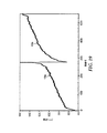
図9Aは、2次反射帯域が1次及び3次反射帯域の少なくとも一方に重複するよう作製され、単一の広くなった反射帯域を生成する場合を図示する。簡単に言えば、ミクロ層積層体は、たくさんの調波反射帯域を提供するよう調整されている。積層体のORU厚さ勾配は、ある範囲の光学的厚さをカバーし、これにより、1次、2次、及び3次反射帯域が図示のようになる。ここで、光は所与の偏光状態で、設計入射角(例えば垂直入射)であると仮定される。説明を簡単にするために、図中の反射帯域はすべて、単純化又は理想化して、すなわち長方形で図示されている。ミクロ層積層体のf比は0.25である。図5Aにより、このf比は1次、2次、及び3次調波を生成し、1次の反射能は2次の反射能と同じであり、3次はこれより低いがゼロではない反射能を有する。この図において、一般化のため、縦の「反射率」軸には目盛は提供されていない。ただし、1次及び2次帯域がほぼ同じ反射率を有し、3次帯域が実質的に低減された反射率を有するという点において、異なる帯域の相対的高さは少なくとも概ね正確である。1次帯域は、左の帯域エッジ800nmから右の帯域エッジ1600nmまで延在する。2次帯域は、左の帯域エッジ400nmから右の帯域エッジ800nmまで延在する。3次帯域は、左の帯域エッジ266nmから右の帯域エッジ533nmまで延在する。3次を超える調波は、単純化のため図示されていない。このように、2次反射帯域は、1次反射帯域及び3次反射帯域と(スペクトル的に)重複している。2次帯域と1次帯域の重複は、2次帯域の右の帯域エッジが、1次帯域の左の帯域エッジに合致する時、又は、2次帯域の右の帯域エッジが1次帯域内になる時(すなわち、2次帯域の右の帯域エッジが1次帯域の左と右の帯域エッジの間にある時)に、確立される。同様に、2次帯域と3次帯域の重複は、2次帯域の左の帯域エッジが、3次帯域の右の帯域エッジに合致する時、又は、2次帯域の左の帯域エッジが3次帯域内になる時(すなわち、2次帯域の左の帯域エッジが3次帯域の左と右の帯域エッジの間にある時)に、確立される。
FIG. 9A illustrates the case where the secondary reflection band is made to overlap at least one of the primary and tertiary reflection bands to produce a single widened reflection band. Briefly, the microlayer stack is tuned to provide a large number of harmonic reflection bands. The stack's ORU thickness gradient covers a range of optical thicknesses, resulting in first, second, and third order reflection bands as shown. Here, light is assumed to be at the design angle of incidence (eg, normal incidence) for a given polarization state. For simplicity of explanation, all reflection bands in the figure are simplified or idealized, ie shown as rectangles. The f-ratio of the microlayer stack is 0.25. According to FIG. 5A, this f-ratio produces first, second, and third order harmonics, with the first order reflectivity being the same as the second order reflectivity and the third order being lower but non-zero reflection. Have the ability. In this figure, for generalization, no scale is provided on the vertical "reflectance" axis. However, the relative heights of the different bands are at least approximately accurate in that the primary and secondary bands have approximately the same reflectivity and the tertiary band has substantially reduced reflectivity. The primary band extends from the
1次、2次、及び3次調波帯域の重複の結果、少なくともこれら3つの調波反射帯域を組み合わせた、単一の広い反射帯域が形成される。同じ偏光状態及び同じ設計入射角について、そのような単一の広い反射帯域が、図9Bに示されている。この帯域は、左の帯域エッジ約266nm(3次帯域の左の帯域エッジに対応)から右の帯域エッジ約1600nm(1次帯域の右の帯域エッジに対応)まで延在して示されている。この広い又は拡張された帯域は、赤外線スペクトル全体と、可視光スペクトルの大半にわたって、比較的一定の反射率をもたらす。ただし、スペクトル400nm近くの、青/紫側では、400〜533nmで、2次と3次の組み合わせによりやや高くなっており、また266〜400nmではかなり低くなっている。 The overlap of the first, second, and third harmonic bands results in the formation of a single broad reflection band that combines at least these three harmonic reflection bands. Such a single broad reflection band for the same polarization state and the same design angle of incidence is shown in FIG. 9B. This band is shown extending from the left band edge of approximately 266 nm (corresponding to the left band edge of the cubic band) to the right band edge of approximately 1600 nm (corresponding to the right band edge of the primary band). . This wide or extended band provides a relatively constant reflectance over the entire infrared spectrum and much of the visible light spectrum. However, in the blue / purple side near 400 nm of the spectrum, it is 400 to 533 nm, which is slightly higher due to the combination of the second and third orders, and is considerably lower in the range of 266 to 400 nm.
本明細書を通して、所与の反射帯域の左の帯域エッジは、短波長帯域エッジとも呼ばれ、この波長はλSと表わすことができる。同様に、所与の反射帯域の右の帯域エッジは、長波長帯域エッジとも呼ばれ、この波長はλLと表わすことができる。本明細書では更に、例えば1次又は2次などの所与の帯域の調波次数を表わすために、追加の下付き文字が使用される。よって例えば、λS1stは1次反射帯域の左の帯域エッジの波長を指し、λL2ndは2次反射帯域の右の帯域エッジの波長を指す。 Throughout this specification, the band edge to the left of a given reflection band is also referred to as the short wavelength band edge, and this wavelength can be designated as λ S. Similarly, the band edge to the right of a given reflection band is also called the long wavelength band edge, and this wavelength can be represented as λ L. Additionally, additional subscripts are used herein to represent the harmonic order of a given band, eg, first or second order. Therefore, for example, λ S1st indicates the wavelength of the band edge on the left of the primary reflection band, and λ L2nd indicates the wavelength of the band edge on the right of the secondary reflection band.
ある反射帯域と別の反射帯域とのスペクトル重複の領域において、反射率は、「コヒーレント」ではなく、「インコヒーレント」に組み合わせられる。例えば、一方の調波帯域が反射率R1を有し、もう一方の調波帯域が同じ波長で反射率R2を有する場合、その波長での積層体全体の反射率Rは、いわゆる「パイルオブプレート」式: In the region of spectral overlap between one reflection band and another, the reflectances are combined "incoherently" rather than "coherently". For example, if one harmonic band has a reflectivity R1 and the other harmonic band has a reflectivity R2 at the same wavelength, the reflectivity R of the entire laminate at that wavelength is the so-called "pile of plate". "formula:
ここで、空気界面の影響に関して、明確にすべき点を説明する。光学フィルム又はフィルム体は、外側前面又は上主表面と、外側背面又は下主表面とを有する。これらの2つの表面はそれぞれ、典型的に、空気、真空、又は別の不活性ガスに曝されている。反射防止膜が提供されている場合を除き、光は、光学フィルムの内部構造又は組成にかかわらず、これら2つの外側表面で反射される。フィルム(又はその構成要素、例えばミクロ層積層体)の反射特性について検討する時、外側表面反射の影響を反射率値に含めるか、あるいは外側表面反射の影響を除外することができる。外側表面反射の影響を含めた反射率値は「外部」反射率と呼ばれ、外側表面反射の影響を含めない反射率値は「内部」反射率と呼ばれる。換言すれば、フィルム又は他の構成体の「内部反射率」は、そのフィルムの前側若しくは後側(又は上若しくは下など)における任意の境界面の非存在下で、空気又はフィルムとは異なる屈折率の任意の他の媒質との接触に起因して、そのフィルムが有する反射率である。「内部透過率」及び「外部透過率」は同様に、ただし透過率について定義される。本明細書の目的のために、別途明示的に記載のない限り、「反射率」及び類似の語は外部反射率を指し、「透過率」及び類似の語は外部反射率を指す。よって例えば、R1及びR2に関して全体の反射率Rのための上記の「パイルオブプレート」式において、R1及びR2が内部反射率について与えられた場合、計算されるRも内部反射率を指す。あるいは、「パイルオブプレート」式は、R1が一方の外側界面での表面反射の影響を含み得、R2が反対側の外側界面での表面反射の影響を含み得るように解釈することができ、ここにおいてRは、フィルムの外側反射率、すなわち、フィルムの両方の外側表面での光反射の影響を含むフィルムの反射率を表わす。 Here, points to be clarified regarding the influence of the air interface will be described. The optical film or film body has an outer front surface or upper main surface and an outer back surface or lower main surface. Each of these two surfaces is typically exposed to air, vacuum, or another inert gas. Light is reflected at these two outer surfaces regardless of the internal structure or composition of the optical film, unless an antireflective coating is provided. When considering the reflective properties of a film (or its components, such as a microlayer stack), the effect of outer surface reflection can be included in the reflectance value or the effect of outer surface reflection can be excluded. Reflectance values that include the effect of outer surface reflection are called "external" reflectance, and reflectivity values that do not include the effect of outer surface reflection are called "internal" reflectance. In other words, the "internal reflectance" of a film or other construct is the difference in refraction from air or film in the absence of any interface on the front or back (or top, bottom, etc.) of the film. The reflectivity that the film has due to its contact with any other medium of index. "Internal transmittance" and "external transmittance" are defined similarly, but in terms of transmittance. For purposes of this specification, unless otherwise explicitly stated, "reflectance" and like terms refer to external reflectance, and "transmittance" and similar terms refer to external reflectance. So, for example, in the above "pile of plate" equation for the total reflectance R with respect to R1 and R2, if R1 and R2 are given for internal reflectance, then the calculated R also refers to internal reflectance. Alternatively, the "pile of plate" equation can be interpreted such that R1 can include the effect of surface reflection at one outer interface and R2 can include the effect of surface reflection at the opposite outer interface, Where R represents the outer reflectance of the film, ie the reflectance of the film including the effects of light reflection on both outer surfaces of the film.
図9Aの反射帯域の単純化により、上記の重複技法が容易に理解できるようになる。しかしながら、上述のように、実際のミクロ層積層体により生成される実際の反射帯域は、理想的な長方形にはなっていない。したがって、反射帯域の左右の帯域エッジの正確な波長が容易に決定できない限り、所与の反射帯域が別の反射帯域と重複しているかどうかの判定はそれほど単純ではない可能性がある。この理由から、ミクロ層積層体により生成される所与の調波次数反射帯域について、左右の帯域エッジのスペクトル位置を確実に決定するための方法を下記に述べる。この方法は、その積層体について、測定又はモデル化されたスペクトル反射率の解析と、測定又はモデル化されたORU厚さプロファイルの解析の両方を含み、更に積層体のf比も解析の要素となる。 The simplification of the reflection band in FIG. 9A makes the above overlapping technique easy to understand. However, as mentioned above, the actual reflection band produced by the actual microlayer stack is not an ideal rectangle. Therefore, the determination of whether a given reflection band overlaps another reflection band may not be so straightforward unless the exact wavelengths of the left and right band edges of the reflection band can be easily determined. For this reason, a method for reliably determining the spectral position of the left and right band edges for a given harmonic order reflection band produced by a microlayer stack is described below. This method includes both the analysis of the measured or modeled spectral reflectance and the analysis of the measured or modeled ORU thickness profile for the stack, and also the f-ratio of the stack as an element of the analysis. Become.
実際のミクロ層積層体により生成される実際の反射帯域が理想的な長方形を有していないということは、反射帯域重複の考え方に関して副次的影響を有する。特に、帯域エッジの位置を決定する本明細書の方法に厳密に従えば重複していない2つの反射帯域(例えば、本明細書の方法で決定された短い波長反射帯域の右の帯域エッジが、本明細書の方法で決定された長い波長反射帯域の左の帯域エッジから、わずか数ナノメートルだけ離れていて、それらの帯域が重複しているとはみなされない場合)は、依然として、単一の広い反射帯域として妥当に特徴付けられ得るスペクトル特性を生成するのに、十分近接している可能性がある。そのような状況を考慮して、本出願者らは用語「実質的な重複」(及び「実質的に重複している」などの関連表現)を使用して、(a)上記のように2つの反射帯域の間に実際の重複がある場合と、(b)隣接する反射帯域の2つの近くの帯域エッジの間に実際の重複はないが、一方の帯域の波長(例えばλL2nd)と他方の帯域の波長(例えばλS1st)との差が、いずれかの帯域エッジの波長の5%以下である場合との、両方を包含する。 The fact that the actual reflection band produced by the actual microlayer stack does not have an ideal rectangle has a side effect on the idea of reflection band overlap. In particular, two reflection bands that are not overlapping according to the method of the present invention for determining the position of the band edge (for example, the right band edge of the short wavelength reflection band determined by the method of the present invention is Only a few nanometers away from the band edge to the left of the long wavelength reflection band determined by the method herein (if the bands are not considered overlapping), still remain a single It may be close enough to produce a spectral characteristic that can be reasonably characterized as a wide reflection band. In view of such circumstances, Applicants use the term “substantially overlapping” (and related expressions such as “substantially overlapping”) to (a) There is an actual overlap between two reflection bands, and (b) there is no actual overlap between two nearby band edges of adjacent reflection bands, but one wavelength (eg λ L2nd ) and the other Both the case where the difference from the wavelength of the band (for example, λ S1st ) is 5% or less of the wavelength of any band edge is included.
図10Aは、2次反射帯域が1次及び3次反射帯域の少なくとも一方に重複するよう作製され、単一の広くなった反射帯域を生成する別の場合を図示する。簡単に言えば、ミクロ層積層体は図9Aの積層体と実質的に同様に作製することができるが、ただし、積層体のすべてのORUのf比が、0.25から0.33(すなわち1/3)へと変更されている。図5Aを参照して、改変されたf比は1次及び2次調波を生成するが、3次調波は生成しない。図5Aから更に、2次調波の反射能は、f比が1/3の場合、1次調波の反射能より顕著に小さくなることがわかる(図9Aにおいてほぼ等しいのとは異なる)。図9Aと同様に、図10Aに示されている反射帯域は、所与の偏光状態で、設計入射角(例えば垂直入射)の光に対する、積層体の反射率を表わす。また、一般化のため、図10Aの縦の「反射率」軸には目盛は提供されていない。ただし、2次帯域が1次帯域より顕著に低い反射率を有し、3次帯域が存在しないという点において、異なる帯域の相対的高さは概ね正確である。1次帯域は、左の帯域エッジ800nmから右の帯域エッジ1600nmまで延在する。2次帯域は、左の帯域エッジ400nmから右の帯域エッジ800nmまで延在する。3次帯域は存在せず、3次より上の調波は単純化のため図示されていない。よってこの場合、2次反射帯域は(スペクトル的に)1次反射帯域に重複する。
FIG. 10A illustrates another case where the secondary reflection band is made to overlap at least one of the primary and tertiary reflection bands to produce a single widened reflection band. Briefly, the microlayer stack can be made substantially similar to the stack of FIG. 9A, except that the f-ratio for all ORUs of the stack is 0.25 to 0.33 (ie It has been changed to 1/3). Referring to FIG. 5A, the modified f-ratio produces first and second order harmonics, but not third order harmonics. It can be further seen from FIG. 5A that the reflectivity of the second harmonic is significantly smaller than the reflectivity of the first harmonic when the f ratio is 1/3 (unlike in FIG. 9A, which is almost equal). Similar to FIG. 9A, the reflection band shown in FIG. 10A represents the reflectivity of the stack for light at the design angle of incidence (eg, normal incidence) for a given polarization state. Also, for generalization, no scale is provided on the vertical "reflectance" axis of FIG. 10A. However, the relative heights of the different bands are generally accurate in that the secondary band has a significantly lower reflectivity than the primary band and there is no tertiary band. The primary band extends from the
1次及び2次調波帯域の重複の結果、これら2つの調波反射帯域を組み合わせた、単一の広い反射帯域が形成される。単一の広い反射帯域が図10Bに示されており、これは、図10Aと同じ偏光状態及び同じ設計入射角を想定している。この帯域は、左の帯域エッジ約400nm(2次帯域の左の帯域エッジに対応)から右の帯域エッジ約1600nm(1次帯域の右の帯域エッジに対応)まで延在して示されている。この広い又は拡張された帯域は、赤外線領域の大半にわたって比較的一定の反射率を提供し、また、可視光スペクトルの大半にわたって比較的一定であるが顕著に低いレベルの反射率(実質的に異なる反射率)を提供する。すなわち、広い反射帯域が、反射率と透過率における段状変化を有している。そのような反射特性を備えた多層光学フィルムは、可視光スペクトルのすべて又は大半にわたって部分的反射と部分的透過が望ましい用途(例えば、人間はフィルムを通して物を見ることができるが、赤外線スペクトルの大部分にわたってこれよりずっと高い反射率が望ましい場合)において有用であり得る。 The overlap of the first and second harmonic bands results in the combination of these two harmonic reflection bands into a single wide reflection band. A single wide reflection band is shown in Figure 10B, which assumes the same polarization state and the same design angle of incidence as Figure 10A. This band is shown extending from the left band edge of approximately 400 nm (corresponding to the left band edge of the secondary band) to the right band edge of approximately 1600 nm (corresponding to the right band edge of the primary band). . This wide or extended band provides a relatively constant reflectance over most of the infrared region, and a relatively constant but significantly lower level of reflectance (substantially different) over most of the visible light spectrum. Reflectance). That is, a wide reflection band has step changes in reflectance and transmittance. Multilayer optical films with such reflective properties are used in applications where partial reflection and transmission are desired over all or most of the visible light spectrum (for example, humans can see objects through the film, but much of the infrared spectrum). Can be useful in cases where much higher reflectance over this is desired).
図11Aは、2次反射帯域が1次及び3次反射帯域の少なくとも一方に重複するよう作製され、単一の広くなった反射帯域を生成する更に別の場合を図示する。簡単に言えば、ミクロ層積層体は、たくさんの調波反射帯域を提供するよう調整されている。積層体のORU厚さ勾配は、ある範囲の光学的厚さをカバーし、これにより、1次、2次、及び3次反射帯域(及び4次反射帯域)が図示のようになる。ここで、光は所与の偏光状態で、設計入射角(例えば垂直入射)であると仮定される。ミクロ層積層体のf比は0.59である。図5Aを参照して、このf比は1次、2次、3次、及び4次調波を生成し、2次の反射能は3次の反射能と同じであり、4次の反射能はこれよりわずかに高い反射能を有し、1次は最も高い反射能を有する。一般化のため、図11Aの縦の「反射率」軸には目盛は提供されていない。ただし、異なる帯域の相対的高さは概ね正確である。1次帯域は、左の帯域エッジ1200nmから右の帯域エッジ1800nmまで延在する。2次帯域は、左の帯域エッジ600nmから右の帯域エッジ900nmまで延在する。3次帯域は、左の帯域エッジ400nmから右の帯域エッジ600nmまで延在する。4次帯域は、左の帯域エッジ300nmから右の帯域エッジ450nmまで延在する。4次を超える調波は、単純化のため図示されていない。よってこの場合、2次反射帯域は3次反射帯域に(スペクトル的に)重複しているが、1次反射帯域には重複しておらず、又は実質的にも重複していない。
FIG. 11A illustrates yet another case where the secondary reflection band is made to overlap at least one of the primary and tertiary reflection bands to produce a single widened reflection band. Briefly, the microlayer stack is tuned to provide a large number of harmonic reflection bands. The stack's ORU thickness gradient covers a range of optical thicknesses, resulting in the first, second, and third order reflection bands (and fourth order reflection bands) as shown. Here, light is assumed to be at the design angle of incidence (eg, normal incidence) for a given polarization state. The f ratio of the microlayer stack is 0.59. Referring to FIG. 5A, this f-ratio produces first-order, second-order, third-order, and fourth-order harmonics, the second-order reflectivity is the same as the third-order reflectivity, and the fourth-order reflectivity is Has a slightly higher reflectivity than this, and the first order has the highest reflectivity. For generalization, no scale is provided on the vertical "reflectance" axis of FIG. 11A. However, the relative heights of the different bands are generally accurate. The primary band extends from the
2次及び3次調波帯域の重複(並びに3次及び4次帯域の重複)の結果、少なくともこれら2つの調波反射帯域を組み合わせた、単一の広い反射帯域が形成される。単一の広い反射帯域が図11Bに示されており、これは、図11Aと同じ偏光状態及び同じ設計入射角を想定している。この帯域は、左の帯域エッジ約300nm(4次帯域の左の帯域エッジに対応)から右の帯域エッジ約900nm(2次帯域の右の帯域エッジに対応)まで延在して示されている。広い又は拡張された帯域は、赤外線領域の一部と可視光スペクトルの大半にわたって比較的一定の反射率を提供するが、ただし、450nm以下のスペクトルの青/紫側では、4次帯域の存在により増加している。この実施形態では、2次帯域が1次帯域に重複していない、又は実質的にも重複していないことから、これら2つの帯域の間に通過帯域が形成され、このミクロ層積層体は、広い又は拡張された帯域とは別の、赤外線スペクトルの一部分に1次反射帯域を提供する。 The overlap of the 2nd and 3rd order harmonic bands (and the overlap of the 3rd and 4th order bands) results in the formation of a single broad reflection band that combines at least these two harmonic reflection bands. A single broad reflection band is shown in Figure 11B, which assumes the same polarization state and the same design angle of incidence as in Figure 11A. This band is shown extending from about 300 nm on the left (corresponding to the left band edge of the fourth order band) to about 900 nm on the right band edge (corresponding to the right band edge of the second order band). . The broad or extended band provides a relatively constant reflectance over a portion of the infrared region and much of the visible light spectrum, except that on the blue / violet side of the spectrum below 450 nm, due to the presence of a fourth order band. It has increased. In this embodiment, the secondary zone does not overlap, or does not substantially overlap, the primary zone, so that a passband is formed between these two zones and the microlayer stack has It provides a primary reflection band in a portion of the infrared spectrum that is separate from the broad or extended band.
ここまで、図9A−B(f比0.25)、図10A−B(f比0.33)、及び図11A−B(f比0.59)に関連していくつかの単純化された実施形態を説明してきたように、2次反射帯域を1次及び/又は3次反射帯域(及び所望により更に高次の重複反射帯域)と合わせて単一の広い反射帯域にすることにより、ミクロ層積層体の効率を改善することができる。図9Bの広い反射帯域は、重複する1次、2次、及び3次反射帯域を含む。図10Bの広い反射帯域は、重複する1次及び2次反射帯域を含む。図11Bの広い反射帯域は、重複する2次、3次、及び4次反射帯域を含む。調波次数の特定の組み合わせにより生じる効率が、図12のグラフに示されている。この図は、図5Aと同様、反射能をf比の関数としてプロットしているが、1次(m=1)、2次(m=2)、及び3次(m=3)の曲線のみが含まれている。しかしながら、図12には更に、2つの追加の曲線も含まれており、この1つは、1次及び2次の相対的反射能の合計であり(「1次+2次」)、もう1つは、1次、2次、及び3次の相対的反射能の合計である(「1次+2次+3次」)。効率に関して、これら2つの合計曲線は、特定のf比値範囲にわたって、1次反射帯域単独で提供される最大反射能に比べ、より大きい反射能を提供していることに注意されたい。例えば、f比が0.25〜0.75の範囲にわたって、「1次+2次」曲線は、1次反射帯域単独で提供される最大反射能に比べ、等しい反射能を提供するか(f比値が0.25、0.5、及び0.75の時)、又はより大きい反射能を提供する(f比が0.25〜0.5の間、及び0.5〜0.75の間の時)。更に、f比が約0.175〜0.825の範囲にわたって、「1次+2次+3次」曲線は、1次曲線単独で提供される最大反射能に比べ、等しい反射能を提供するか(終点において)、又はより大きい反射能を提供する。より一般的に言えば、所与のミクロ層積層体の合計の有用な反射能は、積層体の望ましい対象波長範囲において反射する調波次数すべての合計であり、これにより単一の広い反射帯域を形成し、この合計は、1次反射帯域単独で提供される最大反射能よりも大きくなり得る(f=0.5の場合)。少なくとも1次及び/又は3次反射の組み合わせに、2次反射の反射能を繋ぐことにより、この重複調波帯域技法を利用した物品が、所与の数のミクロ層と、ミクロ層間の所与の屈折率差について、改善された屈折率効率を提供し得る。 So far, some simplifications have been made in connection with FIGS. 9A-B (f ratio 0.25), FIGS. 10A-B (f ratio 0.33), and FIGS. 11A-B (f ratio 0.59). As described in the embodiments, by combining the secondary reflection band with the primary and / or tertiary reflection bands (and optionally higher order overlapping reflection bands) into a single wide reflection band, The efficiency of the layer stack can be improved. The wide reflection band of FIG. 9B includes overlapping first, second, and third reflection bands. The broad reflection band of FIG. 10B includes overlapping first and second order reflection bands. The wide reflection band of FIG. 11B includes overlapping second, third, and fourth order reflection bands. The efficiency produced by a particular combination of harmonic orders is shown in the graph of FIG. Similar to FIG. 5A, this figure plots reflectivity as a function of f-ratio, but only first-order (m = 1), second-order (m = 2), and third-order (m = 3) curves. It is included. However, FIG. 12 also includes two additional curves, one of which is the sum of the relative reflectivities of the first and second orders (“first order + second order”) and another Is the sum of the relative reflectivities of the 1st, 2nd, and 3rd orders (“1st order + 2nd order + 3rd order”). With respect to efficiency, it should be noted that these two sum curves provide greater reflectivity over a particular range of f-ratio values than the maximum reflectivity provided by the primary reflection band alone. For example, over a range of f ratios of 0.25 to 0.75, does the "first order + second order" curve provide equal reflectivity compared to the maximum reflectivity provided by the primary reflection band alone (f ratio? Values of 0.25, 0.5, and 0.75) or provide greater reflectivity (f ratio between 0.25 and 0.5, and between 0.5 and 0.75) time). Furthermore, over a range of f ratios of about 0.175 to 0.825, does the "first order + second order + third order" curve provide equal reflectivity compared to the maximum reflectivity provided by the first order curve alone ( At the end point) or greater. More generally, the total useful reflectivity of a given microlayer stack is the sum of all harmonic orders that reflect in the desired wavelength range of interest of the stack, which results in a single wide reflection band. , Which can be greater than the maximum reflectivity provided by the primary reflection band alone (for f = 0.5). By linking the reflectivity of the secondary reflections to the combination of at least the first and / or third order reflections, an article utilizing this overlapping harmonic band technique provides a given number of microlayers and a given number of microlayers between the microlayers. An improved refractive index efficiency may be provided for a refractive index difference of
調波帯域重複技法を用いることにより、図12からわかる効率の改善可能性に加えて、場合によっては他の利点も実現され得る。そのような他の利点には、材料コストの低減、反射率の鋭い段状変化を提供する能力、及び製造しやすさが挙げられる。 By using the harmonic band overlap technique, in addition to the efficiency improvement potential seen in FIG. 12, other benefits may be realized in some cases. Such other advantages include reduced material costs, the ability to provide sharp step changes in reflectance, and manufacturability.
材料コスト低減に関して、ミクロ層積層体のf比は、2次調波帯域を励起させるために、50%以外の値になるよう調整される。f比をこのように選択することにより、積層体中の各ORUが、f比50%の1/4波長積層体に比べ、より少ない「A」材料とより多い「B」材料(又はその逆)から作製される。この状況は、「A」及び「B」材料(例えば異なる透明ポリマー)がかなり異なるコストを有する場合に活用することができる。特に、f比を戦略的に選択して、ミクロ層積層体中のより高価な材料の量を最小限に抑えながら、依然として望ましい反射率及び帯域幅を達成することができる。 For material cost reduction, the f-ratio of the microlayer stack is adjusted to a value other than 50% to excite the second harmonic band. This choice of f-ratio allows each ORU in the stack to have less "A" material and more "B" material (or vice versa) than a quarter wave stack with a 50% f-ratio. ). This situation can be exploited when the "A" and "B" materials (eg different transparent polymers) have significantly different costs. In particular, the f-ratio can be strategically selected to minimize the amount of more expensive material in the microlayer stack while still achieving the desired reflectivity and bandwidth.
反射率の段状変化に関して、ポリマー多層光学フィルムの設計者及びメーカーは、反射率の段状変化を伴う連続的な反射帯域を提供するという問題に直面する。このような問題は、単一のミクロ層積層体の1次反射のみを利用している場合は解決が難しくなり得る。なぜなら、そのような解決策は典型的に、ORU厚さプロファイルの勾配に鋭い変化を必要とし得るからである。本明細書は、積層体が重複調波を有するように調整することによって、そのような段状変化が単一のミクロ層積層体でいかにして提供できるかを説明している。これらの重複調波は、ORU厚さプロファイルの勾配に鋭い変化を提供する必要なしに、単一の連続的反射帯域に、急激な段階状の遷移の、実質的に異なる反射率レベルを提供するよう制御することができる。例えば上述の図9A−B、図10A−B、及び図11A−B、並びに下記の図16A−Cを参照されたい。場合によっては、反射率の段状変化は、実質的に異なる反射率又は反射能を有する重複調波反射帯域を用いることが役に立つ。 With respect to step changes in reflectance, designers and manufacturers of polymeric multilayer optical films face the problem of providing continuous reflection bands with step changes in reflectance. Such problems can be difficult to solve if only primary reflection of a single microlayer stack is utilized. Because such a solution may typically require a sharp change in the slope of the ORU thickness profile. The present specification describes how such a step change can be provided in a single microlayer stack by tuning the stack to have overlapping harmonics. These overlapping harmonics provide a single continuous reflection band with substantially different reflectance levels of abrupt step transitions without having to provide sharp changes in the slope of the ORU thickness profile. Can be controlled. See, for example, Figures 9A-B, 10A-B, and 11A-B above, and Figures 16A-C below. In some cases, a step change in reflectivity helps to use overlapping harmonic reflection bands with substantially different reflectivities or reflectivities.
製造の容易さ関して、ポリマー多層光学フィルムの設計者及びメーカーは、非常に広い連続的反射帯域を提供するという問題に直面する。このような問題は、単一のミクロ層積層体の1次反射のみを利用している場合は解決が難しくなり得る。なぜなら、そのような解決策は、ミクロ層積層体にわたって、過剰なほど大きな厚さ範囲を必要とし得るからである。例えば、1次反射のみを利用して、400〜1600nmの光を反射するよう設計したミクロ層積層体では、最も厚いORUが、最も薄いORUの4倍の厚さを有するようなORU厚さプロファイルが必要となる。しかしながら、例えば図10A又は9Aに示すように、1次及び2次反射の両方を組み合わせて、同じ連続的な広い反射帯域を作製した場合、より穏やかに低減するORU厚さプロファイルを使用することができ、この場合、最も厚いORUは、最も薄いORUの厚さの2倍だけである。この点に関しては、後述の図15A−Cも参照されたい。 With respect to ease of manufacture, designers and manufacturers of polymeric multilayer optical films face the problem of providing a very wide continuous reflection band. Such problems can be difficult to solve if only primary reflection of a single microlayer stack is utilized. Because such a solution may require an excessively large thickness range across the microlayer stack. For example, in a microlayer stack designed to reflect light between 400 and 1600 nm using only first order reflection, the ORU thickness profile such that the thickest ORU has four times the thickness of the thinnest ORU. Is required. However, if both the first and second order reflections are combined to create the same continuous broad reflection band, as shown for example in FIG. 10A or 9A, it is possible to use a more moderately decreasing ORU thickness profile. Yes, in this case the thickest ORU is only twice the thickness of the thinnest ORU. See also FIGS. 15A-C below for this point.
製造の容易さに関するもう1つの検討事項には、短波長(例えば、400nm近く及びこれ以下の可視光スペクトルの青/紫色部分)又は近UV波長領域内の波長で光を反射するのに十分な薄さのミクロ層を作製するという問題が挙げられる。溶融ポリマー材料の交互の層を共押出することにより作製された多層光学フィルムの場合、溶融状態のポリマーの流動不安定性の問題が顕著になり得る。流動不安定性により、押し出された層はますます薄くなり得るためである。例えば、望ましいポリマー「A」及び「B」材料の粘弾性が十分に一致しない場合、「層破断」が起こり得る。本明細書に記述される重複調波を用いた技法は、そのような問題を緩和するのに役立ち得る。なぜなら、2次又は3次などのより高次の調波を使用して、短波長(例えば、可視光の青/紫色及び/又は近UV波長領域)で望ましい反射率を提供することにより、溶融ポリマー層は、1次反射帯域の場合に必要になる厚さよりも、はるかに厚くすることができる(2次の場合は2倍の厚さ、3次の場合は3倍の厚さ、など)。 Another consideration for ease of manufacture is that it is sufficient to reflect light at short wavelengths (eg, the blue / purple portion of the visible light spectrum near and below 400 nm) or in the near UV wavelength range. The problem is to make thin microlayers. For multilayer optical films made by coextruding alternating layers of molten polymeric material, the problem of polymer flow instability in the molten state can be significant. Because of the flow instability, the extruded layer can become thinner and thinner. For example, if the viscoelastic properties of the desired polymer "A" and "B" materials do not match well, "layer breaks" can occur. The techniques with overlapping harmonics described herein can help mitigate such problems. Because the higher order harmonics, such as the second or third order, are used to provide the desired reflectivity at short wavelengths (eg, the blue / purple and / or near UV wavelength region of visible light), the melting The polymer layer can be much thicker than would be needed for the first order reflection band (twice the thickness for the second order, triple the thickness for the third order, etc.). .
モデル化実施例
ここで、本出願者らが光学設計ソフトウェアを使用して設計及びモデル化した特定の具体的な多層光学フィルム実施形態について検討し、本明細書に記述される重複調波の概念をより現実的に示していく。
Modeling Examples We now consider certain specific multilayer optical film embodiments designed and modeled by Applicants using optical design software, and the concept of overlapping harmonics described herein. Will be shown more realistically.
簡単に言うと、第1モデル化ミクロ層積層体は、上述の図9Aと同様に、1次、2次、及び3次反射帯域の重複を提供するよう調整された。この第1モデル化積層体は、276の個別ミクロ層を138のORUに配列し、勾配ORU厚さプロファイルで、f比は0.25を使用した。図13、14A、及び14Bは、第1モデル化積層体に関するものである。図15A、15B、及び15Cは、第1モデル化積層体を第1比較ミクロ層積層体と比較したもので、この該当する反射帯域は2次要素を有さず、ほぼ1次調波のみによって生成されている。第2モデル化ミクロ層積層体は、上述の図10Aと同様に、1次及び2次反射帯域の重複を提供するよう調整された。この第2モデル化積層体は、第1モデル化積層体と同じ数のミクロ層及びORUを使用し、また、同じ勾配ORU厚さプロファイルを使用したが、f比は0.33に変更された。図13、16A、及び16Bは、第2モデル化積層体に関するものである。図16Cは、第2モデル化積層体の修正に関するものであり、ここにおいてf比は0.33から0.36へと変更され、1次と2次の反射帯域の間により大きい反射率差を提供し、これによって、広くなった反射帯域全体の反射スペクトルにおいてより大きな段状変化をもたらしている。第3モデル化ミクロ層積層体は、上述の図11Aと同様に、2次、3次、及び4次反射帯域の重複を提供するよう調整された。この第3モデル化積層体は、第1及び第2モデル化積層体と同じ数のミクロ層及びORUを使用したが、異なる勾配ORU厚さプロファイルを使用した。更に、f比が0.59に変更された。図17、18A、及び18Bは、第3モデル化積層体に関するものである。最後に、図19〜21は第2比較ミクロ層積層体に関するものであり、この2次反射帯域は、積層体の1次と3次反射帯域のいずれとも重複していないか、又は実質的に重複していない。 Briefly, the first modeled microlayer stack was adjusted to provide overlap of the 1 st, 2 nd, and 3 rd order reflection bands, similar to FIG. 9A above. This first modeled laminate used 276 individual microlayers arranged in 138 ORUs, with a gradient ORU thickness profile and an f-ratio of 0.25. 13, 14A, and 14B relate to the first modeled stack. 15A, 15B, and 15C compare the first modeled stack with the first comparative microlayer stack, in which the relevant reflection band has no quadratic elements and is almost exclusively the first harmonic. Is being generated. The second modeled microlayer stack was tuned to provide overlap of the primary and secondary reflection bands, similar to FIG. 10A above. This second modeled laminate used the same number of microlayers and ORUs as the first modeled laminate and also used the same graded ORU thickness profile, but the f-ratio was changed to 0.33. . 13, 16A, and 16B relate to the second modeled stack. FIG. 16C relates to a modification of the second modeled stack, where the f-ratio is changed from 0.33 to 0.36 to produce a larger reflectance difference between the first and second order reflection bands. , Which results in a larger step change in the reflection spectrum across the broadened reflection band. The third modeled microlayer stack was tuned to provide overlap of second, third, and fourth order reflection bands, similar to FIG. 11A above. This third modeled stack used the same number of microlayers and ORUs as the first and second modeled stacks, but a different gradient ORU thickness profile. Furthermore, the f ratio was changed to 0.59. 17, 18A, and 18B relate to a third modeled stack. Finally, Figures 19-21 relate to the second comparative microlayer stack up, where the secondary reflection band does not overlap with either the primary or the tertiary reflection band of the stack or is substantially. There is no overlap.
これらのモデル化された実施例に関連して、本明細書で検討される重複調波特性を実現しているかどうかを判定するために、所与のミクロ層積層体を解析する目的で本出願者らが開発した方法についても検討する。第1の方法は、調波解析方法と呼ばれ、これにより積層体のスペクトル反射率のどの部分がどの調波次数によるものであるか、また、どのスペクトル反射率が、積層体のそれぞれ該当する調波次数に関するものであるかを判定することができる。この方法では、積層体のそれぞれ該当する調波反射帯域を分離することが可能になり、例えば、積層体の1次反射帯域と、積層体の2次反射帯域と、及びその他も、別々に計算しプロットすることができる。第2の方法は、帯域幅解析方法と呼ばれ、これにより、任意の所与の反射帯域の、左右の帯域エッジの波長値を、組織的かつ繰り返し可能な方法で決定することができる。この第2の方法によって、上述のように、2つの所与の反射帯域が重複しているか又は実質的に重複しているかを、繰り返し、曖昧さなしに決定することが可能になる。 In connection with these modeled examples, the present book for the purpose of analyzing a given microlayer stack to determine if it achieves the superharmonic properties discussed herein. We will also consider the method developed by the applicants. The first method is called a harmonic analysis method, whereby which part of the spectral reflectance of the laminate is due to which harmonic order, and which spectral reflectance corresponds to each of the laminates. It can be determined whether it is related to the harmonic order. This method makes it possible to separate the respective harmonic reflection bands of the stack, for example the first reflection band of the stack, the second reflection band of the stack, and others are calculated separately. Can be plotted. The second method is called the bandwidth analysis method, which allows the wavelength values of the left and right band edges of any given reflection band to be determined in a systematic and repeatable manner. This second method allows iterative and unambiguous determination of whether two given reflection bands overlap or substantially overlap, as described above.
調波解析方法
上述のように、この調波解析方法により、所与のミクロ層積層体のスペクトル反射率のどの部分がどの調波次数によるものであるか、また、どのスペクトル反射率が、積層体のそれぞれ該当する調波次数に関するものであるかを判定することができる。この方法を実行するために、ORU厚さプロファイル、積層体のf比、及びミクロ層の実際の屈折率は周知である、測定できる、又は他の方法で決定できると想定する。
Harmonic Analysis Method As described above, this harmonic analysis method determines which part of the spectral reflectance of a given microlayer stack is due to which harmonic order, and which spectral reflectance is It can be determined whether it is for each applicable harmonic order of the body. To perform this method, it is assumed that the ORU thickness profile, the f-ratio of the stack, and the actual index of refraction of the microlayers are known, measurable, or otherwise determined.
多層ポリマー反射体は典型的に、数多くの1/4波長厚さのミクロ層で作製される。より厳密に言えば、1/2波長厚さの光学的繰り返し単位(ORU)を形成する、高屈折率と低屈折率(nH及びnL)のポリマー材料の、数多くの繰り返しペアで作製される。ポリマー積層体中の交互のミクロ層は典型的に、一般的な無機蒸着誘電性積層体に比べ、比較的小さい屈折率差を有し、よって、ポリマー積層体は典型的に、比較的高い屈折率を得るために、より多くのミクロ層を必要とする。必要とされる多数の繰り返しミクロ層によって、高屈折率層と低屈折率層との繰り返しが、屈折率の波形(「屈折率波形」)によって表わされる。これは、屈折率波形のフーリエ表現を用いて評価することができる。急激な境界を有する1/4波長厚さ層のミクロ層積層体が、屈折率矩形波を形成する。そのような積層体のf比が0.5以外の値になるようにされた場合、この層は、非対称屈折率矩形波と呼ばれる波形を形成する。本出願者らは、適宜成形された繰り返し屈折率波形が、ORUの高屈折率材料及び低屈折率材料の「有効屈折率」を用いることにより、1/4波長層の単純矩形波で表わすことができることを見出した。上述のように、ORUは、フィルムの距離の関数として、連続的に変化する屈折率を伴って形成することができる。 Multilayer polymer reflectors are typically made of numerous quarter-wave thick microlayers. More precisely, made of numerous repeating pairs of high and low refractive index (n H and n L ) polymeric materials forming ½ wavelength thick optical repeat units (ORUs). It Alternating microlayers in a polymer stack typically have a relatively small refractive index difference compared to common inorganic vapor deposited dielectric stacks, and thus polymer stacks typically have a relatively high refractive index. More microlayers are needed to get the rate. Due to the large number of repeating microlayers required, the repetition of the high and low index layers is represented by a refractive index waveform (“index waveform”). This can be evaluated using the Fourier representation of the refractive index waveform. Microlayer stacks of quarter-wave thick layers with sharp boundaries form a refractive index square wave. When the f-ratio of such a stack is made to have a value other than 0.5, this layer forms a waveform called an asymmetric index square wave. Applicants show that appropriately shaped repetitive index waveforms are represented by simple rectangular waves in quarter wave layers by using the "effective index" of the high and low index materials of ORU. I found that I can do it. As mentioned above, the ORU can be formed with a continuously varying index of refraction as a function of film distance.
このフーリエ解析は、ミクロ層の間に急激な境界を有さない系に有効である。必要なのは、個々の正弦波の合計として屈折率波形を表わすのに使用されるフーリエ係数である。これは、様々な調波周波数を表わし、この屈折率の振幅は、フーリエ係数cmによって決定される。個々の調波帯域も、矩形波の層プロファイルを使用して計算することができるが、改変された(有効な)屈折率が必要である。出願者らは更に、反射帯域を広げるため、ORUの積層体が厚さ勾配である時に、フーリエ評価が依然として有効であることを見出した。 This Fourier analysis is effective for a system that does not have abrupt boundaries between microlayers. What is needed is the Fourier coefficient used to represent the index waveform as the sum of the individual sine waves. This represents different harmonic frequencies, the amplitude of this index of refraction being determined by the Fourier coefficient cm . Individual harmonic bands can also be calculated using a square wave layer profile, but a modified (effective) index of refraction is required. Applicants have further found that the Fourier evaluation is still valid when the stack of ORUs has a thickness gradient to broaden the reflection band.
実際のミクロ層厚さ及び屈折率値を使用する多層積層体の計算により、屈折率スペクトルが得られ、これは一般に、各調波次数から未知の寄与を受けた、複数の重複する調波帯域の複合物又は組み合わせであり得る。元のミクロ層積層体の反射率に対する、対象の任意の個々の調波次数のレスポンス又は寄与をシミュレーションするために、本出願者らは、様々な有効屈折率セットを使用できることを見出した。これは、対象の調波次数に固有であり、既知の積層体f比と、実際の屈折率差及び、対象の調波次数に固有である様々な有効ORU数に基づくものである。このフーリエ表現は、複雑な繰り返し屈折率波形と、各調波次数の反射帯域を解析するのに、特に有用である。 The calculation of the multilayer stack using the actual microlayer thickness and refractive index values yields a refractive index spectrum, which is generally a number of overlapping harmonic bands with unknown contributions from each harmonic order. Can be a complex or combination of. Applicants have found that various effective refractive index sets can be used to simulate the response or contribution of any individual harmonic order of interest to the reflectivity of the original microlayer stack. This is unique to the harmonic order of interest and is based on the known stack f-ratio, the actual index difference, and the various effective ORU numbers that are unique to the harmonic order of interest. This Fourier representation is particularly useful for analyzing complex repetitive index waveforms and reflection bands for each harmonic order.
下記の実施例は、非対称(すなわち各ORUの一方のミクロ層が1/4波長厚さより薄く、各ORUのもう一方のミクロ層が1/4波長より厚い)のミクロ層積層体を含む。換言すれば、下記の実施例は、f比が0.5ではないミクロ層積層体を含む。そのような非対称積層体は、本明細書において「非対称矩形波積層体」と呼ばれる。非対称積層体は、f比が0.5である対称積層体(高屈折率材料と低屈折率材料の両方が1/4波長厚さである)とは対照的であり得る。上述のように、f比は、本明細書において時に「f」と略され、f=dH *nH/(dH *nH+dL *nL)で与えられる。式中、dは所与のミクロ層の物理的厚さである。非対称矩形波積層体の反射率、特に、対象の任意の単一調波次数の反射率は、元の非対称矩形波積層体の、1/4波長ミクロ層(この有効屈折率は、対象の調波次数のフーリエ係数から計算される)の「有効積層体」を使用することによってモデル化することができる。対象の所与の調波次数について、有効積層体内のORUの数は、元の積層体のORU数の整数倍であり、ここにおいて整数倍とは「m」、すなわち、対象の調波次数の次数自体である。このように、元のミクロ層積層体がN個のORUを有する場合、m次調波次数の反射率を計算するのに使用する有効積層体は、m*N個のORUを有する。このようにして、所与のミクロ層積層体の様々な調波反射帯域が、対象の各調波次数に関連する各有効積層体の個々の反射率計算を行うことによって、別々に特定され得る。 The examples below include asymmetric (ie, one microlayer of each ORU is less than 1/4 wavelength thick and the other microlayer of each ORU is greater than 1/4 wavelength) microlayer stacks. In other words, the examples below include microlayer stacks where the f-ratio is not 0.5. Such asymmetric stacks are referred to herein as "asymmetric square wave stacks." Asymmetric stacks can be in contrast to symmetrical stacks where both f-ratio is 0.5 (both high index and low index materials are quarter wavelength thick). As mentioned above, the f-ratio is sometimes abbreviated herein as "f" and is given by f = d H * n H / (d H * n H + d L * n L ). Where d is the physical thickness of a given microlayer. The reflectivity of the asymmetric square wave stack, in particular the reflectivity of any single harmonic order of interest, is determined by the quarter-wave microlayer of the original asymmetric square wave stack (this effective refractive index is Can be modeled by using the "effective stack" (calculated from the Fourier coefficient of the wave order). For a given harmonic order of interest, the number of ORUs in the effective stack is an integer multiple of the number of ORUs in the original stack, where integer multiple is "m", that is, of the harmonic order of interest. It is the order itself. Thus, if the original microlayer stack has N ORUs, the effective stack used to calculate the reflectivity of the mth harmonic order will have m * N ORUs. In this way, the various harmonic reflection bands of a given microlayer stack can be separately identified by performing individual reflectance calculations for each effective stack associated with each harmonic order of interest. .
フーリエ解析のための有効積層体の有効屈折率差は、元の積層体のピーク間屈折率差と、積層体屈折率プロファイル(すなわち積層体波形)のフーリエ係数cmとを掛け合わせることによって得られる。フーリエ係数cmは図5Aに関連して上記で説明されており、その中で、次のように計算できることが示されている。 The effective refractive index difference of the effective laminated body for the Fourier analysis is obtained by multiplying the peak-to-peak refractive index difference of the original laminated body by the Fourier coefficient cm of the laminated body refractive index profile (that is, the laminated body waveform). To be The Fourier coefficient c m has been described above in connection with FIG. 5A and shows therein that it can be calculated as:
元のミクロ層積層体がN個のORU(2N個のミクロ層)を有する場合、対象の所与の調波次数mの反射帯域は、次数mの有効積層体と、任意の標準多層積層体コンピュータソフトウェアプログラムとを用いて計算することができ、ここにおいて有効積層体に使用する屈折率は、Δneffの式に関連して上述した通りである。有効積層体は、m*N個の光学的繰り返し単位を有する。有効積層体内のORUの光学的厚さは、層プロファイル内のORUのm倍で、元の積層体のORUの厚さの1/m倍である。よって、対象の所与の調波次数mの反射率の計算を実行する際、有効積層体は、元の積層帯内の各ORUを、ORUのそれぞれが、元の積層体の対応するORUの厚さの1/m倍である、m個のORUで置換することによって得られる。実施例を以下に記載する。 Given that the original microlayer stack has N ORUs (2N microlayers), the reflection band of the given harmonic order m of interest is the effective stack of order m and any standard multilayer stacks. Can be calculated using a computer software program, where the refractive index used for the effective stack is as described above in connection with the Δn eff equation. The effective stack has m * N optical repeating units. The optical thickness of the ORU in the effective stack is m times the ORU in the layer profile and 1 / m times the thickness of the ORU in the original stack. Thus, in performing the calculation of the reflectivity for a given harmonic order m of interest, the effective stacks will each ORU in the original stack, each ORU of the corresponding ORU of the original stack. Obtained by substituting m ORUs, which is 1 / m times the thickness. Examples are described below.
帯域幅解析方法
ORUの共振波長は、入射光波の建設的干渉をもたらす層厚さと屈折率の組み合わせとなる波長であり、これによりORUが、入射光に対して部分的に反射性になる。m次反射調波についての、光学的繰り返し単位(ORU)の共振波長は:
Bandwidth Analysis Method The resonant wavelength of the ORU is the wavelength that is the combination of layer thickness and refractive index that results in constructive interference of the incident light wave, which makes the ORU partially reflective to the incident light. The resonant wavelength of the optical repeating unit (ORU) for the mth order reflection harmonic is:
(dH nH+dL nL)は、ORUの光学的厚さであり、上の式を検討すると、1次反射調波はORUの光学的厚さの2倍で生じ、2次反射調波はOURの光学的厚さで生じ、3次反射調波はORUの光学的厚さの2/3で生じ、以下同様になっている。 (D H n H + d L n L ) is the optical thickness of the ORU, and considering the above equation, the first-order reflection harmonic occurs at twice the optical thickness of the ORU, and the second-order reflection harmonic. The wave occurs at the optical thickness of the OUR, and the third-order reflection harmonic occurs at 2/3 of the optical thickness of the ORU, and so on.
ORUのもう1つの光学的特性が、固有帯域幅と呼ばれるものである。固有帯域幅(IBW)は、反射をもたらす建設的干渉に関する、(層積層体内の)隣接するORUの中のコヒーレンス強度の尺度である。ORUは、共振波長だけでなく、ORUの固有帯域幅により決定される共振波長のいずれの側(長波長側及び低波長側)でも、反射率に寄与する。m次反射調波の固有帯域幅は次の式で得られる。 Another optical property of ORUs is called the intrinsic bandwidth. Intrinsic Bandwidth (IBW) is a measure of coherence strength in adjacent ORUs (in a layer stack) for constructive interference that results in reflections. The ORU contributes not only to the resonance wavelength but also to the reflectance on either side of the resonance wavelength (long wavelength side and low wavelength side) determined by the natural bandwidth of the ORU. The natural bandwidth of the mth order reflection harmonic is obtained by the following equation.
IBWmが所与の反射調波次数mと所与のORUのf比について評価される時、そのORUの共振波長を掛けて、部分的帯域幅Δλmを得ることができる。この部分的帯域幅Δλm=IBWm *λ0,mは、そのORU及び他の同様の性質のORUがコヒーレントに作用して反射を生じる波長範囲の尺度である。実際、多数の同一のORUからなるミクロ層積層体(これにより、共通共振波長での反射率は非常に大きく、1又は100%に近い)は、共振波長のいずれかの側にΔλm/2延在する反射帯域を有する。 When IBW m is evaluated for a given reflection harmonic order m and f ratio for a given ORU, it can be multiplied by the resonant wavelength of that ORU to obtain the partial bandwidth Δλ m . This partial bandwidth Δλ m = IBW m * λ 0, m is a measure of the wavelength range over which the ORU and other similar ORUs act coherently to cause reflection. In fact, a microlayer stack consisting of a large number of identical ORUs (which results in very high reflectivity at the common resonance wavelength, close to 1 or 100%) has a Δλ m / 2 on either side of the resonance wavelength. It has an extending reflection band.
ミクロ層積層体内で実質的に単調に薄い層から厚い層への勾配を有して隣接するたくさんのORUが、互いに重複する部分的帯域幅Δλmを有する場合、コヒーレント反射が生成される。実際、任意の所与のORUと、それに伴う共振波長について、隣接するORUの部分的帯域幅Δλmを解析することができ、これにより、所与のORUの共振波長に部分的帯域幅が重複している隣接ORUの数を決定することができる。所与のORUの共振波長に重なる部分的帯域幅を備えたこれらの隣接するORUそれぞれが、所与のORUと共にコヒーレントに作用して、所与のORUの共振波長で反射率を生成する。 Coherent reflections are produced when a number of adjacent ORUs with a gradient from a monotonically thin layer to a thick layer in the microlayer stack have partial bandwidths Δλ m that overlap each other. In fact, for any given ORU and its associated resonant wavelength, the partial bandwidths Δλ m of adjacent ORUs can be analyzed, which results in the partial bandwidth overlapping the resonant wavelength of a given ORU. It is possible to determine the number of neighboring ORUs that are Each of these adjacent ORUs with a partial bandwidth that overlaps the resonant wavelength of a given ORU coherently works with the given ORU to produce reflectance at the resonant wavelength of the given ORU.
この第1原理の論理は、ORU(既知の屈折率値を有する)のモデル化又は測定されたミクロ層積層体が、各ORUの共振波長λ0,mと部分的帯域幅Δλmに関して解析され得る方法を示唆している。各ORUの共振波長について、部分的帯域幅が所与の共鳴波長に重複する隣接するORUの数を数えることができる。この数は、コヒーレント隣接数(CNC)と呼ばれ、所与の共振波長での反射率レベルを決定するのに使用できる。反射率レベルを定量的に決定するには、反射率を、反射率にコヒーレントに寄与するORUの数、及びORU層材料の屈折率値と関連付ける標準式を採用する。 The logic of this first principle is that a modeled or measured microlayer stack of ORUs (with known refractive index values) is analyzed with respect to the resonant wavelength λ 0, m and the partial bandwidth Δλ m of each ORU. Suggests how to get. For each ORU resonant wavelength, the number of adjacent ORUs whose partial bandwidth overlaps a given resonant wavelength can be counted. This number is called the coherent neighbor number (CNC) and can be used to determine the reflectivity level at a given resonant wavelength. To quantitatively determine the reflectivity level, a standard equation is used that relates the reflectivity with the number of ORUs that coherently contribute to the reflectivity and the index value of the ORU layer material.
この方法により、当業者は、測定されたミクロ層積層体厚さ分布を、層材料の既知の屈折率値と共に使用して、任意の次数の反射帯域の波長範囲をマッピングし、更に、所与の反射帯域の短波長開始箇所と、同じ反射帯域の長波長終了箇所とを定量的に定義することができる。 By this method, a person skilled in the art can use the measured microlayer stack thickness distribution together with the known refractive index values of the layer material to map the wavelength range of the reflection band of any order and further It is possible to quantitatively define a short wavelength start point of the reflection band of 1 and a long wavelength end point of the same reflection band.
加えて、上述の解析を実行することにより、当業者は、所与のミクロ層積層体に由来する、様々な次数の、複数の反射帯域の波長範囲を個別に決定することができ、ここにおいて、測定された反射スペクトルは、顕著な反射帯域重複による高反射率の短波長領域を示し、個々の反射帯域調波は解読できない。 In addition, by performing the analysis described above, one of ordinary skill in the art can individually determine the wavelength range of multiple reflection bands of various orders from a given microlayer stack, where The measured reflectance spectrum shows a high reflectance short wavelength region due to significant reflection band overlap, and individual reflection band harmonics cannot be decoded.
この用途の目的のため、本出願者らは、ミクロ層積層体の所与の(m次)調波反射帯域の発生を、最短の共鳴波長λS,m(ここにおいてCNCは、関連する反射帯域ピーク反射率の25%を超えるRm値を提供する)として定義することを選択する。同様に、反射帯域の終了を示す波長を、最長の共鳴波長λL,m(ここにおいてCNCは、関連する反射帯域ピーク反射率の25%を超えるRm値を提供する)として定義する。この方法を使用して、所与の反射帯域の、短波長帯域エッジの波長λSと、長波長帯域エッジの波長λLとを、繰り返し決定することができる。 For the purposes of this application, we have determined the occurrence of a given (mth) harmonic reflection band of a microlayer stack with the shortest resonance wavelength λ S, m (where CNC is the relevant reflection). To provide R m values greater than 25% of the band peak reflectivity). Similarly, the wavelength that marks the end of the reflection band is defined as the longest resonant wavelength λ L, m (where the CNC provides an R m value greater than 25% of the associated reflection band peak reflectivity). This method can be used to iteratively determine the wavelength λ S at the short wavelength band edge and the wavelength λ L at the long wavelength band edge for a given reflection band.
帯域幅解析方法の更なる詳細と説明は、前述の米国特許出願第13/844,664号に見出すことができる。 Further details and explanations of the bandwidth analysis method can be found in the aforementioned US patent application Ser. No. 13 / 844,664.
第1モデル化積層体
第1モデル化積層体を有する多層光学フィルムが設計されモデル化された。この積層体は、N個の低屈折率ミクロ層とN個の高屈折率ミクロ層とを交互に配置して使用し、N個のORUを形成した。ここにおいてNは138であった。各ORUは、低屈折率ミクロ層(材料「B」)のうち1つと、高屈折率ミクロ層(材料「A」)のうち1つから構成された。低屈折率ミクロ層の屈折率nLは1.494であり、高屈折率ミクロ層の屈折率nHは1.65であった。これらの屈折率は、ポリマー干渉フィルターに一般的に使用される材料の代表的なものである。波長に伴う分散は使用せず、これにより、高次の帯域の帯域エッジ波長は、名目上、それぞれの1次帯域エッジ波長の単純整数分割であり、これにより、各帯域内の反射率は、名目上、小さなスペクトル発振以外、一定であった。(実際の材料では、波長に伴う屈折率の変化が、高次の反射帯域の波長位置を若干シフトさせ、反射率も、長波長よりも低波長側で高くなる傾向がある。)第1モデル化積層体と、それに関連する「有効積層体」(個々の高次の反射帯域を計算するのに使用された)は更に、積層体の両側に、厚さ10マイクロメートル、屈折率1.65の「被覆層」を1つずつ有すると想定された。この構成は、押出ポリマー多層積層体で一般的なものである。各被覆層の外側主表面に、空気界面が想定された。
First Modeled Laminate A multilayer optical film having a first modeled laminate was designed and modeled. This stack used N alternating low refractive index microlayers and N high refractive index microlayers to form N ORUs. Here, N was 138. Each ORU consisted of one of the low index microlayers (material "B") and one of the high index microlayers (material "A"). The low refractive index microlayer had a refractive index n L of 1.494, and the high refractive index microlayer had a refractive index n H of 1.65. These indices of refraction are typical of the materials commonly used in polymer interference filters. We do not use wavelength-dependent dispersion, so that the band-edge wavelengths of the higher-order bands are nominally a simple integer division of their respective first-order band-edge wavelengths, so that the reflectance within each band is Nominally constant except for small spectral oscillations. (In an actual material, the change in the refractive index with wavelength causes a slight shift in the wavelength position of the higher-order reflection band, and the reflectance tends to be higher on the low wavelength side than the long wavelength side.) First model The layered stack and its associated "effective stack" (used to calculate the individual higher order reflection bands) also has a thickness of 10 micrometers and a refractive index of 1.65 on each side of the stack. It was assumed to have one "cover layer" of each. This configuration is typical of extruded polymer multilayer laminates. An air interface was assumed on the outer major surface of each coating layer.
ORUは、f比0.25を有するよう設計された。 The ORU was designed to have an f ratio of 0.25.
ORUは更に、勾配厚さプロファイルを呈した。厚さプロファイルは、単純な冪乗則によって定義され、これにより比較的平坦な反射スペクトルを得た(すなわち、1次反射帯域と、存在するそれより高次の各後段の帯域についても同様に、波長に対して実質的に一定の反射率を有していた)。特に、ORUの高屈折率ミクロ層の物理的厚さdHと低屈折率ミクロ層の物理的厚さdLが、次の式によって決定された。 The ORU also exhibited a gradient thickness profile. The thickness profile is defined by a simple power law, which yields a relatively flat reflection spectrum (ie, for the first order reflection band and each higher order post-existing band that exists, It had a substantially constant reflectance with respect to wavelength). In particular, the physical thickness d H of the high refractive index microlayer and the physical thickness d L of the low refractive index microlayer of the ORU were determined by the following equations.
第1モデル化積層体により生成された個々の1次、2次、及び3次反射帯域が、上述の調波解析方法を用いて計算された。これら個々の調波それぞれについて、「有効積層体」が画定され、これにより、その調波次数の反射スペクトルを計算することが可能になった。1次調波の場合、有効積層体はN個のORU(すなわち138)を有し、ORU厚さプロファイルは図13の曲線1310により与えられ、f比は0.5を想定し、フーリエ係数c1に0.70711を使用して、有効屈折率を計算した。2次調波の場合、有効積層体は2N個のORU(すなわち276)を有し、ORU厚さプロファイルは図13の曲線1312により与えられ、f比は0.5を想定し、フーリエ係数c2に0.5を使用して、有効屈折率を計算した。3次調波の場合、有効積層体は3N個のORU(すなわち414)を有し、ORU厚さプロファイルは図13の曲線1314により与えられ、f比は0.5を想定し、フーリエ係数c3に0.235702を使用して、有効屈折率を計算した。これらの有効積層体に対して計算を実施し、図14Aに示す1次、2次、及び3次のスペクトル反射率曲線を得た。
The individual first, second, and third order reflection bands produced by the first modeled stack were calculated using the harmonic analysis method described above. For each of these individual harmonics, an "effective stack" was defined, which made it possible to calculate the reflection spectrum of that harmonic order. For first order harmonics, the effective stack has N ORUs (ie 138), the ORU thickness profile is given by the
次に上述の帯域幅解析方法を使用して、図14Aに示す1次、2次、及び3次反射帯域のそれぞれについて、短波長帯域エッジの波長λS、及び長波長帯域エッジの波長λLを決定した。グラフでは3本の線分が重ね合わせられている。これらの線分はそれぞれ、帯域幅解析方法によって決定された、関連する調波反射帯域の位置を表わす。各線分は、関連する反射帯域の線形表示である。この線分は、「線分表示」の略で「LSR」とラベル付けられ、帯域幅解析方法によって決定された終点により画定されている。よって、各線分LSRは、「S」とラベル付けされた短波長終点(この波長値λSはその反射帯域の左の帯域エッジの波長である)と、「L」とラベル付けされた長波長終点(この波長値λLはその反射帯域の右の帯域エッジの波長である)とを有する。線分LSRを反射スペクトルに重ね合わせることにより、1次、2次、及び3次反射帯域が波長軸のどこに位置するかが容易かつ正確にわかる。この図から、この第1モデル化積層体について、2次反射帯域が1次反射帯域と3次反射帯域の両方に重複していることがわかる。これら調波反射帯域の重複は、図14Bに見られるように、単一の広くなった反射帯域を生成する。図14Bは、調波次数同士の区別を試みない従来型の光学モデル化計算を用いた第1モデル化積層体の計算した反射率をプロットしている。すなわち、これは波長の関数として、積層体の全体の反射率を単に計算しただけである。図14Aと14Bとを比較することによって、図14Bの単一の広い反射帯域が、重複する1次、2次、及び3次反射帯域を含むことがわかる。 Next, using the bandwidth analysis method described above, the wavelength λ S of the short wavelength band edge and the wavelength λ L of the long wavelength band edge for each of the primary, secondary, and tertiary reflection bands shown in FIG. 14A. It was determined. In the graph, three line segments are superposed. Each of these line segments represents the position of the associated harmonic reflection band, as determined by the bandwidth analysis method. Each line segment is a linear representation of the associated reflection band. This line segment is labeled "LSR", which is an abbreviation for "line segment display" and is defined by the end point determined by the bandwidth analysis method. Thus, each line segment LSR has a short wavelength endpoint labeled "S" (this wavelength value λ S is the wavelength of the band edge to the left of its reflection band) and a long wavelength labeled "L". End point (this wavelength value λ L is the wavelength of the band edge to the right of its reflection band). By superimposing the line segment LSR on the reflection spectrum, it is possible to easily and accurately know where the primary, secondary, and tertiary reflection bands are located on the wavelength axis. From this figure it can be seen that for this first modeled stack, the secondary reflection band overlaps both the primary reflection band and the tertiary reflection band. The overlap of these harmonic reflection bands produces a single broadened reflection band, as seen in FIG. 14B. FIG. 14B plots the calculated reflectance of the first modeled stack using a conventional optical modeling calculation that does not attempt to distinguish between harmonic orders. That is, it simply calculates the overall reflectivity of the stack as a function of wavelength. By comparing FIGS. 14A and 14B, it can be seen that the single broad reflection band of FIG. 14B contains overlapping first, second, and third order reflection bands.
第1モデル化積層体に関する関連パラメータを、下記の表にまとめる。 The relevant parameters for the first modeled laminate are summarized in the table below.
図14Bの反射スペクトルは、波長の関数として積層体の全体の反射率を単純な方法で計算する、従来型の光学モデル化ソフトウェアを用いて得た。別の方法として、そのような反射スペクトルは、例えば図14Aに示されるように、個々の調波反射率を光学的に合わせることにより得ることができる。任意の所与の波長で、様々な高次の帯域の付加的な性質は、「パイルオブプレート」反射体の規則に従うことが示されている。ただし、外側の空気界面で生じ得る反射には注意を払う必要がある。この第1モデル化フィルムにおいて、2次調波の合計反射率は、450nm近くで約0.63(又は63%)であり、3次帯域は約0.33(又は33%)である。図14Bのモデル化反射率は、約440〜450nmで、平均反射率約0.676を呈している。図14Bのモデル化光学フィルムは2つの空気界面を有し、一方、別々に計算された2次及び3次調波次数は、組み合わせて合計4つのフィルム/空気界面を有する。これらの2つの空気界面を数学的に除去する必要があり、その上で、上述の「パイルオブプレート」式を使用して、2つの有効積層体の反射率を計算する。これにより、両方の次数の反射率を生成する単一のミクロ層積層体の反射率と比べることができる。余計な空気界面を数学的に除去するには、1つの空気/ポリマー界面の反射率(屈折率1.65)は、「air」としてラベル付けされ、最初に以下の式で計算された。 The reflectance spectrum of FIG. 14B was obtained using conventional optical modeling software, which calculates the total reflectance of the stack as a function of wavelength in a simple manner. Alternatively, such a reflectance spectrum can be obtained by optically combining the individual harmonic reflectances, eg, as shown in FIG. 14A. At any given wavelength, the additional properties of various higher order bands have been shown to follow the rules of a "pile of plates" reflector. However, attention must be paid to possible reflections at the outer air interface. In this first modeled film, the total reflectance of the second harmonic is about 0.63 (or 63%) near 450 nm and the third order band is about 0.33 (or 33%). The modeled reflectance of FIG. 14B is about 440-450 nm, exhibiting an average reflectance of about 0.676. The modeled optical film of FIG. 14B has two air interfaces, while the separately calculated second and third harmonic orders have a combined total of four film / air interfaces. These two air interfaces need to be mathematically removed, and then the "pile of plate" equation above is used to calculate the reflectance of the two effective stacks. This allows comparison with the reflectance of a single microlayer stack producing reflectances of both orders. To mathematically remove the extra air interface, the reflectivity of one air / polymer interface (refractive index 1.65) was labeled as "air" and was first calculated by the formula:
次に、有効な3次フィルム積層体の内部反射率Rintが、以下の式によって計算された。 The internal reflectance, R int , of the effective tertiary film laminate was then calculated by the formula:
図15A、15B、及び15Cにおいて、第1モデル化積層体を第1比較ミクロ層積層体と比較し、この該当する反射帯域は2次要素を有さず、ほぼ1次調波のみによって生成されている。図15Aは、モデル化された反射率を波長の関数としてプロットしている。曲線1510は、図14Bの反射率曲線と同じであり、第1モデル化積層体の全体の反射率を表わす。曲線1512は、第1比較ミクロ層積層体の反射率である。第1比較積層体は、同じN個のORU(138)と、「A」及び「B」ミクロ層に同じ高屈折率及び低屈折率(それぞれ1.65及び1.494)を使用した。ただし、第1比較積層体ではf比0.5を使用し、これは2次反射を生じない。両方の積層体設計は比較的小さいが等しい3次反射帯域を生成し、これは別個にプロットされてはいないが、この追加の反射率は、約400nm〜550nmの波長で観察することができる。この3次の寄与は、2つの積層体設計で等しいため、以下の解析ではこれを無視することにする。
In FIGS. 15A, 15B, and 15C, the first modeled stack is compared to the first comparative microlayer stack, the corresponding reflection band has no quadratic element and is produced by almost only the first harmonic. ing. FIG. 15A plots the modeled reflectance as a function of wavelength.
また、第1比較積層体のORU厚さプロファイルは、第1比較積層体の反射スペクトルを、第1モデル化積層体の反射スペクトルに実質的に合致させるために、第1モデル化積層体のORU厚さプロファイルに対して変化させる必要がある。光学的厚さプロファイルが図15Bにプロットされている。 Also, the ORU thickness profile of the first comparison laminate is the ORU of the first modeling laminate to substantially match the reflection spectrum of the first comparison laminate with the reflection spectrum of the first modeling laminate. It needs to be changed for the thickness profile. The optical thickness profile is plotted in Figure 15B.
この図において、曲線1520は、第1モデル化積層体のORU厚さプロファイルであり、図13の曲線1310と同じである。曲線1522は、第1比較積層体のORU厚さプロファイルである。この図から、2つのことが明らかである。第1に、第1モデル化積層体(曲線1520)は、第1比較積層体(曲線1522)に比べ、ORU厚さプロファイルがより穏やかに低減していることがわかる。実際、最も厚いORUと最も薄いORUとの比は、第1比較積層体では4であるが、第1モデル化積層体ではわずか2である。第2に、第1モデル化積層体は、第1比較積層体よりも概ね厚いORU(及びミクロ層)を使用している。例えば、第1比較積層体の最も薄いORUは厚さ200nmであり、第1モデル化積層体の最も薄いORUは厚さ400nmである。より厚い層と、より穏やかに低減するプロファイルによって、第1モデル化積層体は、上述のように、第1比較積層体よりも製造が容易になり得る。
In this figure, curve 1520 is the ORU thickness profile of the first modeled stack and is the same as
図15Cは図12と同じであるが、ただし、第1ミクロ層積層体(点P1)及び第1比較ミクロ層積層体(点P2)の動作を表わす2つの点がグラフにプロットされている。第1比較積層体は1次反射帯域のみを利用し(「1次」)、f比が0.5であり、ここで点P2は相対的反射能が1.0である。一方、第1モデル化積層体はf比が0.25で動作し、この1次反射の相対的反射能は実質的に消える。しかし、第1モデル化積層体は1次及び2次両方の反射帯域を利用しているため(「1次+2次」)、それに伴う点P2も、相対的反射能が1.0である。 FIG. 15C is the same as FIG. 12, except that two points are plotted on the graph that represent the behavior of the first microlayer stack (point P1) and the first comparative microlayer stack (point P2). The first comparative stack utilizes only the first order reflection band ("first order") and has an f ratio of 0.5, where point P2 has a relative reflectivity of 1.0. On the other hand, the first modeled stack operates at an f-ratio of 0.25, and the relative reflectivity of this primary reflection disappears substantially. However, since the first modeled laminate uses both the first and second order reflection bands (“first order + second order”), the associated point P2 also has a relative reflectivity of 1.0.
第1モデル化積層体と第1比較積層体の比較に関する関連パラメータ(「広帯域1」)を下記の表にまとめる。
The relevant parameters ("
第2モデル化積層体
第2モデル化積層体を有する別の多層光学フィルムが設計されモデル化された。この積層体は、N個の低屈折率ミクロ層とN個の高屈折率ミクロ層とを交互に配置して使用し、N個のORUを形成した。ここにおいてNは138であった。各ORUは、低屈折率ミクロ層(材料「B」)のうち1つと、高屈折率ミクロ層(材料「A」)のうち1つから構成された。低屈折率ミクロ層の屈折率nLは1.494であり、高屈折率ミクロ層の屈折率nHは1.65であった。波長に伴う分散は使用しなかった。第2モデル化積層体と、それに関連する「有効積層体」(個々の高次の反射帯域を計算するのに使用された)は更に、積層体の両側に(多層光学フィルムの一部として)、厚さ10マイクロメートル、屈折率1.65の「被覆層」を1つずつ有すると想定された。各被覆層の外側主表面に、空気界面が想定された。
Second Modeled Laminate Another multilayer optical film with a second modeled laminate was designed and modeled. This stack used N alternating low refractive index microlayers and N high refractive index microlayers to form N ORUs. Here, N was 138. Each ORU consisted of one of the low index microlayers (material "B") and one of the high index microlayers (material "A"). The low refractive index microlayer had a refractive index n L of 1.494, and the high refractive index microlayer had a refractive index n H of 1.65. No dispersion with wavelength was used. The second modeled stack and its associated "effective stack" (used to calculate the individual higher order reflection bands) is further on either side of the stack (as part of a multilayer optical film). , Each having a thickness of 10 micrometers and a refractive index of 1.65. An air interface was assumed on the outer major surface of each coating layer.
ORUは、f比0.33を有するよう設計された。図5Aからわかるように、このf比は、3次調波反射を実質的に生じない。 The ORU was designed to have an f ratio of 0.33. As can be seen in FIG. 5A, this f-ratio produces virtually no third harmonic reflection.
ORUは、第1モデル化積層体と同じ勾配厚さプロファイルを呈した。よって、第2モデル化積層体のORU厚さプロファイルも、図13の曲線1310で示される。
The ORU exhibited the same gradient thickness profile as the first modeled laminate. Thus, the ORU thickness profile for the second modeled stack is also shown by
第2モデル化積層体により生成された個々の1次及び2次反射帯域が、上述の調波解析方法を用いて計算された。これら個々の調波それぞれについて、「有効積層体」が画定され、これにより、その調波次数の反射スペクトルを計算することが可能になった。1次調波の場合、有効積層体はN個のORU(すなわち138)を有し、ORU厚さプロファイルは図13の曲線1310により与えられ、f比は0.5を想定し、フーリエ係数c1に0.860742を使用して、有効屈折率を計算した。2次調波の場合、有効積層体は2N個のORU(すなわち276)を有し、ORU厚さプロファイルは図13の曲線1312により与えられ、f比は0.5を想定し、フーリエ係数c2に0.438153を使用して、有効屈折率を計算した。これらの有効積層体に対して計算を実施し、図16Aに示す1次及び2次のスペクトル反射率曲線を得た。
The individual first and second order reflection bands produced by the second modeled stack were calculated using the harmonic analysis method described above. For each of these individual harmonics, an "effective stack" was defined, which made it possible to calculate the reflection spectrum of that harmonic order. For first order harmonics, the effective stack has N ORUs (ie 138), the ORU thickness profile is given by the
次に上述の帯域幅解析方法を使用して、図16Aに示す1次及び2次反射帯域のそれぞれについて、短波長帯域エッジの波長λS、及び長波長帯域エッジの波長λLを決定した。グラフでは2本の線分が重ね合わせられている。これらの線分はそれぞれ、帯域幅解析方法によって決定された、関連する調波反射帯域の位置を表わす。各線分は関連する反射帯域の線形表示であり、「LSR」とラベル付けされ、短波長終点が「S」、長波長終点が「L」とラベル付けされている。線分LSRを反射スペクトルに重ね合わせることにより、1次及び2次反射帯域が波長軸のどこに位置するかが容易かつ正確にわかる。この図から、この第2モデル化積層体について、2次反射帯域が1次反射帯域に重複している(しかしと3次反射帯域には重複していない)ことがわかる。これら調波反射帯域の重複は、図16Bに見られるように、単一の広くなった反射帯域を生成する。図16Bは、調波次数同士の区別を試みない従来型の光学モデル化計算を用いた第2モデル化積層体の計算した反射率をプロットしている。すなわち、これは波長の関数として、積層体の全体の反射率を単に計算しただけである。図16Aと16Bとを比較することによって、図16Bの単一の広い反射帯域が、重複する1次及び2次反射帯域を含むことがわかる。また、1次及び2次の反射帯域の異なるレベルの反射率により、第2モデル化積層体の全体の反射スペクトルは、反射率における急激な段状変化を有している。これは、滑らかに変化するORU厚さプロファイル(図13の曲線1310)が積層体に使用されているにもかかわらず、そのようになっている。
Next, the wavelength analysis method described above was used to determine the wavelength λ S of the short wavelength band edge and the wavelength λ L of the long wavelength band edge for each of the primary and secondary reflection bands shown in FIG. 16A. In the graph, two line segments are superposed. Each of these line segments represents the position of the associated harmonic reflection band, as determined by the bandwidth analysis method. Each line segment is a linear representation of the associated reflection band, labeled "LSR", with the short wavelength end labeled "S" and the long wavelength end labeled "L". By superimposing the line segment LSR on the reflection spectrum, it is possible to easily and accurately know where the primary and secondary reflection bands are located on the wavelength axis. From this figure it can be seen that for this second modeled stack, the secondary reflection band overlaps the primary reflection band (but not the tertiary reflection band). The overlap of these harmonic reflection bands produces a single broadened reflection band, as seen in FIG. 16B. FIG. 16B plots the calculated reflectance of the second modeled stack using a conventional optical modeling calculation that does not attempt to distinguish between harmonic orders. That is, it simply calculates the overall reflectivity of the stack as a function of wavelength. By comparing FIGS. 16A and 16B, it can be seen that the single broad reflection band of FIG. 16B contains overlapping first and second order reflection bands. Also, due to the different levels of reflectance of the primary and secondary reflection bands, the overall reflectance spectrum of the second modeled stack has a sharp step change in reflectance. This is so even though a smoothly varying ORU thickness profile (
第2モデル化積層体に関する関連パラメータを、下記の表にまとめる。 The relevant parameters for the second modeled laminate are summarized in the table below.
図16Cに関連して、f比を0.33ではなく0.36に変えた場合、第2モデル化積層体がどのように働くかを調べる1.65。曲線1610は第2モデル化積層体の反射率スペクトルであり、すなわち、図16Bに示される反射率スペクトルと同じである。曲線1612は、改変した積層体について計算した反射率スペクトルである。単一の広い反射帯域がここでも生成され、反射率の急激な段状変化を伴っている1.65。曲線1612の段状変化は、曲線1610よりも大きい。これは、900〜1600nm範囲の平均反射率がより高く、450〜800nm範囲の平均反射率がより低いためである。f比を0.33から0.36に増加させたことで、弱い3次レスポンスが生じ、これは、約400〜550nmの波長で、スペクトル1612に検出され得る。
With reference to FIG. 16C, investigate how the second modeled stack works when the f-ratio is changed to 0.36 instead of 0.33 1.65.
第3モデル化積層体
第3モデル化積層体を有する別の多層光学フィルムが設計されモデル化された。この積層体は、N個の低屈折率ミクロ層とN個の高屈折率ミクロ層とを交互に配置して使用し、N個のORUを形成した。ここにおいてNは138であった。各ORUは、低屈折率ミクロ層(材料「B」)のうち1つと、高屈折率ミクロ層(材料「A」)のうち1つから構成された。低屈折率ミクロ層の屈折率nLは1.494であり、高屈折率ミクロ層の屈折率nHは1.65であった。波長に伴う分散は使用しなかった。第3モデル化積層体と、それに関連する「有効積層体」(個々の高次の反射帯域を計算するのに使用された)は更に、積層体の両側に(多層光学フィルムの一部として)、厚さ10マイクロメートル、屈折率1.65の「被覆層」を1つずつ有すると想定された。各被覆層の外側主表面に、空気界面が想定された。
Third Modeled Laminate Another multilayer optical film with a third modeled laminate was designed and modeled. This stack used N alternating low refractive index microlayers and N high refractive index microlayers to form N ORUs. Here, N was 138. Each ORU consisted of one of the low index microlayers (material "B") and one of the high index microlayers (material "A"). The low refractive index microlayer had a refractive index n L of 1.494, and the high refractive index microlayer had a refractive index n H of 1.65. No dispersion with wavelength was used. A third modeled stack and its associated "effective stack" (used to calculate the individual higher order reflection bands) was also provided on each side of the stack (as part of a multilayer optical film). , Each having a thickness of 10 micrometers and a refractive index of 1.65. An air interface was assumed on the outer major surface of each coating layer.
ORUは、f比0.59を有するよう設計された。図5Aからわかるように、このf比は、顕著な1次、2次、3次、及び4次調波反射を生じ、2次及び3調波の反射能は実質的に互いに等しい。 The ORU was designed to have an f ratio of 0.59. As can be seen from FIG. 5A, this f-ratio produces significant first, second, third, and fourth harmonic reflections, and the reflectivities of the second and third harmonics are substantially equal to each other.
ORUは、勾配定数gが1.003であることによって特徴付けられる勾配厚さプロファイルを呈した。更に、開始波長λ0は1215nmが選択された。上述の勾配厚さ式にこれらのパラメータを使用して、図17の曲線1710により示される、第3モデル化積層体のORU厚さプロファイルが得られた。
The ORU exhibited a gradient thickness profile characterized by a gradient constant g of 1.003. Further, the starting wavelength λ 0 was selected to be 1215 nm. Using these parameters in the gradient thickness equation described above, the ORU thickness profile for the third modeled stack, obtained by
第3モデル化積層体により生成された個々の1次、2次、及び3次反射帯域が、上述の調波解析方法を用いて計算された。これら個々の調波それぞれについて、「有効積層体」が画定され、これにより、その調波次数の反射スペクトルを計算することが可能になった。1次調波の場合、有効積層体はN個のORU(すなわち138)を有し、ORU厚さプロファイルは図17の曲線1710により与えられ、f比は0.5を想定し、フーリエ係数c1に0.9603を使用して、有効屈折率を計算した。2次調波の場合、有効積層体は2N個のORU(すなわち276)を有し、ORU厚さプロファイルは図17の曲線1712により与えられ、f比は0.5を想定し、フーリエ係数c2に0.267913を使用して、有効屈折率を計算した。3次調波の場合、有効積層体は3N個のORU(すなわち414)を有し、ORU厚さプロファイルは図17の曲線1714により与えられ、f比は0.5を想定し、フーリエ係数c3に0.220437を使用して、有効屈折率を計算した。これらの有効積層体に対して計算を実施し、図18Aに示す1次、2次、及び3次のスペクトル反射率曲線を得た。
The individual first, second, and third order reflection bands produced by the third modeled stack were calculated using the harmonic analysis method described above. For each of these individual harmonics, an "effective stack" was defined, which made it possible to calculate the reflection spectrum of that harmonic order. For first order harmonics, the effective stack has N ORUs (ie 138), the ORU thickness profile is given by
次に上述の帯域幅解析方法を使用して、図18Aに示す1次、2次、及び3次反射帯域のそれぞれについて、短波長帯域エッジの波長λS、及び長波長帯域エッジの波長λLを決定した。グラフでは3本の線分が重ね合わせられている。これらの線分はそれぞれ、帯域幅解析方法によって決定された、関連する調波反射帯域の位置を表わす。各線分は関連する反射帯域の線形表示であり、「LSR」とラベル付けされ、短波長終点が「S」、長波長終点が「L」とラベル付けされている。線分LSRを反射スペクトルに重ね合わせることにより、1次、2次、及び3次反射帯域が波長軸のどこに位置するかが正確にわかる。このことから、この第3モデル化積層体について、2次反射帯域は1次反射帯域に重複しておらず、3次反射帯域にも重複していないが、3次反射帯域に非常に近いことがわかる。実際、2次帯域の短波長終点Sは626nmにあり、3次帯域の長波長終点Lは597nmにあり、これらの2つの波長の差(29nm)は626nmの5%未満である。よって、第3モデル化積層体の2次及び3次反射帯域は、実質的に重複している。これらの調波反射帯域の実質的な重複(並びに、図示されてはいないが、3次及び4次反射帯域の重複)は、図18Bに見られるように、単一の広くなった反射帯域1810を生成する。図18Bは、調波次数同士の区別を試みない従来型の光学モデル化計算を用いた第3モデル化積層体の計算した反射率をプロットしている。すなわち、これは波長の関数として、積層体の全体の反射率を単に計算しただけである。図18Aと18Bとを比較することによって、図18Bの単一の広い反射帯域1810が、重複する2次及び3次反射帯域を含むことがわかる。急激な段状変化も帯域1810に見られ、これは、3次及び4次の反射帯域の重複によるものである。この急激な段状変化は、滑らかに変化するORU厚さプロファイル(図17の曲線1710)が積層体に使用されているにもかかわらず、反射帯域に存在する。
Next, using the bandwidth analysis method described above, the wavelength λ S of the short wavelength band edge and the wavelength λ L of the long wavelength band edge for each of the primary, secondary, and tertiary reflection bands shown in FIG. 18A. It was determined. In the graph, three line segments are superposed. Each of these line segments represents the position of the associated harmonic reflection band, as determined by the bandwidth analysis method. Each line segment is a linear representation of the associated reflection band, labeled "LSR", with the short wavelength end labeled "S" and the long wavelength end labeled "L". By superimposing the line segment LSR on the reflection spectrum, it is possible to know exactly where the primary, secondary, and tertiary reflection bands are located on the wavelength axis. From this fact, regarding this third modeled laminate, the secondary reflection band does not overlap with the primary reflection band and does not overlap with the tertiary reflection band, but it is very close to the tertiary reflection band. I understand. In fact, the short wavelength end point S of the secondary band is at 626 nm, the long wavelength end point L of the tertiary band is at 597 nm, and the difference between these two wavelengths (29 nm) is less than 5% of 626 nm. Thus, the second and third order reflection bands of the third modeled stack are substantially overlapping. The substantial overlap of these harmonic reflection bands (as well as the overlap of the 3rd and 4th order reflection bands, not shown) results in a single broadened
第3モデル化積層体に関する関連パラメータを、下記の表にまとめる。 The relevant parameters for the third modeled laminate are summarized in the table below.
第2比較ミクロ層積層体
ここで、上述の米国特許出願第13/844,664号の実施例1に述べられている、配向された多層光学フィルムに注目する。この光学フィルムは、2つのアポダイズされたミクロ層積層体を含み、これらは第13/844,664号出願において「パケット1」及び「パケット2」と呼ばれ、光学的に厚いポリマー層で分離されている。本明細書の目的のため、パケット2は本明細書において、第2比較ミクロ層積層体、又は単に第2比較積層体と呼ばれる。2つの積層体はそれぞれ、低屈折率及び高屈折率ポリマーを交互に配置した275層を含み、この高屈折率材料は両積層体とも90/10 coPEN(屈折率1.795)であり、低屈折率材料はパケット1については55/45 coPEN(等方性、屈折率1.605)、パケット2についてはNEOSTAR FN007コポリエステル(屈折率1.505)である。多層光学フィルムの層厚さ値は、原子間力顕微鏡(AFM)を用いて測定され、パケット1及び2の層厚さプロファイル19a及び19bは図19に示されている。
Second Comparative Microlayer Laminates Attention is now directed to the oriented multilayer optical film described in Example 1 of the above-referenced US patent application Ser. No. 13 / 844,664. This optical film comprises two apodized microlayer stacks, referred to in the 13 / 844,664 application as "
図20は、フィルムのブロック軸に沿って、配向された多層光学フィルムの測定透過スペクトルをプロットしている。曲線20aはパケット1のブロック軸スペクトルを表わし、曲線20bはパケット2のブロック軸を表わす。
FIG. 20 plots the measured transmission spectrum of an oriented multilayer optical film along the block axis of the film.
この実施例の延伸ポリマーについて測定された屈折率を、またパケットのORUを画定する測定された層厚さを採用し、光学モデル「スペクトルフィッティング」作業を実施することにより、各パケット内のORUについてf比を変えて、測定されたスペクトルに対する最も良いフィットが見出された。加えて、モデル化スペクトルが測定されたスペクトルに最も合致するように、パケット2の全体的厚さに対する小さな調整が行われた(5%薄くした)。この作業において、パケット1の測定スペクトルは、f比を0.64に仮定した時に最もよく合致し、パケット2の測定スペクトルは、f比を0.62に仮定した時に最もよく合致することが見出された。
Taking the measured refractive index for the stretched polymer of this example, and also the measured layer thickness that defines the ORU of the packet, and performing an optical model "spectral fitting" operation, for the ORU within each packet. The best fit to the measured spectrum was found with varying f-ratio. In addition, small adjustments were made to the overall thickness of packet 2 (5% thinner) so that the modeled spectrum most closely matched the measured spectrum. In this work, we found that the measured spectrum of
この解析により、パケット2(すなわち、第2比較積層体)の関連する特性のモデルが得られ、これから、上述のように、全体の反射率と固有調波反射率を計算することができる。図21の曲線2110は、調波次数同士の区別を試みない従来型の光学モデル化計算を用いた第2比較積層体の計算した反射率をプロットしている。すなわち、これは波長の関数として、積層体の全体の反射率を単に計算しただけである。モデル化パケット2により生成された個々の1次及び2次反射帯域が、上述の調波解析方法を用いて計算された。これら個々の調波それぞれについて、「有効積層体」が画定され、これにより、その調波次数の反射スペクトルを計算することが可能になった。これらの有効積層体に対して計算を行い、1次スペクトル反射率曲線(図21で曲線2112としてプロット)と、2次スペクトル反射率曲線(図21で曲線2114としてプロット)とを得た。次に上述の帯域幅解析方法を使用して、図21に示す1次及び2次反射帯域のそれぞれについて、短波長帯域エッジの波長λS、及び長波長帯域エッジの波長λLを決定した。グラフでは2本の線分が重ね合わせられている。これらの線分はそれぞれ、帯域幅解析方法によって決定された、関連する調波反射帯域の位置を表わす。各線分は関連する反射帯域の線形表示であり、「LSR」とラベル付けされ、短波長終点が「S」、長波長終点が「L」とラベル付けされている。線分LSRを反射スペクトルに重ね合わせることにより、1次及び2次反射帯域が波長軸のどこに位置するかが正確にわかる。この図から、この第2比較積層体について、2次反射帯域が1次反射帯域に重複していないことがわかる。更に、1次及び2次反射帯域の直近の帯域エッジは、互いに5%の範囲内にはない。よって、2次反射帯域は、1次反射帯域に実質的にも重複していない。
This analysis provides a model of the relevant properties of Packet 2 (ie, the second comparative stack) from which the overall reflectance and natural harmonic reflectance can be calculated, as described above.
特に指定されない限り、本明細書及び特許請求の範囲において使用する、数量、特性の測定値などを表す全ての数値は、「約」という語で修飾されるものとして理解されるべきである。したがって、反することが示されない限り、本明細書及び添付「特許請求の範囲」に記載の数値的パラメータは、本願の教示を利用して当業者により得ることが求められる所望の性質に応じて変化する近似値である。特許請求の範囲に対する均等論の適用を制限しようとするものではないが、各数値パラメータは、少なくとも記載される有効桁数を考慮し、更に一般的な四捨五入法を適用することによって解釈されるべきである。本発明の広義の範囲を示す数値的範囲及びパラメータは近似的な値ではあるが、任意の数値が本明細書に述べられる具体例に記載される限りにおいて、これらは妥当な程度に可能な範囲で正確に記載されるものである。しかしながら、いかなる数値も、試験又は測定の限界に伴う誤差を含み得る。 Unless otherwise specified, all numerical values used in the present specification and claims to represent a quantity, a measured value of a property, or the like are to be understood as being modified by the word "about". Therefore, unless indicated to the contrary, the numerical parameters set forth in this specification and the appended claims will vary with the desired properties sought to be obtained by one of ordinary skill in the art using the teachings of the present application. Is an approximate value. While not intending to limit the application of the doctrine of equivalents to the claims, each numerical parameter should be construed by considering at least the number of significant digits stated and applying a more general rounding method. Is. Numerical ranges and parameters showing the broad range of the present invention are approximate values, but as long as arbitrary numerical values are described in the specific examples described herein, these are within a reasonably possible range. It is exactly described in. However, any number may include errors associated with testing or measurement limitations.
本明細書で使用される場合、「頂部」、「底部」、「左」、「右」、「上部」、「下部」、「上方」、「下方」、並びにその他の方向及び配向などの任意の方向は、本明細書において、図を参照する便宜のために使用され、実際のデバイス、物品、又はシステム若しくはその使用を制限しない。本明細書に記載される装置、物品、及びシステムは、様々な方向及び向きで使用されてもよい。 As used herein, any such as "top," "bottom," "left," "right," "top," "bottom," "up," "down," and other directions and orientations. The directions of are used herein for convenience with reference to the figures and do not limit the actual device, article, or system or its use. The devices, articles, and systems described herein may be used in various orientations and orientations.
当業者には、本発明の趣旨及び範囲から逸脱することなく本発明の様々な改変及び変更を行い得ることは明らかであり、本発明は本明細書に記載される例示的な実施形態に限定されない点は理解されるはずである。読者は、1つの開示される実施形態の特徴は、特に断らない限りは他のすべての開示される実施形態にも適用することが可能であると仮定すべきである。本明細書において参照される、米国特許、特許出願公開、並びに他の特許文献及び非特許文献は、これらが上記の開示と矛盾しない限りにおいて参照により援用するものとする。 It will be apparent to those skilled in the art that various modifications and variations of the present invention can be made without departing from the spirit and scope of the invention and that the invention is limited to the exemplary embodiments described herein. It should be understood that it is not done. The reader should assume that features of one disclosed embodiment can be applied to all other disclosed embodiments unless otherwise indicated. All US patents, patent application publications, and other patent and non-patent documents referred to herein are incorporated by reference to the extent they do not contradict the above disclosure.
本明細書は数多くの実施形態を開示し、これには下記が含まれるがこれらに制限されない。
項目1は、光学的繰り返し単位に配置されたミクロ層積層体を含む多層光学フィルムであって、
設計入射角で、該積層体は1次反射帯域、2次反射帯域、及び任意追加的に3次反射帯域を提供し、
該1次反射帯域は、720〜2000nmの波長範囲に少なくとも部分的に配置され、
該2次反射帯域は、380〜720nmの波長範囲に少なくとも部分的に配置され、
該2次反射帯域は、該1次及び3次反射帯域の少なくとも一方に実質的に重複して、単一の広い反射帯域を形成する、フィルム。
This specification discloses numerous embodiments, including, but not limited to, the following.
At the design angle of incidence, the stack provides a first order reflection band, a second order reflection band, and optionally a third order reflection band,
The primary reflection band is located at least partially in the wavelength range of 720 to 2000 nm,
The secondary reflection band is located at least partially in the wavelength range of 380 to 720 nm,
The film wherein the secondary reflection band substantially overlaps at least one of the primary and tertiary reflection bands to form a single broad reflection band.
項目2は、項目1のフィルムであって、前記2次反射帯域が、前記1次反射帯域に実質的に重複し、これにより、前記単一の広い反射帯域が、該1次及び2次反射帯域を含む、フィルム。
項目3は、項目2のフィルムであって、前記2次反射帯域が、前記1次反射帯域に重複する、フィルム。
項目4は、項目2のフィルムであって、前記1次及び2次反射帯域が、実質的に等しい反射率を有する、フィルム。
項目5は、項目4のフィルムであって、前記1次及び2次反射帯域が、違いが10%未満の平均反射率を有する、フィルム。
Item 5 is the film of
項目6は、項目2のフィルムであって、前記1次及び2次反射帯域が、実質的に異なる反射率を有する、フィルム。
Item 6 is the film of
項目7は、項目6のフィルムであって、前記1次及び2次反射帯域が、違いが10%を超える平均反射率を有する、フィルム。 Item 7 is the film of item 6, wherein the primary and secondary reflection bands have an average reflectance of more than 10% difference.
項目8は、項目2のフィルムであって、前記積層体が、前記3次反射帯域を提供しない、フィルム。
項目9は、項目2のフィルムであって、前記積層体が、前記3次反射帯域を提供する、フィルム。
Item 9 is the film of
項目10は、項目9のフィルムであって、前記3次反射帯域が、300〜380nmの波長範囲に少なくとも部分的に配置される、フィルム。
項目11は、項目1のフィルムであって、前記積層体が前記3次反射帯域を提供し、前記2次反射帯域が該3次反射帯域に実質的に重複し、これによって、前記単一の広い反射帯域が、該2次及び3次反射帯域を含む、フィルム。
Item 11 is the film of
項目12は、項目11のフィルムであって、前記2次反射帯域が、前記3次反射帯域に重複する、フィルム。
項目13は、項目11のフィルムであって、前記2次反射帯域が、前記1次反射帯域に実質的に重複せず、これにより、前記単一の広い反射帯域は、該1次反射帯域を含まない、フィルム。 Item 13 is the film of item 11, wherein the secondary reflection band does not substantially overlap the primary reflection band such that the single wide reflection band does not overlap the primary reflection band. Does not include the film.
項目14は、項目11のフィルムであって、前記2次及び3次反射帯域が、実質的に等しい反射率を有する、フィルム。
項目15は、項目14のフィルムであって、前記2次及び3次反射帯域が、違いが10%未満の平均反射率を有する、フィルム。
Item 15 is the film of
項目16は、項目11のフィルムであって、前記2次及び3次反射帯域が、実質的に異なる反射率を有する、フィルム。 Item 16 is the film of item 11, wherein the secondary and tertiary reflection bands have substantially different reflectivities.
項目17は、項目16のフィルムであって、前記2次及び3次反射帯域が、違いが10%を超える平均反射率を有する、フィルム。 Item 17 is the film of item 16, wherein the secondary and tertiary reflection bands have an average reflectance of greater than 10% difference.
項目18は、項目1のフィルムであって、前記2次反射帯域が、380〜720nmの範囲内に少なくとも100nmをカバーする、フィルム。
Item 18 is the film of
項目19は、項目1のフィルムであって、前記単一の広い反射帯域が、反射率の段状変化を有し、前記ミクロ層積層体が、滑らかに変化するORU厚さプロファイルによって特徴付けられる、フィルム。
Item 19 is the film of
項目20は、項目1のフィルムであって、前記2次反射帯域が、300〜380nmの波長範囲に少なくとも部分的に配置される、フィルム。
Claims (2)
設計入射角で、該積層体は1次反射帯域、2次反射帯域、及び任意追加的に3次反射帯域を提供し、
該1次反射帯域は、720〜2000nmの波長範囲内に配置され、
該2次反射帯域は、380〜720nmの波長範囲に少なくとも部分的に配置され、
該積層体の該2次反射帯域は、同じ該積層体の該1次及び3次反射帯域の少なくとも一方に重複する、あるいは、該積層体の該2次反射帯域は、同じ該積層体の該1次及び3次反射帯域の少なくとも一方に重複しないが、該1次反射帯域の短波長帯域エッジと、該2次反射帯域の長波長帯域エッジとの差が、該1次反射帯域の短波長帯域エッジに対して5%以下にある、及び/又は、該2次反射帯域の短波長帯域エッジと、該3次反射帯域の長波長帯域エッジとの差が、該2次反射帯域の短波長帯域エッジに対して5%以下にあり、これにより、単一の広い反射帯域を形成する、フィルム。 A polymeric multilayer optical film comprising a microlayer laminate arranged in optical repeating units, comprising:
At the design angle of incidence, the stack provides a first order reflection band, a second order reflection band, and optionally a third order reflection band,
The primary reflection band is arranged in a wavelength range of 720 to 2000 nm,
The secondary reflection band is located at least partially in the wavelength range of 380 to 720 nm,
The secondary reflection band of the laminate overlaps at least one of the primary and tertiary reflection bands of the same laminate, or the secondary reflection band of the laminate is the same of the same laminate. Although not overlapping at least one of the primary and tertiary reflection bands, the difference between the short wavelength band edge of the primary reflection band and the long wavelength band edge of the secondary reflection band is the short wavelength of the primary reflection band. 5% or less with respect to the band edge, and / or the difference between the short wavelength band edge of the secondary reflection band and the long wavelength band edge of the tertiary reflection band is the short wavelength of the secondary reflection band. A film that is below 5% relative to the band edge, thereby forming a single wide reflection band.
Applications Claiming Priority (3)
| Application Number | Priority Date | Filing Date | Title |
|---|---|---|---|
| US13/866,853 US9279921B2 (en) | 2013-04-19 | 2013-04-19 | Multilayer stack with overlapping harmonics for wide visible-infrared coverage |
| US13/866,853 | 2013-04-19 | ||
| PCT/US2014/033958 WO2014172258A1 (en) | 2013-04-19 | 2014-04-14 | Multilayer stack with overlapping harmonics for wide visible-infrared coverage |
Publications (3)
| Publication Number | Publication Date |
|---|---|
| JP2016520861A JP2016520861A (en) | 2016-07-14 |
| JP2016520861A5 JP2016520861A5 (en) | 2017-05-25 |
| JP6688728B2 true JP6688728B2 (en) | 2020-04-28 |
Family
ID=51728792
Family Applications (1)
| Application Number | Title | Priority Date | Filing Date |
|---|---|---|---|
| JP2016509011A Active JP6688728B2 (en) | 2013-04-19 | 2014-04-14 | Multilayer stack with overlapping harmonics for wide visible / infrared coverage |
Country Status (7)
| Country | Link |
|---|---|
| US (2) | US9279921B2 (en) |
| EP (1) | EP2987008B1 (en) |
| JP (1) | JP6688728B2 (en) |
| KR (1) | KR102185584B1 (en) |
| CN (2) | CN105190381A (en) |
| TW (1) | TWI625558B (en) |
| WO (1) | WO2014172258A1 (en) |
Families Citing this family (22)
| Publication number | Priority date | Publication date | Assignee | Title |
|---|---|---|---|---|
| EP2769247B1 (en) * | 2011-10-20 | 2021-12-01 | 3M Innovative Properties Company | Apodized broadband partial reflectors |
| JP6187211B2 (en) * | 2013-12-06 | 2017-08-30 | 東レ株式会社 | Laminated film |
| US9823395B2 (en) | 2014-10-17 | 2017-11-21 | 3M Innovative Properties Company | Multilayer optical film having overlapping harmonics |
| CN111856635B (en) | 2015-12-18 | 2022-08-09 | 3M创新有限公司 | Broadband visible light reflector |
| US11016229B2 (en) | 2016-06-09 | 2021-05-25 | 3M Innovative Properties Company | Optical filter |
| KR102447243B1 (en) | 2016-07-13 | 2022-09-23 | 쓰리엠 이노베이티브 프로퍼티즈 컴파니 | optical film |
| CN109716208B (en) * | 2016-09-13 | 2022-04-12 | 3M创新有限公司 | Single-packet reflective polarizer with thickness profile tailored for low color at oblique angles |
| WO2018102193A1 (en) * | 2016-11-29 | 2018-06-07 | 3M Innovative Properties Company | Optical stack |
| DE102017203105B4 (en) * | 2017-02-27 | 2019-05-16 | Fraunhofer-Gesellschaft zur Förderung der angewandten Forschung e.V. | Glazing unit, process for their preparation and their use |
| CN113608292B (en) * | 2017-03-06 | 2023-10-03 | 3M创新有限公司 | Optical film |
| JP7259207B2 (en) * | 2017-03-30 | 2023-04-18 | 東レ株式会社 | the film |
| EP3650893A4 (en) * | 2017-07-07 | 2021-04-07 | Toyobo Film Solutions Limited | Multilayer film stack |
| CN107703625B (en) * | 2017-09-27 | 2020-12-01 | 湖北东田光电材料科技有限公司 | Method for judging design correctness of each film layer of broadband antireflection film |
| US11726245B2 (en) | 2017-10-02 | 2023-08-15 | 3M Innovative Properties Company | Partial reflector having stack of polymer layers for correcting color shift |
| JP2021500605A (en) | 2017-10-20 | 2021-01-07 | スリーエム イノベイティブ プロパティズ カンパニー | Optical film and polarizing beam splitter |
| JP2021504761A (en) * | 2017-12-01 | 2021-02-15 | スリーエム イノベイティブ プロパティズ カンパニー | Thin multilayer reflector with uniform left band edge |
| CN111492278B (en) * | 2017-12-20 | 2022-04-26 | 3M创新有限公司 | Optical stack and polarizing beam splitter |
| KR20200115495A (en) * | 2018-01-26 | 2020-10-07 | 쓰리엠 이노베이티브 프로퍼티즈 컴파니 | Multilayer reflective polarizer with crystalline low refractive index layer |
| TWI770362B (en) * | 2018-02-22 | 2022-07-11 | 日商東洋紡股份有限公司 | Multilayer laminated film |
| WO2019244351A1 (en) * | 2018-06-22 | 2019-12-26 | 堺ディスプレイプロダクト株式会社 | Liquid crystal display device and method for producing same |
| KR20220004152A (en) | 2019-05-06 | 2022-01-11 | 쓰리엠 이노베이티브 프로퍼티즈 컴파니 | Patterned Articles Including Electrically Conductive Elements |
| WO2023203390A1 (en) | 2022-04-19 | 2023-10-26 | 3M Innovative Properties Company | Broadband reflectors including polymeric layers, and composite cooling systems |
Family Cites Families (50)
| Publication number | Priority date | Publication date | Assignee | Title |
|---|---|---|---|---|
| US3247392A (en) | 1961-05-17 | 1966-04-19 | Optical Coating Laboratory Inc | Optical coating and assembly used as a band pass interference filter reflecting in the ultraviolet and infrared |
| US3610729A (en) | 1969-06-18 | 1971-10-05 | Polaroid Corp | Multilayered light polarizer |
| US4446305A (en) | 1981-03-02 | 1984-05-01 | Polaroid Corporation | Optical device including birefringent polymer |
| JPS6039602A (en) * | 1983-08-12 | 1985-03-01 | Tokyo Optical Co Ltd | Long-pass filter for far infrared |
| US5486949A (en) | 1989-06-20 | 1996-01-23 | The Dow Chemical Company | Birefringent interference polarizer |
| US5095210A (en) * | 1990-04-06 | 1992-03-10 | The Dow Chemical Company | Multilayer film indicator for determining the integrity or authenticity of an item and process for using same |
| US5103337A (en) | 1990-07-24 | 1992-04-07 | The Dow Chemical Company | Infrared reflective optical interference film |
| US5126880A (en) | 1990-12-18 | 1992-06-30 | The Dow Chemical Company | Polymeric reflective bodies with multiple layer types |
| JP4001619B2 (en) * | 1992-10-29 | 2007-10-31 | スリーエム カンパニー | Moldable reflective multilayer object |
| US5360659A (en) | 1993-05-24 | 1994-11-01 | The Dow Chemical Company | Two component infrared reflecting film |
| JP3971455B2 (en) * | 1993-12-21 | 2007-09-05 | スリーエム カンパニー | Multilayer optical film |
| US5882774A (en) | 1993-12-21 | 1999-03-16 | Minnesota Mining And Manufacturing Company | Optical film |
| JPH08122550A (en) * | 1994-10-20 | 1996-05-17 | Sumitomo Electric Ind Ltd | Waveguide type optical filter |
| US6207260B1 (en) | 1998-01-13 | 2001-03-27 | 3M Innovative Properties Company | Multicomponent optical body |
| US6788463B2 (en) | 1998-01-13 | 2004-09-07 | 3M Innovative Properties Company | Post-formable multilayer optical films and methods of forming |
| US6049419A (en) * | 1998-01-13 | 2000-04-11 | 3M Innovative Properties Co | Multilayer infrared reflecting optical body |
| US6179948B1 (en) | 1998-01-13 | 2001-01-30 | 3M Innovative Properties Company | Optical film and process for manufacture thereof |
| US6157490A (en) * | 1998-01-13 | 2000-12-05 | 3M Innovative Properties Company | Optical film with sharpened bandedge |
| US6808658B2 (en) | 1998-01-13 | 2004-10-26 | 3M Innovative Properties Company | Method for making texture multilayer optical films |
| US6531230B1 (en) | 1998-01-13 | 2003-03-11 | 3M Innovative Properties Company | Color shifting film |
| US6157486A (en) * | 1998-01-13 | 2000-12-05 | 3M Innovative Properties Company | Retroreflective dichroic reflector |
| US6661579B2 (en) * | 2000-01-31 | 2003-12-09 | Pentax Corporation | Beam splitting for camera using a multilayer film |
| JP2001305542A (en) * | 2000-04-26 | 2001-10-31 | Kyocera Corp | Liquid crystal display device |
| KR100905142B1 (en) | 2001-01-15 | 2009-06-29 | 쓰리엠 이노베이티브 프로퍼티즈 컴파니 | Multilayer Infrared Reflecting Film With High and Smooth Transmission in Visible Wavelength Region and Laminate Articles Made Therefrom |
| US7215473B2 (en) | 2002-08-17 | 2007-05-08 | 3M Innovative Properties Company | Enhanced heat mirror films |
| GB2396436B (en) * | 2002-12-19 | 2006-06-28 | Thales Plc | An optical filter |
| US7019905B2 (en) | 2003-12-30 | 2006-03-28 | 3M Innovative Properties Company | Multilayer reflector with suppression of high order reflections |
| CN1556422A (en) * | 2004-01-06 | 2004-12-22 | 同济大学 | Flexible X-ray reflection type multipayer film broad band poarizer and its preparation method |
| US7385763B2 (en) | 2005-04-18 | 2008-06-10 | 3M Innovative Properties Company | Thick film multilayer reflector with tailored layer thickness profile |
| EP1901460A1 (en) * | 2005-08-05 | 2008-03-19 | Matsushita Electric Industrial Co., Ltd. | Wireless communication base station apparatus and wireless communication method in multicarrier communication |
| US7652736B2 (en) | 2005-10-25 | 2010-01-26 | 3M Innovative Properties Company | Infrared light reflecting film |
| US20070097509A1 (en) * | 2005-10-31 | 2007-05-03 | Nevitt Timothy J | Optical elements for high contrast applications |
| JP2007134464A (en) * | 2005-11-09 | 2007-05-31 | Canon Inc | Optical element including multilayer film and exposing apparatus comprising the same |
| GB2432461A (en) * | 2005-11-17 | 2007-05-23 | Marconi Comm Gmbh | T-shape waveguide twist-transformer junction |
| US20080037127A1 (en) * | 2006-03-31 | 2008-02-14 | 3M Innovative Properties Company | Wide angle mirror system |
| US7636193B2 (en) | 2006-05-02 | 2009-12-22 | 3M Innovative Properties Company | Visible light-transmissive IR filter with distorted portions |
| JP5336475B2 (en) | 2007-05-20 | 2013-11-06 | スリーエム イノベイティブ プロパティズ カンパニー | Optical recycling hollow cavity type display backlight |
| KR20100113513A (en) * | 2007-12-10 | 2010-10-21 | 리서치 파운데이션 오브 더 시티 유니버시티 오브 뉴욕 | Sub-wavelength structures, devices and methods for light control in material composites |
| JP5133356B2 (en) * | 2008-01-23 | 2013-01-30 | パナソニック株式会社 | Wavelength separation device, planar illumination device using the same, and liquid crystal display device using the same |
| CN102016659B (en) * | 2008-03-31 | 2014-04-23 | 3M创新有限公司 | Low layer count reflective polarizer with optimized gain |
| CN102016656A (en) * | 2008-04-02 | 2011-04-13 | 3M创新有限公司 | Methods and systems for fabricating optical films having superimposed features |
| TW201020594A (en) | 2008-11-24 | 2010-06-01 | quan-kun Wei | Multi-layer optical film capable of adjusting reflection bands and its manufacturing method |
| EP2373725A4 (en) * | 2008-12-22 | 2017-07-26 | 3M Innovative Properties Company | Multilayer optical films having side-by-side mirror/polarizer zones |
| TWI410712B (en) | 2009-01-13 | 2013-10-01 | Ind Tech Res Inst | Optical film |
| CN102576113B (en) * | 2009-10-24 | 2014-12-17 | 3M创新有限公司 | Immersed asymmetric reflector with reduced color |
| US9162406B2 (en) | 2010-05-07 | 2015-10-20 | 3M Innovative Properties Company | Feedblock for manufacturing multilayer polymeric films |
| CN102906605B (en) * | 2010-05-21 | 2016-02-03 | 3M创新有限公司 | There is the partially reflective multi-layer optical film of the colour of reduction |
| JP5867203B2 (en) * | 2011-03-29 | 2016-02-24 | 東レ株式会社 | Multilayer laminated film, window member using the same, and laminated glass |
| KR101971754B1 (en) | 2011-10-20 | 2019-04-23 | 쓰리엠 이노베이티브 프로퍼티즈 컴파니 | Apodized broadband partial reflectors having differing optical packets |
| US9823395B2 (en) * | 2014-10-17 | 2017-11-21 | 3M Innovative Properties Company | Multilayer optical film having overlapping harmonics |
-
2013
- 2013-04-19 US US13/866,853 patent/US9279921B2/en active Active
-
2014
- 2014-04-14 EP EP14785174.5A patent/EP2987008B1/en active Active
- 2014-04-14 CN CN201480021423.XA patent/CN105190381A/en active Pending
- 2014-04-14 WO PCT/US2014/033958 patent/WO2014172258A1/en active Application Filing
- 2014-04-14 KR KR1020157032544A patent/KR102185584B1/en active IP Right Grant
- 2014-04-14 CN CN202010036836.2A patent/CN111158071B/en active Active
- 2014-04-14 JP JP2016509011A patent/JP6688728B2/en active Active
- 2014-04-18 TW TW103114280A patent/TWI625558B/en not_active IP Right Cessation
-
2016
- 2016-02-19 US US15/048,077 patent/US9678252B2/en active Active
Also Published As
| Publication number | Publication date |
|---|---|
| KR20150143716A (en) | 2015-12-23 |
| CN105190381A (en) | 2015-12-23 |
| US9678252B2 (en) | 2017-06-13 |
| US9279921B2 (en) | 2016-03-08 |
| CN111158071A (en) | 2020-05-15 |
| EP2987008B1 (en) | 2021-05-26 |
| CN111158071B (en) | 2022-02-25 |
| US20140313572A1 (en) | 2014-10-23 |
| TW201447403A (en) | 2014-12-16 |
| TWI625558B (en) | 2018-06-01 |
| US20160170101A1 (en) | 2016-06-16 |
| KR102185584B1 (en) | 2020-12-02 |
| EP2987008A4 (en) | 2016-11-30 |
| JP2016520861A (en) | 2016-07-14 |
| EP2987008A1 (en) | 2016-02-24 |
| WO2014172258A1 (en) | 2014-10-23 |
Similar Documents
| Publication | Publication Date | Title |
|---|---|---|
| JP6688728B2 (en) | Multilayer stack with overlapping harmonics for wide visible / infrared coverage | |
| US9562996B2 (en) | Multilayer stack combinations with interleaved overlapping harmonics for wide visible infrared coverage | |
| JP2017534076A (en) | Multilayer optical film with overlapping harmonics | |
| TWI574058B (en) | Apodized broadband partial reflectors | |
| KR101775746B1 (en) | Partially reflecting multilayer optical films with reduced color | |
| JP7386165B2 (en) | Partial reflector to correct color shift |
Legal Events
| Date | Code | Title | Description |
|---|---|---|---|
| A521 | Request for written amendment filed |
Free format text: JAPANESE INTERMEDIATE CODE: A523 Effective date: 20170404 |
|
| A621 | Written request for application examination |
Free format text: JAPANESE INTERMEDIATE CODE: A621 Effective date: 20170404 |
|
| A131 | Notification of reasons for refusal |
Free format text: JAPANESE INTERMEDIATE CODE: A131 Effective date: 20180206 |
|
| A601 | Written request for extension of time |
Free format text: JAPANESE INTERMEDIATE CODE: A601 Effective date: 20180502 |
|
| A521 | Request for written amendment filed |
Free format text: JAPANESE INTERMEDIATE CODE: A523 Effective date: 20180517 |
|
| A131 | Notification of reasons for refusal |
Free format text: JAPANESE INTERMEDIATE CODE: A131 Effective date: 20181023 |
|
| A601 | Written request for extension of time |
Free format text: JAPANESE INTERMEDIATE CODE: A601 Effective date: 20190122 |
|
| A521 | Request for written amendment filed |
Free format text: JAPANESE INTERMEDIATE CODE: A523 Effective date: 20190220 |
|
| A131 | Notification of reasons for refusal |
Free format text: JAPANESE INTERMEDIATE CODE: A131 Effective date: 20190716 |
|
| RD03 | Notification of appointment of power of attorney |
Free format text: JAPANESE INTERMEDIATE CODE: A7423 Effective date: 20190725 |
|
| RD04 | Notification of resignation of power of attorney |
Free format text: JAPANESE INTERMEDIATE CODE: A7424 Effective date: 20190801 |
|
| A521 | Request for written amendment filed |
Free format text: JAPANESE INTERMEDIATE CODE: A523 Effective date: 20191015 |
|
| A131 | Notification of reasons for refusal |
Free format text: JAPANESE INTERMEDIATE CODE: A131 Effective date: 20191126 |
|
| A521 | Request for written amendment filed |
Free format text: JAPANESE INTERMEDIATE CODE: A523 Effective date: 20200203 |
|
| TRDD | Decision of grant or rejection written | ||
| A01 | Written decision to grant a patent or to grant a registration (utility model) |
Free format text: JAPANESE INTERMEDIATE CODE: A01 Effective date: 20200310 |
|
| A61 | First payment of annual fees (during grant procedure) |
Free format text: JAPANESE INTERMEDIATE CODE: A61 Effective date: 20200406 |
|
| R150 | Certificate of patent or registration of utility model |
Ref document number: 6688728 Country of ref document: JP Free format text: JAPANESE INTERMEDIATE CODE: R150 |
|
| R250 | Receipt of annual fees |
Free format text: JAPANESE INTERMEDIATE CODE: R250 |
|
| R250 | Receipt of annual fees |
Free format text: JAPANESE INTERMEDIATE CODE: R250 |