JP6686943B2 - Electronic key for vehicle - Google Patents
Electronic key for vehicle Download PDFInfo
- Publication number
- JP6686943B2 JP6686943B2 JP2017050298A JP2017050298A JP6686943B2 JP 6686943 B2 JP6686943 B2 JP 6686943B2 JP 2017050298 A JP2017050298 A JP 2017050298A JP 2017050298 A JP2017050298 A JP 2017050298A JP 6686943 B2 JP6686943 B2 JP 6686943B2
- Authority
- JP
- Japan
- Prior art keywords
- vehicle
- electronic key
- vibration
- control unit
- vibration detection
- Prior art date
- Legal status (The legal status is an assumption and is not a legal conclusion. Google has not performed a legal analysis and makes no representation as to the accuracy of the status listed.)
- Active
Links
- 230000001133 acceleration Effects 0.000 claims description 70
- 238000001514 detection method Methods 0.000 claims description 66
- 230000004044 response Effects 0.000 claims description 35
- 238000000034 method Methods 0.000 description 55
- 230000008569 process Effects 0.000 description 49
- 238000012795 verification Methods 0.000 description 37
- 238000012545 processing Methods 0.000 description 36
- 238000004891 communication Methods 0.000 description 10
- 230000005540 biological transmission Effects 0.000 description 7
- 230000006870 function Effects 0.000 description 6
- 230000007246 mechanism Effects 0.000 description 5
- 238000010586 diagram Methods 0.000 description 4
- 230000008859 change Effects 0.000 description 3
- 238000013459 approach Methods 0.000 description 2
- 230000006872 improvement Effects 0.000 description 2
- 230000004048 modification Effects 0.000 description 2
- 238000012986 modification Methods 0.000 description 2
- 230000004043 responsiveness Effects 0.000 description 2
- 239000000284 extract Substances 0.000 description 1
- 230000009467 reduction Effects 0.000 description 1
- 230000008054 signal transmission Effects 0.000 description 1
Images


Classifications
-
- E—FIXED CONSTRUCTIONS
- E05—LOCKS; KEYS; WINDOW OR DOOR FITTINGS; SAFES
- E05B—LOCKS; ACCESSORIES THEREFOR; HANDCUFFS
- E05B47/00—Operating or controlling locks or other fastening devices by electric or magnetic means
- E05B47/0001—Operating or controlling locks or other fastening devices by electric or magnetic means with electric actuators; Constructional features thereof
-
- E—FIXED CONSTRUCTIONS
- E05—LOCKS; KEYS; WINDOW OR DOOR FITTINGS; SAFES
- E05B—LOCKS; ACCESSORIES THEREFOR; HANDCUFFS
- E05B19/00—Keys; Accessories therefor
-
- G—PHYSICS
- G07—CHECKING-DEVICES
- G07C—TIME OR ATTENDANCE REGISTERS; REGISTERING OR INDICATING THE WORKING OF MACHINES; GENERATING RANDOM NUMBERS; VOTING OR LOTTERY APPARATUS; ARRANGEMENTS, SYSTEMS OR APPARATUS FOR CHECKING NOT PROVIDED FOR ELSEWHERE
- G07C9/00—Individual registration on entry or exit
- G07C9/00174—Electronically operated locks; Circuits therefor; Nonmechanical keys therefor, e.g. passive or active electrical keys or other data carriers without mechanical keys
- G07C9/00309—Electronically operated locks; Circuits therefor; Nonmechanical keys therefor, e.g. passive or active electrical keys or other data carriers without mechanical keys operated with bidirectional data transmission between data carrier and locks
-
- G—PHYSICS
- G07—CHECKING-DEVICES
- G07C—TIME OR ATTENDANCE REGISTERS; REGISTERING OR INDICATING THE WORKING OF MACHINES; GENERATING RANDOM NUMBERS; VOTING OR LOTTERY APPARATUS; ARRANGEMENTS, SYSTEMS OR APPARATUS FOR CHECKING NOT PROVIDED FOR ELSEWHERE
- G07C9/00—Individual registration on entry or exit
- G07C9/00174—Electronically operated locks; Circuits therefor; Nonmechanical keys therefor, e.g. passive or active electrical keys or other data carriers without mechanical keys
- G07C9/00571—Electronically operated locks; Circuits therefor; Nonmechanical keys therefor, e.g. passive or active electrical keys or other data carriers without mechanical keys operated by interacting with a central unit
-
- E—FIXED CONSTRUCTIONS
- E05—LOCKS; KEYS; WINDOW OR DOOR FITTINGS; SAFES
- E05B—LOCKS; ACCESSORIES THEREFOR; HANDCUFFS
- E05B47/00—Operating or controlling locks or other fastening devices by electric or magnetic means
- E05B2047/0048—Circuits, feeding, monitoring
- E05B2047/0071—Connecting lockparts by electronic communication means only, e.g. bus systems, time multiplexing
-
- E—FIXED CONSTRUCTIONS
- E05—LOCKS; KEYS; WINDOW OR DOOR FITTINGS; SAFES
- E05B—LOCKS; ACCESSORIES THEREFOR; HANDCUFFS
- E05B47/00—Operating or controlling locks or other fastening devices by electric or magnetic means
- E05B2047/0094—Mechanical aspects of remotely controlled locks
- E05B2047/0095—Mechanical aspects of locks controlled by telephone signals, e.g. by mobile phones
-
- G—PHYSICS
- G07—CHECKING-DEVICES
- G07C—TIME OR ATTENDANCE REGISTERS; REGISTERING OR INDICATING THE WORKING OF MACHINES; GENERATING RANDOM NUMBERS; VOTING OR LOTTERY APPARATUS; ARRANGEMENTS, SYSTEMS OR APPARATUS FOR CHECKING NOT PROVIDED FOR ELSEWHERE
- G07C9/00—Individual registration on entry or exit
- G07C9/00174—Electronically operated locks; Circuits therefor; Nonmechanical keys therefor, e.g. passive or active electrical keys or other data carriers without mechanical keys
- G07C9/00309—Electronically operated locks; Circuits therefor; Nonmechanical keys therefor, e.g. passive or active electrical keys or other data carriers without mechanical keys operated with bidirectional data transmission between data carrier and locks
- G07C2009/00365—Electronically operated locks; Circuits therefor; Nonmechanical keys therefor, e.g. passive or active electrical keys or other data carriers without mechanical keys operated with bidirectional data transmission between data carrier and locks in combination with a wake-up circuit
- G07C2009/0038—Electronically operated locks; Circuits therefor; Nonmechanical keys therefor, e.g. passive or active electrical keys or other data carriers without mechanical keys operated with bidirectional data transmission between data carrier and locks in combination with a wake-up circuit whereby the wake-up circuit is situated in the keyless data carrier
-
- G—PHYSICS
- G07—CHECKING-DEVICES
- G07C—TIME OR ATTENDANCE REGISTERS; REGISTERING OR INDICATING THE WORKING OF MACHINES; GENERATING RANDOM NUMBERS; VOTING OR LOTTERY APPARATUS; ARRANGEMENTS, SYSTEMS OR APPARATUS FOR CHECKING NOT PROVIDED FOR ELSEWHERE
- G07C9/00—Individual registration on entry or exit
- G07C9/00174—Electronically operated locks; Circuits therefor; Nonmechanical keys therefor, e.g. passive or active electrical keys or other data carriers without mechanical keys
- G07C9/00309—Electronically operated locks; Circuits therefor; Nonmechanical keys therefor, e.g. passive or active electrical keys or other data carriers without mechanical keys operated with bidirectional data transmission between data carrier and locks
- G07C2009/00388—Electronically operated locks; Circuits therefor; Nonmechanical keys therefor, e.g. passive or active electrical keys or other data carriers without mechanical keys operated with bidirectional data transmission between data carrier and locks code verification carried out according to the challenge/response method
- G07C2009/00404—Electronically operated locks; Circuits therefor; Nonmechanical keys therefor, e.g. passive or active electrical keys or other data carriers without mechanical keys operated with bidirectional data transmission between data carrier and locks code verification carried out according to the challenge/response method starting with prompting the lock
-
- G—PHYSICS
- G07—CHECKING-DEVICES
- G07C—TIME OR ATTENDANCE REGISTERS; REGISTERING OR INDICATING THE WORKING OF MACHINES; GENERATING RANDOM NUMBERS; VOTING OR LOTTERY APPARATUS; ARRANGEMENTS, SYSTEMS OR APPARATUS FOR CHECKING NOT PROVIDED FOR ELSEWHERE
- G07C9/00—Individual registration on entry or exit
- G07C9/00174—Electronically operated locks; Circuits therefor; Nonmechanical keys therefor, e.g. passive or active electrical keys or other data carriers without mechanical keys
- G07C2009/00753—Electronically operated locks; Circuits therefor; Nonmechanical keys therefor, e.g. passive or active electrical keys or other data carriers without mechanical keys operated by active electrical keys
- G07C2009/00769—Electronically operated locks; Circuits therefor; Nonmechanical keys therefor, e.g. passive or active electrical keys or other data carriers without mechanical keys operated by active electrical keys with data transmission performed by wireless means
- G07C2009/00793—Electronically operated locks; Circuits therefor; Nonmechanical keys therefor, e.g. passive or active electrical keys or other data carriers without mechanical keys operated by active electrical keys with data transmission performed by wireless means by Hertzian waves
Description
本発明は、車両用電子キーに関する。 The present invention relates to a vehicle electronic key.
特許文献1に記載されている電子キーは、加速度センサを備えており、加速度センサが検出した加速度が一定値以上であることに基づいて応答許可状態とする。応答許可状態は、車載機から送信されるリクエスト信号に対する応答が許可された状態である。応答許可状態でリクエスト信号を受信すると、電子キーはレスポンス信号を送信する。応答許可状態でない状態は応答禁止状態である。応答禁止状態では、リクエスト信号に対して応答しない。一定値以上の加速度を検出していない状態が継続したことに基づいて応答禁止状態とする。応答禁止状態であれば、リクエスト信号に対して応答しないので、消費電力が低減する。
The electronic key described in
特許文献1では、加速度センサは、加速度を検出する毎に、検出した加速度を示す信号を電子キー制御部に出力している。加速度センサが検出した加速度を示す信号を電子キーに出力し、その信号を電子キー制御部が認識する際には電力を消費するので、消費電力低減の観点では改良が望まれる。
In
本発明は、この事情に基づいて成されたものであり、その目的とするところは、消費電力をより低減できる車両用電子キーを提供することにある。 The present invention has been made based on this situation, and an object thereof is to provide an electronic key for a vehicle, which can further reduce power consumption.
上記目的は独立請求項に記載の特徴の組み合わせにより達成され、また、下位請求項は、発明の更なる有利な具体例を規定する。特許請求の範囲に記載した括弧内の符号は、一つの態様として後述する実施形態に記載の具体的手段との対応関係を示すものであって、本発明の技術的範囲を限定するものではない。 The above objective is achieved by a combination of features described in independent claims, and the subclaims define further advantageous embodiments of the invention. The reference numerals in parentheses in the claims indicate the correspondence with the specific means described in the embodiments described later as one aspect, and do not limit the technical scope of the present invention. .
上記目的を達成するための本発明は、車両に搭載されている車載機が送信するリクエスト信号を受信するための受信部(21)と、
リクエスト信号に応答するレスポンス信号を送信する送信部(22)と、
受信部からの信号に基づいてリクエスト信号を受信したか否かを判断し、リクエスト信号を受信したと判断したことに基づいて、送信部からレスポンス信号を送信させるキー制御部(26)とを備えた車両用電子キーであって、
車両用電子キーに生じる加速度を検出し、検出した加速度から、閾値以上の振動を検出したと判断したことに基づいて、振動検出フラグをセットする加速度センサ(25)を備え、
キー制御部は、振動検出フラグを、加速度センサが振動検出フラグをセットする周期よりも長い周期に設定されたフラグ読み出し周期ごとに読み出し、振動検出フラグがセットされていることに基づいてリクエスト信号に応答する応答許可状態とする。
MEANS TO SOLVE THE PROBLEM This invention for achieving the said objective is the receiving part (21) for receiving the request signal which the onboard equipment mounted in the vehicle transmits,
A transmission unit (22) for transmitting a response signal in response to the request signal,
A key control unit (26) for determining whether or not a request signal is received based on a signal from the receiving unit and transmitting a response signal from the transmitting unit based on the determination that the request signal is received A vehicle electronic key,
An acceleration sensor (25) that sets a vibration detection flag based on the fact that the acceleration generated in the vehicle electronic key is detected and it is determined that the vibration equal to or more than a threshold value is detected from the detected acceleration,
The key control unit reads the vibration detection flag at each flag reading cycle set to a cycle longer than the cycle at which the acceleration sensor sets the vibration detection flag, and based on the fact that the vibration detection flag is set, the request signal is sent. The response is allowed to respond.
本発明では、加速度センサは、閾値以上の振動を検出したことに基づいて、振動検出フラグをセットする。そして、キー制御部が、振動検出フラグを読み出し、振動検出フラグがセットされていれば、応答許可状態とする。 In the present invention, the acceleration sensor sets the vibration detection flag based on the detection of the vibration equal to or greater than the threshold value. Then, the key control unit reads the vibration detection flag, and if the vibration detection flag is set, the response permission state is set.
この構成によれば、加速度センサは、加速度を検出する毎に、検出した加速度をキー制御部に通知する必要がない。そのため、加速度センサとキー制御部との間の通信頻度を低減することが可能になるので、消費電力を低減することができる。 According to this configuration, the acceleration sensor does not need to notify the key control unit of the detected acceleration each time the acceleration is detected. Therefore, it is possible to reduce the communication frequency between the acceleration sensor and the key control unit, and thus it is possible to reduce power consumption.
以下、本発明の実施形態を図面に基づいて説明する。図1は、本発明の車両用電子キー(以下、単に電子キー)2を含む車両電子キーシステム1の構成図である。車両電子キーシステム1は、電子キー2と車載機3とを備える。電子キー2はユーザに携帯され、車載機3は車両4に搭載される。
Hereinafter, embodiments of the present invention will be described with reference to the drawings. FIG. 1 is a configuration diagram of a vehicle
車両電子キーシステム1は、電子キー2を操作しなくても電子キー2と車載機3との間で通信を行ってコード照合を行い、コード照合が成立したことに基づいて、所定の車載機器の作動を許可するシステムである。所定の車載機器は、たとえば、車両4のドアに設けられたドアロック機構などである。
The vehicle
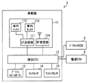
[車載機3の構成]
図2に示すように、車載機3は、通信部11、照合ECU12、アンロックセンサ13、ロックセンサ14、プッシュスタートボタン15を備える。
[Configuration of in-vehicle device 3]
As shown in FIG. 2, the vehicle-mounted
通信部11は、LF送信部111、車外アンテナ112、車内アンテナ113、RF受信部114を備える。LF送信部111は、リクエスト信号などの信号を、LF帯(たとえば135kHz)の搬送波で変調して車外アンテナ112、あるいは、車内アンテナ113から送信させる。車外アンテナ112、車内アンテナ113のいずれから信号を送信させるかは、送信する信号のトリガが何であるかにより定まる。たとえば、アンロックセンサ13あるいはロックセンサ14がユーザ操作を検出した場合には車外アンテナ112が用いられ、プッシュスタートボタン15が操作された場合には、車内アンテナ113が用いられる。
The
アンロックセンサ13は、車両4のドアハンドルあるいはその付近に設置され、車両4のドアのロックを解錠させる際にユーザが触れるセンサである。ロックセンサ14は、車両4のドアハンドルあるいはその付近に設置され、車両4のドアをロックさせる際にユーザが触れるセンサである。プッシュスタートボタン15は、車両4の駆動源を駆動状態あるいは駆動許可状態にする際にユーザが操作するボタンであり、車両4の車室に配置される。車両4の駆動源は、たとえば、エンジンおよびモータの一方または両方である。
The
車外アンテナ112は、車両4のドアハンドル内などに設けられ、車両4の外部へ電波を送信する。車内アンテナ113は、車室内などに設けられ、車両4の内部に電波を送信する。
The vehicle
車外アンテナ112から車両4の外部へリクエスト信号が送信された場合、リクエスト信号を受信できる範囲は、車両4の周囲の1m程度である。電子キー2は、リクエスト信号を受信すると、RF帯(たとえば315MHz)の電波でレスポンス信号を返信する。RF受信部114は、電子キー2が送信した信号を受信して復調する。
When the request signal is transmitted from the vehicle
照合ECU12は、CPU、ROM、RAM等を備えたコンピュータであり、CPUが、RAMの一時記憶機能を利用しつつ、ROMなどの非遷移的実体的な記録媒体に記憶されているプログラムを実行する。これにより、照合ECU12は、種々の制御を実行する。なお、CPUが、上記プログラムを実行することは、プログラムに対応する方法が実行されることを意味する。また、照合ECU12が実行する機能の一部または全部を、一つあるいは複数のIC等によりハードウェア的に構成してもよい。
The
たとえば、照合ECU12は、電子キー2に送信する信号を生成する。この信号は、たとえば、電子キー2に応答を要求するリクエスト信号である。そして、照合ECU12は、生成した信号をLF送信部111に出力する。
For example, the
また、照合ECU12は、RF受信部114が復調した信号を解析する。具体的には、復調した信号が、電子キー2が送信した信号であって、かつ、その信号にIDコードが含まれており、そのIDコードが、正規のIDコードと一致するか否か(つまり、照合成立か否か)を判定する。
Further, the
リクエスト信号を車内アンテナ113から送信させ、そのリクエスト信号に応答して電子キー2から送信された信号を用いた照合を車室内照合という。一方、リクエスト信号を車外アンテナ112から送信させ、そのリクエスト信号に応答して電子キー2から送信された信号を用いた照合を車外照合と言う。なお、車外照合は、車室外照合と言われることもある。
The verification using the signal transmitted from the
車載機3は、車外照合条件が成立している状態では周期的に車外照合を行い、車室内照合条件が成立した場合には車室内照合を行う。車外照合条件は、たとえば、電源オフかつドアロック状態である。アンロックセンサ13がオンになったこと、ロックセンサ14がオンなったことも車外照合条件の一例である。
The vehicle-mounted
車室内照合条件の一例として、ドライバが車室内にいるときに可能な所定の操作が行われたとき、という条件がある。この所定の操作は、たとえば、ブレーキペダルの踏み込み操作である。また、プッシュスタートボタン15の操作も、所定の操作の一例である。
An example of the vehicle interior matching condition is a condition that a predetermined operation that can be performed while the driver is in the vehicle interior is performed. This predetermined operation is, for example, a depression operation of the brake pedal. The operation of the
照合ECU12は、ドアロックECU5、電源ECU6と接続されている。ドアロックECU5は、車両4のドアのロック機構がロック状態になっているかアンロック状態になっているかを検出する。また、そのロック機構が備えるロックモータおよびアンロックモータを駆動して、ロック機構をロック状態からアンロック状態へ、または、アンロック状態からロック状態に切り替える。電源ECU6は、エンジンなどの駆動源を制御するECUに対して、始動要求信号を送信する。
The
ロックセンサ14がオンなったことに基づいて実行した車外照合が成立した場合、照合ECU12は、ドアロックECU5へ、車両4のドアのロック機構をロック状態とすることを指示する信号を出力する。プッシュスタートボタン15が押されたことに基づいて実行した車室内照合が成立した場合、照合ECU12は、電源ECU6へ、駆動源の始動を指示する信号を出力する。
When the vehicle exterior verification executed based on the
[電子キー2の構成]
図3に示すように、電子キー2は、LF受信部21、RF送信部22、施錠スイッチ23、解錠スイッチ24、加速度センサ25、キー制御部26を備えている。なお、この他に、ドア開閉スイッチ、メカニカルキーなどを備えていてもよい。
[Configuration of electronic key 2]
As shown in FIG. 3, the
LF受信部21は、車載機3から送信されたリクエスト信号を復調するための構成であり、LF帯の電波を受信し、その電波を復調して、リクエスト信号を取り出す。このLF受信部21が請求項の受信部に相当する。
The
RF送信部22は、キー制御部26が生成したリクエスト信号などの信号をRF帯の搬送波(たとえば315MHz)で変調して送信する。このRF送信部22が請求項の送信部に相当する。
The
施錠スイッチ23および解錠スイッチ24は、電子キー2の表面に配置され、ユーザが押すことができる。施錠スイッチ23は、車両4のドアロックを解錠することを指示する際にユーザが押すスイッチである。解錠スイッチ24は、車両4のドアロックを施錠することを指示する際にユーザが押すスイッチである。
The
加速度センサ25は、検出素子部251、センサ信号処理部252、メモリ253を備える。検出素子部251は、この加速度センサ25が内蔵されている電子キー2に生じる加速度を検出する素子である。この素子は、たとえば、センサ素子可動部と固定部とを備えて、それらの間の静電容量変化を検出する静電容量検出方式の素子である。他にも、ピエゾ抵抗方式など、他の方式で加速度を検出する素子を用いてもよい。検出素子部251は、3軸方向の加速度をそれぞれ検出できることが好ましいが、2軸あるいは1軸の方向のみ加速度が検出可能でもよい。
The
センサ信号処理部252は、検出素子部251からの信号を増幅、調整し、検出素子部251が検出した加速度を電気信号として出力する。センサ信号処理部252は、たとえば、ASICにより構成される。メモリ253は、振動検出フラグを格納するフラグ格納領域を備えており、フラグ記憶部として機能する。センサ信号処理部252は、演算機能を備えており、通知モードおよびフラグモードを選択的に切り換えて作動する。
The sensor
通知モードでは、センサ信号処理部252は、予め設定した閾値と、検出素子部251が検出した加速度を比較して、閾値以上の振動を検出したと判断した場合に、そのことを示す振動検出信号をキー制御部26に出力する。閾値は、電子キー2を携帯したユーザが歩いたときに電子キー2に生じる振動を検出する目的で大きさを決める。よって、電子キー2を携帯したユーザが歩いたときに電子キー2に生じる振動よりも、少し小さい値に閾値の大きさを設定する。
In the notification mode, when the sensor
一方、フラグモードでは、センサ信号処理部252は、上記閾値と検出素子部251が検出した加速度を比較して、閾値以上の振動を検出したと判断した場合には、振動検出フラグをセットする。
On the other hand, in the flag mode, the sensor
キー制御部26は、CPU、ROM、RAM等を備えたコンピュータであり、CPUが、RAMの一時記憶機能を利用しつつ、ROMなどの非遷移的実体的な記録媒体に記憶されているプログラムを実行する。これにより、キー制御部26は種々の制御を行う。CPUが上記プログラムを実行することは、プログラムに対応する方法が実行されることを意味する。また、キー制御部26が実行する機能の一部または全部を、一つあるいは複数のIC等によりハードウェア的に構成してもよい。
The
キー制御部26は、たとえば、受信データの解析を行う。詳しくは、LF受信部21が復調した信号を解析して、その信号がリクエスト信号であるか否かを判定する。また、キー制御部26は、送信信号を生成し、生成した信号をRF送信部22に出力する。生成する信号は、たとえば、リクエスト信号に応答して送信するレスポンス信号である。レスポンス信号には、予め記憶されているIDコードを含ませる。
The
車載機3は、周期的にリクエスト信号を送信する状態がある。このリクエスト信号に応答するためには受信待機状態にする必要がある。受信待機状態は、リクエスト信号を受信して、そのリクエスト信号に応答するレスポンス信号を送信可能な状態である。つまり、受信待機状態は、リクエスト信号に対する応答が許可されている応答許可状態である。
The vehicle-mounted
受信待機状態では、LF受信部21に通電しているため暗電流が流れる。消費電力を低減するために、電子キー2は、スリープ状態も可能になっている。スリープ状態では、LF受信部21に通電されないので、消費電力は低くなる。また、スリープ状態では、リクエスト信号に応答しないので、リクエスト信号に対する応答が許可されていない応答不許可状態である。
In the reception standby state, a dark current flows because the
電子キー2が携帯されていない状態では、電子キー2が車両4に近づくことはないと考えてよい。また、電子キー2が携帯されて車両4に近づく際には、電子キー2に振動が生じる。そこで、キー制御部26は、加速度センサ25からの信号に基づいて、振動を検出したか否かを判断する。そして、振動を検出したと判断したら受信待機状態とする。
It may be considered that the
ただし、加速度センサ25とキー制御部26との間で信号を送受信するためにも電力を消費する。よって、加速度センサ25とキー制御部26との間で頻繁に信号を送信することは、消費電力低減の観点から好ましくない。そこで、本実施形態では、加速度センサ25は閾値以上の振動を検出したら振動検出フラグをメモリ253にセットし、キー制御部26は一定周期で振動検出フラグがセットされているか否かを読み出す。
However, power is also consumed to transmit and receive signals between the
[振動検出フラグの処理]
図4は振動検出フラグのセットおよびリセットに関するセンサ信号処理部252の処理を示すフローチャートである。センサ信号処理部252は、通電状態において、図4に示す処理を周期的に実行する。
[Processing of vibration detection flag]
FIG. 4 is a flowchart showing the processing of the sensor
ステップ(以下、ステップを省略)S1では、検出素子部251が出力する信号に基づいて、閾値以上の振動を検出したか否かを判断する。この判断がNOであればS3に進む。
In step (hereinafter, step is omitted) S1, it is determined based on a signal output from the
一方、S1の判断がYES、すなわち、閾値以上の振動を検出したと判断した場合にはS2へ進む。S2では、振動検出フラグをセットする。振動検出フラグをセットするとは、ここでは、メモリ253のフラグ格納領域に格納されている振動検出フラグの値を1にすることである。
On the other hand, if the determination in S1 is YES, that is, if it is determined that the vibration above the threshold value is detected, the process proceeds to S2. In S2, the vibration detection flag is set. Setting the vibration detection flag here means setting the value of the vibration detection flag stored in the flag storage area of the
S2を実行した場合、または、S1の判断がNOであった場合にはS3に進む。S3では、前回のS3の実行以降において、キー制御部26により振動検出フラグが読み出されたか否かを判断する。キー制御部26が振動検出フラグを読み出すためには、キー制御部26は、センサ信号処理部252と通信を行って振動検出フラグの値を出力することを指示する。よって、センサ信号処理部252は振動検出フラグが読み出されたかどうかを判断することができる。
When S2 is executed, or when the determination in S1 is NO, the process proceeds to S3. In S3, it is determined whether or not the vibration detection flag has been read by the
振動検出フラグが読み出されたと判断した、すなわち、S3の判断がYESになった場合にはS4に進む。S4では、振動検出フラグをリセットすなわち0にして、図4の処理を終了する。一方、S3の判断がNOであればS4を実行することなく、図4の処理を終了する。図4の処理を終了した場合、図4の処理の実行周期が経過した後に、再度、図4の処理を実行する。この実行周期は、たとえば、加速度センサ25の振動検出周期と同じとする。
When it is determined that the vibration detection flag has been read, that is, when the determination in S3 is YES, the process proceeds to S4. In S4, the vibration detection flag is reset, that is, set to 0, and the process of FIG. 4 is terminated. On the other hand, if the determination in S3 is NO, the process in FIG. 4 ends without executing S4. When the processing of FIG. 4 is completed, the processing of FIG. 4 is executed again after the execution cycle of the processing of FIG. 4 has elapsed. This execution cycle is, for example, the same as the vibration detection cycle of the
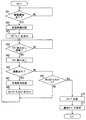
[受信待機状態とスリープ状態の切り換え]
図5はキー制御部26が実行する処理のうち、受信待機状態とスリープ状態の切り換えに関する処理を示すフローチャートである。キー制御部26は、通電状態において、図5に示す処理を周期的に実行する。
[Switching between reception standby state and sleep state]
FIG. 5 is a flowchart showing a process related to switching between the reception standby state and the sleep state among the processes executed by the
S11では、前回、フラグを読み出してからの経過時間がフラグ読み出し周期を超えたか否かを判断する。フラグ読み出し周期は、センサ信号処理部252が図4の処理を実行する実行周期よりも長い周期に設定される。なお、S11でこの判断を行うことから、図5の実行周期は、フラグ読み出し周期よりは短い周期に設定される。
In S11, it is determined whether or not the time elapsed since the flag was last read exceeds the flag read cycle. The flag read cycle is set to a cycle longer than the execution cycle in which the sensor
S11の判断がNOであれば、図5の処理を終了する。S11の判断がYESであればS12へ進む。なお、電源オン後、初回の図5の実行時も、S11の判断をYESとする。S12では、加速度センサ25のセンサ信号処理部252と通信を行って振動検出フラグを読み出す。S13では、S12で読み出した振動検出フラグに基づいて、振動が生じていたか否かを判断する。具体的には、振動検出フラグが1であれば振動が生じていたと判断し、振動検出フラグが0であれば振動は生じていなかったと判断する。
If the determination in S11 is NO, the process of FIG. 5 ends. If the determination in S11 is YES, the process proceeds to S12. It should be noted that the determination in S11 is also YES when executing FIG. 5 for the first time after the power is turned on. In S12, the vibration detection flag is read by communicating with the sensor
S13の判断がYESであればS14に進む。S14では受信待機状態とする。S14を実行する時点においてスリープ状態であれば受信待機状態に切り換え、S14を実行する時点において受信待機状態になっていれば、受信待機状態を継続することになる。 If the determination in S13 is YES, the process proceeds to S14. In S14, the reception standby state is set. If it is in the sleep state at the time of executing S14, it is switched to the reception standby state, and if it is in the reception standby state at the time of executing S14, the reception standby state is continued.
S13の判断がNOであればS15に進む。S15ではスリープ状態とする。S15を実行する時点において受信待機状態であればスリープ状態に切り換え、S14を実行する時点においてスリープ状態になっていれば、スリープ状態を継続することになる。S14またはS15を実行したら図5の処理を終了する。 If the determination in S13 is no, the process proceeds to S15. In S15, the sleep state is set. If it is in the reception standby state at the time of executing S15, it is switched to the sleep state, and if it is in the sleep state at the time of executing S14, the sleep state is continued. After executing S14 or S15, the process of FIG. 5 is ended.
[第1実施形態のまとめ]
この第1実施形態では、加速度センサ25は、閾値以上の振動を検出したことに基づいて、振動検出フラグをセットする。そして、キー制御部26が、周期的に振動検出フラグを読み出し、振動検出フラグがセットされていれば、受信待機状態、すなわち応答許可状態とする。よって、加速度センサ25は、加速度を検出する毎に、検出した加速度をキー制御部26に通知する必要がない。そのため、加速度センサ25とキー制御部26との間の通信頻度を低減することが可能になるので、消費電力を低減することができる。
[Summary of First Embodiment]
In the first embodiment, the
<第2実施形態>
次に、第2実施形態を説明する。この第2実施形態以下の説明において、それまでに使用した符号と同一番号の符号を有する要素は、特に言及する場合を除き、それ以前の実施形態における同一符号の要素と同一である。また、構成の一部のみを説明している場合、構成の他の部分については先に説明した実施形態を適用できる。
<Second Embodiment>
Next, a second embodiment will be described. In the following description of the second embodiment, elements having the same reference numerals as those used up to that point are the same as the elements having the same reference numerals in the previous embodiments, unless otherwise specified. Further, when only a part of the configuration is described, the above-described embodiment can be applied to the other part of the configuration.
第2実施形態では、加速度センサ25のセンサ信号処理部252は、フラグモードと通知モードを切り換えて実行可能である。フラグモードは、閾値以上の振動を検出した場合に振動検出フラグをメモリ253にセットするモードである。一方、通知モードは、閾値以上の振動を検出した場合、キー制御部26からの要求を待つことなく、閾値以上の振動を検出したこと示す振動検出信号をキー制御部26に出力するモードである。
In the second embodiment, the sensor
図6は、図5に代えて電子キー2のキー制御部26が実行する処理を示すフローチャートであり、図7は、図4に代えて加速度センサ25のセンサ信号処理部252が実行する処理を示すフローチャートである。第2実施形態は、これら図6、7に示す処理を実行する点において第1実施形態と相違する。
6 is a flowchart showing a process executed by the
まず、図6を用いて、第2実施形態における、キー制御部26が実行する受信状態とスリープ状態の切り換え処理を説明する。キー制御部26は、通電状態において、図6に示す処理を繰り返し実行する。なお、通電開始時点では、電子キー2はスリープ状態である。
First, the switching process between the reception state and the sleep state executed by the
通電開始時点では、電子キー2はスリープ状態である。また、その後、S31を実行することになる場合、S38が実行されている。したがって、S31はスリープ状態で実行する。
At the time of starting energization, the
S31では、加速度センサ25から振動通知があったか否かを判断する。この判断は、振動検出信号を取得したか否かにより行う。S31の判断がNOであればS31を繰り返す。一方、S31の判断がYESであればS32へ進む。
In S31, it is determined whether or not there is a vibration notification from the
S32では、受信待機状態に切り替える。S33では、センサ信号処理部252にフラグモードを指示する。S34〜S38は図5のS11〜S15と同じである。したがって、S34においてフラグ読み出し周期となったと判断した場合に、S35を実行して振動検出フラグを読み出す。S36では、振動検出フラグの値から、振動が生じていたか否かを判断する。振動が生じていたと判断した場合には、S37にて受信待機状態とする。S37を実行したらS34に戻る。したがって、振動が生じていたと判断した場合には、受信待機状態を継続することになる。
In S32, it switches to the reception standby state. In S33, the sensor
S36において振動が生じてしないと判断した場合にはS38に進み、スリープ状態に移行する。また、S39を実行して、センサ信号処理部252に通知モードを指示する。これにより、加速度センサ25が閾値以上の振動を検出した場合には、加速度センサ25からそのことが通知される。そこで、キー制御部26はS31に戻る。
If it is determined in S36 that vibration does not occur, the process proceeds to S38 and shifts to the sleep state. In addition, S39 is executed to instruct the sensor
次に、センサ信号処理部252が実行する処理を説明する。センサ信号処理部252は、通電状態において、図7に示す処理を周期的に実行する。図7の実行周期は図4と同じである。S41では、フラグモードであるか否かを判断する。フラグモードであればS46に進む。
Next, the processing executed by the sensor
一方、フラグモードでない、すなわち、通知モードである場合にはS42へ進む。S42では、キー制御部26からフラグモードへの切り換えが指示されたか否かを判断する。S42の判断がNOであればS43に進む。S43では、閾値以上の振動を検出したか否かを判断する。S43の処理は、図4のS1と同じである。S43の判断がYESであればS44に進む。
On the other hand, when the flag mode is not set, that is, when the notification mode is set, the process proceeds to S42. In S42, it is determined whether the
S44では、振動を検知したことをキー制御部26に通知するために、振動検出信号をキー制御部26に出力する。S44を実行したらS42に戻る。S43の判断がNOであれば、S44を実行することなくS42に戻る。S42の判断がYESであればS45に進む。S45では、フラグモードに切り替える。その後、S46に進む。
In S44, a vibration detection signal is output to the
S46〜S49は、図4のS1〜S4と同じである。したがって、S46において、閾値以上の振動を検出したと判断したら、S47で振動検出フラグをセットする。また、S48で、振動検出フラグが読み出されたと判断したら、S49で振動検出フラグをリセットする。S49を実行した場合、またはS48の判断がNOであった場合にはS50に進む。 S46 to S49 are the same as S1 to S4 in FIG. Therefore, when it is determined in S46 that the vibration equal to or greater than the threshold value is detected, the vibration detection flag is set in S47. If it is determined in S48 that the vibration detection flag has been read, the vibration detection flag is reset in S49. When S49 is executed or when the determination in S48 is NO, the process proceeds to S50.
S50では、キー制御部26から通知モードへの切り換えが指示されたか否かを判断する。S50の判断がYESであればS51に進む。S51では、通知モードに切り替える。その後、図7の処理を終了する。一方、S50の判断がNOであればS51を実行することなく図7の処理を終了する。
In S50, it is determined whether the
次に、
この第2実施形態では、加速度センサ25は、通知モードになっているときは、閾値以上の振動を検出したら振動検出信号をキー制御部26に出力する。キー制御部26は、この振動検出信号を取得したら受信待機状態とする(S32)。
next,
In the second embodiment, when in the notification mode, the
スリープ状態では、車載機3が送信するリクエスト信号に応答することができない。そのため、リクエスト信号を受信できる位置に電子キー2が存在しており、リクエスト信号に応答すべき状態であるのにスリープ状態になっていると、リクエスト信号に対する応答性が低下する。この応答性の低下を抑制するために、振動を検出したら電子キー2は受信待機状態に移行する。
In the sleep state, it cannot respond to the request signal transmitted by the vehicle-mounted
振動検出信号は、受信待機状態とするための信号であることから、すでに受信待機状態となっていれば、キー制御部26は、振動検出信号を迅速に取得する必要性は低い。そこで、キー制御部26は、受信待機状態とした場合には、S33を実行して加速度センサ25をフラグモードとする。
Since the vibration detection signal is a signal for setting the reception standby state, it is not necessary for the
つまり、この第2実施形態では、閾値以上の振動が生じたことを迅速に把握する必要性が低い状況で、キー制御部26は加速度センサ25をフラグモードとするので、リクエスト信号に対する応答性の低下を抑制しつつ、消費電力を低減できる。一方、スリープ状態では、キー制御部26は加速度センサ25を通知モードとする。これにより、電子キー2がユーザにより持ち上げられると、電子キー2はすぐに受信待機状態となる。その後、電子キー2がユーザにより携帯されて移動している間も電子キー2は受信待機状態が継続するので、迅速に、リクエスト信号に応答することもできる。
That is, in the second embodiment, the
<第3実施形態>
第3実施形態では、図6に示す処理に代えて、図8に示す処理を実行する。図8においてS61〜S67は、図6のS31〜S37と同じ処理を実行する。S67を実行した後はS68を実行する。S68では、カウントダウンタイマーをリセットする。このカウントダウンタイマーは、振動が検出されていない時間が一定時間継続したと判断するために用いている。したがって、S66で振動ありと判断した場合には、カウントダウンタイマーを初期値にリセットするのである。カウントダウンタイマーの初期値は、フラグ読み出し周期よりは長い時間に設定され、たとえば、数分である。カウントダウンタイマーの初期値は、請求項の最低継続時間に相当する。
<Third Embodiment>
In the third embodiment, the process shown in FIG. 8 is executed instead of the process shown in FIG. 8, steps S61 to S67 execute the same processes as steps S31 to S37 of FIG. After executing S67, S68 is executed. In S68, the countdown timer is reset. This countdown timer is used to determine that the time during which no vibration is detected has continued for a certain period of time. Therefore, when it is determined that there is vibration in S66, the countdown timer is reset to the initial value. The initial value of the countdown timer is set to a time longer than the flag read cycle, and is, for example, several minutes. The initial value of the countdown timer corresponds to the minimum duration of the claims.
S66の判断がNOになった場合、すなわち、振動が検出されていなかったと判断した場合にはS69へ進む。S69では、カウントダウンタイマーが0になったか否かを判断する。この判断は、加速度センサ25が継続して閾値以上の振動を検出していない時間が、最低継続時間を超えたか否かを判断するものである。
When the determination in S66 is NO, that is, when it is determined that the vibration is not detected, the process proceeds to S69. In S69, it is determined whether or not the countdown timer has reached 0. This determination is to determine whether the time during which the
S69の判断がYESになれば、S70、S71を実行する。S70、S71は、それぞれ、図6のS38、S39と同じであり、S70ではスリープ状態に移行し、S71では、センサ信号処理部252に通知モードを指示する。
If the determination in S69 is YES, S70 and S71 are executed. S70 and S71 are the same as S38 and S39 of FIG. 6, respectively. In S70, the sleep state is entered, and in S71, the sensor
S69の判断がNOであれば、S70、S71を実行することなく、S64に戻る。よって、カウントダウンタイマーが0になっていなければ、S66において振動なしと判断していても、スリープ状態には移行しないことになる。 If the determination in S69 is NO, the process returns to S64 without executing S70 and S71. Therefore, if the countdown timer is not 0, the state does not shift to the sleep state even if it is determined in S66 that there is no vibration.
この第3実施形態では、キー制御部26は、振動検出フラグを読み出して、振動が検出されていなかったと判断しても、すぐには加速度センサ25に通知モードへの切り換えを指示しない。キー制御部26は、振動が検出されていない時間が、カウントダウンタイマーの初期値として定められた時間継続した場合に、加速度センサ25に通知モードへの切り換えを指示する。
In the third embodiment, the
これにより、通知モードへの切り換えを指示する頻度も低減する。通知モードへの切り換えを指示する際にも、電力を消費するので、通知モードへの切り換えを指示する頻度が低減することで、消費電力をより低減できる。 This also reduces the frequency of instructing switching to the notification mode. Since power is consumed also when instructing to switch to the notification mode, it is possible to further reduce power consumption by reducing the frequency of instructing to switch to the notification mode.
通知モードでは、閾値以上の振動が生じなければ、加速度センサ25とキー制御部26との間の通信が行われない。したがって、振動が生じない可能性が高い状況では、通知モードとしたほうが、消費電力を低減できる。しかし、フラグ読み出し周期の間、振動が生じていなかったという程度では、一時的にユーザが立ち止まった状態などであり、再度、振動が生じる可能性も高い。
In the notification mode, the communication between the
そこで、この第3実施形態では、振動が検出されていない時間が、カウントダウンタイマーの初期値として定められた時間継続した場合に、加速度センサ25に通知モードへの切り換えを指示する。これにより、加速度センサ25とキー制御部26との間の通信回数が少なくなり、消費電力をより低減できる。
Therefore, in the third embodiment, if the vibration is not detected for a period of time set as the initial value of the countdown timer, the
<第4実施形態>
第4実施形態は、第3実施形態の改良であり、電子キー2が車両4の車室内にあると判断したときと、電子キー2が車外に持ち出された可能性が生じたと判断したときに、カウントダウンタイマーの初期値を変更する。カウントダウンタイマーの初期値を変更するために、第4実施形態では、キー制御部26は、第3実施形態で示した処理に加えて、図9、図10に示す処理を実行する。
<Fourth Embodiment>
The fourth embodiment is an improvement of the third embodiment, and when it is determined that the
図9は、電子キー2が車両4の外にあると判断している状態で周期的に実行する。S81では、電子キー2が車両4の車室内に持ち込まれたか否かを判断する。この判断自体は、直接的には車載機3が行い、その判断結果を、通信により車載機3から取得する。
FIG. 9 is periodically executed in a state where it is determined that the
電子キー2が車両4の車室内に持ち込まれたか否かを車載機3が判断する手法は、種々知られている。たとえば、車外照合が成立した後、車両4のドアが開いた後、そのドアが閉となり、次いで、車室内照合が成立した場合に、電子キー2が車両4の車室内に持ち込まれた判断する。
Various methods are known for the vehicle-mounted
S81の判断がNOであればS82を実行することなく、図9の処理を終了する。一方、S81の判断がYESになればS82へ進む。S82では、カウントダウンタイマーの初期値を、電子キー2が車室内に持ち込まれているとき用の値、以下、車室内用初期値にする。車室内用初期値に対して、電子キー2が車外にあるときに用いる初期値を、車外用初期値とする。
If the determination in S81 is NO, the process of FIG. 9 ends without executing S82. On the other hand, if the determination in S81 is YES, the process proceeds to S82. In S82, the initial value of the countdown timer is set to a value for when the
車室内用初期値は、車外用初期値よりも長い。具体的には、たとえば、車外用初期値が数分であるのに対して、車室内用初期値は数時間である。数時間は例であり、具体的時間は適宜変更できる。 The vehicle interior initial value is longer than the vehicle exterior initial value. Specifically, for example, the initial value for the vehicle exterior is several minutes, whereas the initial value for the vehicle interior is several hours. Several hours is an example, and the specific time can be changed as appropriate.
車外用初期値を長くする理由は、車室内照合を成立させるためである。前述したように、車載機3は、車室内照合条件が成立している状態では車室内照合を行う。車室内照合を行うとき、電子キー2が車室内に存在していれば、車室内照合が成立する必要がある。車室内照合が成立するためには、電子キー2は受信待機状態である必要がある。
The reason for increasing the initial value for outside the vehicle is to establish the vehicle interior verification. As described above, the vehicle-mounted
第3実施形態で説明したカウントダウンタイマーを用いる場合、受信待機状態である時間は、閾値以上の振動を加速度センサ25が最後に検出してから、カウントダウンタイマーが0になるまでの間である。電子キー2が車室内に持ち込まれている状態で、加速度センサ25が値以上の振動を検出する頻度は、車両4が凹凸のある路面を走行したときなど、電子キー2をユーザが携帯している状況と比較して少ない。そこで、電子キー2が車両4の車室内に持ち込まれたと判断した場合には、カウントダウンタイマーの初期値を、車外用初期値よりも長い車室内用初期値とするのである。
When the countdown timer described in the third embodiment is used, the time in the reception standby state is from the time when the
電子キー2が車室内に持ち込まれたと判断している状況では、図9に代えて図10を実行する。S91では、電子キー2が車両4の外に持ち出されたか否かを判断する。この判断も、直接的には車載機3が行い、その判断結果を、通信により車載機3から取得する。
When it is determined that the
電子キー2が車両4の外に持ち出されたか否かを車載機3が判断する手法も、種々知られている。たとえば、電子キー2が車室内にあると判断している状況で車両4のドアが開いた場合に、電子キー2が車両4の外に持ち出されたと判断する。
Various methods are known for the in-
なお、電子キー2が車室内にあると判断している状況で車両4のドアが開いただけでは、電子キー2が車外へ持ち出される可能性が生じただけである。車載機3は、電子キー2が車外へ持ち出される可能性が生じた場合、車外照合を行う。この車外照合が成立したこと、あるいは、開いていたドアが閉じた後、車外照合が成立したことを、電子キー2が車外に持ち出されたと判断する条件としてもよい。
It should be noted that if the door of the vehicle 4 is only opened while it is determined that the
S91の判断がNOであればS92を実行することなく、図10の処理を終了する。一方、S91の判断がYESになればS92へ進む。S92では、カウントダウンタイマーの初期値を、車外用初期値にする。 If the determination in S91 is NO, the process of FIG. 10 ends without executing S92. On the other hand, if the determination in S91 is YES, the process proceeds to S92. In S92, the initial value of the countdown timer is set to the external vehicle initial value.
この第4実施形態では、第3実施形態と同様に、加速度センサ25とキー制御部26との間の通信回数を低減させることができる。加えて、車室内照合が成立しなくなってしまう恐れも軽減できる。
In the fourth embodiment, the number of communications between the
以上、本発明の実施形態を説明したが、本発明は上述の実施形態に限定されるものではなく、次の変形例も本発明の技術的範囲に含まれ、さらに、下記以外にも要旨を逸脱しない範囲内で種々変更して実施できる。 Although the embodiments of the present invention have been described above, the present invention is not limited to the above-described embodiments, and the following modified examples are also included in the technical scope of the present invention. Various modifications can be made without departing from the scope.
<変形例1>
前述した実施形態において、通知モードでは、加速度センサ25は閾値以上の振動を検出した場合に振動検出信号をキー制御部26に出力していた。しかし、通知モードにおいて、加速度センサ25は、検出した加速度の大きさによらず、検出した加速度の大きさを示す信号を、逐次、キー制御部26に出力してもよい。
<
In the above-described embodiment, in the notification mode, the
1:車両電子キーシステム 2:電子キー 3:車載機 4:車両 5:ドアロックECU 6:電源ECU 11:通信部 12:照合ECU 13:アンロックセンサ 14:ロックセンサ 15:プッシュスタートボタン 21:LF受信部 22:RF送信部 23:施錠スイッチ 24:解錠スイッチ 25:加速度センサ 26:キー制御部 111:LF送信部 112:車外アンテナ 113:車内アンテナ 114:RF受信部 251:検出素子部 252:センサ信号処理部 253:メモリ 1: Vehicle electronic key system 2: Electronic key 3: Vehicle-mounted device 4: Vehicle 5: Door lock ECU 6: Power supply ECU 11: Communication unit 12: Verification ECU 13: Unlock sensor 14: Lock sensor 15: Push start button 21: LF receiving unit 22: RF transmitting unit 23: Locking switch 24: Unlocking switch 25: Acceleration sensor 26: Key control unit 111: LF transmitting unit 112: Exterior antenna 113: In-vehicle antenna 114: RF receiving unit 251: Detection element unit 252 : Sensor signal processing unit 253: Memory
Claims (4)
前記リクエスト信号に応答するレスポンス信号を送信する送信部(22)と、
前記受信部からの信号に基づいて前記リクエスト信号を受信したか否かを判断し、前記リクエスト信号を受信したと判断したことに基づいて、前記送信部から前記レスポンス信号を送信させるキー制御部(26)とを備えた車両用電子キーであって、
前記車両用電子キーに生じる加速度を検出し、検出した加速度から、閾値以上の振動を検出したと判断したことに基づいて、振動検出フラグをセットする加速度センサ(25)を備え、
前記キー制御部は、前記振動検出フラグを、前記加速度センサが前記振動検出フラグをセットする周期よりも長い周期に設定されたフラグ読み出し周期ごとに読み出し、前記振動検出フラグがセットされていることに基づいて前記リクエスト信号に応答する応答許可状態とする車両用電子キー。
A receiver (21) for receiving a request signal transmitted by an in-vehicle device mounted on the vehicle,
A transmitter (22) for transmitting a response signal in response to the request signal,
It is determined whether or not the request signal is received based on a signal from the receiving unit, and based on the determination that the request signal is received, a key control unit that causes the transmitting unit to transmit the response signal ( 26) An electronic key for a vehicle comprising:
An acceleration sensor (25) for setting a vibration detection flag on the basis of detecting acceleration generated in the vehicle electronic key and judging from the detected acceleration that vibration of a threshold value or more is detected,
The key control unit reads the vibration detection flag at every flag reading cycle set to a cycle longer than the cycle at which the acceleration sensor sets the vibration detection flag, and the vibration detection flag is set. An electronic key for a vehicle, which is set to a response-permitted state based on the request signal.
前記加速度センサは、前記閾値以上の振動を検出した場合に前記振動検出フラグをセットするフラグモードと、前記閾値以上の振動を検出した場合に、そのことを示す振動検出信号を前記キー制御部に出力する通知モードとを切り替えて実行可能であり、
前記キー制御部は、前記振動検出信号を取得したことに基づいて、前記応答許可状態とし、かつ、前記フラグモードとすることを前記加速度センサに指示する車両用電子キー。 In claim 1,
When the acceleration sensor detects a vibration equal to or more than the threshold, a flag mode that sets the vibration detection flag, and when a vibration equal to or greater than the threshold is detected, a vibration detection signal indicating that to the key control unit. It is possible to switch between notification mode to output and execute,
An electronic key for a vehicle, wherein the key control unit instructs the acceleration sensor to set the response permission state and set the flag mode based on the acquisition of the vibration detection signal.
前記キー制御部は、前記振動検出フラグがセットされておらず、かつ、前記加速度センサが継続して前記閾値以上の振動を検出していない時間が最低継続時間を超えていることに基づいて、前記リクエスト信号に応答しない応答不許可状態とし、かつ、前記通知モードとすることを前記加速度センサに指示する車両用電子キー。 In claim 2,
The key control unit is based on that the vibration detection flag is not set, and that the acceleration sensor is continuously not detecting the vibration of the threshold value or more exceeds the minimum duration time, An electronic key for a vehicle, which instructs the acceleration sensor to set a response non-permission state that does not respond to the request signal and to set the notification mode.
前記キー制御部は、前記車両用電子キーが、前記車両の車室内に持ち込まれたと判断したことに基づいて、前記最低継続時間を、前記車両用電子キーが前記車両の外にある場合の前記最低継続時間よりも長くし、その後、前記車両用電子キーが、前記車両の外に持ち出されたと判断したことに基づいて、前記最低継続時間を、前記車両用電子キーが前記車両の外にある場合の前記最低継続時間とする車両用電子キー。 In claim 3,
The key control unit determines the minimum duration time based on the determination that the vehicle electronic key is brought into the vehicle interior of the vehicle, and the minimum duration is the time when the vehicle electronic key is outside the vehicle. The minimum duration is set to be longer than the minimum duration, and then the minimum duration is determined based on the determination that the vehicle electronic key is taken out of the vehicle, and the minimum duration is set to the vehicle electronic key is outside the vehicle. In the case of the electronic key for a vehicle, which has the minimum duration.
Priority Applications (4)
| Application Number | Priority Date | Filing Date | Title |
|---|---|---|---|
| JP2017050298A JP6686943B2 (en) | 2017-03-15 | 2017-03-15 | Electronic key for vehicle |
| PCT/JP2018/001888 WO2018168204A1 (en) | 2017-03-15 | 2018-01-23 | Vehicle electronic key |
| DE112018001338.3T DE112018001338T5 (en) | 2017-03-15 | 2018-01-23 | ELECTRONIC KEY FOR A VEHICLE |
| US16/509,672 US11299912B2 (en) | 2017-03-15 | 2019-07-12 | Vehicle electronic key |
Applications Claiming Priority (1)
| Application Number | Priority Date | Filing Date | Title |
|---|---|---|---|
| JP2017050298A JP6686943B2 (en) | 2017-03-15 | 2017-03-15 | Electronic key for vehicle |
Publications (3)
| Publication Number | Publication Date |
|---|---|
| JP2018154967A JP2018154967A (en) | 2018-10-04 |
| JP2018154967A5 JP2018154967A5 (en) | 2019-01-24 |
| JP6686943B2 true JP6686943B2 (en) | 2020-04-22 |
Family
ID=63523416
Family Applications (1)
| Application Number | Title | Priority Date | Filing Date |
|---|---|---|---|
| JP2017050298A Active JP6686943B2 (en) | 2017-03-15 | 2017-03-15 | Electronic key for vehicle |
Country Status (4)
| Country | Link |
|---|---|
| US (1) | US11299912B2 (en) |
| JP (1) | JP6686943B2 (en) |
| DE (1) | DE112018001338T5 (en) |
| WO (1) | WO2018168204A1 (en) |
Families Citing this family (3)
| Publication number | Priority date | Publication date | Assignee | Title |
|---|---|---|---|---|
| CN109801419A (en) * | 2019-01-23 | 2019-05-24 | 四川虹美智能科技有限公司 | A kind of method, apparatus that self-service machine is laid the key under the door and unmanned vending machine |
| IT202000019543A1 (en) * | 2020-08-06 | 2022-02-06 | Goffi Alberto Mario | ACCESS AND/OR ATTENDANCE CONTROL SYSTEM |
| CN112324252A (en) * | 2020-11-16 | 2021-02-05 | 珠海格力电器股份有限公司 | Intelligent door lock alarm method and device |
Family Cites Families (4)
| Publication number | Priority date | Publication date | Assignee | Title |
|---|---|---|---|---|
| JP2002021386A (en) * | 2000-07-11 | 2002-01-23 | Oki Electric Ind Co Ltd | Radio key system |
| JP2005330651A (en) * | 2004-05-18 | 2005-12-02 | Mitsubishi Motors Corp | Door unlocking controller |
| JP5830365B2 (en) | 2011-12-02 | 2015-12-09 | 株式会社東海理化電機製作所 | Electronic key and electronic key system |
| DE102017201087B4 (en) * | 2017-01-24 | 2019-08-14 | Volkswagen Aktiengesellschaft | Device, key remote and method for controlling operating conditions of a key module |
-
2017
- 2017-03-15 JP JP2017050298A patent/JP6686943B2/en active Active
-
2018
- 2018-01-23 DE DE112018001338.3T patent/DE112018001338T5/en active Pending
- 2018-01-23 WO PCT/JP2018/001888 patent/WO2018168204A1/en active Application Filing
-
2019
- 2019-07-12 US US16/509,672 patent/US11299912B2/en active Active
Also Published As
| Publication number | Publication date |
|---|---|
| WO2018168204A1 (en) | 2018-09-20 |
| JP2018154967A (en) | 2018-10-04 |
| US20190338562A1 (en) | 2019-11-07 |
| DE112018001338T5 (en) | 2019-11-21 |
| US11299912B2 (en) | 2022-04-12 |
Similar Documents
| Publication | Publication Date | Title |
|---|---|---|
| JP3988618B2 (en) | Vehicle remote control device | |
| JP6003938B2 (en) | Electronic key system | |
| US8860550B2 (en) | In-vehicle device controller | |
| JP5365979B2 (en) | Portable wireless communication device | |
| JP2008190244A (en) | Electronic key system, on-vehicle device for electronic key system and portable machine for electronic key system | |
| EP3412521B1 (en) | Control system, in-vehicle device and electronic key | |
| JP6686943B2 (en) | Electronic key for vehicle | |
| JP2007118899A (en) | Vehicular communication control system, on-vehicle device, and portable machine | |
| US10442398B2 (en) | Vehicle control system | |
| JP4690218B2 (en) | Portable device having wireless communication function | |
| US9889819B2 (en) | Smart key system | |
| CN113561938A (en) | Terminal, vehicle control system and vehicle control method | |
| JP4743221B2 (en) | Vehicle control device | |
| JP7031208B2 (en) | Vehicle collation system, vehicle electronic key system | |
| JP2017172193A (en) | Smart key system | |
| JP2011226222A (en) | Automatic control system for in-vehicle machine and vehicle equipped with the system | |
| JP2008202228A (en) | Electronic key system, and in-vehicle device for electronic key system | |
| JP2021185662A (en) | Remote vehicle control system and control terminal | |
| JP2018071213A (en) | Mobile device and control method thereof | |
| JP2002029385A (en) | Remote control device for vehicle | |
| WO2015098480A1 (en) | In-vehicle wireless communication device | |
| JP6629680B2 (en) | Vehicle control system, vehicle control device, portable device | |
| JP2015078523A (en) | Vehicle control system | |
| JP2005264461A (en) | Remote control device for car | |
| JP7376378B2 (en) | vehicle control system |
Legal Events
| Date | Code | Title | Description |
|---|---|---|---|
| A521 | Request for written amendment filed |
Free format text: JAPANESE INTERMEDIATE CODE: A523 Effective date: 20181203 |
|
| A621 | Written request for application examination |
Free format text: JAPANESE INTERMEDIATE CODE: A621 Effective date: 20181203 |
|
| A131 | Notification of reasons for refusal |
Free format text: JAPANESE INTERMEDIATE CODE: A131 Effective date: 20200107 |
|
| A521 | Request for written amendment filed |
Free format text: JAPANESE INTERMEDIATE CODE: A523 Effective date: 20200207 |
|
| TRDD | Decision of grant or rejection written | ||
| A01 | Written decision to grant a patent or to grant a registration (utility model) |
Free format text: JAPANESE INTERMEDIATE CODE: A01 Effective date: 20200303 |
|
| A61 | First payment of annual fees (during grant procedure) |
Free format text: JAPANESE INTERMEDIATE CODE: A61 Effective date: 20200316 |
|
| R151 | Written notification of patent or utility model registration |
Ref document number: 6686943 Country of ref document: JP Free format text: JAPANESE INTERMEDIATE CODE: R151 |
|
| R250 | Receipt of annual fees |
Free format text: JAPANESE INTERMEDIATE CODE: R250 |
|
| R250 | Receipt of annual fees |
Free format text: JAPANESE INTERMEDIATE CODE: R250 |